1
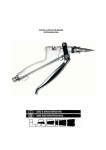
OI-UT003
TABLE OF CONTENTS
NOTES
– 16 –
1.0 Introduction . . . . . . . . . . . . . . . . . . . . . . . . . . . . . . . . . . . . . . . . . . . . . . . . . . .
2
2.0 Operation . . . . . . . . . . . . . . . . . . . . . . . . . . . . . . . . . . . . . . . . . . . . . . . . . . . . .
2.1 The Keypad
2.2 The Display
2.3 The Transducer
2.4 Making Measurements
2.5 Condition and Preparation of Surfaces
2.6 Selecting Measurement Mode
2.7 Calibration
3
3.0 TI-007 Modes . . . . . . . . . . . . . . . . . . . . . . . . . . . . . . . . . . . . . . . . . . . . . . . . . .
3.1 Scan Mode
3.2 Alarm Mode
3.3 Diff Mode
3.4 S-232 Port
8
4.0 Transducer Selection . . . . . . . . . . . . . . . . . . . . . . . . . . . . . . . . . . . . . . . . . . . .
10
5.0 Appendix A: Product Specification . . . . . . . . . . . . . . . . . . . . . . . . . . . . . . . . .
11
6.0 Appendix B: Application Notes . . . . . . . . . . . . . . . . . . . . . . . . . . . . . . . . . . . .
12
7.0 Appendix C: Sound Velocities of Common Materials . . . . . . . . . . . . . . . . .
13
8.0 Warranty Information . . . . . . . . . . . . . . . . . . . . . . . . . . . . . . . . . . . . . . . . . . .
14
–1–
1.0 INTRODUCTION
NOTES
The Electromatic Model TI-007 is a precision Ultrasonic Micrometer. Based on the
same operating principles as sonar, the TI-007 is capable of measuring the thickness
of various materials with accuracy as high as ± 0.0001 inches, or ± 0.001 millimeters.
The principle advantage of ultrasonic measurement over traditional methods is that
ultrasonic measurements can be performed with access to only one side of the material
being measured.
This manual is presented in three sections. The first section covers operation of the
TI-007, and explains the keypad controls and display. The second section provides
guidelines in selecting a transducer for a specific application. The last section provides
application notes and a table of sound velocity values for various materials.
Electromatic maintains a customer support resource in order to assist users with questions
or difficulties not covered in this manual. Customer support may be reached at any of the
following:
Electromatic Equipment Company
600 Oakland Avenue,
Cedarhurst, NY 11516 – USA
Telephone: (516)295-4300
Facsimile: (516) 295-4399
Online: www.checkline.com
Email: [email protected]
–2–
– 15 –
8.0 WARRANTY
2.0 OPERATION
ELECTROMATIC Equipment Co., Inc. (ELECTROMATIC) warrants to the original purchaser that this product is of merchantable quality and confirms in kind and quality with
the descriptions and specifications thereof. Product failure or malfunction arising out of
any defect in workmanship or material in the product existing at the time of delivery thereof which manifests itself within one year from the sale of such product, shall be remedied
by repair or replacement of such product, at ELECTROMATIC’s option, except where
unauthorized repair, disassembly, tampering, abuse or misapplications has taken place, as
determined by ELECTROMATIC. All returns for warranty or non-warranty repairs and/or
replacement must be authorized by ELECTROMATIC, in advance, with
all repacking and shipping expenses to the address below to be borne by the purchaser.
THE FOREGOING WARRANTY IS IN LIEU OF ALL OTHER WARRANTIES,
EXPRESSED OR IMPLIED, INCLUDING BUT NOT LIMITED TO, THE WARRANTY
OF MERCHANTABILITY AND FITNESS FOR ANY PARTICULAR PURPOSE OR
APPLICATION. ELECTROMATIC SHALL NOT BE RESPONSIBLE NOR LIABLE
FOR ANY CONSEQUENTIAL DAMAGE, OF ANY KIND OR NATURE, RESULTING
FROM THE USE OF SUPPLIED EQUIPMENT, WHETHER SUCH DAMAGE
OCCURS OR IS DISCOVERED BEFORE, UPON OR AFTER REPLACEMENT OR
REPAIR, AND WHETHER OR NOT SUCH DAMAGE IS CAUSED BY MANUFACTURER’S OR SUPPLIER’S NEGLIGENCE WITHIN ONE YEAR FROM INVOICE
DATE.
Some State jurisdictions or States do not allow the exclusion or limitation of incidental or
consequential damages, so the above limitation may not apply to you. The duration of any
implied warranty, including, without limitation, fitness for any particular purpose and
merchantability with respect to this product, is limited to the duration of the foregoing
warranty. Some states do not allow limitations on how long an implied warranty lasts
but, not withstanding, this warranty, in the absence of such limitations, shall extend for
one year from the date of invoice.
ELECTROMACTIC Equipment Co., Inc.
600 Oakland Ave. Cedarhurst, NY 11516—USA
Tel: 1-800-645-4330/ Tel: 516-295-4300/ Fax: 516-295-4399
The TI-007 interacts with the operator through the membrane
keypad and the LCD display. The functions of the various keys
on the keypad are detailed below, followed by an explanation of
the display and its various symbols.
ALRM
CAL
IN
MM
DIFF
SEND
SCAN
ON
OFF
The Keypad
This key is used to turn the TI-007 on and off. When theTI-007 is turned
ON
ON, it will first perform a brief display test by illuminating all of the segments
OFF
in the display. After one second, the tool will display the internal software
version number. After displaying the version number, the display will show “0.0000”
(or “0.000” if using metric units), indicating the tool is ready for use.
The TI-007 is turned OFF by pressing the ON/OFF key. The tool has a special memory
that retains all of its settings even when the power is off. The tool also features an autopowerdown mode designed to conserve battery life. If the tool is idle for 5 minutes, it will
turn itself off.
The CAL key is used to enter and exit the TI-007’s calibration mode. This
CAL mode is used to adjust the sound-velocity value that the TI-007 will use when
calculating thickness. The tool will either calculate the sound-velocity from a
sample of the material being measured, or allow a known velocity value to be entered
directly. Refer to page 7 for an explanation of the two CAL functions available.
IN
MM
The IN/MM key is used to switch back and forth between English and metric
units. This key may be used at any time, whether the tool is displaying a
thickness (IN or MM) or a velocity value (IN/µs or M/s).
The UP arrow key has two functions. When the TI-007 is in calibration mode,
this key is used to increase numeric values on the display. An auto-repeat
function is built in, so that when the key is held down, numeric values will
increment at an increasing rate. When the TI-007 is in measurement mode, this key is
used to select between three different modes of measurement ( echo-echo, interface-echo,
or auto ). Refer to page 6 for an explanation of the calibration procedure and to review the
various measurement modes.
SCAN
The SCAN key switches the SCAN measurement mode on and off. Refer to
page 8 for an explanation of the SCAN measurement mode.
The DOWN arrow key has two functions. When the TI-007 is in the CAL
mode, this key is used to decrease numeric values on the display. An auto-repeat
function is built in, so that when the key is held down, numeric values will
decrement at an increasing rate. When the TI-007 is not in calibration mode, the DOWN
arrow key switches the display backlight between three available settings. OFF will be displayed when the backlight is switched off. AUTO will be displayed when the backlight is
set to automatic mode, and ON will be displayed when the backlight is set to stay on. In
the AUTO setting, the backlight will illuminate while the TI-007 is making a measurement
and turn off after several seconds to conserve battery life.
– 14 –
–3–
The ALRM key has two functions. By holding down the ALRM key when
powering up the TI-007, the audible beeper will be turned on or off accordingly.
After the unit has been turned on, pressing the ALRM key will toggle the alarm
mode to the on/off positions and allow the user to enter a nominal thickness value. Refer
to page 8 for details on how to use the alarm feature.
ALRM
DIFF
The DIFF key is used to enable or disable the Differential mode and allow the
user to enter a nominal value as a comparison against actual thickness measurements. Refer to page 9 for a complete explanation of this feature.
SEND
The SEND key is used to send the currently displayed thickness measurement
to an external storage device via the TI-007’s RS232 port. Refer to page 9 for
an explanation of how to use this feature.
The Display
The numeric portion of the display consists of four
complete digits preceded by a leading “1”, and is used
to display numeric values, as well as occasional simple
words, to indicate the status of various settings. When
the TI-007 is displaying thickness measurements, the
display will hold the last value measured, until a new
measurement is made. Additionally, when the battery
voltage is low, the entire display will begin to flash.
When this occurs, the batteries should be replaced.
These eight vertical bars form the Stability Indicator.
When the TI-007 is idle, only the left-most bar and the
underline will be on. While the gauge is taking a measurement, six or seven of the bars should be on. If fewer
than five bars are on, the TI-007 is having difficulty
achieving a stable measurement, and the thickness value
displayed will most likely be erroneous.
When the IN symbol is on, the TI-007 is displaying a
thickness value in inches. The maximum thickness that
can be displayed is 1.0000 inches.
When the MM symbol is on, the TI-007 is displaying a
thickness value in millimeters. If the displayed thickness
exceeds 20.00 millimeters, the decimal point will shift
automatically to the right, allowing values up to 25.40
millimeters to be displayed.
When the IN symbol is on, in conjunction with
the /µs symbol, the TI-007 is displaying a
sound-velocity value in inches-per-microsecond.
When the M symbol is on, in conjunction with the /s
symbol, the TI-007 is displaying a sound-velocity value
in meters-per-second.
–4–
+ INMM/µs
1.8.8.8.8
+ INMM/µs
1.8.8.8.8
+ INMM/µs
1.8.8.8.8
+ INMM/µs
1.8.8.8.8
+ INMM/µs
1.8.8.8.8
+ INMM/µs
1.8.8.8.8
7.0 APPENDIX C — SOUND VELOCITIES OF SOME COMMON
MATERIALS
Material
Aluminum
Bismuth
Brass
Cadmium
Cast Iron
Constantan
Copper
Epoxy Resin
German Silver
Glass, crown
Glass, flint
Gold
Ice
Iron
Lead
Magnesium
Mercury
Nickel
Nylon
Paraffin
Platinum
Plexiglass
Polystyrene
Porcelain
PVC
Quartz, glass
Rubber, vulcanized
Silver
Steel, common
Steel, stainless
Stellite
Teflon
Tin
Titanium
Tungsten
Zinc
Water
in/µs
0.250
0.086
0.173
0.109
0.180 (approx.)
0.206
0.184
0.100 (approx.)
0.187
0.223
0.168
0.128
0.157
0.232
0.085
0.228
0.057
0.222
0.102 (approx.)
0.187
0.156
0.106
0.092
0.230 (approx.)
0.094
0.222
0.091
0.142
0.233
0.223
0.275 (approx.)
0.056
0.131
0.240
0.210
0.166
0.058
– 13 –
m/s
6350
2184
4394
2769
4572
5232
4674
2540
4750
5664
4267
3251
3988
5893
2159
5791
1448
5639
2591
2210
3962
2692
2337
5842
2388
5639
2311
3607
5664
5664
6985
1422
3327
6096
5334
4216
1473
6.0 APPENDIX B — APPLICATION NOTES
Measuring tubing
When measuring a piece of tubing for wall thickness, it may prove beneficial to have
multiple delay lines with different radiuses for different tubing diameters. The delay lines
can be easily radiused by placing a piece of emery cloth around the tubing and moving the
transducer back and forth until a radius has formed on the tip of the delay line.
Measuring hot surfaces
The velocity of sound through a substance is dependant upon its temperature. As materials
heat up, the velocity of sound through them decreases. In most applications with surface
temperatures less than about 200 °F (100 °C), no special procedures must be observed.
At temperatures above this point, the change in sound velocity of the material being
measured starts to have a noticeable effect upon ultrasonic measurement.
At such elevated temperatures, it is recommended that the user perform a calibration
procedure (refer to page 6) on a sample piece of known thickness, which is at or near
the temperature of the material to be measured. This will allow the TI-007 to correctly
calculate the velocity of sound through the hot material.
When performing measurements on hot surfaces, it may also be necessary to use a
specially constructed high-temperature delay line. It is recommended that the probe be
left in contact with the surface for as short a time as needed to acquire a stable measurement. While the transducer is in contact with a hot surface, it will begin to heat up, and
through thermal expansion and other effects, may begin to adversely affect the accuracy
of measurements.
Measuring laminated materials
Laminated materials are unique in that their density (and therefore sound-velocity) may
vary considerably from one piece to another. Some laminated materials may even exhibit
noticeable changes in sound-velocity across a single surface. The only way to reliably
measure such materials is by performing a calibration procedure on a sample piece of
known thickness. Ideally, this sample material should be a part of the same piece being
measured, or at least from the same lamination batch. By calibrating to each test piece
individually, the effects of variation of sound-velocity will be minimized.
An additional important consideration when measuring laminates, is that any included air
gaps or pockets will cause an early reflection of the ultrasound beam. This effect will be
noticed as a sudden decrease in thickness in an otherwise regular surface. While this may
impede accurate measurement of total material thickness, it does provide the user with
positive indication of air gaps in the laminate.
The Transducer
The transducer is the
“business end” of the
TI-007. It transmits and
receives ultrasonic sound
waves that the TI-007 uses
to calculate the thickness
of thematerial being
measured. The transducer
connects to the TI-007 via
the attached cable, and one
coaxial connector.
The transducer must be used correctly in order for the TI-007 to produce accurate, reliable
measurements. Below is a short description of the transducer, followed by instructions for
its use.
The photo above shows a typical single element delay line transducer. This delay line is
fastened to the transducer with a retainer ring. A drop of couplant is applied between the
delay line and transducer body. The transducer body contains one crystal element that is
responsible for conducting ultrasonic sound into and back from the material being measured. When the transducer is placed against the material being measured, it is the area
directly beneath the delay line that is being measured.
When measuring, press against the top of the transducer with the thumb or index finger to
hold the transducer in place. Moderate pressure is sufficient, as it is only necessary to keep
the transducer stationary, and the delay line seated flat against the surface of the material
being measured.
Making Measurements
In order for the transducer to do its job, there must be no air gaps between the wear-face
and the surface of the material being measured. This is accomplished with the use of a
“coupling” fluid, commonly called “couplant”. This fluid serves to “couple”, or transfer,
the ultrasonic sound waves from the transducer, into the material, and back again. Before
attempting to make a measurement, a small amount of couplant should be applied to the
surface of the material being measured. Typically, a single droplet of couplant is sufficient.
After applying couplant, press the transducer (wearface down) firmly against the area to be
measured. The Stability Indicator should have six or seven bars darkened, and a number
should appear in the display. If the TI-007 has been set to the correct sound velocity
(see page 6), the number in the display will indicate the actual thickness of the material
directly beneath the transducer.
If the Stability Indicator has fewer than five bars darkened, or the numbers on the display
seem erratic, first check to make sure that there is an adequate film of couplant beneath the
transducer, and that the transducer is seated flat against the material. If the condition persists, it may be necessary to select a different transducer (size or frequency) for the material being measured. See page 10 for information on Transducer selection.
While the transducer is in contact with the material that is being measured, the TI-007
will perform four measurements every second, updating its display as it does so. When the
transducer is removed from the surface, the display will hold the last measurement made.
– 12 –
–5–
IMPORTANT
5.0 APPENDIX A — PRODUCT SPECIFICATIONS
Occasionally, a small film of couplant will be drawn out between the transducer and the
surface as the transducer is removed. When this happens, the TI-007 may perform a measurement through this couplant film, resulting in a measurement that is larger or smaller
than it should be. This phenomenon is obvious when one thickness value is observed while
the transducer is in place, and another is observed after the transducer is removed.
Weight:
10 ounces(with batteries).
Size:
2.5W x 4.5 H x 1.24 D inches
(63.5W x 114.3 H x 31.5 D mm).
Operating Temp.:
–20 to 120 °F (–30 to 50 °C)
Condition and Preparation of Surfaces
In any ultrasonic measurement scenario, the shape and roughness of the test surface are of
paramount importance. Rough, uneven surfaces may limit the penetration of ultrasound
through the material, and result in unstable, and therefore unreliable, measurements. The
surface being measured should be clean, and free of any small particulate matter, rust, or
scale. The presence of such obstructions will prevent the transducer from seating properly
against the surface. Often, a wire brush or scraper will be helpful in cleaning surfaces. In
more extreme cases, rotary sanders or grinding wheels may be used, though care must be
taken to prevent surface gouging, which will inhibit proper transducer coupling.
Case:
Extruded aluminum body / nickel plated aluminum
end caps.
Keypad:
Sealed membrane, resistant to water and petroleum
products.
Power Source:
Two “AA” size, 1.5 volt alkaline or 1.2 volt NiCad cells.
150 hours typical operating time on alkaline,
100 hours on NiCad.
Display:
Liquid-Crystal-Display,
4.5 digits, 0.500 inch high numerals.
LED backlight.
Measuring Range:
0.0060 to 1.0000 inches (0.15 to 25.40mm) — Steel
Resolution:
0.0001 inch (0.001mm)
Accuracy:
±0.0001 inch (0.001mm), depends on material
and conditions
Sound Velocity Range:
0.0492 to 0.3937 in/ms (1250 to 10000m/s)
Extremely rough surfaces, such as the pebble-like finish of some cast iron, will prove most
difficult to measure. These kinds of surfaces act on the sound beam like frosted glass on
light: the beam becomes diffused and scattered in all directions.
In addition to posing obstacles to measurement, rough surfaces contribute to excessive
transducer wear, particularly where the transducer is “scrubbed” along the surface.
Selecting Measurement Mode
The TI-007 is equipped with four measurement mode options (echo-echo, interface-echo,
plastic, auto). In echo-echo mode, the gauge can read thin metals down to .006 inches
(.15 millimeters). The echo-echo mode also allows the user to measure the thickness of
metals that have been previously coated or painted on the surface. This enables the user to
determine the thickness of the metal without having to remove the paint. In interface-echo
mode, the gauge can read plastics and thicker materials. The TI-007’s auto mode will automatically switch between modes according to the different materials being measured. The
following section outlines how to switch between measurement modes:
Measurement Modes
1. Make sure the TI-007 is ON.
2. Press the UP arrow key to toggle between measurement modes. The gauge will display
PLAS followed by I-E (Interface Echo), E-E (Echo-Echo), PLAS (Plastic) or AutO
(Auto) depending on which TI-007 mode was last used.
3. Repeat step 2 until the desired mode has been displayed.
Calibration
In order for the TI-007 to make accurate measurements, it must be set to the correct
sound-velocity for the material being measured. Different types of material have different
inherent sound-velocities. For example, the velocity of sound through steel is about 0.233
inches-per-microsecond, versus that of aluminum, which is about 0.248 inches-permicrosecond. If the tool is not set to the correct sound-velocity, all of the measurements
the tool makes will be erroneous by some fixed percentage. The one point calibration is
the simplest and most commonly used calibration procedure - optimizing linearity over
–6–
– 11 –
large ranges. The TI-007 provides two simple methods for setting the sound-velocity,
described in the following pages.
4.0 TRANSDUCER SELECTION
The TI-007 is inherently capable of performing measurements on a wide range of
materials, from various metals to glass and plastics. Different types of material, however,
will require the use of different transducers. Choosing the correct transducer for a job is
critical to being able to easily perform accurate and reliable measurements. The following
paragraphs highlight the important properties of transducers, which should be considered
when selecting a transducer for a specific job.
Calibration to a known thickness
NOTE: This procedure requires a sample piece of the specific material to be measured, the
exact thickness of which is known, e.g. from having been measured by some other means.
1. Make sure the TI-007 is ON.
Generally speaking, the best transducer for a job is one that sends sufficient ultrasonic
energy into the material being measured such that a strong, stable echo is received by
the TI-007. Several factors affect the strength of ultrasound as it travels. These are
outlined below:
2. Apply couplant to the sample piece.
Initial Signal Strength
The stronger a signal is to begin with, the stronger its return echo will be. Initial signal
strength is largely a factor of the size of the ultrasound emitter in the transducer. A large
emitting area will send more energy into the material being measured than a small
emitting area. Thus, a so-called “1/4-inch” transducer will emit a stronger signal than
a “1/8-inch” transducer.
4. Having achieved a stable reading, remove the transducer. If the displayed thickness
changes from the value shown while the transducer was coupled, repeat step 3.
Absorption and Scattering
As ultrasound travels through any material, it is partly absorbed. If the material through
which the sound travels has any grain structure, the sound waves will experience scattering. Both of these effects reduce the strength of the waves, and thus, the TI-007’s ability
to detect the returning echo.
Higher frequency ultrasound is absorbed and scattered more than ultrasound of a lower
frequency. While it may seem that using a lower frequency transducer might be better in
every instance, low frequencies are less directional than high frequencies.
Geometry of the Transducer
The physical constraints of the measuring environment sometimes determine a transducer’s suitability for a given job. Some transducers may simply be too large to be used in
tightly confined areas. Also, the surface area available for contacting with the transducer
may be limited, requiring the use of a transducer with a small cone tipped delay line.
Measuring on a curved surface, may require the use of a transducer with a matching
curved wearface.
3. Press the transducer against the sample piece, making sure that the transducer sits flat
against the surface of the sample. The display should show some (probably incorrect)
thickness value, and the Stability Indicator should have nearly all its bars on.
5. Press the CAL key. The IN (or MM) symbol should begin flashing.
6. Use the UP and DOWN arrow keys to adjust the displayed thickness up or down,
until it matches the thickness of the sample piece.
7. Press the CAL key again. The IN/µs (or M/s) symbols should begin flashing.
The TI-007 is now displaying the sound velocity value it has calculated based
on the thickness value that was entered in step 6.
8. Press the CAL key once more to exit the calibration mode. The TI-007 is now ready
to perform measurements.
Calibration to a known velocity
NOTE: This procedure requires that the operator know the sound-velocity of the material to
be measured. A table of common materials and their sound-velocities can be found in
Appendix C.
1. Make sure the TI-007 is ON.
2. Press the CAL key to enter calibration mode. If the IN (or MM) symbol is flashing,
press the CAL key again, so that the IN/µs (or M/s) symbols are flashing.
3. Use the UP and DOWN arrow keys to adjust the displayed velocity up or down, until
it matches the sound-velocity of the material to be measured.
4. Press the CAL key once more to exit the calibration mode. The TI-007 is now ready
to perform measurements.
Temperature of the Material
When it is necessary to measure on surfaces that are exceedingly hot, special delay lines
may be neccessary. Additionally, care must be taken when performing a “Calibration to
Known Thickness” with a high temperature application. See Appendix B for more
information on measuring materials with a high temperatures.
NOTE: At any time during the calibration procedure (IN, MM, IN/µs, or M/s flashing
in the display), pressing the SCAN key will restore the tool to the factory default
sound-velocity for steel (0.233 IN/µs).
Selection of the proper transducer is often a matter of tradeoffs between various
characteristics. It may be necessary to experiment with a variety of transducers
in order to find one that works well for a given job. ELECTROMATIC can provide
assistance in choosing a transducer, and offers a broad selection of transducers
for evaluation in specialized applications.
To achieve the most accurate measurements possible, it is generally advisable to always
calibrate the TI-007 to a sample piece of known thickness. Material composition (and thus,
its sound-velocity) sometimes varies from lot to lot and from manufacturer to manufacturer.
Calibration to a sample of known thickness will ensure that the tool is set as closely as
possible to the sound velocity of the material to be measured.
– 10 –
–7–
5. Press the SEND key to select the Lo value entered. The Hi value will now be
displayed. Repeat step 4 select the Hi alarm value.
3.0 TI-007 MODES
Scan Mode
While the TI-007 excels at making single point measurements, it is sometimes desirable to
examine a larger region, searching for the thinnest point. The TI-007 includes a feature,
called Scan Mode, which allows it to do just that.
In normal operation, the TI-007 performs and displays four measurements every second,
which is quite adequate for single measurements. In Scan Mode, however, the tool performs eight measurements every second, but does not display them. While the transducer
is in contact with the material being measured, the TI-007 is keeping track of the lowest
measurement it finds. The transducer may be “scrubbed” across a surface, and any brief
interruptions in the signal will be ignored. When the transducer loses contact with the surface for more than a second, the TI-007 will display the smallest measurement it found.
When the TI-007 is not in calibration mode, press the SCAN key to turn Scan Mode on
and off. A brief message will appear in the display confirming the operation. While scanning, the display will show a moving series of dashes instead of a thickness value. When
the transducer is removed from the material being scanned, the TI-007 will (after a brief
pause) display the smallest measurement it found.
Alarm Mode
The Alarm Mode feature of the TI-007 allows the user to set an audible and visual Hi /Lo
parameter when taking measurements. If the measurement falls below or above the Hi /Lo
limits, set by the user, a red light will be illuminated on the front panel of the gauge and
an audible indication (beep) will sound. This improves the speed and efficiency of the
inspection process by eliminating constant viewing of the actual reading displayed.
The following page outlines how to enable and set up this feature:
Using the Beeper
6. The TI-007 is now ready to perform measurements using the Alarm feature.
Differential Mode
In the Quality Control environment, it is sometimes necessary to know the difference
between a nominal (target) thickness value and an actual thickness value. This feature is
also included in the TI-007. With the Differential Mode enabled, the TI-007 will display
the positive or negative difference from an entered nominal value. The following steps outline the procedure for setting up this feature:
Differential Mode
1. Press ON/OFF key to power up the TI-007.
2. Press the DIFF key. DIFF OFF or DIFF followed by a thickness value and
flashing IN (or MM) will be displayed.
3. Repeat step 2 to toggle between DIFF OFF or DIFF value and flashing IN.
4. Assuming DIFF value flashing IN is displayed, use the UP and DOWN arrow keys
to scroll to the desired nominal thickness value.
5. Press the SEND key once again to select the nominal value entered.
6. The TI-007 is now ready to perform measurements using the Differential feature.
RS232 Serial Port
The TI-007 is equipped with an RS232 serial port. Using the accessory cable (part# N306-0010), the TI-007 has the ability to connect to a computer, or external storage device.
The following section outlines the procedure for connecting the TI-007 to a computer, and
how to collect data using any standard communications program:
1. While the unit is off, press and hold down the ALRM key.
2. Press ON/OFF key to power up the unit.
3. Release the ALRM key — BEEP ON or BEEP OFF will be displayed enabling
or disabling the beeper.
4. Repeat steps 1 through 3 to toggle between BEEP ON or BEEP OFF.
Alarm Mode
1. Press ON/OFF key to power up the TI-007.
2. Press the ALRM key. ALAr OFF, or ALAr followed by a thickness value and flashing
IN (or MM) symbol will be displayed - indicating the alarm mode is enabled.
3. Repeat step 2 to toggle between ALAr OFF or ALAr value and flashing IN / MM
symbol (On).
4. Assuming ALAr value flashing IN is displayed, use the UP and DOWN arrow keys
to scroll to the desired Lo alarm value.
–8–
Connecting To a Computer
1. Connect the accessory cable (part# N-306-0010) to the 2 pin jack located on the bottom
of the TI-007, and the 9 pin connector to a serial port on the computer.
2. Start the communications software that will be used to collect the measurements
(i.e. Windows 95/98 - HyperTerminal).
3. Setup the communications software using the following parameters:
Data Bits - 8, Parity - None, Stop Bits - 1, Baud Rate 1200.
4. Set the communications software COMM port to the port number that the
TI-007 is connected to.
5. After taking a measurement, press the SEND key to send the measurement to
the computer. The measurement will be displayed on the computer screen.
NOTE: Communications software packages generally have the ability to capture the
screen data to a common text file. This text file, containing the measurements, can then be
imported into any common spreadsheet program (i.e. Excel, Quattro Pro, Lotus123) for
further reporting requirements.
–9–
CHECK•LINE
BY ELECTROMATIC
MODEL TI-007
ULTRASONIC MICROMETER
CHECK•LINE ®
ELECTROMATIC
E
INSTRUMENTS
Q
U
I
P
M
E
N
T
C
O .,
I
N
600 Oakland Ave., Cedarhurst, NY 11516–U.S.A.
TEL: 516-295-4300 • FAX: 516-295-4399
OPERATING INSTRUCTIONS
®