1
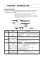
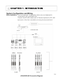
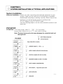
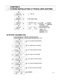
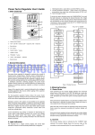
SC101
3 Axis Joystick
PTZ Controller
Please read the instructions carefully and keep this manual for future reference.
TABLE OF CONTENTS
•
CHAPTER 1 INTRODUCTION
In This Manual…………………………………………………07
Features………………………………………………………..07
Before installation……………………………………………..07
Hardware Overview…………………………………………...08
System Configuration and Wiring……………………………10
•
CHAPTER 2
SYSTEM INSTALLATION & TYPICAL APPLICATIONS
System Installation…………………………………………….11
PTZ SETUP…………………………………………………….11
MAIN SETUP…………………………………………………..12
JOYSTICK CALIBRATION…………………………………...13
EASY SETTING FUNCTION (E.S.F)……………………….14
SPECIFICATIONS ……………………………………………14
2
LIMITATION OF LIABILITY
THE INFORMATION IN THIS PUBLICATION IS BELIEVED TO BE ACCURATE IN
ALL RESPECTS, HOWEVER, WE CANNOT ASSUME RESPONSIBILITY FOR
ANY CONSEQUENCES RESULTING FROM THE USE THERE OF. THE
INFORMATION CONTAINED HEREIN IS SUBJECT TO CHANGE WITHOUT
NOTICE. REVISIONS OR NEW EDITIONS TO THIS PUBLICATION MAY BE
ISSUED TO IN CORPORATE SUCH CHANGES.
3
LIMITATION OF LIABILITY
TO REDUCE THE RISK OF FIRE OR ELECTRIC SHOCK, DO NOT EXPOSE THIS
PRODUCT TO RAIN OR MOISTURE.
DO NOT INSERT ANY METALLIC OBJECTS THROUGH THE VENTILATION GRILLS
OR OTHER OPENINGS ON THE EQUIPMENT
CAUTION
TO REDUCE THE RISK OF FIRE OR ELECTRIC SHOCK, DO NOT EXPOSE THIS
PRODUCT TO RAIN OR MOISTURE.
DO NOT INSERT ANY METALLIC OBJECTS THROUGH THE VENTILATION GRILLS
OR OTHER OPENINGS ON THE EQUIPMENT
CAUTION.
RISK OF ELECTRIC SHOCK
DO NOT OPEN
CAUTION : TO REDUCE THE RISK OF ELECTRIC
SHOCK, DO NOT REMOVE COVER(OR BACK).
NO USER SERVICEABLE PARTS INSIDE.
REFER SERVICING TO QUALIFIED SERVICE
PERSONNEL.
CAUTION
The lightning flash with arrow head symbol, within an equilateral triangle,
is intended to alert the user to the presence of uninsulated dangerous
voltage within the products enclosure that may be of sufficient
magnitude to constitute a risk of electric shock to persons.
The exclamation point within an equilateral triangle is intended to alert
the user to the presence of important operating and maintenance
(servicing) instruction in the literature accompanying the product.
4
IMPORTANT SAFEGUARDS
1. READ AND RETAIN INSTRUCTIONS
Read the instruction manual before operating the
equipment.
Retain the manual for future reference.
2. CLEANING
Turn the unit off and unplug from the power outlet
before cleaning. Use a damp cloth for cleaning.
Do not use harsh cleansers or aerosol cleaners.
3. ATTACHMENTS
Do not use attachments unless recommended by
manufactured as they may affect the functionality of the
unit and result in the risk of fire, electric shock or injur
y.
4. MOISTURE
Do not use equipment near water or other liquids.
5. ACCESSORIES
Equipment should be installed in a safe, stable locatio
n.
Any wall or shelf mounting accessory equipment shoul
d
be installed using the manufactures instructions. Care
should be used when moving heavy equipment. Quick
stops, excessive force, and uneven surfaces may
cause the equipment to fall causing serious injury to
persons and objects.
6. VENTILATION
Openings in the equipment, if any, are provided for
ventilation to ensure reliable operation of the unit and
to protect if from overheating. These openings must
not be blocked or covered
7. POWER SOURCES
The equipment should be operated only from the type
of power source indicated on the marking label.
If you are not sure of the type of power supplied at the
installation location, contact your dealer. For
equipment designed to operate from battery power,
refer to the operating instructions.
8. GROUNDING OR POLARIZATION
Equipment that is powered through a polarized plug
(a plug with one blade wider than the other) will fit
into the power outlet only one way. This is a safety
feature. If you are unable to insert the plug fully into
the outlet, try reversing the plug. Do not defeat the
safety purpose of the polarized plug.
9. CORD AND CABLE PROTECTION
Route power cords and cables in a manner to protect
them from damage by being walked on or pinched by
items places upon or against them.
10. LIGHTNING
For protection of the equipment during a lightning storm
or when it is left unattended and unused for long
periods of time, unplug the unit from the wall outlet.
Disconnect any antennas or cable systems that may be
connected to the equipment. This will prevent damage
to the equipment due to lightning or power line surges.
11. OVERLOADING
Do not overload wall outlets and extension cords as
this can result in a risk of fire or electric shock.
12. SERVICING
Do not attempt to service the video monitor or
equipment yourself as opening or removing covers may
expose you to dangerous voltage or other hazards.
Refer all servicing to qualified service personnel.
13. DAMAGE REQUIRING SERVICE
Unplug the equipment from the wall outlet and refer
servicing to qualified service personnel under the
following conditions:
A. When the power supply cord or the plug has been
damaged.
B. If liquid has spilled or objects have fallen into
the unit.
C. If the equipment has been exposed to water or
other liquids.
D. If the equipment does not operate normally by
following the operating instructions, adjust only thos
e
controls that are covered by the operating
instructions. Improper adjustment of other controls
may result in damage to the unit.
E. If the equipment has been dropped or the casing
damaged.
F. When the equipment exhibits a distinct change
in performance.
14. REPLACEMENT PARTS
When replacement parts are required, be sure the
service technician uses replacement parts specified by
the manufacturer or that have the same characteristics
as the original part. Unauthorized substitutions may
result in fire, electric shock, or other hazards.
Alternate Warning: If the equipment is powered
15. SAFETY CHECK
through a three way grounding type plug, a plug having Upon completion of any service or repairs to the
a third (grounding) pin, will only fit into a grounding-typ equipment, ask the service technician to perform safety
e
checks to verify that the equipment is in proper
power outlet. This is a safety feature.
5
Do not defeat the safety purpose of the grounding type operating condition.
16.
FIELD
INSTALLATION
plug. If your outlet does not have the grounding plug
The installation of equipment should be made by a
receptacle, contact your local electrician.
Qualified service person and should conform to all local
codes.
FCC COMPLIANCE STATEMENT
FCC INFORMATION : THIS EQUIPMENT HAS BEEN TESTED AND FOUND TO COMPLY
WITH THE LIMITS FOR A CLASS A DIGITAL DEVICE, PURSUANT TO PART 15 OF THE
FCC RULES. THESE LIMITS ARE DESIGNED TO PROVIDE REASONABLE PROTECTION
AGAINST HARMFUL INTERFERENCE WHEN THE EQUIPMENT IS OPERATED IN A
COMMECIAL ENVIRONMENT.
THIS EQUIPMENT GENERATES, USES, AND CAN RADIATE RADIO FREQUENCY
ENERGY AND IF NOT INSTALLED AND USED IN ACCORDANCE WITH THE
INSTRUCTION MANUAL, MAY CAUSE HARMFUL INTERFERENCE TO RADIO
COMMUNICATIONS. OPERATION OF THIS EQUIPMENT IN A RESIDENTIAL AREA IS
LIKELY TO CAUSE HARMFUL INTERFERENCE IN WHICH CASE THE USER WILL BE
REQUIRED TO CORRECT THE INTERFERENCE AT HIS OWN EXPENCE.
CAUTION : CHANGES OR MODIFICATIONS NOT EXPRESSLY APPROVED BY THE
PARTY RESPONSIBLE FOR COMPLIANCE COULD VOID THE USERS AUTHORITY TO
OPERATE THE EQUIPMENT.
THIS CLASS A DIGITAL APPARATUS COMLIES WITH CANADIAN ICES -003.
CET APPAREIL NUM IQUE DE LA CLASSE A EST CONFORME LA NORME NMB-003
DU CANADA.
CE COMPLIANCE STATEMENT
WARNING THIS IS A CLASS A PRODUCT. IN A DOMESTIC ENVIRONMENT THIS
PRODUCT MAY CAUSE RADIO INTERFERENCE IN WHICH CASE THE USER MAY
BE REQUIRED TO TAKE ADEQUATE MEASURES.
6
CHAPTER 1. INTRODUCTION
In This Manual
Overview - This manual covers the operation of the WTX-1200A keyboard.
SC101 Keyboard
This remote keyboard is an accessory for PTZ dome camera, etc
It allows the user to control from 1 to 255 cameras.
Features - Controls from 1 ~ 255 cameras.
- Multiple protocol supported in each channel (WDS,WCY, CYN, WSL, Pelco).
- RS 485/RS-422 communication (Tx : 3 port , Trx :1 port).
- Programmable user preferences. (preset, tour, group, etc.).
- Built-in 3-Axis proportional joystick
- Easy upload programmed data via serial communication port of PC.
- Built-in 2 lines character LCD.
- User password support.
- Designed for desktop use
- programmable transmission speed for each ID. (2.4~57.6kbps)
Note: units should be set to the communication protocol and the same baud rate.
Before installation
This keyboard system must be installed by qualified service and installation personnel.
Perform the following steps to install the keyboard system.
A. Unpack all components.
B. Place the keyboard in a convenient location.
Note: Carefully and completely read the manuals for each piece of equipment before
attempting to install and connect the equipment.
C. Decide on the configuration method.
D. Use one of the following sections to configure the wiring.
7
CHAPTER 1. INTRODUCTION
Hardware Overview
Hardware Components - This remote keyboard contains easy to use control keys on the
front and simple input and output connectors on the back
Control Buttons & Connection
- The unit provides the primary operator interface. Most
operations are one or two button presses.
The following Table contains a description for each buttons
on the keyboard and port of cable connection. Use Figure 1
and Figure 2 as a reference.
7
2
1
5
3
Number
< Figure 1 >
Description
ESC / POWER
Pressing the ESC/POWER button enters the Power on/off or escap
e key. Right description led on(red). Pressing it again exits the PO
WER OFF. (Push the
button (about 2~3 seconds) and then
POWER OFF)
LCD DISPLAY
Number
3
Displays Camera ID, Protocol, Function status, General status, etc.
Camera ID setting value change, PTZ setup(1+
Main setup(2+
)
),
Controller
Function keys
Hold : System locking (Unlocking : Input the Pass word 4 digit ****)
SHIFT/TURBO : SHIFT-Key for special function (Customize) /
TURBO -High Speed
AUX : External equipment on/off
SET : Ptz and main setup (1 +
), (2+
)
IRES CLOSE : Camera Iris close
IRIS OPEN : Camera Iris open
Function keys
F1 ~ MENU/AUTO : Function Keys
(Preset, Tour, Pattern, Scan, Auto).
MENU :Used for Camera (Pan/Tilt) Menu adjustment.
4
5
6
Button
1
2
4
8
CHAPTER 1. INTRODUCTION
Control buttons (continued)
Number
Button
Description
Camera Focus control
6
Camera Zoom control
*Before the mouse function use, you mouse be usb driver installed
(http://www.goodome.com/beta/english/e_download.php (filename:cdm20.zip)
Key operation method
Description
Push a mouse button(KEY 2~3 Seconds Push)
Mouse character description will be display
= Left button of Computer mouse
7
= Right button of Computer mouse
Reference key button
= Scroll key of Computer mouse ( Middle key).
(Simultaneously near far key push and joystick mov
e)
DVR Connection method
Push a mouse button(KEY Shortly Push)
Description
1
23 4
5
< Figure 2 >
Number
Button
Description
1
Telemetry Joystick BIt allows precise control of Pan/Tilt/Zoom
Joystick
2
3
4
5
DC 12V Input, 140mA
DV 12V Input
Universal Serial Bus Port, USB Mouse function
(External Equipment communication port)
USB PORT
TRx
Tx3 Tx2
RS-485
Program
Tx1
RS-485/RS-422 communications. (Tx/Rx : 3 port , Trx :1 port)
Download connector (For Pragram Update)
9
CHAPTER 1. INTRODUCTION
System Configuration and Wiring
Basic Installation - Use the Keyboard Configuration when only one keyboard is
connected to the controlled units.
Connect the RS-485 output port of Remote keyboard to RS-485
input port of the first controlled unit using the terminal block
10
<RS-422/RS-485 Connection Diagram>
CHAPTER 2.
SYSTEM INSTALLATION & TYPICAL APPLICATIONS
System Installation
Keyboard Installation - Before you start connecting the keyboard equipment to your
system, make sure the units to be controlled are completely
installed and everything is working correctly. Before use of this
keyboard, you should set the protocol and baud rate
(2.4~57.6kbps) in the PTZ SETUP mode.
Use the following steps to set the communication protocol and
baud rate.
PTZ SETUP
PTZ SETUO - PTZ Setup mode, select 1+
,(2~3 seconds)
setup screen allows you to change each device setting.
Note: The baud rate must be the same between the controlled unit and
the keyboard.
11
CHAPTER 2.
SYSTEM INSTALLATION & TYPICAL APPLICATIONS
MAIN SETUP
MAIN SETUP - Main Setup mode, select 2+
. (2~3 seconds)
setup screen allows you to change each device setting.
Note: The baud rate must be the same between the controlled unit and
the keyboard.
12
CHAPTER 2.
SYSTEM INSTALLATION & TYPICAL APPLICATIONS
JOYSTICK CALIBRATION
13
CHAPTER 2.
SYSTEM INSTALLATION & TYPICAL APPLICATIONS
EASY SETTING FUNCTION (E.S.F)
MAIN SETUP - Main Setup mode, select 2+
. (2~3 seconds)
setup screen allows you to change each device setting.
Note: The baud rate must be the same between the controlled unit and
the keyboard.
14
CHAPTER 2.
SYSTEM INSTALLATION & TYPICAL APPLICATIONS
EASY SETTING FUNCTION (E.S.F)
EASY SETTINF FUNCTION (Number key + Function key)
Number key + PSET/TOUR/PATT/SCAN/ E.S.F
is current position data (pan, tilt, focus, zoom data) save or call of Dome memory
DATA SAVE(SET)
(PSET button 2 seconds push)
Current Position Saved Preset No 2
(TOUR button 2 seconds push)
TOUR MENU CALL OF DOME
DATA CALL(GOTO)
(PSET button push)
No 2 Preset position execution
(TOUR button push)
No 3 Tour Execution of DOME
SPECIFICATIONS
Model
SC101
Interface: RS-485 (Tx 3 port, Trx 1 port) P
Keyboard Communication
an/Tilt operating distance :4000 ft No 24 AWG wire
Protocol: Multiple (Pelco-D, etc. ) (Baud rate selectable)
Connector Type Date
Keyboard Keypad
TERMINAL BLOCK(8p)
Rubber button
Numeric keypad and camera function key
Joystick
Stick 3-axis, variable speed with zoom
Input Valtage
12V DC or 9V batt (battery mode)
Power Consumption
Max.140mA
LCD Display
Graphic display : 16 * 2 Graphic display
Operating Temperature
0 to 45
Humidity
10% -70 % non-condensing
Dimension & Weight
280(W) x 174(D) x 92(H), Net : 0.7 Kg Gross: 1.7Kg
KEYBOARD, ADAPTOR
Packing include
Packing include : BATT 9V(Alkaline), USB CABLE,
MANUAL, TERMINAL BLOCK(8p)
15
MEMO
NY: 55 Mall Drive Commack, NY 11725 • TEL: 1 (800) 422-6707 • (631) 864-9700 • FAX: (631) 543-5426
CA: 20521 Earl Street Torrance, CA 90503 • TEL: 1 (800) 888-0131 • (310) 793-1500 • FAX: (310) 793-1506
www.computarganz.com © 2010 CBC (AMERICA) Corp. All Rights Reserved.
16