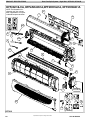
1
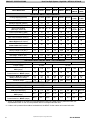
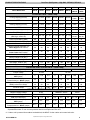
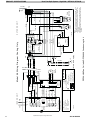
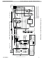
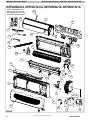
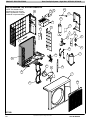
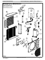
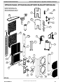
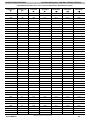
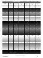
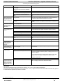
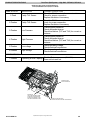
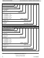
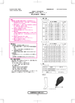
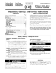
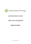
TECHNICAL SUPPORT MANUAL
Duct Free Split Systems
DFF2A/H and DFC2A/H
Safety Labeling and Signal Words
DANGER, WARNING, CAUTION, and
NOTE
The signal words DANGER, WARNING, CAUTION, and NOTE are used to identify levels of hazard seriousness. The signal word DANGER is only
used on product labels to signify an immediate hazard. The signal words WARNING, CAUTION, and
NOTE will be used on product labels and throughout this manual and other manuals that may apply
to the product.
DANGER -- Immediate hazards which will result in
severe personal injury or death.
WARNING -- Hazards or unsafe practices which
could result in severe personal injury or death.
CAUTION -- Hazards or unsafe practices which
may result in minor personal injury or product or
property damage.
Signal Words in Manuals
The signal word WARNING is used throughout this
manual in the following manner:
!
WARNING
WARNING
The signal word CAUTION is used throughout this
manual in the following manner:
!
CAUTION
Signal Words on Product Labeling
Signal words are used in combination with colors
and/or pictures on product labels.
NOTE -- Used to highlight suggestions which will
result in enhanced installation, reliability, or operation.
TABLE OF CONTENTS
Technical Data . . . . . . . . . . . . . . . . . . . . . . . . . . . . . . . . . 2
Wiring Diagrams . . . . . . . . . . . . . . . . . . . . . . . . . . . . . . . 4
09 & 12 Exploded Drawings & Parts . . . . . . . . . . . . . 14
18 & 24 Exploded Drawings & Parts . . . . . . . . . . . . . 20
30 & 36 Exploded Drawings & Parts . . . . . . . . . . . . . 25
Dual 18 & 24 Exploded Drawings . . . . . . . . . . . . . . . . 29
Temperature to Resistance Conversion . . . . . . . . . . . 33
Troubleshooting . . . . . . . . . . . . . . . . . . . . . . . . . . . . . . . 36
Dip Switch Settings . . . . . . . . . . . . . . . . . . . . . . . . . . . . 37
Model Number Identification . . . . . . . . . . . . . . . . . . . . 38
!
WARNING
PERSONAL INJURY, AND/OR PROPERTY DAMAGE HAZARD
Failure to carefully read and follow this warning
could result in equipment malfunction, property
damage, personal injury and/or death.
Installation or repairs made by unqualified persons could result in equipment malfunction, property damage, personal injury and/or death.
The information contained in this manual is intended for use by a qualified service technician familiar with safety procedures and equipped with
the proper tools and test instruments.
Installation must conform with local building
codes and with the National Electrical Code
NFPA70 current edition or Canadian Electrical
Code Part 1 CSA C.22.1.
421 04 9500 00 11/2006
PRODUCT SPECIFICATIONS
Duct Free Split System -- High Wall: DFF2A/H, DFC2A/H
Outdoor Model Size
09J1A
12J1A
18K1A
24K1A
30K1A
36K1A
18J2A
24J2A
Indoor Model Size
09J1A
12J1A
18J1A
24K1A
30K1A
36K1A
2x
09J1A
2x
12J1A
PHYSICAL DATA - Air Conditioner
Cooling Capacity (BTU/hr)
9,000
11,600
19,000
22,800
29,000
33,000
2x
9,000
2x
11,600
SEER
13.0
13.0
13.0
13.0
14.0
13.0
13.0
13.0
Moisture Removal (pints/hr)
2.6
4.5
5.3
5.0
7.0
8.0
2 x 2.6
2 x 4.5
Indoor Fan CFM (High speed)
350
400
670
726
860
860
2 x 350
2 x 400
Indoor Sound Rating
(dBA High -- dBA Low)
55 -- 45
60 -- 48
62 -- 50
64 -- 50
65 -- 53
65 -- 53
2x
55--45
2x
60--48
Outoor Sound Rating (dBA)
68
72
74
76
76
76
74
76
Liquid Line Connection Size (in.)
1/4
1/4
3/8
3/8
3/8
3/8
2 x 1/4
2 x 1/4
Vapor Line Connection Size (in.)
1/2
1/2
5/8
5/8
3/4
3/4
2 x 1/2
2 x 1/2
Maximum Vertical Separation (ft.)
Indoor Higher than Outdoor
30
30
30
65
65
65
30
30
Maximum Vertical Separation (ft.)
Indoor Lower than Outdoor
30
30
30
75
75
75
30
30
Maximum Line--set Length (ft.)
50
50
50
130
130
130
50
50
Factory Charge R--22 (lbs.) *
2.7
3.1
4.1
4.2
6.06
5.9
2 x 2.7
2 x 3.1
* Units are factory charged for 25’ of line set. Add or remove .3oz. of charge per foot if line set length is different.
Net Weight, Outdoor (lbs.)
73
114
136
187
198
198
136
228
Net Weight, Indoor (lbs.)
19
19
27.5
27.5
51
51
2 x 19
2 x 19
OUTDOOR ELECTRICAL DATA - Air Conditioner
Required Supply Voltage
115--1--60 AC
Control Voltage
208/230--1--60 AC
30 VDC
115--1--60 AC
24 VAC
Minimum Circuit Ampacity -MCA (amps)
9
11.6
10.7
11
13
15.6
19.8
24.6
Maximum OverCurrent
Protective device -- MOCP (amps)
15
20
20
20
25
30
25
30
Compressor RLA (Run Load Amps)
LRA (Locked Rotor Amps)
6.1
42
7.6
58
6.5
42
8.6
60
10.0
76
12.9
73
7.2
42
9.3
58
Fan Motor Amps
0.9
1
0.88
0.87
0.94
0.94
1
1
INDOOR ELECTRICAL DATA -- Air Conditioner
Required Supply Voltage
30 DC 1
Control Voltage
30 VDC
30 DC 1
208/230--1--60 AC
24 VAC
FLA (Full Load Amps)
1.8
1.8
2.4
0.6
0.6
0.6
2 x 1.8
2 x 1.8
Minimum Circuit Ampacity -MCA (amps)
N/A 1
N/A 1
N/A 1
0.46
0.55
0.55
N/A 1
N/A 1
Maximum OverCurrent
Protective device -- MOCP (amps)
N/A 1
N/A 1
N/A 1
15 2
15 2
15 2
N/A 1
N/A 1
1. 30VDC is generated by the outdoor unit and delivered through low voltage wiring to power the indoor unit.
Separate disconnect or over--current protection device not required at indoor unit.
2. If indoor unit is powered from outdoor terminal block, the MOCP for the outdoor unit covers both units.
2
Specifications subject to change without notice.
421 04 9500 00
PRODUCT SPECIFICATIONS
Duct Free Split System -- High Wall: DFF2A/H, DFC2A/H
Outdoor Model Size
09J1A
12J1A
18K1A
24K1A
30K1A
36K1A
18J2A
24J2A
Indoor Model Size
09J1A
12J1A
18J1A
24K1A
30K1A
36K1A
2x
09J1A
2x
12J1A
PHYSICAL DATA - Heat Pump
Cooling Capacity (BTU/hr)
9,000
11,600
19,000
22,800
29,000
33,000
2x
9,000
2x
11,600
SEER
13.0
13.0
13.0
13.0
14.0
13.0
13.0
13.0
Heating Capacity (BTU/hr)
8,600
11,800
18,300
22,600
28,000
32,000
2x
8,600
2x
11,800
HSPF
7.7
7.7
7.7
7.7
8.4
8.4
7.7
7.7
Moisture Removal (pints/hr)
2.6
4.5
5.3
5.0
7.0
8.0
2 x 2.6
2 x 4.5
Indoor Fan CFM (High speed)
350
400
670
726
860
860
2 x 350
2 x 400
Indoor Sound Rating
(dBA High -- dBA Low)
55 -- 45
60 -- 48
62 -- 50
64 -- 50
65 -- 53
65 -- 53
2x
55--45
2x
60--48
Outoor Sound Rating (dBA)
68
72
74
76
76
76
74
76
Liquid Line Connection Size (in.)
1/4
1/4
3/8
3/8
3/8
3/8
2 x 1/4
2 x 1/4
Vapor Line Connection Size (in.)
1/2
1/2
5/8
5/8
3/4
3/4
2 x 1/2
2 x 1/2
Maximum Vertical Separation (ft.)
Indoor Higher than Outdoor
30
30
30
65
65
65
30
30
Maximum Vertical Separation (ft.)
Indoor Lower than Outdoor
30
30
30
75
75
75
30
30
Maximum Line--set Length (ft.)
50
50
50
130
130
130
50
50
Factory Charge R--22 (lbs.) *
2.7
3.1
4.1
4.2
6.06
5.9
2 x 2.7
2 x 3.1
* Units are factory charged for 25’ of line set. Add or remove .3oz. of charge per foot if line set length is different.
Net Weight, Outdoor (lbs.)
73
114
136
187
198
198
136
228
Net Weight, Indoor (lbs.)
19
19
27.5
27.5
51
51
2 x 19
2 x 19
OUTDOOR ELECTRICAL DATA - Heat Pump
Required Supply Voltage
115--1--60 AC
Control Voltage
208/230--1--60 AC
30 VDC
115--1--60 AC
24 VAC
Minimum Circuit Ampacity -MCA (amps)
9
11.6
10.7
11
13
15.6
19.8
24.6
Maximum OverCurrent
Protective device -- MOCP (amps)
20
20
20
20
25
30
25
30
Compressor RLA (Run Load Amps)
LRA (Locked Rotor Amps)
6.1
42
7.6
58
6.5
42
8.6
60
10.0
76
12.9
73
7.2
42
9.3
58
Fan Motor Amps
0.9
1
0.88
0.87
0.94
0.94
1
1
INDOOR ELECTRICAL DATA - Heat Pump
Required Supply Voltage
30 DC 1
Control Voltage
30 VDC
30 DC 1
208/230--1--60 AC
24 VAC
FLA (Full Load Amps)
1.8
1.8
2.4
0.6
0.6
0.6
2 x 1.8
2 x 1.8
Minimum Circuit Ampacity -MCA (amps)
N/A 1
N/A 1
N/A 1
0.46
0.55
0.55
N/A 1
N/A 1
Maximum OverCurrent
Protective device -- MOCP (amps)
N/A 1
N/A 1
N/A 1
15 2
15 2
15 2
N/A 1
N/A 1
1. 30VDC is generated by the outdoor unit and delivered through low voltage wiring to power the indoor unit.
Separate disconnect or over--current protection device not required at indoor unit.
2. If indoor unit is powered from outdoor terminal block, the MOCP for the outdoor unit covers both units.
421 04 9500 00
Specifications subject to change without notice.
3
J1 2
1
3
K
8
K
7
7 1 53 A
CC
--C om p res sor C ap a citor
C O MP --C om presso r
FC
--F a n C a p a c it o r
G N D --G ro u nd
TB
--T e rm i n a l B l o c k
TH
--T h e r m i s t o r
T AC 670 co ntr ol
6
4
5
1
J1 1
2
3
4
5
J8
J1 8
K9
J1 4
K
1
K
2
K5
K
6
J7
TA C 6 71 Ma in Bo ard
STEPPER
MO TO R
J
6
TH2
WH
FA N 3
F AN 2
BLK
RED
F A N 1 BLU E
+ 30 V
+ 12 V RED
--12V B LK
C OM P .
RVS
J5
1 23
6
5
4
3
2
1
J4
J1
M
L EGEND
W HT+ 12 VDC
YEL VSP
BLK DC RTN
B L DC
MOTOR
GND
RED + 30 VDC
GR/YEL
6
1
2
3
4
5
TB
421 04 9500 00
L1
N
5
6
**R E D
**GR EE N
3
4
2
1
**W H
**BLK
VAC
G RD
GND
DC RTN
M a in A C S u p p ly
115
L1 N
HLTV
+3 0 VD C
***RED
D C R TN
CO MP 1
RVS
H.L.T.V
FAN
D C R T N ( --)
DC O u t ( + )
T A C 67 3
R elay Board
4
5
2
3
1
RV S
CO MP 1
J1
FAN
TB
RV S
H.L.T.V
FAN
TB
1
AC
IN
BLK
C
R
COMP.
S
CC
BLK
FC
*O R
BLK
*BLU E
BLK
DC
R TN
GRD
L1
FAN
MOTOR
247915
WHT
BLK
N
GR/Y EL
TB
Notes:
1. If any of the original wire furnished must be replaced, it must
be replaced with Type 90 degrees C wire or its equivalent.
2. Wire in accordance with National Electrical Code (NEC) and
local codes.
3. Thermistor wiring cable 32 ft. long provided with indoor unit.
4. Compressor and fan motors are protected by internal thermal
overloads.
***G R EEN
L1 BR
N BLUE
FUSE 6A
3 0V DC
Po w e r Su p p l y
DC
Out
*** G R/Y EL
G R/YEL
* B LU E
* BR
GR EEN
GR EEN
P H --A C
C O MP 1
K1
K2
K3
K4
DFF2AH09 Fan Coil with DFC2A309 Condensing Unit
***
--1 6 A W G
**
--1 4 A W G
*
--1 2 A W G
A L L O TH E R W I R E S 1 8 A W G
--S p l i c e
--Te r m in a l (U n m a r k e d )
F ac to r y W i r i n g
F i e ld C o n t r o l W i r in g
F ie ld P o w e r W i r in g
A c c e s s o r y o r O p t i o n a l W ir in g
T AC 672 A
M ot or C on tro l
5
4
3
2
1
J3
1
3
RED
H.L .T.V
GR EE N
WH
OR
F AN
BLK
YEL
*G R /Y EL
TH1
*BR
*B L U E
OUTDOOR UNIT
*BLK
M o d el 09 W i r i n g D i a g r a m C o o l i n g O n l y
*BR
*B R
Specifications subject to change without notice.
WHT
BRN
INDOOR UNIT
G R /Y EL
B LK
4
OR
BRN
WH
YEL/G R
RED
BLK
PRODUCT SPECIFICATIONS
Duct Free Split System -- High Wall: DFF2A/H, DFC2A/H
J12
1
3
K
8
K
7
FA N 2
71 30 F
C C --Com pressor C apa citor
C OMP --Compressor
FC
--Fa n C a pa cit o r
GN D --Grou n d
RVS --Re versing Valve Sole noid
H LTV --He ating Low Tem p. Valve
TB
--Te rm ina l B lo c k
TH
--T h e rm i st o r
T A C 6 7 0 c o n tr o l
WH
BLK
RE D
FA N 1 BL UE
+ 3 0V
+1 2 V RED
--12V BLK
COMP.
RVS
H. L . T . V
FAN
6 FA N 3
4
5
1
J11
2
3
4
5
J8
J18
K9
J14
K
1
K
2
K5
K
6
J7
TAC 67 1 Main Board
STEPPER
M OTO R
J
6
TH3
2
3
4
5
6
1
J4
J1
12 3
B L DC
MOTOR
M
LEGEND
WHT+ 12 VDC
YEL VSP
RED + 30 VDC
BLK DC RTN
G ND
5
**G REEN
**YEL
**W H
**O R
* * R ED
**BLK
N
L1
VAC
FAN
GRD
GND
DC R TN
+ 30 VD C
HLTV
C OMP 1
RVS
***RED
M a in A C S u p p ly
115
L1 N
1
2
3
4
5
6
TB
RVS
COMP 1
D C R TN
FAN
H.L.T.V
D C R TN ( --)
D C O u t (+ )
TAC 67 3
Relay Board
4
5
1
2
3
J1
BLK
AC
IN
30VDC
Po w er Su p p l y
DC
O ut
RVS
H.L.T.V
FAN
BLK
C
R
COMP.
S
FC
*O R
BLK
*BLUE
BLK
RVS
DC
RT N
GRD
L1
FAN
MOTOR
247915
N
WHT
BLK
G R /Y E L
Notes:
1. If any of the original wire furnished must be replaced, it must
be replaced with Type 90 degrees C wire or its equivalent.
2. Wire in accordance with National Electrical Code (NEC) and
local codes.
3. Thermistor wiring cable 32 ft. long provided with indoor unit.
4. Compressor and fan motors are protected by internal thermal
overloads.
***GREEN
L1 B R
CC
HLTV
BLK
TH3
OUTDOOR UNIT
N BLUE
FUSE 6A
* * * G R / YE L
G R/Y E L
* B LUE
G R E EN
G R E EN
* BR
P H --A C
COM P 1
K1
K2
K3
K4
TB
1
DFF2HH09 Fan Coil with DFC2H309 Condensing Unit
***
--1 6 A W G
**
--1 4 A W G
*
--1 2 A W G
A LL O T H E R W I R E S 1 8 A W G
--S p li c e
--T erm in a l (U n m a r ke d )
F ac t or y W i r i ng
F ie l d C o n t r o l W ir in g
F i e ld P o w e r W i r in g
A c ce s so r y o r O p t io n a l W i r in g
T A C 6 72 A
Moto r Con trol
3
4
5
1
2
J3
1
3
J5
GR/YEL
TB
1
2
WH
3
OR
4
R ED
5
GREEN
6
BLK
YEL
*GR/YEL
TH2
*BR
*BLUE
TH1
Mo d el 09 W i r i n g D i ag r am Heat Pu m p
*BR
*BR
*BLK
Specifications subject to change without notice.
WHT
BRN
INDOOR UNIT
GR/YEL
BLK
421 04 9500 00
OR
BRN
WH
YEL/GR
RED
BLK
GR/YEL
TB
PRODUCT SPECIFICATIONS
Duct Free Split System -- High Wall: DFF2A/H, DFC2A/H
1
3
K
7
7154A
CC --Compressor Capacitor
COMP--Compressor
FC
--Fan Capacitor
GND --Ground
TB
--Terminal Block
TH
--Thermistor
TAC 670 control
FAN 2RED
FAN 1BLUE
+30V WH
+12V RED
--12V BLK
RVS
COMP.
H.L.T.V
FAN
6 FAN 3 BLK
4
5
1
J11
3
2
4
5
J8
J18
K9
K
8
J14
K
1
K
2
K
6
K5
J7
TAC 671 Main Board
J12
STEPPER
MOTOR
J
6
TH2
1
2
3
4
5
6
J4
J1
123
M
LEGEND
WHT+ 12 VDC
YEL VSP
BLDC
MOTOR
GND
RED + 30 VDC
BLK DC RTN
1
2
3
4
5
6
421 04 9500 00
**GREEN
**RED
**WH
**BLK
N
L1
1
2
3
4
5
6
RVS
COMP 1
DC RTN
FAN
HLTV
***RED
DC RTN ( --)
DC Out (+)
TAC 673
Relay Board
1
2
3
4
5
J1
Main AC Supply
L1 N
115 VAC
GND
DC RTN
+30 VDC
HLTV
COMP 1
RVS
FAN
TB
AC
IN
30VDC
Power Supply
DC
Out
RVS
H.L.T.V
FAN
TB
1
C
R
COMP.
S
123456
FAN
MOTOR
WHT
DC
RTN
GRD
N L1
Notes:
1. If any of the original wire furnished must be replaced, it must
be replaced with Type 90 degrees C wire or its equivalent.
2. Wire in accordance with National Electrical Code (NEC) and
local codes.
3. Thermistor wiring cable 32 ft. long provided with indoor unit.
4. Compressor and fan motors are protected by internal thermal
overloads.
***GREEN
L1 BR
CC
FC
*OR
BLK
BLK
*BLUE
BLK
OUTDOOR UNIT
BLK
BLK
N BLUE
FUSE 6A
* BLUE
GR/YEL
*** GR/YEL
GREEN
GREEN
* BR
PH-- AC
COMP 1
K1
K2
K3
K4
DFF2AH12 Fan Coil with DFC2A312Condensing Unit
***
--16 AWG
**
--14 AWG
*
--12 AWG
ALL OTHER WIRES 18 AWG
--Splice
--Terminal (Unmarked)
Factory Wiring
Field Control Wiring
Field Power Wiring
Accessory or Optional Wiring
TAC 672 B
Motor Control
1
2
3
4
5
J3
1
3
J5
GR/YEL
BLK
YEL
WH
OR
RED
GREEN
TB
*BR
*BLUE
*GR/YEL
TH1
Model 12 Wiring Diagram Cooling Only
*BR
*BR
GR/YEL
BLK
INDOOR UNIT
*BLK
WHT
BRN
Specifications subject to change without notice.
BLK
6
WH
BRN
RED
YEL/GR
GR/YEL
TB
PRODUCT SPECIFICATIONS
Duct Free Split System -- High Wall: DFF2A/H, DFC2A/H
1
3
4 FAN 2 RED
6 FAN 3 BLK
K9
K7
CC --Compressor Capacitor
COMP--Compressor
FC
--Fan Capacitor
GND --Ground
RVS --Reversing Valve Solenoid
HLTV --Heating Low Temp. Valve
TB
--Terminal Block
TH
--Thermistor
TAC 670 control
7152A
WH
5 FAN 1BLUE
J11
1 +30V
+12V RED
--12V BLK
COMP.
RVS
K8
J14
K2
K1
3
2
4 H.L.T.V
K6
FAN
K5
J8
J18
TH3
5
J7
TAC 671 Main Board
J12
STEPPER
MOTOR
J
6
TH2
1
2
3
4
5
6
J4
J1
123
M
LEGEND
WHT+ 12 VDC
YEL VSP
BLDC
MOTOR
GND
RED + 30 VDC
BLK DC RTN
1
2
3
4
5
6
**GREEN
**BLK
**YEL
**WH
**OR
**RED
N
L1
1
2
3
4
5
6
J1
1
2
3
4
5
RVS
COMP 1
DC RTN
FAN
HLTV
***RED
DC RTN ( --)
DC Out (+)
TAC 673
Relay Board
Main AC Supply
L1 N
115 VAC
GND
DC RTN
+30 VDC
HLTV
COMP 1
RVS
FAN
TB
BLK
AC
IN
30VDC
Power Supply
DC
Out
RVS
H.L.T.V
FAN
TB 1
C
R
COMP.
S
FC
*OR
BLK
FAN
MOTOR
123456
WHT
N L1
DC
RTN
GRD
Notes:
1. If any of the original wire furnished must be replaced, it must
be replaced with Type 90 degrees C wire or its equivalent.
2. Wire in accordance with National Electrical Code (NEC) and
local codes.
3. Thermistor wiring cable 32 ft. long provided with indoor unit.
4. Compressor and fan motors are protected by internal thermal
overloads.
***GREEN
L1 BR
CC
HLTV
BLK
GR/YEL
BLK
*BLUE
RVS
TH3
OUTDOOR UNIT
BLK
BLK
N BLUE
FUSE 6A
*** GR/YEL
* BLUE
GR/YEL
GREEN
GREEN
* BR
PH-- AC
COMP 1
K1
K2
K3
K4
DFF2HH12 Fan Coil with DFC2H312 Heat Pump
***
--16 AWG
**
--14 AWG
*
--12 AWG
ALL OTHER WIRES 18 AWG
--Splice
--Terminal (Unmarked)
Factory Wiring
Field Control Wiring
Field Power Wiring
Accessory or Optional Wiring
TAC 672 B
Motor Control
1
2
3
4
5
J3
1
3
J5
GR/YEL
BLK
YEL
WH
OR
RED
GREEN
TB
*BR
*BLUE
*GR/YEL
TH1
Model 12 Wiring Diagram Heat pump
*BR
*BR
GR/YEL
BLK
INDOOR UNIT
*BLK
WHT
BRN
Specifications subject to change without notice.
BLK
421 04 9500 00
WH
BRN
RED
YEL/GR
GR/YEL
TB
PRODUCT SPECIFICATIONS
Duct Free Split System -- High Wall: DFF2A/H, DFC2A/H
7
1
3
K
7
7155A
CC --Compressor Capacitor
COMP--Compressor
FC
--Fan Capacitor
GND --Ground
TB
--Terminal Block
TH
--Thermistor
TAC 670 control
FAN 2 RED
FAN 1 BLUE
+30V WH
+12V RED
--12V BLK
COMP.
RVS
H.L.T.V
FAN
6 FAN 3 BLK
4
5
1
J11
3
2
4
5
J8
J18
K9
K
8
J14
K
1
K
2
K
6
K5
J7
TAC 671 Main Board
J12
STEPPER
MOTOR
J
6
TH2
1
2
3
4
5
6
J4
J1
123
BLDC
MOTOR
M
LEGEND
WHT+ 12 VDC
YEL VSP
RED + 30 VDC
BLK DC RTN
GND
**GREEN
**RED
**WH
**BLK
L2
L1
1
2
3
4
5
6
GND
DC RTN
+30 VDC
HLTV
COMP 1
RVS
FAN
TB
J1
1
2
3
4
5
RVS
COMP 1
DC RTN
FAN
HLTV
421 04 9500 00
AC
IN
30VDC
Power Supply
DC
Out
RVS
H.L.T.V
FAN
TB 1
BLK
CC
BLK
C
R
COMP.
S
FC
*OR
BLK
BLK
*BLUE
FAN
MOTOR
123456
DC
GND
L1L2 RTN
WHT
BLK
OUTDOOR UNIT
Notes:
1. If any of the original wire furnished must be replaced, it must
be replaced with Type 90 degrees C wire or its equivalent.
2. Wire in accordance with National Electrical Code (NEC) and
local codes.
3. Thermistor wiring cable 32 ft. long provided with indoor unit.
4. Compressor and fan motors are protected by internal thermal
overloads.
***GREEN
L1 BR
L2 BLUE
FUSE 6A
* BLUE
GR/YEL
*** GR/YEL
GREEN
GREEN
* BR
PH-- AC
COMP 1
K1
K2
K3
K4
DFF2AH18 Fan Coil with DFC2A318 Condensing Unit
DC RTN ( --)
DC Out (+)
TAC 673
Relay Board
***RED
Main AC Supply
***
--16 AWG
**
--14 AWG
*
--12 AWG
ALL OTHER WIRES 18 AWG
--Splice
--Terminal (Unmarked)
Factory Wiring
L1L2
Field Control Wiring
208\230
VAC
Field Power Wiring
Accessory or Optional Wiring
TAC 672 A
Motor Control
1
2
3
4
5
J3
1
3
J5
GR/YEL
1
2
3
4
5
6
TB
BLK
YEL
WH
OR
RED
GREEN
*BR
*BLUE
*GR/YEL
TH1
Model 18 Wiring Diagram Cooling Only
*BR
*BR
GR/YEL
BLK
INDOOR UNIT
*BLK
WHT
BRN
Specifications subject to change without notice.
BLK
8
WH
BRN
RED
YEL/GR
GR/YEL
TB
PRODUCT SPECIFICATIONS
Duct Free Split System -- High Wall: DFF2A/H, DFC2A/H
J
6
1
3
FAN
4 FAN 2 RED
FAN 3 BLK
K9
K
7
7137F
CC --Compressor Capacitor
COMP--Compressor
FC
--Fan Capacitor
GND --Ground
RVS --Reversing Valve Solenoid
HLTV --Heating Low Temp. Valve
TB
--Terminal Block
TH
--Thermistor
TAC 670 control
6
5 FAN 1 BLUE
WH
+12V RED
--12V BLK
COMP.
J11
1 +30V
2
4 H.L.T.V
3 RVS
5
J8
J18
TH3
K
8
J14
K
1
K
2
K
6
K5
J7
TH2
TAC 671 Main Board
J12
STEPPER
MOTOR
TH1
1
2
3
4
5
6
J4
J1
123
BLDC
MOTOR
M
LEGEND
WHT+ 12 VDC
YEL VSP
RED + 30 VDC
BLK DC RTN
GND
**GREEN
**BLK
**YEL
**WH
**OR
**RED
L2
L1
1
2
3
4
5
6
1
2
3
4
5
J1
DC RTN
***RED
DC RTN ( --)
DC Out (+)
GREEN
GREEN
* BR
PH-- AC
COMP 1
K1
K2
K3
K4
AC
IN
30VDC
Power Supply
DC
Out
RVS
H.L.T.V
FAN
TB
1
BLK
CC
HLTV
BLK
C
R
COMP.
S
FC
*OR
BLK
FAN
MOTOR
123456
GND
DC
L1L2 RTN
WHT
BLK
GR/YEL
BLK
*BLUE
RVS
TH3
Notes:
1. If any of the original wire furnished must be replaced, it must
be replaced with Type 90 degrees C wire or its equivalent.
2. Wire in accordance with National Electrical Code (NEC) and
local codes.
3. Thermistor wiring cable 32 ft. long provided with indoor unit.
4. Compressor and fan motors are protected by internal thermal
overloads.
***GREEN
L1 BR
L2 BLUE
FUSE 6A
* BLUE
GR/YEL
*** GR/YEL
RVS
COMP 1
FAN
HLTV
TAC 673
Relay Board
Main AC Supply
L1 L2
208\230 VAC
GND
DC RTN
+30 VDC
HLTV
COMP 1
RVS
FAN
TB
DFF2HH18 Fan Coil with DFC2H318 Heat Pump
***
--16 AWG
**
--14 AWG
*
--12 AWG
ALL OTHER WIRES 18 AWG
--Splice
--Terminal (Unmarked)
Factory Wiring
Field Control Wiring
Field Power Wiring
Accessory or Optional Wiring
TAC 672 A
Motor Control
1
2
3
4
5
J3
1
3
J5
GR/YEL
1
2
3
4
5
6
TB
BLK
YEL
WH
OR
RED
GREEN
*BR
*BLUE
*GR/YEL
OUTDOOR UNIT
WHT
BRN
Model 18 Wiring Diagram Heat Pump
*BLK
GR/YEL
BLK
INDOOR UNIT
*BR
*BR
Specifications subject to change without notice.
BLK
421 04 9500 00
WH
BRN
RED
YEL/GR
GR/YEL
TB
PRODUCT SPECIFICATIONS
Duct Free Split System -- High Wall: DFF2A/H, DFC2A/H
9
J9
SWEEP
MOTOR
(OPTION)
J1
DISPLAY
CONTR.
J11
FANT BLK
K7
BLUE
J11--4
J11--6
FANL RED
J11--5
OR
FAN
MOTOR
BR
K4
K3
K2
K1
7136D
421 04 9500 00
BR
FC
L1 L2
WH
RED
GREEN
BLK
YEL
Main AC Supply
208\230 VAC
GND
L1
L2
1
2
3
4
5
Factory Wiring
Field Control Wiring
Field Power Wiring
Accessory or Optional Wiring
LEGEND
FAN
5
COMP.
ECONO.
4
RVS
3
COMP.F
ULL
2
COMMON
24 VAC
1
J3
BLK
YEL
WH
RED
GREEN
1
2
3
4
5
J1
1
2
3
4
5
L1 L2
Main AC Supply
208\230 VAC
GND
L2
L1
COMMON
RVS
COMP.FULL
COMP. ECONO.
FAN
5
FAN
*BLK
*BLK
GR/YEL
*BLUE
*BR
FUSE 6A
COMP.
FULL
208-- 230
AC
2
RVS
3
COMP.
ECONO.
L1
A1
A2
T1
L2
CH
C SR
COMP.
CC
PTCR
BLUE
*BLUE
A2
T1
(TB)
CONTACTOR 2A1L1
*BR
WHT
BL
K
BR
RED
RVS
T2
BLK
O.L.
BLUE
ESV
(TB)
CONTACTOR 1
K1
K2
K3
K4
4
J2
24V OUTDOOR BOARD
TB
FC
BLK
123456
123456
FAN
MOTOR
L2
T2
OUTDOOR UNIT
TH3
DFF2AH/HH 24 Fan Coil with DFC2A/H3 24 Condensing Unit/Heat Pump
CC --Compressor Capacitor O.L.-- overload (option)
COMP--Compressor
*
--12 AWG
FC
--Fan Capacitor
all other wires 18 AWG
RVS--Reversing Valve Solenoid
-- Splice
CH -- crankcase heater
HLTV --Heating Low Temp. Valve
ESV-- electrical solenoid valve
TB
--Terminal Block
PTCR -- hard starting relay
TH
--Thermistor
GND -- ground
TAC --670 C
FO1~
J11--2
WH
FANH BLUE
FAN0
1
+12VDC
2
RVS
3
COMP.
ECONO.
4
FAN
5
COMP.
FULL
J1
K9
K8
J11--1
24 VAC
J2
1
2
*GR/YEL
*BR
*BLUE
24V INDOOR BOARD
*GR/YEL
J8
*BR
*BLUE
J7
*BLK
*BLK
J6
BLUE
FUSE 6A
Model 24 wiring Diagram
WHT
BLUE
*BLUE
TB
*BR
TH3
BLUE
TH2
*BR
TH1
*BLK
WHT
BRN
INDOOR UNIT
*BLK
Specifications subject to change without notice.
BLK
10
WHT
BRN
RED
YEL/GR
PRODUCT SPECIFICATIONS
Duct Free Split System -- High Wall: DFF2A/H, DFC2A/H
J9
SWEEP
MOTOR
(OPTION)
J1
DISPLAY
CONTR.
7134C
OR
BR
BR
FC
L1 L2
WH
RED
GREEN
BLK
YEL
Main AC Supply
208\230 VAC
GND
L1
L2
1
2
3
4
5
Factory Wiring
Field Control Wiring
Field Power Wiring
Accessory or Optional Wiring
LEGEND
FAN
5
COMP.
ECONO.
4
RVS
3
COMP.F
ULL
2
COMMON
24 VAC
YEL
WH
RED
GREEN
BLK
1
2
3
4
5
1
2
3
4
5
J1
Main AC Supply
208\230 VAC
L1 L2
GND
L2
L1
COMMON
COMP. ECONO.
RVS
COMP. FULL
FAN
*BLK
*BLK
GR/YEL
*BLUE
*BR
FUSE 6A
COMP.
FULL
208-- 230
AC
2
RVS
3
COMP.
ECONO.
5
FAN
J2
4
(TB)
CONTACTOR 1
K1
K2
K3
K4
24V OUTDOORBOARD
L1
O.L.
BLUE
A1
A2
T1
L2
T2
BLK
BLK
CH
RC S
L1
BLUE
A1
A2
T1
COMP.
CC
PTCR
CONTACTOR 2
(TB)
*BLUE
*BR
WHT
BR
RED
RVS
TB
FC
BLK
12 3456
123456
FAN
MOTOR
L2
T2
O U T D O O R U NI T
DFF2AH/DFF2HH 30, 36 Fan Coil with DFC2AH/DFC2H3 30, 36 Condensing Unit/Heat Pump
O.L.-- overload (option)
*
--12 AW G
all other wires 18 AWG
-- Splice
CH -- crankcase heater
PTCR -- hard starting relay
GND -- ground
J11--4
J11--6
BLUE
FANT BLK
K7
J11
FANL RED
K9
K4
K3
K2
FAN
MOTOR
BLUE
FANH
K8
J11--5
WH
FAN0
J11--2
1
+12VDC
2
RVS
3
COMP.
ECONO.
4
FAN
5
COMP.
FULL
J11--1
24 VAC
CC --Compressor Capacitor
COMP--Compressor
FC
--Fan Capacitor
RVS --Reversing Valve Solenoid
HLTV --Heating Low Temp. Val
TB
--TerminalB lock
TH
--Thermistor
TAC --670 D
FO1 ~
FUSE 6A
24V INDOOR BO ARD
J2
1
2
J3
1
K1
J1
*BR
*BLUE
J8
*GR/YEL
J7
*GR/YEL
J6
*BR
*BLUE
TH3
WHT
Models 30/36 wiring Diagram
*BLK
*BLK
*BLUE
TB
*BR
TH3
BLUE
TH2
*BR
TH1
*BLK
WHT
BRN
INDOOR UNIT
*BLK
Specifications subject to change without notice.
BLK
421 04 9500 00
WHT
BRN
RED
YEL/GR
PRODUCT SPECIFICATIONS
Duct Free Split System -- High Wall: DFF2A/H, DFC2A/H
11
J12
K2
K1
K5
J11
K7
K9
K8
3
1
6
4
5
1
2
3
4
5
C OMP.
RVS
H.L .T.V
FAN
BLUE
BLK
RED
FAN 3
FAN 2
FAN 1
+30 V WH
-1 2V BLK
+1 2V RED
51302523982 -A
TAC 670 control
Bo ard
TAC 6 71 M ain
MO TOR
ST EPPER
J18
J
K6
J14
J8
6J7
J4
2
M otor Control
TAC672 B
J3
5
4
3
6
5
4
3
2
1
1
J5
3
1
J113 2
6
5
VSP
M
115 VAC
L1 N
N
L1
GND
BLDC
M OTOR
6
5
4
3
2
1
** *RED
DC RTN
COMP 1
RVS
HLTV
FAN
DC RT N (-)
D C Ou t (+)
2
IN
Out
6A
AC
3 0VD C
RVS
R
BLK
421 04 9500 00
C
S
*B L U E
FC 2
GND
*** GR/YEL
*OR
COMP.
TB
*BLUE
BLK
BLK
12 34 56
2
2
N
1
GR/YEL
W HT
1
RTN RTN
2
BLK
*OR
GND
GR/YEL
DC DC
GR/YEL
N
MOTOR
FAN
W HT
1
L1 L1
BLK
GR/YEL
654 321
*BL UE
BLK
BLK
CC 1
IN
30 VD C
DC
Out
AC
1
GREEN
GREEN
PH-- AC
COMP 1
K1
K2
K3
K4
RVS
HLTV
FAN
5
4
3
2
1
J1
DC R TN (-)
DC O ut (+)
1
R elay Bo ard
TA C 67 3
DC RTN
COMP 1
P owe r S up ply
6A
FUSE
RVS
H.L.T.V
***GREEN
L1 BR
N BLUE
*** GR/YEL
COMP.
R S
C
MOTOR
FAN
FC 1
BLK
BLK
FAN
TB 1
1
BLK
6
5
4
3
2
1
RVS
FAN
TB
DC RTN
+30 VDC
HLTV
COMP 1
1
BLDC
M
YEL
VSP
B LK DC R TN
-Fa n C apa c itor
-Termin al Bloc k
5
4
3
2
1
J3
3
1
J5
-Re tu rn air s en so r
-In do or co il se ns or
- Ind oo r u nit 1 circu it
- In do or un it 2 c irc uit
TH 1
TH 2
1
2
FAN
FAN 3
FAN 2
FAN 1
+30V
MOTO R
STEPPER
TAC 670 control
B oa rd
TAC 6 71 M ain
K7
K9
K8
J11
3
1
J14
K2
K1
K5
K6
J18
J12
TH1
J8 J7 J6
TH2
Te rmin al (U nma rke d)
-
F ield Po we r Wirin g
F ield Co ntrol Wiring
F ac tory Wirin g
Splic e
-
A LL OT HER W IR ES 1 8 AWG
-1 6 AWG
-1 4 AWG
-1 2 AWG
**
*
6
4
5
1
2
3
4
5
***
BL K
RED
BL UE
WH
BLK -1 2V
R ED +12 V
C OMP.
RVS
H .L .T.V
LEGEND
Motor Control
TAC672 B
6
5
4
3
2
1
J4
J1
321
-Co mp re ss or Ca pa citor
BL DC - b ru sh le s s DC
TB
GND
GR/YEL
GREEN
RED
OR
WH
W HT + 12VDC
GND -Groun d
FC
BLK
YEL
RED + 30VDC
6
5
4
3
2
1
TB
INDOOR UNIT 1
COM P-Co mpre ss or
CC
MOTOR
1
**GREEN
**RED
**W H
**BLK
DFF2AH 09, 12 Fan Coil with DFC2A3 18, 24 Condensing Unit
***GREEN
L1 BR
CC 2
BLK
N BLUE
H.L.T.V
FAN
FUSE
DC
2
*GR/YEL
* BLUE
* BLUE
* BR
* BR
GREEN
GREEN
PH-- AC
COMP 1
K1
K2
K3
K4
2
TB 1
P ow er Su pply
Re lay B oa rd
TAC 6 73
5
4
3
2
1
J1
Main AC Supply
WHT+12VDC
YEL
BLK DC RT N
DC RTN
TB 2
**GREEN
+30 VDC
HLTV
**RED
COMP 1
RVS
FAN
4
**W H
**BLK
3
2
1
RED +30VDC
GND
GR/YEL
GREEN
RED
OR
WH
YEL
BLK
TB
*BR
2
*BR
BLK
*B L K
TH2
BLK
TH1
*B R
OUTDOOR UNIT
*BR
Models 2 X 09 / 2 X 12 Wiring Diagram Cooling Only
G R / YE L
BLK
*B L K
2
W H T
BR N
W H T
BRN
R ED
YELG
/ R
BLK
G R / YE L
BRN
W H T
Specifications subject to change without notice.
BLK
*B L U E
INDOOR UNI T
***RED
12
G R / YEL
R ED
BR N
W H T
PRODUCT SPECIFICATIONS
Duct Free Split System -- High Wall: DFF2A/H, DFC2A/H
J12
K2
K1
K5
J11
K7
K9
K8
1
3
6
4
5
1
2
3
4
5
COMP.
RVS
H.L.T.V
FAN
FAN 3 BLK
FAN 2 RED
FAN 1 BLUE
+30V WH
--12V BLK
+12V RED
51302523981-A
TAC 670 control
TAC 671 Main
Board
STEPPER
MOTOR
J18
J8
K6
J14
J6J7
J4
2
Mo to r Control
TAC672 B
J3
5
4
3
6
5
4
3
2
1
1
J5
1
3
J1 132
6
5
4
3
1
2
VSP
115 VAC
N
L1
6
5
4
3
2
1
GND
BLDC
MOTOR
L1 N
M
DC RTN
+30 VDC
HLTV
COMP 1
RVS
FAN
TB 2
**GREEN
**RED
**OR
**WH
**YEL
**BLK
***RED
5
4
3
2
1
J1
DC RTN
COMP 1
RVS
HLTV
FAN
DC RTN ( --)
DC Out (+)
2
DC
Out
2
RVS
R
BLK
C
S
*B L UE
FC 2
GND
*** GR/YEL
*OR
COMP.
TB
*BLUE
BLK
BLK
123456
2
2
1
FAN
MOTOR
WHT
1
GR/YEL
2
BLK
WHT
1
*OR
GND
6 54 3 2 1
*BLUE
BLK
BLK
FC 1
RVS
TH3
GR/YEL
DC DC
RTN RTN
GR/YEL
L1 L1 N N
BLK
TH3
RVS
GR/YEL
BLK
FAN
MOTOR
K4
COMP 1
K1
K2
K3
FAN
DC
Out
RVS
HLTV
5
4
2
3
1
DC RTN ( --)
DC Out (+)
1
Relay Board
TAC 673
DC RTN
COMP 1
30VDC
Power Supply
1
GREEN
GREEN
PH - AC
AC
IN
FUSE
6A
RVS
H.L.T.V
FAN
6
5
4
3
2
RVS
FAN
**RED
**OR
**WH
**YEL
**BLK
M
BLK
GND
VSP
2
5
4
3
2
1
TAC672 B
6
5
4
3
2
1
J3
1
3
J5
FAN
-- Indoor unit 2 circuit
3
4
5
WH
FAN 3 BLK
FAN 2 RED
FAN 1 BLUE
+30V
BLK --12V
RED+12V
MOTOR
STEPPER
TAC 670 control
TAC 671 Main
Board
K7
K9
K8
J11
1
3
J14
K2
K1
K5
K6
J18
J12
TH1
J8 J7 J6
TH2
***
--16 AWG
**
--14 AWG
*
--12 AWG
ALL OTHER WIRES 18 AWG
-- Splice
-- Terminal (Unmarked)
Factory Wiring
Field Control Wiring
Field Power Wiring
6
4
5
1
COMP. 2
RVS
H.L.T.V
LEGEND
W HT+ 12VDC
YEL
BLK DC R TN
J4
J1
321
Moto r Con tro l
GR/YEL
GREEN
RED
OR
WH
YEL
RED + 30VDC
6
5
4
3
1
2
TB
TH3
INDOOR UNIT 1
CC --Compressor Capacitor
COMP--Compressor
FC
--Fan Capacitor
GND --Ground
Rd
VS --Reversing Valve Soelnoi
HLTV --Heating Low Temp.Valve
TB
--Terminal Block
BLDC -- brushless DC
TH 1 --Return air sensor
TH 2 --Indoor coil sensor
TH 3 --Outdoor coil sensor
-- Indoor unit 1 circuit
1
BLDC
MOTOR
TB 1
DC RTN
**GREEN
+30 VDC
HLTV
COMP 1
1
TB 1
***GREEN
L1 BR
N BLUE
*** GR/YEL
COMP.
R S
C
CC 1
BLK
HLTV
1
1
J1
BLK
DFF2AH 09, 12 Fan Coil with DFC2A3 18, 24 Heat Pump
***GREEN
L1 BR
CC 2
BLK
HLTV
N BLUE
H.L.T.V
FAN
FUSE
6A
AC
IN
*GR/ YEL
* BLUE
* BLUE
* BR
* BR
GREEN
GREEN
PH - AC
COMP 1
K1
K2
K3
K4
2
TB 1
30VDC
Power Supply
TAC 673
Relay Board
Main AC Supply
WHT+12VDC
YEL
BLK DC RT N
RE D +30VDC
GND
GR/YEL
GREEN
RED
OR
WH
BLK
YEL
TB
2
BLK
*BR
TH3
*BR
TH2
BL K
TH1
*B L K
OUTDOOR UNIT
***RED
Models 2 X 09 / 2 X 12 Wiring Diagram Heat pump
*BR
*BR
2
G R / YE L
BL K
*B L K
INDOOR UNIT
W HT
BRN
W HT
BRN
R ED
YELG
/ R
BL K
G R / YE L
BR N
W HT
Specifications subject to change without notice.
BL K
*B L U E
421 04 9500 00
G R / YE L
R ED
BR N
W HT
PRODUCT SPECIFICATIONS
Duct Free Split System -- High Wall: DFF2A/H, DFC2A/H
13
PRODUCT SPECIFICATIONS
Duct Free Split System -- High Wall: DFF2A/H, DFC2A/H
DFF2AH09J1A, DFF2AH12J1A, DFF2HH09J1A, DFF2HH12J1A
NOTE: This illustration is for
reference only. Your unit may
differ in appearance or may not
include all components shown.
CC
GG
1
A
8
C
D
7
6
B
9
AA
BB
G
Z
2
Y
F
E
H
K
3
J
X
T
4,5,P,N
V
W
5
P
DFF209
14
Specifications subject to change without notice.
N
421 04 9500 00
PRODUCT SPECIFICATIONS
Duct Free Split System -- High Wall: DFF2A/H, DFC2A/H
421 04 9500 00
Specifications subject to change without notice.
DFF2HH12J1A
PART NO.
51308470400
51301323600
51301300400
51603540400
51603516600
51303502790
51303502660
51303541000
51308501200
51304463000
51300900270
51300902600
51308500900
51300900600
51300900700
51308500700
51300901100
51300901200
51300901900
51603517100
51603512800
51308500800
51300902710
51300903400
51300901600
51300908000
51301030400
51308500400
51308500200
51303540900
51308971920
DFF2HH09J1A
01
02
03
04
05
06
07
08
09
A
B
C
D
E
F
G
H
J
K
P
N
T
V
W
X
Y
Z
AA
BB
CC
GG
DESCRIPTION
EVAPORATOR COIL ASSEMBLY
FAN MOTOR EVAPORATOR BLDC
STEPPING MOTOR
ELECTRONIC CONTROL BOX ASSEMBLY TAC--670A
DISPLAY CARD TAC--60XTG
SENSOR TH--1 0.35 m TAC--600
SENSOR TH--2 0.35 m TAC--600
REMOTE CONTROL(SET) RC--292 NO BRAND
BLOWER WHEEL,618 mm G--2 (24 2/5 in)
MOUNTING BRACKET G--2
PIPES COVER G--2
SENSOR HOLDER
BODY ASSEMBLY G--2
BRACKET RIGHT G--2, G--3 (MOTOR)
BRACKET LEFT G--2, G--3 (MOTOR)
GRILLE OUTLET & DRAIN PAN ASSEMBLY G--2
FLAP 1
FLAP 2
SUPPORT
MAIN BOARD FOR TAC 670A/B
CONTROL FOR DC MOTOR
GRILLE ASSEMBLY, FRAME G--2
SERVICE COVER G--2
INLET GRILLE OVAL ASSEMBLY NL G--2 ICP
FILTER AIR G--2
COLLECTOR G--2
IAQ FILTER
DRAIN HOSE L=550 mm G--2 (21 3/5 in)
BRACKET ASSEMBLY LEFT
CABLE STEPPING MOTOR
EXTENSION CABLE TH--3 TAC--600 L=10m
DFF2AH12J1A
KEY
NO.
DFF2AH09J1A
DFF2A/H 09 & 12 PARTS LIST INDOOR
1
1
1
1
1
1
1
1
1
1
1
1
1
1
1
1
1
1
2
1
1
1
1
1
2
2
2
1
1
1
-
1
1
1
1
1
1
1
1
1
1
1
1
1
1
1
1
1
1
2
1
1
1
1
1
2
2
2
1
1
1
-
1
1
1
1
1
1
1
1
1
1
1
1
1
1
1
1
1
1
2
1
1
1
1
1
2
2
2
1
1
1
1
1
1
1
1
1
1
1
1
1
1
1
1
1
1
1
1
1
1
2
1
1
1
1
1
2
2
2
1
1
1
1
15
PRODUCT SPECIFICATIONS
Duct Free Split System -- High Wall: DFF2A/H, DFC2A/H
DFC2A309J1A, DFC2H309J1A
NOTE: This illustration is for
reference only. Your unit may
differ in appearance or may not
include all components shown.
CC
5
6
W
A
8
4
C
Z
Y
D
E
F
3
T
2
G
1
G
10
9
N
R
H
J
M
P
DFC209
16
Specifications subject to change without notice.
421 04 9500 00
PRODUCT SPECIFICATIONS
Duct Free Split System -- High Wall: DFF2A/H, DFC2A/H
DFC2A312J1A, DFC2H312J1A
NOTE: This illustration is for
reference only. Your unit may
differ in appearance or may not
include all components shown.
5
6
4
A
BB
8
CC
W
V
F
3
E
Z
G
2
1
10
N
9
J
K
R
P
M
DFC212
421 04 9500 00
Specifications subject to change without notice.
17
PRODUCT SPECIFICATIONS
Duct Free Split System -- High Wall: DFF2A/H, DFC2A/H
18
Specifications subject to change without notice.
DFC2H312J1A
PART NO.
51301484085
51301484113
51303064510
51303064810
51305815240
51308396000
51308385250
51301830800
51301833500
51301834500
51303525100
51305890420
51305890500
51301333100
51301323500
51308280300
51308281000
51301276400
51301238100
51308451200
51304440900
51304480900
51304477820
51304469900
51305890390
51305890460
51305893040
51305893060
51305892460
51305892630
51305890370
51305890510
51304466800
51301276100
51308451010
51304401100
51301276300
51304405400
51302135800
51302135300
51304460400
51304402800
51304483300
DFC2H309J1A
01
01
02
03
03
04
04
05
06
06
07
08
08
09
09
10
10
A
A
B
C
D
E
E
F
F
F
F
G
G
G
G
H
J
J
K
M
M
N
N
P
P
R
DESCRIPTION
COMPRESSOR MATSUSHITA 2R13S126A6F
COMPRESSOR MATSUSHITA 2P17S3R126B1A
VALVE 1/4” FOR GAS R--22
VALVE 1/2” FOR GAS R--22
VALVE ASSEMBLY 1/2”
ELECTRIC BOX ASSEMBLY 115V/60HZ
CONNECTION BOX ASSEMBLY 115V/60HZ
FAN MOTOR CAPACITOR 8 _F 370V
COMPRESSOR CAPACITOR 35 _F 370V
COMPRESSOR CAPACITOR 45 _F 370V
POWER SUPPLY HITRON HVI102--25
ACCUMULATOR ASSEMBLY
ACCUMULATOR ASSEMBLY
FAN MOTOR COND 380mm 115V/60HZ (15 in)
VALVE ASSEMBLY 1/4”
COIL CONDENSER ASSEMBLY
COIL CONDENSER ASSEMBLY
SIDE COVER 2
COVER FOR CONNECTION BOX
CONTROL SIDE COVER ASSEMBLY
SPARK PROTECTOR SIDE COVER UP
SPARK PROTECTOR SIDE COVER DOWN
VALVE BASE TGL--1209H
VALVE BASE
PISTON ASSEMBLY
PISTON ASSEMBLY
PISTON ASSEMBLY
PISTON ASSEMBLY
TUBE COMP.--DISCHARGE 3/8” ASSEMBLY
TUBE COMP.--DISCHARGE 3/8” ASSEMBLY
4 WAY VALVE ASSEMBLY
4 WAY VALVE ASSEMBLY
SUPPORT PROFILE FOR FAN MOTOR
FRONT COVER OPTION 1
CORNER COVER ASSEMBLY
FAN BLADES HOUSING
FRONT GRILLE
FRONT GRILLE
FAN CONDENSER, 4 BLADES
FAN CONDENSER, 3 BLADES 500 mm (19 7/10 in)
SUPPORT FAN MOTOR
SUPPORT FAN MOTOR
CONDENSER BASE WELDED
DFC2A312J1A
KEY
NO.
DFC2A309J1A
DFC2A/H 09 & 12 PARTS LIST OUTDOOR
1
1
1
1
1
1
1
1
1
1
1
1
1
1
1
1
2
1
1
1
1
1
1
1
1
1
1
1
1
1
1
1
1
1
1
1
1
1
1
1
1
-
1
1
1
1
1
1
1
1
1
1
1
1
1
1
1
1
2
1
1
1
1
1
1
1
1
1
1
1
1
1
1
1
1
1
1
1
1
1
1
1
1
-
421 04 9500 00
PRODUCT SPECIFICATIONS
Duct Free Split System -- High Wall: DFF2A/H, DFC2A/H
421 04 9500 00
Specifications subject to change without notice.
DFC2H312J1A
CONDENSER BASE WELDED
COIL HOLDER
REAR SUPPORT
BACK COVER
NET CONDENSER COIL
SPARK PROTECTOR BACK COVER
PARTITION CONDENSER
PARTITION ASSEMBLY
TOP COVER ASSEMBLY
SENSOR TH--3 0.7m
PART NO.
51304484200
51304460600
51304411100
51301276200
51301270220
51304479900
51304460300
51308450900
51308450400
51303502110
DFC2H309J1A
R
T
V
W
W
Y
Z
Z
BB
CC
DESCRIPTION
DFC2A312J1A
KEY
NO.
DFC2A309J1A
DFC2A/H 09 & 12 PARTS LIST OUTDOOR (continued)
1
1
1
1
---
1
1
1
1
1
--
1
1
1
1
1
1
1
1
1
1
1
19
PRODUCT SPECIFICATIONS
Duct Free Split System -- High Wall: DFF2A/H, DFC2A/H
DFF2AH18J1A, DFF2AH24K1A,DFF2HH18J1A, DFF2HH24K1A
NOTE: This illustration is for
reference only. Your unit may
differ in appearance or may not
include all components shown.
CC
1
A
GG
8
7
C
BB
6
B
D
AA
9
Z
G
Y
F
2
E
3
X
T
4,5,P,M,N
V
P
W
N
5
DFF218
20
Specifications subject to change without notice.
421 04 9500 00
M
PRODUCT SPECIFICATIONS
Duct Free Split System -- High Wall: DFF2A/H, DFC2A/H
421 04 9500 00
Specifications subject to change without notice.
PART NO.
51308470550
51301323700
51301334200
51301300400
51603540500
51603540600
51603516600
51303502790
51303502660
51303541000
51302132800
51304478800
51301291600
51300902600
51308443300
51300900600
51300900700
51308443280
51601860200
51603512000
51603517700
51603536700
51603517100
51301840015
51308443310
51300908200
51300909000
51301292800
51300908100
51301030400
51202360500
51308502500
51303540900
51308971920
DFF2HH24K1A
DESCRIPTION
EVAPORATOR COIL ASSEMBLY
FAN MOTOR EVAPORATOR BLDC
FAN MOTOR EVAPORATOR
STEPPING MOTOR
ELECTRONIC CONTROL BOX ASSEMBLY TAC--670B
ELECTRONIC CONTROL BOX ASSEMBLY TAC--670C
DISPLAY CARD TAC--60XTG
SENSOR TH--1 0.35 m TAC--600
SENSOR TH--2 0.35 m TAC--600
REMOTE CONTROL(SET) RC--292 NO BRAND
BLOWER WHEEL,106 mm G--3 (4 1/5 in)
MOUNTING BRACKET G--3
PIPES COVER G--3
SENSOR HOLDER
BODY ASSEMBLY G--3
BRACKET RIGHT G--2, G--3 (MOTOR)
BRACKET LEFT G--2, G--3 (MOTOR)
GRILLE OUTLET & DRAIN PAN ASSEMBLY G--3
CAPACITOR RUN MOTOR 2 _F 450V UL BOX
CONTROL FOR DC MOTOR
RELAY BOARD TAC670C/D
MAIN BOARD 670C/D
MAIN BOARD 670A/B
CAPACITOR 1.5 _F 400V
GRILLE ASSEMBLY, FRAME G--3
SERVICE COVER G--3
INLET GRILLE OVAL ASSEMBLY NL G--3 ICP
FILTER AIR G--3
COLLECTOR G--3
IAQ FILTER
DRAIN HOSE L=750 mm G--3 (29 1/2 in)
BRACKET ASSEMBLY LEFT
CABLE STEPPING MOTOR
EXTENSION CABLE TH--3 TAC--600 L=10m
DFF2HH18J1A
01
02
02
03
04
04
05
06
07
08
09
A
B
C
D
E
F
G
M
N
N
P
P
R
T
V
W
X
Y
Z
AA
BB
CC
GG
DFF2AH24K1A
KEY
NO.
DFF2AH18J1A
DFF2A/H 18 & 24 PARTS LIST INDOOR
1
1
-1
1
-1
1
1
1
1
1
1
1
1
1
1
1
-1
--1
-1
1
1
2
2
2
1
1
1
--
1
-1
1
-1
1
1
1
1
1
1
1
1
1
1
1
1
1
-1
1
-1
1
1
1
1
1
1
1
1
1
--
1
1
-1
1
-1
1
1
1
1
1
1
1
1
1
1
1
-1
--1
-1
1
1
2
2
2
1
1
1
1
1
-1
1
-1
1
1
1
1
1
1
1
1
1
1
1
1
1
-1
1
-1
1
1
1
1
1
1
1
1
1
1
21
PRODUCT SPECIFICATIONS
Duct Free Split System -- High Wall: DFF2A/H, DFC2A/H
DFC2A318K1A, DFC2H318K1A
NOTE: This illustration is for
reference only. Your unit may
differ in appearance or may not
include all components shown.
5
6
B
4
A
BB
8
W
CC
V
F
Z
E
3
G
2
1
10
N
9
J
K
R
P
L
M
DFC218
22
Specifications subject to change without notice.
421 04 9500 00
PRODUCT SPECIFICATIONS
Duct Free Split System -- High Wall: DFF2A/H, DFC2A/H
DFC2A324K1A, DFC2H324K1A
NOTE: This illustration is for
reference only. Your unit may
differ in appearance or may not
include all components shown.
5
6
B
4
A
BB
8
AA
W
CC
V
F
Z
3
E
G
2
1
N
10
9
J
K
R
P
M
DFC224
421 04 9500 00
Specifications subject to change without notice.
23
PRODUCT SPECIFICATIONS
Duct Free Split System -- High Wall: DFF2A/H, DFC2A/H
24
DESCRIPTION
COMPRESSOR MATSUSHITA 2K25S236AHA
COMPRESSOR BRISTOL T21J225CBCA
VALVE ASSEMBLY 3/8”
VALVE ASSEMBLY 3/8”
VALVE ASSEMBLY 5/8”
CONNECTION BOX ASSEMBLY
CONNECTION BOX ASSEMBLY
FAN MOTOR CAPACITOR 5 _F
COMPRESSOR CAPACITOR 40 _F 370V
COMPRESSOR CAPACITOR 30 _F 370V
ACCUMULATOR ASSEMBLY
ACCUMULATOR ASSEMBLY
FAN MOTOR CONDENSER 230V 50/60HZ
COIL CONDENSER ASSEMBLY
COIL CONDENSER ASSEMBLY
COVER FOR CONNECTION BOX
CONTROL SIDE COVER ASSEMBLY
CONTROL SIDE COVER ASSEMBLY
VALVE BASE
PISTON ASSEMBLY
PISTON ASSEMBLY
PISTON ASSEMBLY
TUBE COMP.--DISCHARGE 3/8” ASSEMBLY
VALVE ASSEMBLY
4 WAY VALVE ASSEMBLY
RIGHT CORNER COVER ASSEMBLY
RIGHT CORNER COVER ASSEMBLY
FAN BLADES HOUSING
FAN BLADES HOUSING
CORNER COVER LEFT ASSEMBLY
FRONT GRILLE
FAN CONDENSER, 3 BLADES 500 mm (19 7/10 in)
SUPPORT FAN MOTOR
CONDENSER BASE WELDED
CONDENSER BASE WELDED
REAR SUPPORT
NET CONDENSER COIL
PARTITION ASSEMBLY
PARTITION ASSEMBLY
SILENCER ASSEMBLY
TOP COVER ASSEMBLY
SENSOR TH--3 0.7m
Specifications subject to change without notice.
51301494174
51301495222
51303064710
51303064730
51305815260
51308385260
51308385270
51301830500
51301834000
51301833000
51202362000
51305891150
51301333500
51308297400
51308280400
51301238100
51308451200
51308451600
51304469900
51305893210
51305892180
51305890610
51305893020
51305892220
51305890590
51304401400
51308454500
51304401200
51304401100
51308451010
51304405400
51302135300
51304402800
51304486300
51304488500
51304411100
51301299200
51308450900
51308448620
51305892290
51308450500
51303502110
DFC2H324J1A
01
01
02
02
03
04
04
05
06
06
08
08
09
10
10
A
B
B
E
F
F
F
G
G
G
J
J
K
K
L
M
N
P
R
R
V
W
Z
Z
AA
BB
CC
DFC2H318J1A
KEY
NO.
DFC2A324J1A
PART NO.
DFC2A318J1A
DFC2A/H 18 & 24 PARTS LIST OUTDOOR
1
-1
-1
1
-1
1
-1
-1
1
-1
-1
1
1
--1
--1
-1
-1
1
1
1
1
-1
1
1
--1
--
-1
-1
1
-1
1
-1
-1
1
-1
1
1
-1
-1
--1
--1
-1
-1
1
1
-1
1
1
-1
1
1
--
1
-1
-1
1
-1
1
-1
-1
1
-1
-1
1
--1
--1
1
-1
-1
1
1
1
1
-1
1
1
--1
1
-1
-1
1
-1
1
-1
-1
1
-1
1
1
-1
-1
--1
--1
-1
-1
1
1
-1
1
1
-1
1
1
1
421 04 9500 00
PRODUCT SPECIFICATIONS
Duct Free Split System -- High Wall: DFF2A/H, DFC2A/H
DFF2AH30K1A, DFF2AH36K1A,DFF2HH30K1A,DFF2HH36K1A
NOTE: This illustration is for
reference only. Your unit may
differ in appearance or may not
include all components shown.
1
C
8
A
GG
7
BB
6
FF
EE
AA
B
D
9
10
Z
G
Y
F
E
2
H
X
DD
J
3
V
T
W
P
5
4,5,P,M,N
N
M
DFF230
421 04 9500 00
Specifications subject to change without notice.
25
PRODUCT SPECIFICATIONS
Duct Free Split System -- High Wall: DFF2A/H, DFC2A/H
26
Specifications subject to change without notice.
PART NO.
51308296750
51301333300
51301358500
51603540700
51603516600
51303502790
51303502660
51303541000
51302132500
51302132400
51304467600
51301289400
51300902600
51308501400
51301289500
51301289600
51308506800
51301250700
51303010800
51601860200
51603517700
51603536700
51308501700
51300905600
51308448590
51301289800
51300907000
51301030400
51202360300
51308443270
51308502400
51308443260
51300915300
51608971920
DFF2HH36K1A
DESCRIPTION
EVAPORATOR COIL ASSEMBLY G--5
FAN MOTOR EVAP G--5 230V--50/60HZ
STEPPING MOTOR
ELECTRONIC CONTROL BOX ASSEMBLY TAC--670
DISPLAY CARD TAC--60XTG
SENSOR TH--1 0.35 m TAC--600
SENSOR TH--2 0.35 m TAC--600
REMOTE CONTROL(SET)RC--292 NO BRAND
BLOWER WHEEL, LEFT 106 mm G--5 (5 1/5 in)
BLOWER WHEEL RIGHT 106 mm G--5 (5 1/5 in)
MOUNTING BRACKET G--4,G--5
PIPES COVER G--5
SENSOR HOLDER
BODY ASSEMBLY G--5
BRACKET RIGHT G--5 FOR MOTOR
BRACKET LEFT G--5 FOR MOTOR
GRILLE OUTLET&DRAIN PAN ASSEMBLY G--4,G--5
DRAIN PAN PLUG G--4,G--5
EXPANDER, DRAIN PLUG G--4,G--5
CAPACITOR RUN MOTOR 2_F 450V UL BOX
RELAY BOARD TAC 670C/D
MAIN BOARD FOR TAC670C/D
GRILLE ASSEMBLY, FRAME G--4,G--5
SERVICE COVER G--5
INLET GRILLE ASSEMBLY NL G--4,G--5 TQL
AIR FILTER G--5
COLLECTOR G--5
IAQ FILTER
DRAIN HOSE L=600 mm (23 3/5 in)
BRACKET ASSY LEFT G--5
BOTTOM COVER ASSEMBLY G--4,G--5
BRACKET ASSY CENTER G--5
BENDS PLASTIC PROTECTING PIPES G--4,G--5
EXTENSION CABLE TH--3 10m TAC--600 RoHS
DFF2HH30K1A
01
02
03
04
05
06
07
08
09
10
A
B
C
D
E
F
G
H
J
M
N
P
T
V
W
X
Y
Z
AA
BB
DD
EE
FF
GG
DFF2AH36K1A
KEY
NO.
DFF2AH30K1A
DFF2A/H 30 & 36 PARTS LIST INDOOR
1
1
1
1
1
1
1
1
1
1
1
1
1
1
1
1
1
1
1
1
1
1
1
1
1
3
2
2
1
1
1
1
1
--
1
1
1
1
1
1
1
1
1
1
1
1
1
1
1
1
1
1
1
1
1
1
1
1
1
3
2
2
1
1
1
1
1
--
1
1
1
1
1
1
1
1
1
1
1
1
1
1
1
1
1
1
1
1
-1
1
1
1
3
2
2
1
1
1
1
1
1
1
1
1
1
1
1
1
1
1
1
1
1
1
1
1
1
1
1
1
1
-1
1
1
1
3
2
2
1
1
1
1
1
1
421 04 9500 00
PRODUCT SPECIFICATIONS
Duct Free Split System -- High Wall: DFF2A/H, DFC2A/H
DFC2A330K1A, DFC2A336K1A, DFC2H330K1A, DFC2H336K1A
NOTE: This illustration is for
reference only. Your unit may
differ in appearance or may not
include all components shown.
6
B
4
BB
A
8
11
W
CC
V
F
Z
3
E
G
2
1
N
10
9
J
K
R
P
L
M
DFC230
421 04 9500 00
Specifications subject to change without notice.
27
PRODUCT SPECIFICATIONS
Duct Free Split System -- High Wall: DFF2A/H, DFC2A/H
28
Specifications subject to change without notice.
PART NO.
51301495259
51301495333
51303064710
51305892740
51308405600
51308405700
51301834000
51301835000
51202313800
51301333500
51308297300
51305892450
51601238100
51308448250
51304469900
51305892430
51305892500
51308448230
51304401200
51304475300
51304405400
51302135300
51304402800
51304490300
51304411100
51301270240
51308477900
51308460200
51303064710
DFC2H336K1A
DESCRIPTION
COMPRESSOR BRISTOL T21J265CBCA
COMPRESSOR BRISTOL T21J334CBCA
VALVE ASSEMBLY 3/8”
VALVE ASSEMBLY 3/4”
CONNECTION BOX ASSEMBLY
CONNECTION BOX ASSEMBLY
COMPRESSOR CAPACITOR 40 _F 370V
COMPRESSOR CAPACITOR 50 _F 370V
ACCUMULATOR TGL--2035/2050
FAN MOTOR CONDENSER
COIL CONDENSER ASSEMBLY
OIL SEPARATOR ASSEMBLY
COVER FOR CONNECTION BOX RoHS
CONTROL SIDE COVER ASSEMBLY
VALVE BASE
PISTON ASSEMBLY
4--WAY VALVE ASSEMBLY
CORNER COVER RIGHT ASSEMBLY
FAN BLADES HOUSING
CORNER COVER LEFT ASSEMBLY
NET WIRE FAN BLADES
FAN CONDENSER, 3 BLADS 500 mm (19 7/10 in)
FAN MOTOR SUPPORT
CONDENSER BASE WELDED
REAR SUPPORT
NET CONDENSER COIL
PARTITION ASSEMBLY
TOP COVER ASSEMBLY
SENSOR TH--3 0.7m
DFC2H330K1A
01
01
02
03
04
04
06
06
08
09
10
11
A
B
E
F
G
J
K
L
M
N
P
R
V
W
Z
BB
CC
DFC2A336K1A
KEY
NO.
DFC2A330K1A
DFC2A/H 30 & 36 PARTS LIST OUTDOOR
1
-1
1
1
-1
-1
1
1
1
1
1
1
1
1
1
1
1
1
1
1
1
1
1
1
1
--
-1
1
1
-1
-1
1
1
1
1
1
1
1
1
1
1
1
1
1
1
1
1
1
1
1
1
--
1
-1
1
1
-1
-1
1
1
1
1
1
1
1
1
1
1
1
1
1
1
1
1
1
1
1
1
-1
1
1
-1
-1
1
1
1
1
1
1
1
1
1
1
1
1
1
1
1
1
1
1
1
1
1
421 04 9500 00
PRODUCT SPECIFICATIONS
Duct Free Split System -- High Wall: DFF2A/H, DFC2A/H
DFF2AH09J1A, DFF2AH12J1A, DFF2HH09J1A, DFF2HH12J1A
NOTE: This illustration is for
reference only. Your unit may
differ in appearance or may not
include all components shown.
CC
GG
1
A
8
C
D
7
6
B
9
AA
BB
G
Z
2
Y
F
E
H
K
3
J
X
T
4,5,P,N
V
W
5
P
DFF209
421 04 9500 00
Specifications subject to change without notice.
N
29
PRODUCT SPECIFICATIONS
Duct Free Split System -- High Wall: DFF2A/H, DFC2A/H
30
Specifications subject to change without notice.
PART NO.
51308470400
51301323600
51301300400
51603540400
51603516600
51303502790
51303502660
51303541000
51308501200
51304463000
51300900270
51300902600
51308500900
51300900600
51300900700
51308500700
51300901100
51300901200
51300901900
51603517100
51603512800
51308500800
51300902710
51300903400
51308500400
51308500200
51303540900
51608971920
51300901900
51300901600
51300908000
51301030400
DFF2HH12J1A
DESCRIPTION
EVAPORATOR COIL ASSEMBLY
FAN MOTOR EVAPORATOR BLDC
STEPPING MOTOR
ELECTRONIC CONTROL BOX ASSEMBLY TAC--670A
DISPLAY CARD TAC--601
SENSOR TH--1 0.35 m TAC--600
SENSOR TH--2 0.35 m TAC--600
REMOTE CONTROL(SET) RC--292 NO BRAND
BLOWER WHEEL,618 mm G--2 (24 2/5 in)
MOUNTING BRACKET G--2
PIPES COVER G--2
SENSOR HOLDER
BODY ASSEMBLY G--2
BRACKET RIGHT G--2, G--3 (MOTOR)
BRACKET LEFT G--2, G--3 (MOTOR)
GRILLE OUTLET & DRAIN PAN ASSEMBLY G--2
FLAP 1
FLAP 2
SUPPORT
BOARD TAC 601
CONTROL FOR DC MOTOR TAC672 A
GRILLE ASSEMBLY, FRAME G--2
SERVICE COVER G--2
INLET GRILLE OVAL ASSEMBLY NL G--2 ICP
DRAIN HOSE L=550 mm G--2 (21 3/5 in)
BRACKET ASSEMBLY LEFT
CABLE STEPPING MOTOR
EXTENSION CABLE TH--3 TAC--600 L=10m
SENSOR
FILTER AIR G--2
COLLECTOR G--2
IAQ FILTER
DFF2HH09J1A
01
02
03
04
05
06
07
08
09
A
B
C
D
E
F
G
H
J
K
P
N
T
V
W
AA
BB
CC
GG
K
X
Y
Z
DFF2AH12J1A
KEY
NO.
DFF2AH09J1A
DFF2A/H 09 & 12 PARTS LIST INDOOR (DUAL)
1
1
1
1
1
1
1
1
1
1
1
1
1
1
1
1
1
1
2
1
1
1
1
1
1
1
1
2
2
2
2
1
1
1
1
1
1
1
1
1
1
1
1
1
1
1
1
1
1
2
1
1
1
1
1
1
1
1
2
2
2
2
1
1
1
1
1
1
1
1
1
1
1
1
1
1
1
1
1
1
2
1
1
1
1
1
1
1
1
1
2
2
2
2
1
1
1
1
1
1
1
1
1
1
1
1
1
1
1
1
1
1
2
1
1
1
1
1
1
1
1
1
2
2
2
2
421 04 9500 00
PRODUCT SPECIFICATIONS
Duct Free Split System -- High Wall: DFF2A/H, DFC2A/H
DFC2A318J2A, DFC2A324J2A,DFC2H318J2A,DFC2H324J2A
NOTE: This illustration is for
reference only. Your unit may
differ in appearance or may not
include all components shown.
A
CC
B
4,5,6
BB
3
GG
8
2
E
V
W
F
G
EE
FF
1
Z
J
N
9
DD
10
P
R
9
N
DFCJ2A
421 04 9500 00
Specifications subject to change without notice.
M
L
K
31
PRODUCT SPECIFICATIONS
Duct Free Split System -- High Wall: DFF2A/H, DFC2A/H
32
DESCRIPTION
COMPRESSOR 2R135S126A6F
COMPRESSOR 2P17SR126B1A
VALVE ASSEMBLY 1/4” R--22
VALVE ASSEMBLY 1/2”
CONNECTION BOX ASSY 115V
RELAY BOARD ASSY
POWER SUPPLY HITRON HVI102--25
ACCUMULATOR RoHS
FAN MOTOR COND 115V/60HZ
COIL CONDENSER ASSEMBLY
COVER FOR CONN BOX RoHS
CONTROL SIDE COVER
VALVE BASE
EXPANSION SYSTEM DGL--1209H
EXPANSION SYSTEM TGL--1212H
PISTON ASSEMBLY
VALVE ASSY DGL--1209H
VALVE ASSY TGL--1212H
TUBE COMP.--DISCH. 3/8” ASSY
RIGHT CORNER COVER
FAN BLADES HOUSING
LEFT CORNER COVER
NET WIRE FAN BLADES
FAN CONDENSER 3 BLADES
FAN MOTOR SUPPORT
COND.LOWER BASE WELDED
REAR SUPPORT
NET CONDENSER COIL
PARTITION BOTTOM COND
TOP COVER ASSY -- COND MED
SENSOR TH--2/3 0.7M RoHS
COND.UPPER BASE WELDED
PARTITION UPPER CONDENSER
SUPPORT STAND
BOTTOM CONTROL SIDE COVER
Specifications subject to change without notice.
51301484085
51301484113
51303064510
51305815240
51308385280
51303512900
51303525100
51602362000
51301323500
51308281000
51601238100
51304408000
51304469900
51305894160
51305893060
51305890460
51305894130
51305890510
51605845080
51304415600
51304401200
51304492800
51304405400
51302135300
51304402800
51304409000
51304406000
51301270210
51304408900
51308473200
51603502110
51304409100
51304408800
51304405900
51304419400
DFC2A324J2A
01
01
02
03
04
05
06
08
09
10
A
B
E
F
F
F
G
G
G
J
K
L
M
N
P
R
V
W
Z
BB
CC
DD
EE
FF
GG
DFC2A318J2A
KEY
NO.
DFC2H324J2A
PART NO.
DFC2H318J2A
DFC2A/H 18 & 24 PARTS LIST OUTDOOR (DUAL)
2
2
2
1
2
2
2
2
2
1
1
2
2
2
1
2
1
2
2
2
1
1
2
1
1
2
1
1
1
1
2
2
2
1
2
2
2
2
2
1
1
2
2
2
1
2
1
2
2
2
1
1
2
1
1
2
1
1
1
1
2
2
2
1
2
2
2
2
2
1
1
2
1
1
1
2
1
2
2
2
1
1
2
1
1
1
1
1
1
2
2
2
1
2
2
2
2
2
1
1
2
1
1
1
2
1
2
2
2
1
1
2
1
1
1
1
1
1
421 04 9500 00
PRODUCT SPECIFICATIONS
Duct Free Split System -- High Wall: DFF2A/H, DFC2A/H
DFC2A/DFC2H Thermistor TH--1, TH--2, and TH--3 Temperature to Resistance Conversion
TEMPERATURE
(dF)
TEMPERATURE
(dC)
TEMPERATURE
TOLERANCE
(dF)
TEMPERATURE
TOLERANCE
(dC)
MINIMUM
RESISTANCE
(KΩ)
MEAN
RESISTANCE
(KΩ)
MAXIMUM
RESISTANCE
(KΩ)
- 4.0
- 20
±2.0
±1.1
30.89
32.44
34.05
- 2.2
- 19
±2.0
±1.1
29.46
30.93
32.45
- 0.4
- 18
±2.0
±1.1
28.12
29.51
30.94
1.4
- 17
±2.0
±1.1
26.84
28.16
29.51
3.2
- 16
±2.0
±1.1
25.64
26.88
28.15
5.0
- 15
±2.0
±1.1
24.49
25.66
26.87
6.8
- 14
±2.0
±1.1
23.40
24.52
25.66
8.6
- 13
±2.0
±1.1
22.38
23.43
24.50
10.4
- 12
±2.0
±1.1
21.40
22.39
23.41
12.2
- 11
±2.0
±1.1
20.47
21.41
22.38
14.0
- 10
±1.8
±1.0
19.59
20.48
21.40
15.8
-9
±1.8
±1.0
18.74
19.59
20.45
17.6
-8
± 1.8
±1.0
17.94
18.74
19.56
19.4
-7
±1.8
±1.0
17.17
17.93
18.71
21.2
-6
±1.8
±1.0
16.44
17.16
17.90
23.0
-5
±1.8
±1.0
15.75
16.43
17.13
24.8
-4
±1.8
±1.0
15.10
15.74
16.40
26.6
-3
±1.8
±1.0
14.47
15.08
15.71
28.4
-2
±1.8
±1.0
13.87
14.46
15.05
30.2
-1
±1.8
±1.0
13.31
13.86
14.42
32.0
0
±1.8
±1.0
12.77
13.29
13.83
33.8
1
±1.8
±1.0
12.25
12.74
13.25
35.6
2
±1.8
±1.0
11.75
12.22
12.70
37.4
3
±1.8
±1.0
11.28
11.73
12.18
39.2
4
±1.8
±1.0
10.83
11.25
11.68
41.0
5
±1.8
±1.0
10.40
10.80
11.21
42.8
6
±1.8
±1.0
9.986
10.370
10.76
44.6
7
±1.8
±1.0
9.595
9.960
10.33
46.4
8
±1.8
±1.0
9.222
9.569
9.921
48.2
9
±1.8
±1.0
8.866
9.196
9.530
50.0
10
±1.8
±1.0
8.526
8.840
9.157
51.8
11
±1.8
±1.0
8.197
8.496
8.797
53.6
12
±1.8
±1.0
7.883
8.167
8.453
55.4
13
±1.6
±0.9
7.583
7.853
8.125
57.2
14
±1.6
±0.9
7.296
7.553
7.812
59.0
15
±1.6
±0.9
7.022
7.267
7.513
60.8
16
±1.6
±0.9
6.761
6.993
7.227
62.6
17
±1.6
±0.9
6.510
6.731
6.954
64.4
18
±1.6
±0.9
6.271
6.481
6.693
66.2
19
±1.6
±0.9
6.042
6.242
6.444
68.0
20
±1.6
±0.9
5.822
6.013
6.205
69.8
21
±1.6
±0.9
5.611
5.793
5.975
71.6
22
±1.6
±0.9
5.408
5.581
5.755
73.4
23
±1.6
±0.9
5.214
5.379
5.544
75.2
24
±1.6
±0.9
5.028
5.185
5.343
421 04 9500 00
Specifications subject to change without notice.
33
PRODUCT SPECIFICATIONS
Duct Free Split System -- High Wall: DFF2A/H, DFC2A/H
TEMPERATURE
(dF)
TEMPERATURE
(dC)
TEMPERATURE
TOLERANCE
(dF)
TEMPERATURE
TOLERANCE
(dC)
MINIMUM
RESISTANCE
(KΩ)
MEAN
RESISTANCE
(KΩ)
MAXIMUM
RESISTANCE
(KΩ)
77.0
25
±1.6
±0.9
4.850
5.000
5.150
78.8
26
±1.6
±0.9
4.675
4.821
4.968
80.6
27
±1.6
±0.9
4.508
4.650
4.793
82.4
28
±1.6
±0.9
4.347
4.486
4.626
84.2
29
±1.8
±1.0
4.193
4.329
4.466
86.0
30
±1.8
±1.0
4.046
4.179
4.312
87.8
31
±1.8
±1.0
3.904
4.033
4.163
89.6
32
±1.8
±1.0
3.767
3.894
4.020
91.4
33
±1.8
±1.0
3.637
3.760
3.884
93.2
34
±1.8
±1.0
3.511
3.631
3.752
95.0
35
±1.8
±1.0
3.391
3.508
3.626
96.8
36
±2.0
±1.1
3.275
3.390
3.505
98.6
37
±2.0
±1.1
3.164
3.276
3.389
100.4
38
±2.0
±1.1
3.058
3.167
3.277
102.2
39
±2.0
±1.1
2.956
3.062
3.169
104.0
40
±2.0
±1.1
2.857
2.961
3.066
105.8
41
±2.0
±1.1
2.762
2.864
2.966
107.6
42
±2.0
±1.1
2.671
2.770
2.870
109.4
43
±2.2
±1.2
2.583
2.679
2.777
111.2
44
±2.2
±1.2
2.498
2.593
2.688
113.0
45
±2.2
±1.2
2.417
2.509
2.602
114.8
46
±2.2
±1.2
2.339
2.429
2.520
116.6
47
±2.2
±1.2
2.264
2.352
2.441
118.4
48
±2.3
±1.3
2.192
2.227
2.364
120.2
49
±2.3
±1.3
2.122
2.206
2.291
122.0
50
±2.3
±1.3
2.055
2.137
2.220
123.8
51
±2.3
±1.3
1.990
2.070
2.151
125.6
52
±2.3
±1.3
1.928
2.006
2.085
127.4
53
±2.3
±1.3
1.867
1.943
2.021
129.2
54
±2.3
±1.3
1.809
1.883
1.959
131.0
55
±2.5
±1.4
1.753
1.826
1.900
132.8
56
±2.5
±1.4
1.699
1.770
1.842
134.6
57
±2.5
±1.4
1.647
1.717
1.787
136.4
58
±2.5
±1.4
1.597
1.665
1.734
138.2
59
±2.5
±1.4
1.549
1.615
1.683
140.0
60
±2.5
±1.4
1.503
1.567
1.633
141.8
61
±2.7
±1.5
1.458
1.521
1.585
143.6
62
±2.7
±1.5
1.414
1.476
1.539
145.4
63
±2.7
±1.5
1.372
1.432
1.494
147.2
64
±2.7
±1.5
1.332
1.391
1.451
149.0
65
±2.7
±1.5
1.293
1.350
1.409
150.8
66
±2.9
±1.6
1.255
1.311
1.369
152.6
67
±2.9
±1.6
1.219
1.274
1.330
154.4
68
±2.9
±1.6
1.184
1.237
1.292
156.2
69
±2.9
±1.6
1.150
1.202
1.256
158.0
70
±2.9
±1.6
1.117
1.168
1.221
NOTE: Resistance tolerance ± 3%.
421 04 9500 00
Specifications subject to change without notice.
34
PRODUCT SPECIFICATIONS
Duct Free Split System -- High Wall: DFF2A/H, DFC2A/H
General System Troubleshooting Guide
SYMPTOM
Unit Fails to Start.
PROBABLE CAUSE
CORRECTIVE ACTION
Power supply from outdoor unit to indoor unit is
not connected.
Power supply to unit not connected (POWER
LED Off).
Check for proper connection of power at disconnect.
Fuse blown (POWER LED Off).
Reset circuit breaker or replace line fuse.
ON/SEND button has not been pressed.
Press ON/SEND button on remote control.
Indoor unit does not receive transmitted commands.
Make sure that nothing is blocking the remote control transmission to the
unit.
Only Indoor Fan Works
when Cooling or Heating is Desired. NOTE:
Indoor fan runs continuously in cooling mode.
The selected mode is Fan Only, or Cool when
heating is desired.
Check if the remote control is in the desired mode. If not, select the correct
mode (refer to User manual). Also note that every 15 minutes (maximum)
the compressor will be switched minimally on for 3 minutes.
Temperature is set to a value which is too high (in
Cool mode).
Observe the temperature setting on the remote control. Also note that each
15 minutes (maximum), the compressor will be switched on minimally for 3
minutes.
Only Indoor Fan Motor
and Outdoor Fan Motor
are Working. No Cooling and/or Heating
Takes Place.
Overload safety device on compressor is cut out
due to high temperature.
Switch off power and try again after one hour.
Compressor run capacitor is burnt.
Replace compressor run capacitor.
Compressor winding shorted.
Replace compressor.
No Air Supply at Indoor
Unit (Compressor Operates).
Indoor fan motor is blocked or turns slowly.
1. Check voltage. Repair wiring if necessary.
2. Check indoor fan wheel if tight on motor shaft. Tighten if necessary.
Indoor fan motor capacitor is burnt.
Replace indoor fan motor capacitor.
Indoor fan motor winding is burnt.
Replace indoor fan motor.
In Heat mode: Delayed start for indoor fan motor.
Normal software delay (maximum of 20 sec).
Clogged air filters.
Clean filters.
Lack of refrigerant. Ice formation on the evaporator coil.
Unit must be charged (according to the nameplate) after localizing the gas
leak.
Low Capacity.
Clogged air filters.
Clean filters.
In Heat Mode, Only
Compressor Runs.
Outdoor and Indoor
Fan Motors are
Stopped.
A/C operating in defrost cycle.
Wait 10 minutes (maximum) until the unit resumes normal operation.
Water Accumulates
and Overflows from
Evaporator Drain Pan.
Drain pan pipe or hose is clogged or the spout of
drain pan is clogged.
Disassemble plastic drain pipe from spout of evaporator drain pan. Flush
with clean water.
Unit Does Not Operate
in Desired Mode.
The unit is in the Auto, (emergency) mode.
Push button once to cancel Auto, (emergency) mode.
Faulty remote control settings.
1. If remote control symbols respond to the commands correctly, check the
unit ID Code (Standard or Alternative). Refer to “Changing Unit ID Code” in
the Owner’s Manual.
2. If Cool commands are OK, but Heat symbol is skipped on LCD, refer to
setting the remote to cooling or heat pump on the Owner’s Manual.
3. Replace remote control.
The Unit Receives Interference from Other
Remote Control or the
Remote Control Interferes with Other Instruments.
Remote control low battery.
Replace remote control batteries.
Common Infrared Code.
Modify the Remote Control IR transmission code.
Refer to “Changing Unit ID Code” in the Owner’s Manual.
IMPORTANT:
The units are designed to work in heat mode only down to --10_C (14_F) outdoor ambient temperature.
If at starting time outdoor temperature is equal or lower than --10_C (14_F) the unit will not start and the filter led will flash five (5) times
to indicate that low temperature protection is activated.
ICP --- International Comfort Products
Manufacturer reserves the right to discontinue, or change at any time, specifications or designs without notice and without incurring obligations.
421 04 9500 00
Specifications subject to change without notice.
35
PRODUCT SPECIFICATIONS
Duct Free Split System -- High Wall: DFF2A/H, DFC2A/H
TROUBLESHOOTING
LAMP STATUS
INDICATION
CORRECTION ACTION
Check the TH1 thermistor for correct resistance.
Check for proper connection.
Replace thermistor if necessary.
1 Flash
Faulty TH1 Sensor
2 Flashes
Faulty TH2 Sensor
Check the TH2 thermistor for correct resistance.
check for proper connection.
Replace thermistor if necessary.
Low Pressure
Check system pressures.
Check refrigerant charge.
Check thermistors (TH1 and TH2) for correct resistance.
4 Flashes
High Pressure
Check system pressures.
Check refrigerant charge.
Check thermistors (TH1 and TH2) for correct resistance.
5 Flashes
Low voltage
Check operating voltage.
Check electrical connections.
6 Flashes
High Voltage
Check operating voltage.
Check electrical connections
Operating at Low Capacity
Bristol -- Twin compressors (24 & 36)
Does not lock unit out.
3 Flashes
INFORMATIONAL
7 Flashes
OPERATION LED
INDICATES ERROR
?
POWER LED
OFF WHEN SYSTEM IS OPERATING AND FLASHES WHEN
SYSTEM IS IN ERROR. (DOES
NOT INDICATE ERROR CODE)
421 04 9500 00
CLEAN FILTER INDICATOR
FLASHED AFTER 250 HOURS OR OPERATION
Specifications subject to change without notice.
36
PRODUCT SPECIFICATIONS
Duct Free Split System -- High Wall: DFF2A/H, DFC2A/H
DIP SWITCH SETTINGS (9K TO 36K)
Remove Electronic Control Box Assembly from the unit. Rotate assembly until the description label and dip switches are visible.
DS #1 and #2, Model definition
DS #3, Heat Pump or CLG
DS #4, Display type (local or wired)
DS #5, Not applicable
DS #6, TS or fixed speed compressor
DIP SWITCH SETTINGS (9k to 18k)
DS
1
2
3
4
5
6
FUNCTION
Model
Display
N/A
Two Step Compressor
ON
TGL1209 / TGL 2018
Always ON
Heat Pump
Local Display
OFF
TGL 1212
Cool Only
Wired Display
Always OFF
Always OFF
DIP SWITCH SETTINGS (24k)
DS
1
2
3
4
5
6
FUNCTION
ON
OFF
Always ON
Always OFF
Model
Heat Pump
Local Display
Display
N/A
Two Step Compressor
Cool Only
Wired Display
Always OFF
Always ON
DIP SWITCH SETTINGS (30k to 36k)
DS
1
2
3
4
5
6
FUNCTION
Model
Display
N/A
Two Step Compressor
ON
OFF
2030
2036
Heat Pump
Local Display
Cool Only
Wired Display
Always OFF
Always ON
OPERATING RANGE
Suitable operating temperature ranges
When outdoor temperature is below 14° F in heating mode the FILTER LED will flash five (5) times and
the system will not run.
OPERATING MODE
INDOOR UNIT
AMBIENT TEMP
COOL & DRY
64° F (17° C) to 90° F (32° C)
HEAT
Below 81° F (27° C)
421 04 9500 00
Specifications subject to change without notice.
OUTDOOR UNIT
AMBIENT TEMP
60° F (15° C) to 115° F (46° C) -- rotary
60° F (15° C) to 125° F (52° C) -- TS
Below 14° F (--10° C) to 75° F (24° C)
37
PRODUCT SPECIFICATIONS
Duct Free Split System -- High Wall: DFF2A/H, DFC2A/H
DUCT FREE SPLIT SYSTEM MODEL NUMBER IDENTIFICATION GUIDE - OUTDOOR
DFC
2
A
3
09
J
1
A
1
DFC = Duct Free Condenser
2 = R--22
4 = Environmentally Sound R--410A REFRIGERANT
A = Air Conditioner
H = Heat Pump
TYPE
3 = 13
4 = 14
NAMEPLATE SEER
09 = 9,000 BTUH = ¾ ton
12 = 12,000 BTUH = 1 ton
18 = 18,000 BTUH = 1½ tons
24 = 24,000 BTUH = 2 tons
30 = 30,000 BTUH = 2½ tons
36 = 36,000 BTUH = 3 tons
NOMINAL CAPACITY
J = 115--1--60
K = 208/230--1--60
SUPPLY VOLTAGE
1 = Single Zone
2 = Dual Zone
3 = Tri Zone
SALES CODE / FEATURES
Sales Code
Engineering Revision
DUCT FREE SPLIT SYSTEM MODEL NUMBER IDENTIFICATION GUIDE -- INDOOR
DFF
2
A
H
09
J
1
A
1
DFC = Duct Free Fan Coil
2 = R--22
4 = Environmentally Sound R--410A REFRIGERANT
A = Air Conditioner
H = Heat Pump
TYPE
H = High Wall
U= Under Ceiling
C = Cassette
APPLICATION
09 = 9,000 BTUH = ¾ ton
12 = 12,000 BTUH = 1 ton
18 = 18,000 BTUH = 1½ tons
24 = 24,000 BTUH = 2 tons
30 = 30,000 BTUH = 2½ tons
36 = 36,000 BTUH = 3 tons
NOMINAL CAPACITY
J = 115--1--60
K = 208/230--1--60
SUPPLY VOLTAGE
1 = Single Zone
2 = Dual Zone
3 = Tri Zone
SALES CODE / FEATURES
Sales Code
Engineering Revision
International Comfort Products, LLC
Lewisburg, Tennessee 37091
38
Specifications subject to change without notice.
421 04 9500 00