1
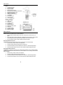
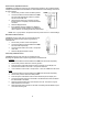
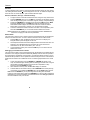
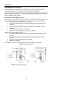
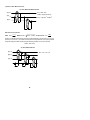
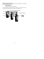
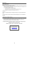
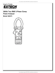
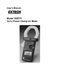
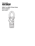
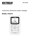
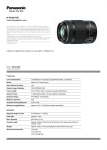
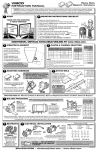
User's Manual
Clamp-on Power Datalogger
Model 382060
WARRANTY
EXTECH INSTRUMENTS CORPORATION warrants this instrument to be free of defects in parts and
workmanship for one year from date of shipment (a six month limited warranty applies on sensors and
cables). If it should become necessary to return the instrument for service during or beyond the warranty
period, contact the Customer Service Department at (781) 890-7440 for authorization. A Return
Authorization (RA) number must be issued before any product is returned to Extech. The sender is
responsible for shipping charges, freight, insurance and proper packaging to prevent damage in transit.
This warranty does not apply to defects resulting from action of the user such as misuse, improper wiring,
operation outside of specification, improper maintenance or repair, or unauthorized modification. Extech
specifically disclaims any implied warranties or merchantability or fitness for a specific purpose and will not
be liable for any direct, indirect, incidental or consequential damages. Extech's total liability is limited to
repair or replacement of the product. The warranty set forth above is inclusive and no other warranty,
whether written or oral, is expressed or implied.
Introduction
Congratulations on your purchase of the Extech 382060 True RMS Clamp-on Power
Meter. This device measures True RMS Voltage, Current, Power, Frequency,
Resistance/Continuity, and Phase Angle. The built-in datalogger stores up to 1600
readings. Optional PC software permits meter-to-PC data transfers. An optional 3-phase
adapter provides kW, kVA, or PF measurements of unbalanced loads. Careful use of
this meter will provide years of reliable service.
Safety
•
•
•
•
•
•
•
•
Read the following safety information carefully before using or servicing the meter
Do not exceed the maximum input limits published in the specifications below.
Never measure current while the test leads are inserted in the meter's input jacks.
Do not use the meter or the test leads if either appears damaged.
Use extreme caution when working near bus bars or bare conductors.
Built-in safety protection may be impaired if meter is not used per user's manual.
Use caution when working with voltages above 60VDC or 30VAC RMS.
Before resistance/continuity measurements, disconnect power/loads from the circuit.
This symbol, adjacent to another symbol or terminal, indicates the user must
refer to the manual for further information.
This symbol, adjacent to a terminal, indicates that, under normal use, hazardous
voltages may be present
Double insulation
WARNING: This indicates that a potentially hazardous condition which, if not avoided, could
result in death or serious injury.
CAUTION: This indicates that a potentially hazardous condition which, if not avoided,
could result in injury or damage to the meter.
2
2
Specifications
General Specifications
Environmental conditions
•
Installation Category III
•
Pollution degree 2
•
Altitude up to 2000 meters
•
Indoor use only
•
Relative Humidity 80% max.
•
Ambient temperature: 32 to 104 o F (0 to 40o C)
Maximum voltage
Operational design
Display
Bargraph
Over range Indication
Low battery Indication
Sampling rate
Auto power off
Power supply
Jaw size
Operating Temperature
Operating RH
Storage Temperature
Dimensions
Weight
Accessories
Optional Accessories
600Vrms
Dual slope integration
4-digit (9999 count) LCD display
40 segment display
LCD displays "OL"
Battery symbol display for low operating voltage
10 times per second (bargraph); 2 times per second (LCD)
After 30 mins. of inactivity
9V Alkaline Battery (10 hour approximate battery life)
Cable Φ46mm, 1.8”
32 to 104o F (0 to 40o C)
<80% RH non-condensing
14 to 140o F (-10 to 60o C)
10.2 x 3.7 x 1.8" (260 x 93 x 45mm)
16.6 oz. (470g) with battery (approx.)
9V battery, Test Leads, Carry Case
PC Software and Cable (382062); 3-Phase Adapter (382061)
Function Specifications
Accuracy: ± (% reading + no. of digits) at 64 to 82o F (18 to 28o C) with RH% <80%
True Power (kW)
Range*
Resolution
Accuracy
2kW to 600kW
0.1kW
± (2% + 5d)
*Minimum voltage: 100V AC, Minimum Current: 20A AC
Frequency
40 to 400Hz
Apparent Power (kVA)
Range*
Resolution
Accuracy
2kW to 600kVA
0.1kVA
± (2% + 5d)
*Minimum voltage: 100V AC, Minimum Current: 20A AC
Frequency
40 to 400Hz
Cos φ (Power Factor)
Range*
Resolution
Accuracy
Frequency Range
0.30 to 1.00
0.01
± 0.05
10Hz to 60Hz
0.00 to 0.30
Not spec.
*Minimum voltage: 100V AC, Minimum Current: 20A AC
Sensitivity
>100V / 10A
DC Current
Range
1000A
Resolution
0.1A
Accuracy
± (2% + 5d)
AC Current (True RMS)
Range
1000A
Resolution
0.1A
Accuracy
± (2% + 10d)
3
3
Frequency
40 to 400Hz
Peak Indication
Range
1000A
600V
Resolution
0.1A
0.1V
Accuracy
± (2.5% + 10d)
Acquisition time
≤ 200ms
≤ 100ms
DC Voltage
Range
600V
Resolution
100mV
Accuracy
± (0.75% + 2d)
Input Resistance
1MΩ
AC Voltage (True RMS)
Range
600V
Resolution
100mV
Accuracy
± (1.2% + 10d)
Frequency
40 to 400Hz
Input Z
1MΩ
Resistance
Range
10kΩ
Resolution
1Ω
Accuracy
± (1% + 5d)
Frequency
Range*
Resolution
1kHZ
0.1Hz
*Minimum Current: 10A AC
Accuracy
± (0.5% + 5d)
Sensitivity
10V or 10A
Overload Protection
Function
kW, kVA, PF, DCV, ACV, Peak ACV
DCA, ACA, Peak ACA
Continuity, Diode, Resistance
Frequency
Overload protection
750Vrms
1100A
660Vrms
750Vrms or 1100A
Crest Factor (ACA, ACA): 5*
* For sinusoidal waveforms. Additional errors for non-sinusoidal signals are: 1 to 3 (0.5%), 3
to 5 (3%), 5 to 7 (6%)
Audible Continuity: Audible tone sounds when resistance is less than 100Ω ±10%
4
4
Description
Meter
1. Transformer jaws
2. Jaw open trigger
3. Data Hold button
4. Range selector switch
5. DC/AC/Hz/Continuity/Diode mode button
6. MIN/MAX/AVG/PEAK button
7. Relative mode button
8. Datalogging Record button
9. LCD Display
10. PC Interface jack
11. COM input jack
12. V-Ω−Hz input jack
Display Indicators
13. Relative mode
14. Data Hold
15. Negative polarity
16. Low battery
17. Bargraph display
18. Bargraph display scale
19. Peak Hold
20. Average reading
21. Maximum reading
22. Minimum reading
Measurements
Measurement Considerations and Precautions
1. Ensure that the selected range on the meter matches the measurement to be
taken.
2. If the measured current is higher than the selected current range for long periods,
overheating may result compromising the safety of the meter's circuitry.
3. Do not measure current on high voltage conductors (>600V).
DC Voltage Measurements
WARNING: Ensure that all test leads are disconnected from the meter terminals
1. Set the rotary function switch to the V position.
2. Press the yellow DC/AC/Hz mode button to select DC.
3. Connect the black and red test leads to the COM and + terminals respectively.
4. Connect the test leads to the circuit under test and read the displayed value.
AC Voltage Measurements
WARNING: The maximum input for the AC Voltage range is 600Vrms. Do not attempt to take
voltage measurements that exceed 600Vrms. Shock hazard or meter damage could result at
higher voltages.
1. Set the rotary function switch the V position.
2. Press the yellow DC/AC/Hz button to select AC.
3. Connect the black and red test leads to the COM and + terminals respectively.
4. Connect the test leads to the circuit under test and read the displayed value.
5
5
Frequency Measurements (Voltage)
WARNING: The maximum input for the AC Voltage range is 600Vrms. Do not attempt to take
voltage measurements that exceed 600Vrms. Shock hazard or meter damage could result at
higher voltages.
1. Set the rotary function switch the V position.
2. Press the yellow DC/AC/Hz button to select Hz.
3. Connect the black & red test leads to the COM and + terminals respectively.
4. Connect the test leads to the circuit under test and read the displayed value.
Note: The voltage must be at least 10V for proper frequency measurements.
AC and DC Current Measurements
WARNING: Ensure that all test leads are
disconnected from the meter terminals
1. Set the rotary function switch to the
A position.
2. Press the yellow DC/AC/Hz mode
button to select DC or AC per the
display symbol.
3. Press the trigger to open the meter
jaws then snap them open/closed
CORRECT
INCORRECT
several times to dissipate any
residual magnetic fields. Clamp the
jaws around the conductor under test. The most accurate reading can be obtained
by keeping the conductor as near to the centering marks of the jaws as possible.
The direction of current must correspond to the indication pointer on the jaw.
4. Ensure that the jaws are completely closed around the conductor
5. Read the displayed value.
Frequency Measurements (Current)
1. Set the rotary function switch the A position
2. Press the yellow DC/AC/Hz button to select Hz per display symbol.
3. Follow the directions for AC Current measurements above.
4. The meter detects the frequency of the current for the conductor under test.
Note: For proper frequency measurements, the current through the jaw should be at
least 10A (minimum threshold).
Kilowatt (KW) and Apparent Power (KVA) Measurements
WARNING: The maximum input for the AC Voltage range is 600Vrms. Do not take voltage
measurements exceeding 600Vrms. Shock hazard and meter damage could result.
1. Set the rotary function switch the KW or KVA
position.
LOAD
2. Connect the black and red test leads to the COM
and + terminals respectively and then in parallel
with circuit under test.
3. Clamp the jaw around one conductor ensuring that
the jaws are completely enclosed around conductor.
4. Read the displayed value.
Notes:
1. The + sign printed on the jaw must face the power
source for correct readings,
2. For 3-phase unbalanced systems, use the optional 3-phase adapter (380261).
Refer to Appendix C.
6
6
Power Factor (PF) Measurements
WARNING: The maximum input for the AC Voltage range is 600Vrms. Do not attempt to take
voltage measurements that exceed 600Vrms. Shock hazard and meter damage could result
at higher voltages.
1. Set the rotary function switch the Cos ö position.
LOAD
2. Connect the black and red test leads to the COM
and + terminals respectively and then in parallel
with the circuit under test.
3. Clamp the jaw around one conductor ensuring
that the jaws are completely enclosed around the
conductor.
4. Read the displayed value.
5. If the displayed value is negative, the reading is
capacitive (current leads voltage). If the displayed
value is positive, the reading is inductive (current lags voltage).
Notes: The + sign printed on the jaw must face the power source for correct readings,
Resistance Measurements
WARNING: Remove power from the circuit under test and
discharge all capacitors before performing resistance
measurements.
1. Set the rotary function switch the Ù position.
2. Connect the black and red test leads to the COM
and + terminals respectively.
3. Connect the test leads to the circuit or component
under test.
4. Read the displayed resistance value.
Continuity and Diode Tests
WARNING: Remove power from the circuit under test and
discharge all capacitors before performing resistance measurements.
Continuity
1. Connect the black and red test leads to the COM and + terminals respectively.
2. Set the rotary function switch the continuity position.
3. Press the yellow mode select switch to select continuity per the display icon.
4. Connect the test leads to the circuit or component under test.
5.
If the resistance of the circuit or component is < 100Ω, an audible tone will sound.
Diode
1. Connect the black and red test leads to the COM and + terminals respectively.
2. Set the rotary function switch the diode position.
3. Press the yellow mode select switch to select diode test per the display icon.
4. Connect the red test lead to the anode side of the diode and the black test lead to
the cathode side of the diode.
5. Read the forward voltage value of the diode on the LCD. The value for a good
diode should be 0.3 to 0.7VDC
6. Reverse the test lead connection to the diode, the reading should indicate an open
circuit if the diode is good.
7
7
Features
Data Hold
To hold a displayed value, press the violet colored data hold button (above the rotary switch).
The reading will freeze and the H symbol will appear on the LCD. To release the display and
return the meter to normal operation, press the data hold button again.
Minimum, Maximum, Average, and Peak Readings
1. To begin a session, first select the desired function using the rotary select switch.
2. Press the MIN/MAX button once. The MIN icon will appear on the display and the
meter will begin keeping track of the lowest, highest, average, and peak readings.
3. Pressing the MIN/MAX key repeatedly scrolls through the MIN (minimum), MAX
(maximum), AVG (average), and PEAK (peak capture) readings since the
measurement session began. The meter will continue to monitor the session
keeping track of the minimum, maximum, etc. until the session is halted.
4. To exit the measurement session and return the meter to normal operation, press
and hold the MIN/MAX key for 2-3 seconds until the audible tone sounds.
Note: Peak Hold is only available for Current and Voltage functions. MIN/MAX/AVG
functions do not apply to COS and KVA parameters.
Relative Mode
This meter has to ability to store a reference value so that measurements can be displayed
relative to the reference value. To store a reference value and use the relative mode:
1. Press the REL key when the desired reference value is on the display, the
triangular relative symbol will appear on the LCD.
2. All subsequent measurements will be displayed relative to the reference value. For
example, if 100 is displayed at the time of the REL key-press and the next
measurement is 105, the LCD will read 5 (105 - 100 = 5).
3. To exit the Relative mode, press and hold the REL key for 2-3 second until the
audible tone sounds.
Datalogging and the RS-232 PC Interface
This meter has the ability to store 1600 measurements. Stored data can be transferred from
the meter to a PC using the optional PC Interface kit (382062). Data can then be exported to
and manipulated in spreadsheet, word processor, or graphical software programs. The PC
Interface kit also permits the user to operate the meter remotely from the PC. Instructions for
the RS-232 PC Interface are included with the kit. The following steps detail how to record
data
1. To start recording data, press the RECORD key (RECORD will appear on the
LCD); the meter will begin recording data one reading per second. Note: Using the
optional Data Acquisition software, the sample rate is adjustable. To stop
recording, press the RECORD key again.
2. When the meter's memory is full, the RECORD display icon will flash.
3. To delete data from the meter's memory hold the RECORD button while powering
up the meter. Do not release the RECORD button until the CLEP display appears.
Note: Press the RECORD key to stop recording before shutting down the meter.
Powering off the meter before pressing the RECORD key to stop recording prohibits the
datalogger from marking the address of the last data record. The datalogger updates the
last record address every 100 records.
8
8
Appendices
True RMS Measurement Notes
The Model 382060 is a True RMS responding device that can correctly measure nonsinusoidal waveforms such as triangle, square, and distorted sine waves.
Conventional average-sensing meters convert the measurement signal into an average value
and then multiply the average by 1.1. If the measurement signal is anything but a true sine
wave the reading will be incorrect.
Single Phase, 3-Wire Measurements
To perform this test, two separate measurements are required: WL1G and WL2G (refer to the
diagram below). Measure WL1G first (steps 1 –5). L1/L2/G must be correctly identified.
1. Set the rotary function switch to the KW range.
2. Connect the red test lead to the meter's red voltage terminal and then to the L1
conductor.
3. Connect the black test lead to the meter's COM input jack and then to the G
conductor.
4. Clamp the meter around the L1 conductor.
5. Note the WL1G reading displayed on the LCD for later use.
Measure WL2G as described in steps 6 – 9.
6. Connect the red test lead to the meter's red voltage terminal and then to the L2
conductor.
7. Connect the black test lead to the meter's COM input jack and then to the G
conductor.
8. Clamp the meter's jaws around the L2 conductor
9. Note the WL2G reading.
Now use the WL1G & WL2G readings noted above in the equation shown below:
W 1φ3W = W (L1G) + W ( L2G )
9
9
3 phase, 3-Wire Measurements
3 φ / 3 wire Balanced Measurements
W3φφ = WRS + WTS
(φ1) R
VAR3φφ = Sqr (3(W RS -WTS ))
(φ2) S
VA3φφ = Sqr (W 3φφ 2 +VAR3φφ 2)
WRS
(φ3) T
WTS
Miscellaneous formulae
V*A
KW
; KVAR: KVAR = ( KVA) 2 − (KW ) 2 ; Power Factor: PF =
1000
KVA
KVAR is a calculated value and its accuracy greatly depends on the accuracy of V, A, KW,
and PF (if it is close to 1). For better accuracy when PF is greater than 0.91 (φ<25o), measure
the phase angle and obtain KVAR using the following equation for a pure sine wave.
KVA: KVA =
KVAR = KVA * sinφ
3 φ / 4wire
4
Measurements
(φ1) R
W3φφ = W1 + W2 + W3
(φ2) S
W1
(φ3) T
W2
W3
10
10
Optional 3-Phase Adapter (382061)
Connect the adapter to the bottom of the meter (over the input terminals). Use of this adapter
permits three phase measurements of:
1.True Power (KW)
2.Apparent Power (KVA)
3.Power Factor PF (Cosine of Phase Angle)
Set the Clamp Meter's rotary switch to KW, KVA, or COS φ position depending upon which
parameter is to be measured. Refer to the diagram and equations below:
3 φ / 3wire Unbalanced Measurements
(φ1) R
W3φφ = W 1 + W2 + W3
(φ2) S
(φ3) T
VA3φφ = VA1 + VA2 + VA3
W1
PF3φφ =
W2
W3
11
11
W3φφ
VA3φφ
Maintenance
Battery Replacement
Warning: To prevent electrical shock, power down the clamp meter and disconnect the test
leads before removing the meter's back cover.
When the 9V battery voltage falls to a critical level, the battery symbol will appear on the
LCD. Replace the battery as follows:
1. Set the range switch to the OFF position.
2. Remove the 3 rear screws and remove the meter's rear cover.
3. Replace the 9V battery and reinstall the back cover.
Cleaning
Warning: To avoid electrical shock or damage to the meter, do not permit water inside the
case.
Periodically wipe the case with a damp cloth and mild detergent. Do not use abrasives or
solvents.
Calibration and Repair Services
Extech offers comple te repair and calibration services for all of the products we sell.
For periodic calibration, NIST certification or repair of any Extech product, call customer
service for details on services available. Extech recommends that calibration be
performed on an annual basis to insure calibration integrity.
Copyright © 2000 Extech Instruments Corporation. All rights reserved including the right of
reproduction in whole or in part in any form.
382060 User's Manual, Version 1.3, Revision Date: 31 August 2000
(
Tech Support Hotlines
781-890-7440 ext. 200
[email protected]
www.extech.com
12
12