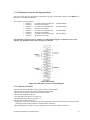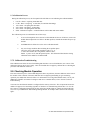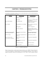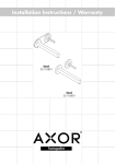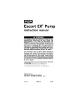
1
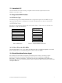
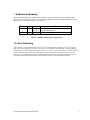
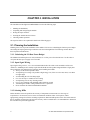
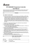
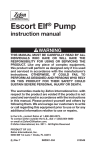
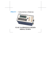
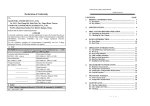
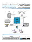
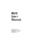
CTI 2559-RTD
EIGHT-POINT RTD MODULE
INSTALLATION AND OPERATION GUIDE
Version 1.2
CTI Part # 062-00337-012
062-00337-012
2559RTDIOG 062209
$25
Copyright © 2005 Control Technology Inc.
All rights reserved.
This manual is published by Control Technology Inc., 5734 Middlebrook Pike, Knoxville, TN
37921. This manual contains references to brand and product names that are trade names,
trademarks, and/or registered trademarks of Control Technology Inc. Siemens® and Simatic® are
registered trademarks of Siemens AG. Other references to brand and product names are trade names,
trademarks, and/or registered trademarks of their respective holders.
DOCUMENT DISCLAIMER STATEMENT
Every effort has been made to ensure the accuracy of this document; however, errors do occasionally
occur. CTI provides this document on an "as is" basis and assumes no responsibility for direct or
consequential damages resulting from the use of this document. This document is provided without
express or implied warranty of any kind, including but not limited to the warranties of
merchantability or fitness for a particular purpose. This document and the products it references are
subject to change without notice. If you have a comment or discover an error, please call us toll-free
at 1-800-537-8398.
REVISION HISTORY
Version 1.0
Version 1.1
Version 1.2
12/13/04
01/05/05
11/12/08
06/22/09
Original Release
Corrections made to Table 3.1 and Table 3.2 added.
Corrections to 2 wire connection figure caption
CTI 2559-RTD Installation and Operation Guide
iii
PREFACE
0B
This Installation and Operation Guide provides installation and operation instructions for the CTI
2559-RTD Eight-Point Resistance Temperature Detector (RTD) Input Model for SIMATIC® 505
programmable controllers. We assume you are familiar with the operation of SIMATIC® 505 series
programmable controllers. Refer to the appropriate SIMATIC® 505 user documentation for specific
information on the SIMATIC® 505 programmable controllers and I/O modules.
This Installation and Operation Guide is organized as follows:
Chapter 1 provides an overview of the module.
Chapter 2 covers installation and wiring.
Chapter 3 is a guide to troubleshooting.
The Model 2559-RTD 8-Pt RTD Module
CTI 2559-RTD Installation and Operation Guide
v
USAGE CONVENTIONS
1B
NOTE:
Notes alert the user to special features or procedures.
CAUTION:
Cautions alert the user to procedures that could damage equipment.
WARNING:
Warnings alert the user to procedures that could damage equipment and endanger the user.
CTI 2559-RTD Installation and Operation Guide
vii
TABLE OF CONTENTS
2B
PREFACE........................................................................................................................................................... V
USAGE CONVENTIONS .............................................................................................................................. VII
TABLE OF CONTENTS................................................................................................................................. IX
TABLE OF FIGURES ..................................................................................................................................... XI
CHAPTER 1. OVERVIEW ...............................................................................................................................1
1.0. Product Summary ......................................................................................................................................1
1.1. Front Panel Description .............................................................................................................................1
1.2. Asynchronous Operation ...........................................................................................................................2
1.3. Immediate I/O ............................................................................................................................................3
1.4. Supported RTD Probes ..............................................................................................................................3
1.4.1. RTD Probe Type ...........................................................................................................................3
1.4.2. RTD Ohm Values .........................................................................................................................3
1.4.3. 2-Wire, 3-Wire, 4-Wire ................................................................................................................3
1.5. Direct Resistive Device Input ....................................................................................................................3
1.6. Digital Word Map......................................................................................................................................4
1.7. RTD to Digital Conversion........................................................................................................................4
1.7.1. Engineering Unit...........................................................................................................................4
1.7.2. Scaled Integer Data .......................................................................................................................4
1.8.Module Addressing ...................................................................................................................................5
1.9. Error Reporting ..........................................................................................................................................5
CHAPTER 2. INSTALLATION .......................................................................................................................6
2.1. Planning the Installation ............................................................................................................................6
2.1.1. Calculate the I/O Base Power Budget...........................................................................................6
2.1.2. Input Signal Wiring ......................................................................................................................6
2.1.3. Selecting RTDs .............................................................................................................................7
2.1.3.1 Four-wire RTDs ...........................................................................................................7
2.1.3.2 Three-wire RTDs..........................................................................................................7
2.1.3.3 Two-wire RTDs............................................................................................................7
2.2. Unpacking the Module ..............................................................................................................................7
2.3. Configuring the Module ............................................................................................................................8
2.3.1. Selecting the Input Resistance ......................................................................................................9
2.3.2. Selecting RTD Probe Type ...........................................................................................................9
2.3.3. Selecting the WX Word Input Format ..........................................................................................9
2.3.4. Selecting Lead Resistance Compensation ..................................................................................10
2.3.5. Selecting the Error Format..........................................................................................................10
2.3.6. Selecting Digital Filtering...........................................................................................................10
2.3.7. Selecting Run or Calibration Mode ............................................................................................10
2.4. Inserting the Module into the I/O Base....................................................................................................10
2.5. Wiring the Input Connector .....................................................................................................................10
2.5.1. Connecting RTD Input Wiring ...................................................................................................11
2.5.2. Terminating the Wire Shielding .................................................................................................13
2.6. Installing the Screw Terminal Connector ................................................................................................14
CTI 2559-RTD Installation and Operation Guide
ix
2.7. Calibrating the Module ........................................................................................................................... 15
2.7.1 Calibration Requirements ............................................................................................................ 15
2.7.2. Calibration Connector Wiring Instructions ................................................................................ 15
2.7.3. Calibration Procedure................................................................................................................. 15
2.7.4. Calibration Process..................................................................................................................... 16
2.7.5. Calibration Troubleshooting ...................................................................................................... 16
2.8. Checking Module Operation ................................................................................................................... 16
CHAPTER 3. TROUBLESHOOTING .......................................................................................................... 18
HARDWARE SPECIFICATIONS ................................................................................................................. 21
APPENDIX A. COMPATIBILITY WITH SIEMENS® 505-7038 .............................................................. 23
APPENDIX B. RTD TEMPERATURE VS RESISTANCE ........................................................................ 25
LIMITED PRODUCT WARRANTY ............................................................................................................. 27
REPAIR POLICY ............................................................................................................................................ 28
x
CTI 2559-RTD Installation and Operation Guide
TABLE OF FIGURES
3B
Figure 1.1 CTI 2559-RTD Front Panel ................................................................................................. 2
Figure 1.2 Word Input to the PLC ....................................................................................................... 4
Figure 1.3 Digital Representation of Input Temperature Change ..................................................... …4
Figure 2.1 Configuration Dipswitch Location and Function ................................................................ 9
Figure 2.2 Screw Terminal Connector Wiring .................................................................................... 11
Figure 2. 3 RTD Sensor Wiring .......................................................................................................... 12
Figure 2.4 Terminating the Wire Shielding ....................................................................................... 13
Figure 2.5 Input Connector Assembly ................................................................................................ 14
Figure 2.6 Calibration Connector Wiring Diagram ............................................................................ 15
Figure 2.7 Example I/O Configuration Chart..................................................................................... 17
Figure 3.1 Troubleshooting Matrix... .................................................................................................. 18
LIST OF TABLES
4B
Table 1.1 RTD Types ........................................................................................................................... 3
Table 1.2 Supported RTD Ohm Values ................................................................................................ 3
Table 1.3 Module Addressing Configurations .................................................................................. …5
Table 2.1 Dipswitch Assignments......................................................................................................... 8
Table 2.2 Precision Resistor Values for Calibration .......................................................................... 14
Table 3.1 Problem Codes and Messages Reported for 3 Wire Mode ................................................ 19
Table 3.2 Problem Codes and Messages Reported for 4 Wire Mode ................................................ 20
CTI 2559-RTD Installation and Operation Guide
xi
CHAPTER 1. OVERVIEW
5B
1.0. Product Summary
13B
The CTI 2559-RTD Eight-Channel RTD Module is a member of Control Technology’s family of I/O modules
compatible with the SIMATIC® 505 programmable controllers. It is a single-wide module that is compatible
with two-, three-, and four-wire RTDs, with automatic lead wire resistance compensation for three-wire and
four-wire RTDs.
The 2559-RTD pulses a small amount of current through the RTD. The module measures the voltage
generated by the current through the RTD and determines the resistance. Lookup tables relating temperature to
resistance for different RTD probes are used to determine the temperature.
1.1. Front Panel Description
Active
LED
Figure 1.1 CTI 2559-RTD Front Panel
The Active LED will be illuminated when the module is functioning normally. If the Active LED is not lit, or
if it is blinking the module is not working properly. Refer to Chapter 3 for troubleshooting.
1.2. Asynchronous Operation
The module operates asynchronously with respect to the PLC (a scan of the PLC and input sampling of the
module do not occur at the same time). Instead, the module will translate all RTD inputs in one module update
(25 milliseconds maximum) and store the translated words in buffer memory. The PLC retrieves the stored
words from the module buffer memory at the start of the I/O scan.
2
CTI 2559-RTD Installation and Operation Guide
1.3. Immediate I/O
14B
The 2559-RTD has been tested and is fully compatible with the immediate input instruction for the
SIMATIC® 545 and 555 PLCs.
1.4. Supported RTD Probes
15B
1.4.1. RTD Probe Types
26B
Seven RTD probe types from standard RTD materials are supported as inputs to the 2559-RTD. The types
supported are listed in Table 1.1. RTD types are selectable with dipswitches 4, 5, and 6 on switch block 1.
1.4.2. RTD Ohm Values
27B
RTD types are supported in the following ohm values listed in Table 1.2. These values are selectable with
dipswitches 1, 2, and 3 on switch block 1.
RTD Type
Ohms (Ω) 0.0 Cº
Platinum 0.003850
Platinum 0.003916
Platinum 0.003902
Platinum 0.003920
Copper 0.004274
Nickel 0.006720
Nickel 0.006178
Table 1.1 RTD Types
100 Ω
120 Ω
130 Ω
200 Ω
500 Ω
1000 Ω
10 Ω
9.03 Ω
Table 1.2 Supported RTD Ohm Values
1.4.3. 2-Wire, 3-Wire, and 4-Wire RTDs
The 2559-RTD supports 2-wire, 3-wire, and 4-wire RTD probes that are selectable on dipswitch 1 on switch
block 2. Position 0 is for 4-wire RTDs and position 1 selects 2- and 3-wire RTDs.
1.5. Direct Resistive Device Input
16B
Direct ohm inputs to the module are supported for measuring resistive loads or with resistive sensors.
Resistance measurements are made by setting dipswitches 7 and 8 on switch block 1 to Ohms (Ω).
Dipswitches 1, 2, and 3 on switch block 1 are used to select the order of magnitude of the resistance to be
measured (10 Ω or 1k Ω). By selecting 10 Ω Ohm, values are reported as ohms x 100 to the PLC and selecting
1k Ω reports ohms x 10.
CTI 2559-RTD Installation and Operation Guide
3
1.6. Digital Word Map
17B
RTD inputs are translated into 16-bit digital words. Figure 1.2 illustrates the WX word format represented in
the PLC.
1
0
Sign
Bit
MSB
2
0
3
0
4
0
5
0
6
1
LSB
7 8 9 10 11 12 13 14 15 16
0 0 0 0 0 0 0 0 0 0
15 Bits Reporting Data
Figure 1.2 Word Input to the PLC
1.7. RTD Input to Digital Conversion
18B
1.7.1. Engineering Units
28B
Temperature can be reported in Fahrenheit or Celsius degrees times 10 as a word input.
As an example, the following Figure 1.2 illustrates the effects of a change in input level going from 0 to
102.4oF in the RTD Input Mode.
Example 1:
0.0oF = (Digital Word (WX))/10
1
0
+
MSB
2
0
.
3
0
.
Example 2:
4
0
.
5
0
.
6
0
.
7
0
.
8
0
.
9
0
.
LSB
10 11 12 13 14 15 16
0 0 0 0 0 0 0
. 32 16 8 4 2 1
102.4oF = (Digital Word (WX))/10
1
0
+
MSB
2
3
0
0
.
.
4
0
.
5
0
6 7
1 0
1024
8
0
.
9
0
.
LSB
10 11 12 13 14 15 16
0 0 0 0 0 0 0
. 32 16 8 4 2 1
Figure 1.3 Digital Representation of Input Temperature Change
1.7.2. Scaled Integer Data
29B
When the data format is selected as Integer, the full temperature range of the RTD is scaled as an unsigned
integer from 0 to 32000. The following formulas may be used to calculate the scaled integer value for
temperature.
Temperature:
4
Scaled Integer = (measured temp - min temp) / (max temp - min temp) x 32000
ex: the scaled integer offset at 0oC for a 100Ω Pt RTD is:
Scaled integer = (0 - (-199.8)) / (849 - (-199.8)) x 32000 = 6091
CTI 2559-RTD Installation and Operation Guide
1.8. Module Addressing
19B
The 2559-RTD module can be configured as an 8 WX or 16 WX word module. This is selectable using
dipswitch 2 on switch block 2. Table 1.3 lists the WX configurations for the 2559-RTD module. In 16 WX
mode, errors are reported in Words 9-16 for inputs 1-8.
Format
WX16
Inputs
8
WX8
8
I/O
Values
WX 1-8 Input Points 1-8
WX 9-16 Separate Error Words
WX 1-8 Input Points 1-8, upscale errors
Table 1.3 Module Addressing Configurations
1.9. Error Reporting
If the module is set for 8WX and an error occurs, the input data are replaced by an error word and
that input ceases updating. You must correct the error condition before the input resumes updating.
If the module is set for 16WX word inputs and an error occurs, the last valid data are frozen. An error
word is reported in one of the last eight inputs as shown in Table 3.2 This allows the error to be
detected in your application program without immediately affecting controller operation. Errors are
reported as values greater than or equal to 32752. Refer to Table 3.2 for error code descriptions.
CTI 2559-RTD Installation and Operation Guide
5
CHAPTER 2. INSTALLATION
6B
The installation of the Eight-Point RTD Module involves the following steps:
1.
2.
3.
4.
5.
Planning the installation,
Unpacking and configuring the module.
Wiring the input connector.
Inserting the module into the I/O base.
Checking module operation.
The steps listed above are explained in detail in the following pages.
2.1. Planning the Installation
20B
Planning is the first step in the installation of the module. This involves calculating the I/O base power budget
and routing the input signal wiring to minimize noise and selecting RTDs. The following sections discuss
these important considerations.
2.1.1. Calculating the I/O Base Power Budget
30B
The Model 2559-RTD requires 2.8 watt (maximum) of +5 VDC power from the I/O base. Use this value to
verify that the base power supply is not exceeded.
2.1.2. Input Signal Wiring
31B
Input signal wiring can be 2, 3 or 4-wire twisted shielded cable. The cable can be stranded or solid 14-24
AWG wire. Standard practices usually require that all shields be tied together and grounded at a single point.
These guidelines will minimize noise problems when installing the module.
• Always use the shortest possible cables
• Avoid placing low voltage wire parallel to high-energy wire (if the two wires must meet, cross them
at a right angle)
• Avoid bending the wire into sharp angles
• Use wire raceways or conduit for wire routing
• Avoid placing wires on any vibrating surface
• Use a 4-wire conductor with shielding and tie shield to ground.
• Terminating the shield to earth ground at the PLC is preferred.
• Never terminate the shield at both the RTD and PLC.
2.1.3 Selecting RTDs
32B
RTDs should be selected to optimize the accuracy of temperature measurements over the range of
temperatures to be measured, survive in the environmental conditions where it will operate, and be
appropriately packaged to meet the mounting requirements. Platinum RTD probes are the most stable material
that is commonly used and provide long-term accuracy. Refer to manufacturer’s recommendation to determine
the best RTD for a particular application.
6
CTI 2559-RTD Installation and Operation Guide
2.1.3.1 Four-wire RTDs
Four-wire RTDs give the best accuracy and are not affected by changes in terminal, wire, or contact
impedance. Wire type and temperature coefficients do not affect accuracy, and wire impedance is relatively
unimportant for the Sense+ and Sense- wires.
2.1.3.2 Three-wire RTDs
3B
Three-wire RTDs are less accurate than the 4-wire RTDs. The contact resistances cannot be compensated for
and could become significant. The following guidelines will minimize errors.
o Minimize the difference in resistance between the Source and Return
o Resistive differences cause offsets.
o Wire the Sensor as illustrated in Figure 2.3
o Restrict the lead resistance to less than 50Ω.
o Source and Return wires should have same temperature coefficient.
2.1.3.3 Two-wire RTDs
34B
Two-wire RTDs can be used if accuracy is non-critical. Lead resistance and lead-wire temperature drift cause
temperature offsets .
2.2. Unpacking the Module
Open the shipping carton and remove the special anti-static bag which contains the module. After discharging
any static build-up, remove the module from the static bag. Do not discard the static bag. Always use this bag
for protection against static damage when the module is not inserted into the I/O backplane.
CAUTION:
HANDLING STATIC SENSITIVE DEVICES
The components on the Model 2559-RTD module printed circuit card can be damaged by static
electricity discharge. To prevent this damage, the module is shipped in a special anti-static bag.
Static control precautions should be followed when removing the module from the bag, when
opening the module, and when handling the printed circuit card during configuration.
CTI 2559-RTD Installation and Operation Guide
7
2.3 Configuring the Module
The 2559-RTD is configured using two switch blocks located at the top front of the module. Table
2.1 lists the features and options associated with the dipswitches and the default configuration of the
module.
NOTE:
Configuration applies to ALL CHANNELS.
NOTE: Shipping Configuration
100Ω Pt 0.003850 °F × 10 3-Wire 16WX 60Hz Digital Filtering
Table 2.1 Dipswitch Assignments
Feature
Options
Assembly
Switches
Default
Input
resistance
at 0°C
One of eight values
for input resistance
at 0°C. Also selects
the reporting scale
for direct Ω input.
S1
1, 2, and 3
Probe type
One of 7 RTD curves.
S1
4, 5, and 6
WX input
Format
°F × 10
°C × 10
ohms x 10
ohms x 100
scaled integer.
S1
7 and 8
°F × 10
Lead resistance
Compensation
2-, 3-, or 4-wire.
S2
1
3-wire
Error format
16WX/separate error
words or
8WX/upscale errors
(32752 and above).
S2
2
16WX
Input filtering
50 or 60 Hz.
S2
3
60 Hz
Digital filtering
Enable/Disable
S2
4
Enabled
Calibration
Run or calibration
mode.
S2
8
Run
100 Ω
Pt 0.003850
DIN
Figure 2.1 shows the location of the two switch-blocks on the module with a detailed diagram illustrating the
location and function of the dipswitches used to configure the module.
8
CTI 2559-RTD Installation and Operation Guide
Figure 2.1 Dipswitch Locations and Function
2.3.1 Selecting the Input Resistance.
Dipswitches 1, 2, and 3 are used to select RTD resistance for the probe types. When measuring ohm (Ω)
values, select 1k Ω, which reports ohms x 10, or 10 Ω, when measuring resistive values less than 100 Ω.
These values are reported as ohms x 100. Refer to Figure 2.1.
2.3.2. Selecting RTD Probe Type.
Seven RTD material types are selectable using dipswitches 4, 5, and 6 on switch block 1. Refer to Figure 2.1.
2.3.3. Selecting WX Word Input Format.
Dipswitches 7 and 8 on switch block 1 are used to select the format that data is presented in the WX input
word for the 8 channels. Refer to Section 1.7.1 for engineering format and Section 1.7.2 for scaled integer
format. Reporting ohm Ω resistive values is also selected using dipswitches 7 and 8 on switch block 1. Data is
presented as ohms x 10 or 100, °F x 10, °C x 10, or as a scaled integer.
CTI 2559-RTD Installation and Operation Guide
9
2.3.4. Selecting Lead Resistance Compensation.
Dipswitch 1 on switch block 2 is used to select the type of lead compensation. Two- and three-wire
compensation is selected with a 1 and 4-wire with a 0.
2.3.5. Selecting the Error Formatting.
Dipswitch 2 on switch block 2 is used to select how errors are reported. With the dipswitch in the 1 position
the module logs into the base as a WX16 module. Errors are reported in words WX 9-16. In the zero position
the module logs into the base as a WX8 module. When errors occur, error words are written to the
corresponding data word and the error condition must be cleared before data is again reported.
2.3.6. Selecting Digital Filtering.
Digital Filtering is selected by positioning dipswitch 4 on switch block 2 in the 1 position. Selecting digital
filtering will limit data fluctuations due to signal noise.
2.3.7. Selecting Run or Calibration Mode.
Dipswitch 8 on switch-block two is in the 1 position for normal operation. To calibrate the module, put
dipswitch 8 in the 0 position.
2.4. Inserting the Module into the I/O Base
21B
Avoid installing the 2559-RTD in a slot adjacent to a high-energy switching module.
WARNING:
Turn power off to base before installing or removing the module.
Insert the module into the I/O base by carefully pushing the module into the slot. When the module is fully
seated in the slot and backplane connector, tighten the captive screws at the top and bottom to hold the module
in place. To remove the module from the I/O base, loosen the captive screws then remove the module from the
I/O base. Be careful not to damage the edge card at the back of the module when inserting or removing the
module.
2.5. Wiring the Input Connectors
2B
Input signals are accepted through a standard 40 terminal connector located on the front of the module. Figure
2.2 illustrates how the wiring is connected to the front connector via recessed screw terminals. The screw
terminals can accept wire sizes up to single stranded 14-gauge wire. The actual size used depends on the RTD
wire providing the input signal.
To assign an input to a specific channel, locate the appropriate channel position on the screw terminal
connector as shown in the Figure 2.4 and connect wiring.
10
CTI 2559-RTD Installation and Operation Guide
Figure 2.2 Screw Terminal Connector Wiring
2.5.1. Connecting RTD Input Wiring
35B
For RTD input circuits, connect the RTD wires to the screw terminals on the front connector. Refer to Figure
2.2 and Figure 2.3 to determine the correct channel and proper wiring connections for 2-wire, 3-wire, and 4wire RTDs. After the wires are inserted in the correct terminals, tighten the screws using CARE not to overtighten and strip the connector terminal. Repeat this procedure for the remaining RTD input channels.
CTI 2559-RTD Installation and Operation Guide
11
Two-wire, no lead compensation
Set module to 2/3 wire mode
Figure 2.3 RTD Sensor Wiring
12
CTI 2559-RTD Installation and Operation Guide
2.5.2. Terminating the Wire Shielding
36B
Conductor shielding must be connected to earth ground. Terminating the shield to earth ground at the PLC is
preferred. If terminating the shield at the PLC, follow procedures illustrated in Figure 2.4. NEVER terminate
the shield at both the RTD and PLC.
Figure 2.4 Terminating the Wire Shielding
CTI 2559-RTD Installation and Operation Guide
13
2.6. Installing the Screw Terminal Connector
23B
When all the input signal wires are connected to the screw terminal connector, carefully install the connector
on the front of the module (see Figure 2.5).
Figure 2.5 Input Connector Assembly
2.7. Calibrating the Module
24B
The 2559-RTD is calibrated at the factory and needs no calibration when installed. The module should be
calibrated yearly for best accuracy. If the module operates in an environment where the ambient temperature
cycles outside the range of 20 o C to 30o C, more frequent calibration may be required. Also, if the ambient
temperature is constantly outside the range of 20 o C to 30o C, calibration at the ambient temperature may
improve accuracy.
NOTE:
The 2559-RTD Input Module is calibrated at the factory for initial installation. Further calibration
may be required depending on the environment in which the module and/or the RTD operates..
2.7.1 Calibration Requirements
37B
Calibration of the 2559-RTD is accomplished by the use of a standard 505 connector (CTI P/N 4-565) and
four precision resistors. Make sure the resistors meet or exceed the specifications in Table 2.2.
Table 2.2 Precision Resistor Values for Calibration
Ohms
20.00
402.0
2000.0
4020.0
14
Tolerance
0.001%
0.001%
0.001%
0.001%
Temperature Coefficient
25 ppm/oC
10 ppm/oC
10 ppm/oC
10 ppm/oC
CTI 2559-RTD Installation and Operation Guide
2.7.2 Calibration Connector Wiring Instructions
Precision resistor values for calibration are installed on a specially wired 40-Pin connector which MUST be in
place prior to initiating the calibration.
The connector is wired as follows:
o Channel 1
o Channel 2
o Channel 3
o Channel 4
o Channel 5
o Channel 6
o Channel 7
o Channel 8
Four Wire 2000.0 Ohm Resistor
Short all four terminals
Four Wire 402.0 Ohm Resistor
Short all four terminals
Four Wire 20.00 Ohm Resistor
Short all four terminals
Four Wire 4020.0 Ohm Resistor
Short all four terminals.
(500 Ohm Range)
(100 Ohm Range)
(10 Ohm Range)
(1K Ohm Range)
The calibration connector wiring for channels 1-4 is illustrated in Figure 2.6. Channels 5-8 are wired
similarly, just substitute resistor values from the preceding list.
Figure 2.6 Calibration Connector Wiring Diagram
2.7.3 Calibration Procedure
38B
The following steps are needed to ensure proper calibration of the module:
1. Remove power from the 505 rack that contains the RTD module.
2. Remove the field wiring connector from the RTD module.
3. Remove the module from the rack.
4. Set dipswitch 8 SW2 to the Cal (0) position.
5. Install the precision resistors per Figure 2.6.
6. Reinsert the module into the rack.
7. Apply power to the rack. The module LED will begin to blink slowly and, after around 3 minutes, the LED
will begin to blink rapidly to indicate completion of the calibration.
8. Work through the above steps in a backward progression to return the module to operation.
CTI 2559-RTD Installation and Operation Guide
15
2.7.4 Calibration Process
39B
During the calibration process, the front panel LED will blink at a rate indicating the Calibration Phase.
1.
2.
3.
4.
5.
6.
0.25 Hz - Phase 1 Acquiring 2000 Ohm data
0.5 Hz - Phase 2 Acquiring 0 Ohm data (for 200/500 Ohm Range)
1 Hz - Phase 3 Acquiring 402 Ohm data
2 Hz - Phase 4 Acquiring 20 Ohm data
4 Hz - Phase 5 Acquiring 4020 Ohm data
Solid - Calibration complete - set Run/Calibrate switch to Run and restart module.
The calibration process is terminated in one of three ways.
1.
A successful completion leaves the Active LED SOLID ON. Power off the base, remove the
module. Return dipswitch 8 on SW 2 to the Run position, reinstall the module and power up
the base.
2.
An EEPROM write failure leaves the Active LED SOLID OFF.
3.
Any out of range condition detected during the acquisition phase
causes the Active LED to blink out Morse Code S - O - S,
i.e. three short flashes, three long flashes, and three short
flashes. A pause occurs, then the pattern repeats. The calibration failed but the existing
calibration in the module is UNAFFECTED.
2.7.5. Calibration Troubleshooting
40B
If the LED does not follow the slow-fast blinking that describes a successful calibration, one or more of the
calibration resistors may be out of range. Call CTI if module does not properly calibrate after re-checking the
procedure and calibration connector.
2.8. Checking Module Operation
25B
First turn on the base power. If the module diagnostics detect no problems, the status indicator on the front of
the module will be solid red. If the status indicator does not light, begins blinking (or goes out during
operation), the module has detected a failure. For information on viewing failed module status, refer to your
SIMATIC® TISOFT user manual. To diagnose and correct a module failure, refer to the next section on
troubleshooting.
You must also check that the module is configured in the memory of the PLC. This is important because the
module will appear to be functioning regardless of whether it is communicating with the PLC. To view the
PLC memory configuration chart listing all slots on the base and the inputs or outputs associated with each
slot, refer to your SIMATIC® TISOFT Programming Manual. An example chart is shown in the following
figure.
16
CTI 2559-RTD Installation and Operation Guide
I/O Module Definition for Channel…….1 Base..…..00
Number of Bit and Word I/O
I/O Address
Slot
1
2
.
.
15
16
0001
0000
.
.
0000
0000
X
00
00
.
.
00
00
Y
00
00
.
.
00
00
WX
08
00
.
.
00
00
WY
00
00
.
.
00
00
Special
Function
NO
NO
.
.
NO
NO
Figure 2.7 Example I/O Configuration Chart
In this example, the 2559-RTD module is inserted in slot 1 in I/O base 0 and configured as a WX8 word
module. Data for channel 1 appears in word location WX1, data for channel 2 appears in word location WX2,
etc. For your particular module, look in the chart for the number corresponding to the slot occupied by the
module. If word memory locations appear on this line, then the module is registered in the PLC memory and
the module is ready for operation.
If the line is blank or erroneous, re-check the module to ensure that it is firmly seated in the slots. Generate the
PLC memory configuration chart again. If the line is still incorrect, contact your local distributor or CTI at 1800-537-8398 for further assistance.
NOTE:
Refer to Hewlett-Packard Applications Note 290 or Omega Temperature Handbook, Volume 26,
Section T, for “practical RTD measurement” applications.
CAUTION:
For proper operation, ensure that the 2559-RTD and the RTD wires are not subjected to drafts or
large temperature gradients during operation.
NOTE:
In the event the 2559-RTD detects an onboard module failure, the module will assert the module fail
line and report the module failure in the I/O Status Word, which is reported to the PLC. CTI strongly
recommends the user application monitor the I/O Module Status Words which are Status Words 1126 and apply to SIMATIC® Controllers TI/545, TI/555, TI/560 & 565, and the TI/575. The I/O
Module Status Word can be used to report a module failure for an I/O Module in any of the 505 I/O
slots. Please refer to Siemens® SIMATIC® 505 Programming Reference Manual for more
information. If a module failure is reported by the status word, the module should be replaced with a
working unit and the failed module sent in for repair.
CTI 2559-RTD Installation and Operation Guide
17
CHAPTER 3. TROUBLESHOOTING
7B
If the module provides improper readings or the Active LED status indicator is not on, use the following chart
to determine the appropriate corrective action.
Symptom
Active LED is not lit.
U
Probable Cause
Base or PLC power is off.
Corrective Action
Turn base or PLC on.
Module has failed.
Return to CTI for repair.
Blown fuse.
Measure F1 for continuity. Return
to CTI if Blown
Return to CTI for calibration or
recalibrate per manual.
U
U
Active LED is blinking.
No calibration data.
Incorrect inputs.
Wrong addresses for word input.
Check program for correct word
input addresses.
Not logged in.
Read I/O configuration.
Incorrectly calibrated.
Return the module to CTI for
calibration or recalibrate according
to instructions.
Input does not work with PID
loop or analog alarm block.
Value is not reported as integer
0-32,000.
Select INTEGER format with
dipswitches 7 and 8 on SW1.
Value is too large.
Temperature is reported to PLC as
value x10.
Divide value by 10 in PLC.
Incorrect values to PLC.
(values off by 10-15 degrees)
DIP switch not set in correct
position.
Verify position of dipswitches.
Wrong RTD type selected by
dipswitches.
Verify position of dipswitches.
Unbalanced lead wires
Check lead resistance.
Signal wire noise
Refer to Section 2.1.2
Figure 3.1 Troubleshooting Matrix
When it is inconvenient to visually check the status indicator, use the TISOFT “Display Failed I/O”
or “Show PLC Diagnostics” support functions. If after consulting the chart above, you are unable to
diagnose the problem, contact your local distributor or CTI at 1-800-537-8398 for further assistance.
18
CTI 2559-RTD Installation and Operation Guide
Table 3.1 Problem Codes and Messages Reported in Three Wire Mode
Signed
Integer
32767
Hex
Code
7FFF
32766
7FFE
Input underrange
RTD input is below expected range
32765
7FFD
Input overrange
RTD input is above expected range
32764
7FFC
Not Used
32763
7FFB
Sense short
32762
7FFA
Input not wired
32761
32760
32759
7FF9
7FF8
7FF7
32758
7FF6
32757
32756
32755
32754
7FF5
7FF4
7FF3
7FF2
32753
7FF1
32752
7FF0
Source open
Not used
Not used
Source-to-Return
overrange
Not used
Not used
Not used
Not used
Invalid RTD Type
selected
Not used
3
0003
Problem
Description
Corrective Action
Not used
Three/Two-wire
mode
CTI 2559-RTD Installation and Operation Guide
Short from Sense+ to Return (3-wire)
Check dipswitches.
Check wiring, sensor.
Check dipswitches.
Check wiring, sensor.
Check wiring, sensor.
All three inputs are open or improperly
wired: Source, Sense+, and SenseSource to Return ≥ 20K Ω
Check Source wire.
>20K Ω from Source to Return
Check wiring, sensor.
Invalid selection of RTD material,
TCR, and Ω combination
Select Valid RTD Type
Module is correctly performing 3/2wire conversions for this input
(separate error words only)
Module channel
functioning properly
Wire module channel.
19
Table 3.2 Problem Codes and Messages Reported in Four Wire Mode
Signed
Integer
32767
Hex
Code
7FFF
32766
7FFE
Input underrange
RTD input is below expected range
32765
7FFD
Input overrange
RTD input is above expected range
32764
7FFC
Not used
32763
7FFB
Sense short
32762
7FFA
Input not wired
32761
32760
32759
7FF9
7FF8
7FF7
32758
7FF6
32757
32756
32755
32754
7FF5
7FF4
7FF3
7FF2
32753
7FF1
32752
7FF0
Source open
Not used
Sense - open
Source-to-Return
overrange
Not used
Not used
Not used
Not used
Invalid RTD Type
selected
Not used
4
0004
Four-wire mode
20
Problem
Description
Corrective Action
Not used
Short from Sense+ to Return (3-wire) or
from Sense+ to Sense- (4-wire)
All three inputs are open or improperly
wired: Source, Sense+, and SenseSource to Return ≥ 20K Ω
Check dipswitches.
Check wiring, sensor.
Check dipswitches.
Check wiring, sensor.
Check wiring, sensor.
Wire module channel.
Check Source wire.
Check Sense - wire.
>20K Ω from Source to Return
Check wiring, sensor.
Invalid selection of RTD material,
TCR, and Ω combination
Select Valid RTD Type
Module is correctly performing 4-wire
conversions for this input (separate
error words only)
Module channel
functioning properly
CTI 2559-RTD Installation and Operation Guide
HARDWARE SPECIFICATIONS
8B
Input Channels:
8 RTD inputs
RTD Types:
Platinum 0.003850
Platinum 0.003916
Platinum 0.003902
Platinum 0.003920
Copper 0.004274
Nickel 0.006720
Nickel 0.006178
European DIN Standard
American Curve
European DIN Standard
Supported Ohm values:
Ohms (Ω) 0.0 Cº
100 Ω
120 Ω
130 Ω
200 Ω
500 Ω
1000 Ω
10 Ω
9.03 Ω
Supported Probes Types:
2, 3, & 4 wires
RTD Excitation Current:
250 micro Amp
Lead Compensation:
1000Ω per lead wire (max)
Input Overrange Protection:
30 VDC or VAC continuous
Measurement Ranges:
10Ω Cu: -100oC to 260oC (-148oF to 500oF)
100Ω Pt: -200oC to 850oC (-328oF to 1562oF)
120Ω Pt: -80oC to 260oC (-112oF to 500oF)
ADC Resolution:
16 bits
Data Presentation:
Measurement returned in 0.1 degree resolution as
temperature x10 or as an integer (0-32000). Data word
includes sign bit and 15-Bit data
CTI 2559-RTD Installation and Operation Guide
21
Measurement Units:
o
C, oF, or Ohm (selectable by module)
Digital Filtering Time Constant:
1000 ms with digital filtering enabled
Update Time:
25 ms no filtering (all channels)
Repeatability:
+/- 0.1oC, +/-0.2oF for all RTD types
Accuracy:
100Ω Pt: 0.9oC (1.6oF) from 0-60oC
Ω x 100 0.36 Ω from 0-60oC
Common Mode Rejection:
>130 dB @ 60 Hz
Normal Mode Rejection
at line frequency +/- 0.01 Hz:
at line frequency +/- 3 Hz:
>80 dB
>25 dB
Step response time: 100 Ω Pt
25 ms
Step response time: Inputs to 2 kΩ
25 ms
Connector:
Removable
Wire Gauge:
14-22 AWG
Backplane Power:
+5 VDC 2.8 Watt (maximum)
-5 VDC 0.0 Watt
Module size:
Single-wide
Isolation:
1500V channel-to-backplane
Operating Temperature:
0o to 60 o C (32o to 140o F)
Storage Temperature:
-40o to 85o C (-40o to 185o F)
Relative Humidity:
5% to 95% non-condensing
Agency Approvals Pending:
UL, ULC, FM Class 1-Div.2
Shipping Weight:
1.5 lbs. (0.68 Kg)
- Specifications subject to change without notice -
22
CTI 2559-RTD Installation and Operation Guide
APPENDIX A. COMPATIBILITY WITH SIEMENS® 505-7038
9B
Overview
The CTI 2559-RTD RTD Module was designed to be a drop-in replacement for the Siemens®
Model 505-7038. Set up of the module, wiring and PLC reporting are compatible with the 505-7038.
Digital filtering has been added as a user selectable option with dipswitch 4 on switch-block 2.
Using the CTI 2559-RTD in a 505-7038 application
The CTI 2559-RTD should fulfill all the following requirements for the 505-7038 replacement, as
outlined below:
Module setup
The CTI 2559-RTD sets up the same as its Siemen’s® counterpart. Refer to Chapter 2 for details.
Wiring
The wiring of the input connector is the same for both modules.
PLC Reporting
The word format is the same for each module. See Chapter 1 for a more detailed explanation on PLC
reporting.
CTI 2559-RTD Installation and Operation Guide
23
APPENDIX B. RTD TEMP VS. RESISTANCE
10B
.
Table C-2 120-ohm Nickel
Table C-1 Platinum 0.003850 DIN
°F
-328
-148
32
212
392
572
752
932
1112
1292
1472
1562
°C
-200
-100
0
100
200
300
400
500
600
700
800
850
100 Ω
18.49
60.25
100.00
138.50
175.84
212.02
247.04
280.90
313.59
345.13
375.51
390.26
200 Ω
36.99
120.51
200.00
277.00
351.68
424.04
494.08
561.79
627.19
690.26
751.02
780.53
500 Ω
92.47
301.27
500.00
692.50
879.20
1060.09
1235.19
1404.48
1567.97
1725.66
1877.55
1951.31
°F
-112
-58
32
122
212
302
392
482
527
°C
-80
-50
0
50
100
150
200
250
275
0.00672
66.60
86.16
120.00
157.75
200.64
248.95
303.45
366.53
401.69
DIN
0.006178
72.59
89.11
120.00
154.93
194.14
238.39
288.95
347.57
380.60
Table C-3 10-ohm Copper 0.004274
°F
-328
-238
-148
-58
32
122
212
302
392
482
°C
-200
-150
-100
-50
0
50
100
150
200
250
Ohms
1.17
3.44
5.68
7.86
10.00
12.14
14.27
16.41
18.57
20.73
CTI 2559-RTD Installation and Operation Guide
25
LIMITED PRODUCT WARRANTY
1B
CTI warrants that this CTI Industrial Product shall be free from defects in material and workmanship
for a period of one (1) year after purchase from CTI or from an authorized CTI Industrial Distributor.
This CTI Industrial Product will be newly manufactured from new and/or serviceable used parts
which are equal to new in the Product.
Should this CTI Industrial Product fail to be free from defects in material and workmanship at any
time during this (1) year warranty period, CTI will repair or replace (at its option) parts or Products
found to be defective and shipped prepaid by the customer to a designated CTI service location along
with proof of purchase date and associated serial number. Repair parts and replacement Product
furnished under this warranty will be on an exchange basis and will be either reconditioned or new.
All exchanged parts or Products become the property of CTI. Should any Product or part returned to
CTI hereunder be found by CTI to be without defect, CTI will return such Product or part to the
customer.
This warranty does not include repair of damage to a part or Product resulting from: failure to
provide a suitable environment as specified in applicable Product specifications, or damage caused
by an accident, disaster, acts of God, neglect, abuse, misuse, transportation, alterations, attachments,
accessories, supplies, non-CTI parts, non-CTI repairs or activities, or to any damage whose
proximate cause was utilities or utility like services, or faulty installation or maintenance done by
someone other than CTI.
Control Technology Inc. reserves the right to make changes to the Product in order to improve
reliability, function, or design in the pursuit of providing the best possible Product. CTI assumes no
responsibility for indirect or consequential damages resulting from the use or application of this
equipment.
THE WARRANTY SET FORTH ABOVE IN THIS ARTICLE IS THE ONLY WARRANTY CTI
GRANTS AND IT IS IN LIEU OF ANY OTHER IMPLIED OR EXPRESSED GUARANTY OR
WARRANTY ON CTI PRODUCTS, INCLUDING WITHOUT LIMITATION, ANY WARRANTY
OF MERCHANTABILITY OR OF FITNESS FOR A PARTICULAR PURPOSE AND IS IN LIEU
OF ALL OBLIGATIONS OR LIABILITY OF CTI FOR DAMAGES IN CONNECTION WITH
LOSS, DELIVERY, USE OR PERFORMANCE OF CTI PRODUCTS OR INTERRUPTION OF
BUSINESS, LOSS OF USE, REVENUE OR PROFIT. IN NO EVENT WILL CTI BE LIABLE
FOR SPECIAL, INCIDENTAL, OR CONSEQUENTIAL DAMAGES.
SOME STATES DO NOT ALLOW THE EXCLUSION OR LIMITATION OF INCIDENTAL OR
CONSEQUENTIAL DAMAGES FOR CONSUMER PRODUCTS, SO THE ABOVE
LIMITATIONS OR EXCLUSIONS MAY NOT APPLY TO YOU.
THIS WARRANTY GIVES YOU SPECIFIC LEGAL RIGHTS, AND YOU MAY ALSO HAVE
OTHER RIGHTS WHICH MAY VARY FROM STATE TO STATE.
Chart used with permission from Omega Engineering, Inc.
CTI 2559-RTD Installation and Operation Guide
27
REPAIR POLICY
12B
In the event that the Product should fail during or after the warranty period, a Return Material
Authorization (RMA) number can be requested orally or in writing from CTI main offices. Whether
this equipment is in or out of warranty, a Purchase Order number provided to CTI when requesting
the RMA number will aid in expediting the repair process. The RMA number that is issued and your
Purchase Order number should be referenced on the returning equipment's shipping documentation.
Additionally, if the product is under warranty, proof of purchase date and serial number must
accompany the returned equipment. The current repair and/or exchange rates can be obtained by
contacting CTI's main office at 1-800-537-8398.
When returning any module to CTI, follow proper static control precautions. Keep the module away
from polyethylene products, polystyrene products and all other static producing materials. Packing
the module in its original conductive bag is the preferred way to control static problems during
shipment. Failure to observe static control precautions may void the warranty. For additional
information on static control precautions, contact CTI's office at 1-800-537-8398.
28
CTI 2559-RTD Installation and Operation Guide