1
Stand alone Multi- channel
Digital Video Recorder
User Instruction Manual
VERSION 1.1
Before attempting to connect or operate this product, please read these instructions carefully and
save this manual for future use.
Warning
¾
This apparatus must be earthed.
¾
Apparatus shall be connected to a mains socket outlet with a protective earthing connection.
¾
The mains plug or an appliance coupler shall remain readily operable.
¾
To prevent fire or electric shock hazard, do not expose this apparatus to rain or moisture.
¾
The apparatus should not be exposed to dripping or splashing and that no objects filled with liquids, such as
vases, should be placed on the apparatus.
¾
All work related to the installation of this product should be made by qualified service personnel or system
installers.
¾
The connections should comply with local electrical code.
The lightning flash with arrowhead symbol, within an equilateral triangle, is intended to
alert the user to the presence of uninsulated “dangerous voltage” within the product’s
enclosure that may be of sufficient magnitude to constitute a risk of electric shock to
persons.
The exclamation point within an equilateral triangle is intended to alert the user to the
presence of important operating and maintenance (servicing) instructions in the
literature accompanying the appliance.
Important Notice: (for U.S. fileds only)
This product contains a CR Coin Cell Lithuim Battery which contains Perchlorate Material – special handling
may apply.
1
Limitation of liability
This publication is provided “as is” without warranty of any kind, either express or implied, including but not
limited to, the implied warranties of merchantability, fitness for any particular purpose, or non-infringement of the
third party’s right.
This publication could include technical inaccuracies or typographical errors. Changes are added to the
information herein, at any time, for the improvements of this publication and/or the corresponding product(s).
Disclaimer of warranty
In no event shall our company be liable to any party or any person, except for replacement or reasonable
maintenance of the product, for the cases, including but not limited to below:
(1) Any damage and loss, including without limitation, direct or indirect, special, consequential or exemplary,
arising out of or relating to the product;
(2) Personal injury or any damage caused by inappropriate use or negligent operation of the user;
(3) Unauthorized disassemble, repair or modification of the product by the user;
(4) Any problem, consequential inconvenience, or loss or damage, arising out of the system combined by the
devices of third party.
(5) Any claim or action for damages, brought by any person or organization begin a photogenic subject, due to
violation of privacy with the result of that surveillance-camera’s picture, including saved data, for some reason,
becomes public or is used for the purpose other than surveillance.
2
INSTALLATION & SAFEGUARDS
Please read these instructions before operating the unit.
Installation.
Refer all work related to the installation of this product to qualified service personnel or system installers.
Avoid the following locations for installation.
* Places exposed to direct water, moisture, or sunlight directly
* Places subject to having strong vibration or impact
* Near magnetic field sources such as a television or speakers, magnet, etc.
* Steamy and oily places such as kitchens
* Places which are not level
* Place where condensation forms easily, where temperature changes greatly.
* Place the DVR in a well-ventilated place and do not place heat-generating objects on the unit.
Built-in hard disk drive
Hard disk drive is vulnerable to vibration. Handle it with care.
Performance and lifetime of hard disk drive is easily affected by heat (used at high temperature)
characteristically. It is recommended to use this unit at temperatures between 20℃-30℃{68℉-86℉}.
It is possible to damage it if it is moved while it motor is still running. Do not move it just after turning it
power on or off (for around 30 seconds).
A lifetime of hard disk drive is limited by use.
It is recommended to replace it after around 18000 hours of operation to prevent data loss from disk failures.
Write error may occur frequently after around 20000 hours of operation and the head and motor deterioration
may occur and will reach their lifetime after 30000 hours of operation when it has been used at the
recommended ambient temperature (approx. 25℃{77℉}).
When hard disk drive trouble occurs, replace it immediately. Consult your dealer for servicing.
When replacing the hard disk drives, take notice of the following.
z
Protect the hard disk drives from static electricity.
z
Do not keep them upright.
z
Do not use an electric screwdriver to fix them.
3
(Tightening torque: Approx. 0.49 N. m {5 Kgf.cm})
z
Avoid rapid changes of the temperature/humidity to prevent condensation.
(Acceptable change: within 15℃/h{59℉/h})
Before You Start.
1. Do not attempt to open or remove the covers. This may expose you to dangerous voltage or other hazards.
2. Installation should be performed by a qualified service person only.
3. This unit should be operated only from the type of power source indicated on the manufacturer’s label.
Special Note.
If you need to change the TIME/DATE always clear the Hard Drive. If you don’t follow this step first, it may
cause erratic behaviour of the DVR and possible loss of recordings.
1. It is recommended to use the same manufacturer when installing Hard Drives.
2. When backing up data, if there is any other data in USB disk, please save it, otherwise the original
documents will be deleted when video records backup.
Note:
If DVR is accessed through router, all of the protocol TCP and UDP should be opened in router setup. It can
avoid video loss phenomenon when remote access.
4
Important safety instructions
z
Read and keep these instructions.
z
Heed all warning.
z
Do not connect this unit to an outlet to which appliances with high power consumption such as an air
conditioning or a copy machine is already being connected.
z
Do not use this apparatus near water.
z
To reduce the risk of electric shock, do not remove cover (or back).
z
Clean only with dry cloth.
z
Do not block any ventilation openings. Install in accordance with the manufacturer’s instructions.
z
Do not install near any heat sources such as radiators, heat registers, stoves, or other apparatus (including
amplifiers) that produce heat.
z
Do not defeat the safety purpose of the polarized or grounding-type plug. A polarized plug has two blades
with one wider than the other. A grounding type plug has two blades and a third grounding prong. The wide
blade or the third prong are provided for your safety. If the provided plug does not fit into your outlet, consult
an electrician for replacement of the obsolete outlet.
z
Protect the power cord from being walked on or pinched particularly at plugs, convenience receptacles, and
the point where they exit from the apparatus.
z
Only use attachments/accessories specified by the manufacturer.
z
Use only with the cart, stand, tripod, bracket, or table specified by the manufacturer, or sold with the
apparatus. When a cart is used, use caution when moving the cart/apparatus combination to avoid injury from
tip-over.
z
Unplug this apparatus during lightning storms or when unused for long periods of time.
Refer all servicing to qualified service personnel. Servicing is required when the apparatus has been damaged
in any way, such as power-supply cord or plug is damaged, liquid has been spilled or objects have fallen into
the apparatus, the apparatus has been exposed to rain or moisture, does not operate normally, or has been
dropped.
5
Content
Chapter I
Introduction......................................................................................................................................... 9
Chapter II System Installation ............................................................................................................................ 11
Section 1 Operating Environment............................................................................................................... 11
Section 2 HDD Installation......................................................................................................................... 11
Section 3 Back panel .................................................................................................................................. 14
Back panel of typeⅠ 4 channel model (page.6)..................................................................................... 14
Back panel of type Ⅱ model (page.6) ................................................................................................... 15
Back panel of typeⅠ 16 channel model (page.6)................................................................................... 16
Back panel of type Ⅲ model (page.6) ................................................................................................... 18
Section 4 External alarm in/out connection ................................................................................................ 19
Alarm in................................................................................................................................................... 19
Alarm out................................................................................................................................................. 19
Section 5
PTZ (pan, tilt and zoom) control connection .............................................................................. 20
Section 6 Intercom........................................................................................................................................ 21
Section 7 A/D capture input............................................................................................................................. 22
ChapterⅢ DVR Operation ................................................................................................................................... 23
Section 1 DVR Front Panel ........................................................................................................................ 23
TypeⅠ 4 channel model and type Ⅱ model (page.6) .......................................................................... 23
TypeⅠ 16 channel model (page.6)......................................................................................................... 24
Type Ⅲ model (without LCD) (page.6) ................................................................................................ 26
Type Ⅲ model (with LCD) (page.6)...................................................................................................... 27
Section 2
IR remote device (optional) ........................................................................................................ 28
Section 3 Mouse operation ......................................................................................................................... 30
Section 4
Input mode introduction.............................................................................................................. 31
Chapter IV System operation.............................................................................................................................. 33
Section 1 Menu Navigation .......................................................................................................................... 33
Section 2 Surveillance View ......................................................................................................................... 34
Status Bar................................................................................................................................................. 34
Screen Switch .......................................................................................................................................... 35
Screen Circular Monitor .......................................................................................................................... 36
Section 3 Login and Logout ......................................................................................................................... 36
System Login ........................................................................................................................................... 36
System Logout ......................................................................................................................................... 37
Section 4 System Reboot .............................................................................................................................. 37
Shutdown ................................................................................................................................................. 37
Reboot...................................................................................................................................................... 37
Section 5 OSD Setup .................................................................................................................................... 38
Time Modify ............................................................................................................................................ 38
Time Display............................................................................................................................................ 39
Channel Name Setup and Display ........................................................................................................... 39
Section 6 Basic Parameter Setup .................................................................................................................. 40
Section 7 HDD Management........................................................................................................................ 41
HDD State Inquiry ................................................................................................................................... 41
6
Recording Auto Overwrite....................................................................................................................... 42
Section 8 Recording...................................................................................................................................... 42
Record Parameter Setup .......................................................................................................................... 42
Manual Recording ................................................................................................................................... 44
Schedule Recording ................................................................................................................................. 44
Recording Alarm Setup............................................................................................................................ 46
Alarm Elimination ................................................................................................................................... 49
Section 9 Playback/Backup .......................................................................................................................... 49
Playback................................................................................................................................................... 49
Backup ..................................................................................................................................................... 51
Section 10 Network Setup ............................................................................................................................ 52
Static/DHCP ............................................................................................................................................ 52
PPPoE ...................................................................................................................................................... 53
DDNS setup ............................................................................................................................................. 53
Section 11 Net Transfer Parameter Setup ..................................................................................................... 54
Section 12 User Management ....................................................................................................................... 55
Add User.................................................................................................................................................. 56
Setup the password for new user ............................................................................................................. 56
Rights Setup............................................................................................................................................. 57
Delete user ............................................................................................................................................... 58
Section 13 Display Setup.............................................................................................................................. 58
Section 14 PTZ Setup ................................................................................................................................... 59
Serial Port ................................................................................................................................................ 60
PTZ Control............................................................................................................................................. 62
Section 15 Restore Defaults Setting ............................................................................................................. 63
Section 16 Information Inquiry..................................................................................................................... 64
Log Information....................................................................................................................................... 64
Version Information ................................................................................................................................. 64
User Information...................................................................................................................................... 65
Section 17 System Update ............................................................................................................................ 65
Section 18 Reset ........................................................................................................................................... 66
ChapterⅤ IE Monitor............................................................................................................................................. 67
Section 1 Introduction...................................................................................................................................... 67
Section 2 Installation Requirements ................................................................................................................ 67
Section 3 Network Connection Operation ....................................................................................................... 67
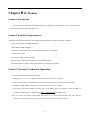
Section 4 Basic Surveillance Operation........................................................................................................... 68
Start Program ........................................................................................................................................... 68
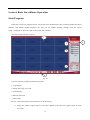
Login/logout ............................................................................................................................................ 69
Switch the image view scale.................................................................................................................... 69
Video Display Area Operation................................................................................................................. 69
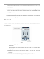
PTZ Control............................................................................................................................................. 70
Shortcut Operation Button ....................................................................................................................... 71
Section 5 Menu Configuration Setup............................................................................................................... 72
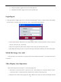
Recording And Playback ......................................................................................................................... 72
Info search ............................................................................................................................................... 73
7
Rec.&Alarm............................................................................................................................................. 73
Local Setup .............................................................................................................................................. 74
Advance Setup ......................................................................................................................................... 74
Remote control ........................................................................................................................................ 76
Chapter Ⅵ Frequency Asked Questions.............................................................................................................. 77
Appendix 1 HDD Capability Calculate .............................................................................................................. 78
8
Chapter I
Introduction
Thank you for choosing our stand alone Digital Video Recorder System.
Please pay attention to these instructions before using the DVR.
The manual explains the operation modes and performance criteria of our stand alone H264 DVR.
Please read the manual carefully before using the DVR, and install the system according to the instructions.
Mainframe software is subject to renewal without prior notice.
TypeⅠ
4/16 channel model for synchronize video and audio
TypeⅡ
4/8 video channel and 1 audio channel input model
TypeⅢ
ATM special model
9
Product Introduction
1. Compress
¾
Support PAL/NTSC video format, 25FPS (PAL), 30 FPS (NTSC), H.264; Support both variable bitrate
and variable frame rate.
¾
Support dual stream, video config setting.
¾
Support motion detection, video shelter area.
¾
Support OSD, date and time display.
2. Record
¾
Support record period, record quality setting; Support pre-record function.
¾
Support SATA port.
¾
TypeⅠ 4 channel model and type Ⅲ model Support 4CH playback synchronously for CIF resolution;
TypeⅠ 16 channel model and type Ⅱ 8 channel model support 1CH playback for CIF resolution.
¾
Support FAT32 files system.
¾
Support backup the recorded files. Support USB memory, USB HDD.
¾
Support cycle or none cycle record.
3. Control
¾
Support exception alarm, motion detection alarm, external alarm, etc.
¾
Support user authority setting, the authority distribute to each channel respectively.
4. Network
¾
Support TCP/IP protocol, DHCP, PPPoE, DDNS.
¾
Support E-Mail.
¾
Support embedded WEB preview and IE browse.
¾
Support remote parameters setup.
¾
Support network port control, realize PC remote operate.
¾
Alarm information can be sent to remote center.
¾
Network control PTZ.
¾
Network download and playback the recorded files in DVR.
¾
Remote upgrade the firmware.
¾
Support log.
10
¾
Set username, password and authority remotely.
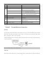
Chapter II
Section 1
System Installation
Operating Environment
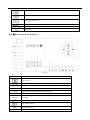
The following operating environment for this DVR must be adhered to:
DVR Operating Environment
Items
Instructions
Electromagnetism
DVR’ complies with National Electromagnetism
Radiation Standards.
Temperature
-10℃ to 55℃
Humidity
10 % to 95 %
Power Supply
12V volts D.C. input
Please pay particular attention to the following:
¾
Keep away from heat sources and high temperatures and avoid direct sunlight.
¾
Do not leave in humid places and never touch with wet hands.
¾
Never spill liquids of any kind on the unit.
¾
The unit is only to be opened by qualified persons.
¾
Do not place other equipment on the DVR.
Section 2
HDD Installation
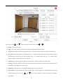
Installation of Hard Drive.
1. Remove DVR Lid.
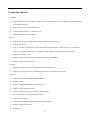
TypeⅠ 4 channel model and type Ⅱ model(page.6) should be removed as fig.1.
11
Fig. 1
TypeⅠ 16 channel model and type Ⅲ model(page.6) should be removed as fig.2.
Fig. 2
2. Remove HDD mounting bracket.
3. Fit HDD onto bracket using supplied mounting screws.
4. Replace HDD mounting bracket.
5. Connect the ATX power cable to the power connection on the HDD. Pay attention to the correct
orientation.
6. Plug HDD cable into SATA port on HDD.
7. Plug HDD cable into SATA port on the main board.
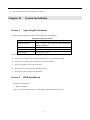
After installed, typeⅠ 4 channel model and type Ⅱ model(page.6) should be as fig.3:
12
Fig. 3
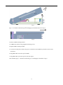
After installed, type Ⅲ model(page.6) should be as fig.4:
Fig. 4
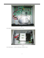
After installed, typeⅠ 16 channel model (page.6) should be as fig.5:
13
Fig. 5
8. Replace the top of the DVR enclosure. Note: Please fix the screws at the back side of
DVR before the flank side while assembling the lid.
NOTE: Please format the hard disk before record.
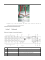
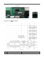
Section 3
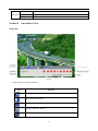
Back panel
Back panel of typeⅠ 4 channel model (page.6)
Fig. 6
No.
Interface
Connection Description
1
(A IN) Audio input
connect simulate audio input device, standard BNC interface
2
(V IN)Video input
connect simulate video input device, standard BNC interface
(A OUT)Audio output
connect audio output device, standard BNC interface
Active device is requested while exporting audio
4
(V OUT) Video output
connect monitor, local video signal output
5
RS485 port
connect RS485 device, details refer to “Section 5
3
14
PTZ (pan, tilt and
zoom) control connection”
Alarm input
connect alarm input device(4CH,details refer to “Section 4
alarm in/out connection”)
External
Alarm output
connect alarm output device (1CH , details refer to “Section 4
External alarm in/out connection”)
6
VGA interface
connect VGA display device, such as PC VGA display
7
RJ45 interface(UTP)
connect network
8
USB interface
connect USB device. Up-side link is USB2.0 which adapt to USB
storage device. Down-side link is USB1.1 which adapt to USB mouse.
9
intercom output
audio output while connecting with DVR_WEB, this port will occupy
the signal from “A OUT”, they are alternatively taken.
10
intercom input
audio input while connecting with DVR_WEB, this port will occupy
the signal from “A IN 1”, they are alternatively taken.
11
power supply(DC 12V)
12V volts D.C. input
Note: 1. Active device is requested while using intercom function and output audio.
2. For this model, the audio output ports are the same ports for the intercom.
Back panel of type Ⅱ model (page.6)
Fig. 7
No.
Interface
1-2 (V IN)Video input
Connection Description
connect simulate video input device, standard BNC interface
3
(A IN) Audio input
connect simulate audio input device, standard BNC interface
4
(V OUT) Video output
connect monitor, local video signal output
RS485 port
connect RS485 device, details refer to “Section 5
zoom) control connection”
Alarm input
connect alarm input device(4CH,details refer to “Section 4
alarm in/out connection”)
Alarm output
connect alarm output device (1CH , details refer to “Section 4
External alarm in/out connection”)
5-1
5-2 4 CH alarm input
PTZ (pan, tilt and
connect alarm input device(4CH,details refer to “Section 4
alarm in/out connection”)
15
External
External
6
VGA interface
connect VGA display device, such as PC VGA display
7
RJ45 interface(UTP)
connect network
8
USB interface
connect USB device. Up-side link is USB2.0 which adapt to USB
storage device. Down-side link is USB1.1 which adapt to USB mouse.
9
intercom output
audio output while connecting with DVR_WEB
10
intercom input
audio input while connecting with DVR_WEB
11
power supply(DC 12V)
12V volts D.C. input
Note:
Active device is requested while using intercom function and output audio.
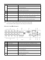
Back panel of typeⅠ 16 channel model (page.6)
Fig. 8
Number
Function
Description
1
Power Supply Input(AC IN)
110/220V AC Voltage Input
2
Video Input(V IN)
Connect analog video input device, standard BNC port
3
Normal editions are for audio input Normal edition DVR connect to audio input device, standard BNC
connector.
Loop editions are for video loop Loop out edition DVR connect to video matrix and monitor,
output (AIN/V OUT)
standard BNC connector.
4
Video Output ( SPOT VOUT and Local video signal output
VOUT)
Reserved(AOUT2)
N/A
Audio output (AOUT1)
Connect the audio output device, standard RCA port
6
RS-232 port
System Debug port
7
VGA Port
Connect VGA displays
8
Network port(UTP)
Connect the network
9
USB Port
5
10
Connect USB mouse, data backup, The two USB ports are
alternative.
RS485 port
connect RS485 device, details refer to “Section 5
and zoom) control connection”
Alarm input (ALARM IN)
connect alarm input device(16CH,details refer to “Section 4
External alarm in/out connection”)
16
PTZ (pan, tilt
Alarm output(ALARM OUT)
connect alarm output device (4CH,details refer to “Section 4
External alarm in/out connection”)
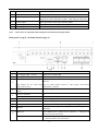
Remark 1
RS-485 and alarm input port defines as follow fig:
Fig. 9
¾
T+, T- are senders of RS485, connect to Rx+ and Rx- of PTZ or dome. Details refer to “Section 5
PTZ (pan, tilt and zoom) control connection”.
Note: RS485(2) is set as default,If you want to use 485(1) port for PTZ control, please setup as
following:
“Menu--Network--Serial Port Setup—PTZ Port:Port1”.
¾
R+, R- are receivers of RS485, connect to keyboard. This DVR can only use 485(1) port for keyboard.
Remark 2 RS485 matched resistance
Open the cover, there is a 2*4 pin header (SW1) between Network port and RS485 port. They can control 120Ω
resistance for RS485(2).
Pin
1
2
3
4
Function
N/A
Control 120Ω resistance for RS485(2)
N/A
17
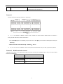
Back panel of type Ⅲ model (page.6)
Fig. 10
No.
1
Interface
A/D capture input (optional)
Connection Description
Alarm read analogue input, and it can connect sensor
18
2
Video Input (V IN)
BNC input
3
Audio Input (A IN)
BNC input
4
power supply(DC 12V/5A)
12V volts D.C. input
RS485 port
connect RS485 device, details refer to “Section 5
(pan, tilt and zoom) control connection”
Alarm input (ALARM IN)
connect alarm input device(8CH,details refer to “Section
4
External alarm in/out connection”)
Alarm output(ALARM OUT)
connect alarm output device (2CH , details refer to
“Section 4 External alarm in/out connection”)
6
VGA interface
connect VGA display device, such as PC VGA display
7
RS-232 connector
Connect RS-232 device, modem and PC for example
8
RJ45 connector (UTP)
Network port
9
USB interface
connect USB device. Up-side link is USB2.0 which adapt
to USB storage device. Down-side link is USB1.1 which
adapt to USB mouse.
10
Video Output(V OUT)
Connect monitor, local video output
11
Audio Output(AOUT)
connect audio output device, standard BNC interface
5
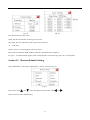
Section 4
PTZ
External alarm in/out connection
Alarm in
The alarm input is NO/NC input. Please connect signal port to any of 1-16 port and GND port. For NO input
please setup “Main Menu—Rec. &Alarm—Alarm—Open” in the menu. For NC input please setup “Main
Menu—Rec. &Alarm—Alarm—Open” in the menu.
4 CH series DVR has 4 ports for alarm input, 8 CH series DVR has 8 ports for alarm input, 16 CH series DVR has
16 ports for alarm input.
Fig. 11
Note: external input voltage can not be higher than 5V.
Alarm out
Alarm output is NO/NC output. TypeⅠ 4 channel model and type Ⅱ model (page.6) has 1 CH alarm output, type
19
Ⅲ model (page.6) provides 2 CH alarm output, and TypeⅠ 16 channel model (page.6) has 4 CH alarm output.
When “NO1” and “COM1” was off, the alarm output disables, otherwise “NO1” and “COM1” was connected,
the alarm output enable.
TypeⅠ 4 channel model and type Ⅱ model (page.6) alarm output linkage should be as follows:
Fig. 12
TypeⅠ 16 channel model and type Ⅲ model (page.6) alarm output linkage should be as follows:
Fig. 13
Note: 24V DC (1A), 120V AC (1A) voltage and current are suggested.
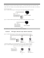
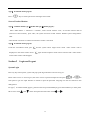
Section 5
PTZ (pan, tilt and zoom) control connection
TypeⅠ 4 channel model and type Ⅱ models’ (page.6) PTZ linkage should be as follows:
Fig. 14
A and B ends of RS485 can be connected with the Rx+, Rx- on PTZ or High Speed Dome.
TypeⅠ 16 channel model and type Ⅲ models’ (page.6) PTZ linkage should be as follows:
20
Fig. 15
T+ and T- ends of RS485 can be connected with the Rx+, Rx- on PTZ or High Speed Dome.
After all the above connection, please enter the “PTZ” menu to setup camera and PTZ address, baud rate, PTZ
protocol.
After the setup, click “
” icon on the status bar to enter the PTZ control interface. Also you can run the
DVR_WEB software or Netclient to control PTZ. About the DVR_WEB setting please refer “Chapter Ⅴ”.
Note: TypeⅠ 16 channel model (page.6) support 485(1)and 485(2) port, RS485(2) is set as default,
If you want to use 485(1) port for PTZ control, please setup as following:
“Menu--Network--Serial Port Setup—PTZ Port:Port1”.
WARNING: PLEASE SET ALL OF THE PTZ ADDRESSES DIFFERENTLY.
Note:
Please do not connect RS485 and RS232 simultaneously.
Section 6
Intercom
Fig. 16
In the above illustration, the up icon is an ear phone socket and the down icon is a MIC phone socket. After the
DVR_WEB or Netclient software has connected with the host, and also the ear phone and MIC phone be
connected. Click the intercom icon on the DVR_WEB, a two-way communication can be realized. In the
meantime, audio input from DVR can be heard on PC; audio input from PC can be heard on audio output of DVR.
About the DVR_WEB setting please refer “ChapterⅤ”.
NOTE: 1. TypeⅠ 16 channel model and type Ⅱ model’s (page.6) intercom is independent.
2. TypeⅠ 4 channel model and type Ⅲ model’s (page.6) intercom input will take up the channel 1
audio input, intercom output is audio output port
3. Active device is requested while using intercom function for typeⅠ 4 channel model and type
Ⅲ model (page.6). Other type model can not use active device while using intercom function.
21
Section 7 A/D capture input
Fig. 17
This function is optional function for type Ⅲ model (page.6).
It provides 4 analog input ports and special for type Ⅲ model (page.6). The ports can be connected with sensor for
temperature or humidity.
22
ChapterⅢ
Section 1
DVR Operation
DVR Front Panel
TypeⅠ 4 channel model and type Ⅱ model (page.6)
Fig. 18
Name
specification
Power switch
IR receiver
Run
Working indicator, flashing after boot normally.
HDD
HDD indicator, flashing when access HDD date.
ACTIVE
Network communication indicator, flashing when network is connected.
LINK
Network connection indicator, lighting constantly when network is
connected.
REMOTE
IR remote receive indicator, flashing when control this DVR with IR
controller.
ALARM
Record indicator
Backup
Alarm indicator, flashing when alarm is activated.
Corresponding channel record indicator (it lights when corresponding
channel is recording)
Backup indicator, lighting constantly when backup is working.
1. Direction key “UP”
2. Display the status bar in preview mode
1. Direction key “DOWN”
2. Hide the status bar in preview mode
Direction key “LEFT”
Direction key “RIGHT”
ENTER
“OK” key
ESC
“Cancel” key
Menu
Entry system menu
1. For 8 CH series DVR, Select 1-split, 4-split,9-split display; for 4 CH
series DVR, select 1 split, 4 split display
23
2. Motion and Shelter area enable
3. Select pane “1” in cover area setting
1. For 8 CH series DVR, Select 1-split, 4-split,9-split display; for 4 CH
series DVR, select 1 split, 4 split display
2. Motion and Shelter area disable
3. Select pane “2” in cover area setting
1. For 8 CH series DVR, Select 1-split, 4-split,9-split display; for 4 CH
series DVR, select 1 split, 4 split display
2. Select pane “3” in cover area setting
1. For 8 CH series DVR, Select 1-split, 4-split,9-split display; for 4 CH
series DVR, select 1 split, 4 split display
2. Select pane “4” in cover area setting
Entry the backup menu
●
Pop-up the dialogue box of manual recording
1. Entry search and playback interface
2. Pause/Play recording file , under playback mode
Stop playback
Jump backward under playback mode.
Jump forward under playback mode.
Entry input interface
TypeⅠ 16 channel model (page.6)
Fig. 19
Name
specification
Power switch
POWER
Power indicator, lighting constantly when connected power
RUN
Working indicator, flashing after boot normally
HDD
HDD indicator, flashing when access HDD date
LINK
Network link indicator, lighting constantly when network is connected
ACTIVE
Network communication indicator, flashing when network is connected
Fn
PTZ control indicator, lighting constantly in PTZ mode
+10
Plus 10 indicator, it lights when +10 function is enabled
24
ALARM
1—16
Alarm indicator, flashing when alarm is activated
1-16ch record indicator(it lights when corresponding channel is recording)
1. Direction key ‘UP’;
2. Display the status column in preview mode
1. Direction key ‘DOWN’
2. Hide the status column in preview mode
Direction key ‘LEFT’;
Direction key ‘RIGHT’;
ENTER
ESC
Menu
0
“OK” key
“Cancel” key
Entering system menu mode
1. Number key “0”
2. input number “0” in input mode window
1
1. Number key ‘1’ (Corresponds relevant letter);
2. Select pane “1” in cover area
setting
3. input number “1” in input mode window
2
1. Number key ‘2’ (Corresponds relevant letter);
2. Select pane “2” in cover area
setting
3. input number “2” in input mode window
3
1. Number key ‘3’ (Corresponds relevant letter);
2. Select pane “3” in cover area
setting
3. input number “3” in input mode window
4
1. Number key ‘4’ (Corresponds relevant letter);
2. Select pane “4” in cover area
setting
3. input number “4” in input mode window
5—9
1. Number key ‘5-9’(Corresponds relevant letter)
mode window
+10
Plus 10
2. input number “5-9” in input
Channel auto-switching (sequencing)
1. Entry “Handle Record” interface; 2. Light control in PTZ mode;
input method in input mode interface
3. Switch the
1. Playback by frames under PAUSE mode
2. Wiper control in PTZ mode;
3. Select the character in input mode window
1. Jump forward
2. Focus+ In PTZ mode
1. Jump backward
2. Focus- In PTZ mode
1. Jump to next recorded file.
2. Zoom+ In PTZ mode
1. Jump to previous recorded file.
2. Zoom- In PTZ mode
1. Stop playback operation
2. Aperture+ In PTZ mode;
character in input mode window,
1. Pause playback
2. Aperture- In PTZ mode
Entry input interface
Entry “Playback Dialog” interface
Call PTZ initial position of current channel
PTZ enable switch
Cancel alarm beep
25
3.Delete current
Entry “Playback Dialog” interface
Split screen mode switch
Reserved for future use
USB port (support USB2.0 which adapt to USB storage device)
MIC and earphone
IR receiver
Type Ⅲ model (without LCD) (page.6)
Fig. 20
Name
specification
Power switch
IR receiver
POWER
Power indicator, lighting constantly when connected power
HDD
HDD indicator, flashing when access HDD date
ALARM
Alarm indicator, flashing when alarm is activated
RUN
Working indicator, flashing after boot normally
1-4CH record Corresponding channel record indicator (it lights when corresponding channel
indicator
is recording)
Entry search and playback interface
Entry input interface
Menu
Entry system menu
PTZ
Entry PTZ control mode
26
Select 1, 4 split display
1. Direction key “UP”
2. Display the status bar in preview mode
1. Direction key “DOWN”
2. Hide the status bar in preview mode
Direction key “LEFT”
Direction key “RIGHT”
ENTER
ESC
“OK” key
“Cancel” key
0
1. Number key “0”
1
1. Number key ‘1’ (Corresponds relevant letter);
2. Motion and Shelter
area enable
3. Select pane “1” in cover area setting
4. input
number “1” in input mode window
2
1. Number key ‘2’ (Corresponds relevant letter);
2. Motion and Shelter
area disable
3. Select pane “2” in cover area setting
4. input number
“2” in input mode window
3
1. Number key ‘3’ (Corresponds relevant letter);
2. Select pane “3” in
cover area setting
3. input number “3” in input mode window
4
1. Number key ‘4’ (Corresponds relevant letter);
2. Select pane “4” in
cover area setting
3. input number “4” in input mode window
5-9
2. input number “0” in input mode window
1. Number key ‘5-9’(Corresponds relevant letter)
input mode window
Type Ⅲ model (with LCD) (page.6)
Fig. 21
27
2. input number “5-9” in
Name
specification
Power switch
IR receiver
POWER
RUN
Power indicator, lighting constantly when connected power
Working indicator, flashing after boot normally
ALARM
Alarm indicator, flashing when alarm is activated
HDD
HDD indicator, flashing when access HDD date
1-4CH record Corresponding channel record indicator (it lights when corresponding channel
indicator
is recording)
Entry playback and backup interface
Entry input interface
Menu
ENTER
ESC
Entry system menu
“OK” key
“Cancel” key
1. Direction key “UP”
2. Display the status bar in preview mode
1. Direction key “DOWN”
2. Hide the status bar in preview mode
Direction key “LEFT”
Direction key “RIGHT”
1. 4-screen display or channel 1 full screen
2. Motion and Shelter area
enable 3. Select pane “1” in cover area setting
1. 4-screen display or channel 2 full screen
2. Motion and Shelter area
disable
3. Select pane “2” in cover area setting
1. 4-screen display or channel 3 full screen
area setting
2. Select pane “3” in cover
1. 4-screen display or channel 4 full screen
area setting
2. Select pane “4” in cover
1. Entry playback and backup interface
under playback mode
Stop playback
Jump backward under playback mode.
Jump forward under playback mode.
●
LCD
Section 2
Entry the “Manual Record” interface
LCD display ON/OFF
IR remote device (optional)
This is the optional part for this DVR.
28
2. Pause/Play recording file,
Insert the battery, then aim the launch end at the receive end of DVR while using IR remote controller.
In the control range, if more than one DVR need to be controlled separately, please press “ID” or “SELECT”
button, then input the host address of which DVR need to be controlled and press “OK” or “ENTER” button will
realize the function.
NOTE: Press “ID” in IR remote controller, then input “000” in “Remote Control Address Set” will control all
DVRs in the effective range.
The defaulted host address is 001, the value field among 001-255. It can be modified in the “Main
Menu-Advanced -General”.
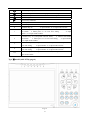
IR remote device for typeⅠ 4 channel model, type Ⅱ model and type Ⅲ model (page.6) as follows:
Fig. 22
Refer to the section of “DVR Front Panel” for the detailed description of the function of the keys on remote
controller.
: Screen-split mode switch.
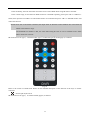
IR remote device for typeⅠ 16 channel model (page.6) as follows:
29
Refer to the section of ‘Panel’ for the detailed description of the keys function on remote control unit.
Here are the function buttons on the remote control:
Buttons
P/Z
PTZ enable switch;
SETUP
Plus 10
SAVE
Entering “Search dialog”
RETURN
Section 3
Functions
Enter the input mode window
Mouse operation
This DVR supports a USB mouse:
Plug the USB mouse into the USB port marked
, and then the mouse cursor will appear on the screen.
Note: TypeⅠ 16 channel model and type Ⅲ model (page.6), plug the USB mouse into either of the USB
ports.
¾ User Login
Right click on screen and a pop-up login box will appear; Move cursor to the password input frame,
double-click left key of mouse to enter the input box, click relevant character to input the password, then
click ENTER or right click to reserve and exit.
¾ Entry Menu
Method 1: Right click to enter the main menu after logining system.
Method 2: Move cursor to the bottom of screen, reveal the status bar automatically, and click
30
icon
to enter the main menu.
¾ Mouse Option
*Modify Number
Double-click mouse left key to input number or use trolley of mouse to modify
number directly.
*Modify Character
Double-click mouse left key to input character.
*Modify Option
Choose option with trolley of mouse or in the option box after left click.
*Exit Menu
Right click to exit menu step by step.
¾ Adjusting the Monitor views
*Image Switch
On display, move mouse cursor to bottom, status bar will reveal automatically,
then click
*Full Screen Image
icon to switch image.
when multi-screen display, move mouse cursor to a channel, double-click
mouse left key to view Full screen, double-click again will back full screen to
multi-screen.
Section 4
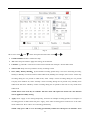
Input mode introduction
Input mode interface of typeⅠ 4 channel model, type Ⅱ model, and type Ⅲ model (page.6):
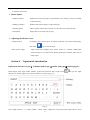
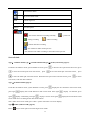
DVR support three input modes: number, capital and lowercase letter input. Press
to get into input
interface on number input box or character edit box as shown in Fig. 23:
Fig. 23
In the input interface, “←” means “delete”, “Shift” means “uppercase or lowercase letter input switch”. Press
31
“ESC” in the front panel to save and exit.
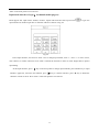
Input mode interface of typeⅠ 16 channel model (page.6):
DVR support four input modes: number, Chinese, capital and lowercase letter input. Press
to get into
input interface on number input box or character edit box as shown in Fig. 24:
Fig. 24
In the input interface, use mouse to click “123” to change input modes, click “←” and “→” to move cursor,
click “Select” to confirm selection; click “Clear” to delete the character in front of cursor. Right click to quit the
input dialog.
In the input interface, press “ ” key on the front panel to change input methods, press number key to input
numbers, uppercase, lowercase and Chinese, press “ ” key to confirm selection, press “■” key to delete the
character in front of cursor. Press “ESC” in the front panel to save and exit.
32
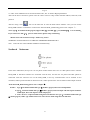
Chapter IV
System operation
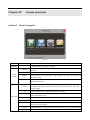
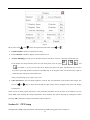
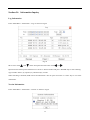
Section 1 Menu Navigation
Fig. 25
Main Menu
Sub Menu
Playback
Rec. &
Alarm
Search recording, playback or backup
General
Setup recording resolution, codec type, image quality, stream bit, frame rate of
channels
Schedule
Schedule recording channel selection and recording time period setup
Alarm
Alarm input, motion detection, video shelter and video lost alarm and
recording setup.
HDD
HDD status check, HDD format, HDD alarm and HDD overwrite
automatically setup
General
User
Display
Advanced
Function
PTZ
DVR name, remote control number, system time, menu alpha, VGA
resolution, auto logout, circular monitor, NTP, time format setup, and video
format display
Add and delete user, modify password, set user rights
Channel name modification and display, system time display, cover area setup,
video parameters setup
Communication parameters, PTZ address, PTZ protocol setup
Network
IP address, host port, DHCP, PPPoE and DDNS network parameters setup
Transfer
Set network transmission resolution, codec type, stream bit, frame rate, image
quality for every channel
Serial Port
set parameters for serial port, select the PTZ control port, temp and hum setup
Maintenance
Resume default configuration, log out, restart and timing restart.
33
Log
Information
Section 2
System running and alarm information
Version
System firmware version information and MAC
Online
Check online user information, force kick online user
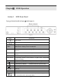
Surveillance View
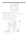
Status Bar
Fig. 26
Status bar button function definition:
Icon
Function
Entering main menu
Split screen mode switch
Entering “Manual Record” dialog
Entering “Playback” dialog
Mute mode and cancel mute mode.
34
Cancel buzzer alarm
Entry PTZ control mode
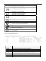
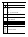
Admin
Current login user
CH01
Current channel
Notation
Icon description
Record status and remote preview switch automatically.
/
---the current channel is recording manually
---timing recording
--- prerecord
---alarm recording
---motion detection recording
---the channel is under remote preview
×---the channel is not under recording or not under remote preview.
Screen Switch
TypeⅠ 4 channel model, type Ⅱ 4 channel model and type Ⅲ model (with LCD) (page.6):
Under the surveillance mode, system defaults 4-screen, press
to have the second split screen full screen, press
to have the first split screen full screen, press
to have the third split screen full screen, press
to have the forth split screen full screen. When the first split screen is the full screen, press
to return
to 4-screen, so do the other 3 buttons.
Type Ⅱ 8 channel model (page.6):
Under the surveillance mode, system defaults 9-screen, press
press again
again
, display the first channel in full screen mode,
, display the second channel in full screen mode. Press again
, display 5-8channel, press again
, display 9-screen. Press again
, display 1-4 channels, press
, display the first channel in full
screen mode. So as to analogize the other three buttons.
Note: under non 9-screen mode, press “ESC” system will return to 9-screen display.
Type Ⅲ model (without LCD) (page.6):
Press “
” key to switch split screen and single screen mode.
35
TypeⅠ 16 channel model (page.6):
Press “
” key to switch split screen and single screen mode.
Screen Circular Monitor
TypeⅠ 4 channel model, type Ⅱ model and type Ⅲ model (page.6):
Enter “Main Menu → Advanced → General”, select circular monitor “ON”, set circular monitor interval
(interval of circle monitor), press “OK”, the system will start circular monitor. Default system configuration:
OFF.
“Auto Switch” will show on status bar when auto circular is activated.
TypeⅠ 16 channel model (page.6):
Under the surveillance mode, press
displayed on the status column. Press
and the system enters single screen mode. “Auto switch” will be
again and the sequence mode will be canceled. The “Auto switch”
on the status column will disappear.
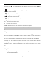
Section 3 Login and Logout
System Login
Press any key of front panel, system will pop-up the login interface as shown in Fig. 27.
Please select a user in “User Login”, then move cursor to password input box and press
or
on
front panel to get into input interface in which to input the password. Language can also be selected in this
dialogue box.
For typeⅠ 16 channel model (page.6), password can be input immediately by press the number key in front panel.
Move cursor with
and
on the front panel and select item with
36
and
.
Fig. 27
In User Login box, language, including Chinese and English.
NOTE: 1. System will activate buzzer automatically after incorrect password input.
2. System will reject login after three times incorrect password input.
3. System default administrator “Admin”, password “123456”, has the superlative level authority.
4. Assure system security, please enter ‘Main Menu-Advanced-User’ to modify original password of
Administrator in time.
System Logout
Method 1: Enter “Main Menu-Advanced-Maintenance” then select ‘Logout’ to logout the system.
Method 2: Set ‘Auto Logout’ as ON in “Main Menu”→ “Advanced”→ “General” and input idle time, then system
will auto-lock keyboard if no command input within the time set.
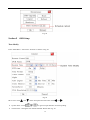
Section 4 System Reboot
Shutdown
Method 1: Press
on front panel then the shutdown interface will pop-up. DVR will be Shutdown after
inputting the username and the password correctly.
Method 2: Enter “Main Menu-Advanced-Maintenance” and select ‘Shutdown’ to shutdown DVR.
Note: After power off, restart after 10 seconds to protect disk.
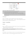
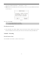
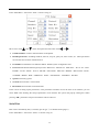
Reboot
Enter “Main Menu-Advanced-Maintenance” and select ‘reboot’ to reboot DVR manually. Please refer Fig. 28.
Schedule reboot is available, if it is selected and inputted schedule reboot time (24H) for everyday.
37
Fig. 28
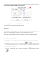
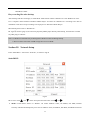
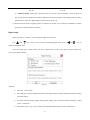
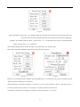
Section 5 OSD Setup
Time Modify
Enter “Main Menu-Advanced-General” as shown in Fig. 29.
Fig. 29
Move cursor with
and
on the front panel and select item with
¾
System Time:Press
¾
Time Format:Setting the time format and DST. Please refer Fig. 30.
or
and
.
to get into input interface for time inputting.
38
Note: If you need to modify system time please close the record.
Fig. 30
¾
¾
¾
Time Format: 12H and 24H is selectable
Data Format: yyyy-mm-dd, mm-dd-yyyy, yyyy-mm-dd and mm-dd-yyyy is selectable. Default Format:
mm-dd-yyyy.
DST Setting (Summer time setup): Default DST setting: NO.
Time Display.
Enter “Main Menu-Advanced-Display”. In the interface, when recording or remote monitoring chose, time
display or not is selectable. To display time Enter “Set” to adjust display location on the screen.
Whenever the Time box and Channel name box are overlapped, the system will separate them automatically.
Note: Time position of realtime monitoring screen is unalterable.
Channel Name Setup and Display
Enter “Main Menu-Advanced-Display”. In the interface, channel name and display location can be modified.
¾
Modify channel name: move cursor to “Name” item box. Press
or
on front panel to enter
text input interface then channel name can be defined with uppercase or lowercase letter, number and symbol.
Details refer to section 4, chapter Ⅲ.
Note: typeⅠ 16 channel model (page.6) can get into input interface by “
“
¾
”, while other model by
”.
Channel name display: Display channel name or not is selectable. Enter “Set” menu to adjust display location
39
on the screen.
Note: When the Time box and Channel name box are overlapped, the system will separate them automatically.
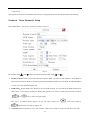
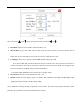
Section 6 Basic Parameter Setup
Enter “Main Menu-Advanced-General” as shown in Fig. 31.
Fig. 31
Move cursor with
¾
and
on the front panel and select item with
and
.
Remote Control: When you use IR controller to operate DVR, you must use this address to select DVR. If
there are more than one DVR in one place, please define different address for each DVR. The default address
is “001”, the value field among 001-255.
¾
DVR Name:Define DVR name. When you access DVR remotely, you can find all the DVR intuitively by
their names .If you want to modify the DVR name, please move cursor to DVR name edit box and press
“
” or “
” key to enter into input mode.
Note: typeⅠ 16 channel model (page.6) can get into input interface by “
“
¾
”, while other model by
”.Details refer to section 4, chapter Ⅲ.
NTP time: Select NTP time as “On”, you can entry “NTP service setup” to set service and interval of NTP.
40
¾
Video Format:Auto adapt according to video input. When video format is changed on operation, you need
to reboot the DVR to take effect.
¾
Alpha: Adjust menu contrast. (Range from00 to 99. 99 stands for low contrast).
¾
Auto logout: “Off”: Only can logout manually in “Maintain” → “Logout”.
“On”: Logout automatically in
the time set in idle time box which will show only “On” is chosen.
¾
Idle time: Length of time during which no operation is executed. Default Idle time: 5 minute.
¾
Screen Saver: This option is special for III type model( with LCD) (page.6), and it can control LCD display time.
DVR will not get into power saving mode if the option is set as 000. And the default value is 5min.
¾
VGA Resolution: Setup VGA output resolution. There are following options: 800×600, 1024×768 and
1280×1024. Default: 1024×768.
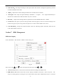
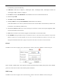
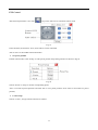
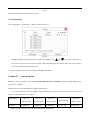
Section 7 HDD Management
HDD State Inquiry
Enter “Main Menu-Rec.& Alarm—HDD” as shown in Fig. 32.
Fig. 32
Move cursor with
and
on the front panel and select item with
and
.
¾
Auto Overwrite: Select it, and it will overwrite the earliest recording when HDD is full.
¾
HDD Alarm: HDD alarm will activate once the capacity of HDD is lower than a value set by user. The
range of warning capacity is among 30 to 99. Alarm mode: buzzer alarm. Default buzzer time is 10 second
41
which can be modified in “Main Menu”→ “Rec. &Alarm”→ “Alarm”.
¾
HDD Format: Select the HDD which will be formatted, press “Enter” key to get into HDD format interface
as shown in Fig. 33.
Fig. 33
Press “Ok” to format HDD.
Note: 1. Do not format a disk while it is recording.
2. Format a HDD will delete all the data in it.
Recording Auto Overwrite
¾
Enter “Main Menu-Rec. &Alarm—HDD” to setup ‘Auto Overwrite’ function: whether activate overwrite
function when HDD is full. Select on then system will overwrite the earliest recording when HDD is full.
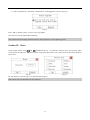
Section 8 Recording
Record Parameter Setup
Enter “Main Menu-Rec. &Alarm—General” as shown in Fig. 34.
42
Fig. 34
Move cursor with
and
on the front panel and select item with
and
.
¾
Channel Number: choose a channel to setup.
¾
Resolution: Options are CIF and D1. Default resolution: CIF
¾
Max Bit Rate: If you select VBR, when the video input has great movement, we need to limit the max bit
rate. The max bit rate selection has relations with resolution. If you select high resolution, you must select
high bit rate. If you select CBR, you can select bit rate size. Default bit rate: 512K
¾
Coding type: There are two options: CBR or VBR. Default coding type: VBR
If you select VBR, DVR will adjust the actual bit rate according to the video movement. When there is
not much movement, DVR will use low bit rate, while there is much movement, DVR will use high bit rate.
In this case, DVR can save HDD usage and network bandwidth.
If you select CBR, DVR will use the fixed bit rate to compress image.
¾
Frame Rate: Frame per second. Default frame rate: “25”
¾
Quality: Define the image quality. There are 5 options: Basic, Medium, Good, High, and Best. High image
quality needs high bit rate size. Default quality: High
In the course of setting up the parameters, if the parameters needed to be set the same in all channels, you can
select ‘ALL’ after finishing the setup of parameters of one channel. The system will prompt a dialog box. When
pressing ‘OK’, parameters setup for all channels will be achieved.
43
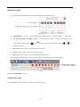
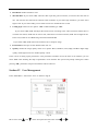
Manual Recording
Press “●” button on the panel to enter into “Manual Record” interface directly.
Fig.35
¾
1-4 CH Status: “√” and “×” on up side stand for recording status. “√”means recording, “×”means idle.
¾
1-4 CH Start/Stop recording: Squares on downside are used to start/stop recording of the
corresponding channel. Press “
” and “
”on the panel to select channels. Press “
start/stop recording.
¾
Record: Press this button to start all channels recording.
¾
Stop: Press this button to stop all channel recording.
¾
Return: Press this button to close the Manual Record window.
Check channel recording status in the red circle of status bar as shown in the following Fig36.
Fig. 36
Please refer Status Bar section.
Schedule Recording
Enter “Main Menu-Rec. &Alarm—Schedule” as shown in Fig. 37
44
” and “
” to
Fig. 37
Move cursor with
and
on the front panel and select item with
and
.
¾
Channel Number: Select a channel for setup
¾
All: After setup one channel. Apply this strategy to all channels
¾
Calendar: “yy/mm/dd/” can be chose on the left of Calendar. For Example : choose 2008-10-20
¾
Time Period: Setup max two period for one day recording at most
¾
Once, Daily, Weekly, Monthly:System default recording period setup is for Once. Recording for Daily,
Weekly or Monthly can also be selected. Take 2008-10-20( Monday) for example, select “Once” means only
recording during the set periods in 2008-10-20, select “Daily” means recording during the set periods
everyday from 2008-10-20, select “Weekly” means recording during the set periods every Monday from
2008-10-20 and select “Monthly” means recording during the set periods at the 20th of every month from
2008-10-20
NOTE: Reset at the same day is available. The later mode will replace the former one. The function
can be applied to holiday setting.
¾
Apply: Press ‘Apply’ to save setting temporarily, if need to set multiple recording periods. For example: set
recording periods in 2008-10-20 and press ‘Apply’, then other recording period could be set in the same
menu without exit. Press ‘OK’ to save all setting permanently.
NOTE: Only press ‘OK’ to save all setting permanently without lost when power is blackout. Press
45
‘Apply’ to save temporarily, all setting will lost when power is off.
In the course of setting up the parameters, if the parameters needed to be set the same in all channels, you can
select ‘ALL’ after finishing the setup of parameters of one channel. The system will prompt a dialog box.
When pressing ‘OK’, parameters setup for all channels will be achieved.
¾
List: Press ‘List’ to list schedule recording time table(Max.120 records) of current channel, records delete
operation is available as shown in Fig. 38
Fig. 38
Four time modes could be showed in this menu including: One day, Daily, Every Tue., Monthly. One day is equal
to ‘Once’
Move cursor to one record with
or
on the front panel then move to the “delete” box. Press ‘ENTER’ to
delete the record.
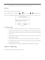
Recording Alarm Setup.
Enter “Main Menu-Rec. &Alarm—Alarm” as shown in Fig. 39
46
Fig. 39
Move cursor with
¾
and
on the front panel and select item with
and
.
Record Duration: Length of recording whenever alarm or motion detection is activated. Default length: 10
minutes.
¾
Pre-record Time: Activate pre-record function including “OFF、5s、15s、25s、30s”. Default pre-record time:
OFF
Note: The max pre-record time of type Ⅱ 8 channel model (page.6) is 5S.
External Alarm Input Setting
Enter “Alarm In” to set external alarm input
¾
Alarm In: Select a alarm input port for setup
¾
Open: This is sensor type.
¾
Alarm Out: Activate alarm out or not.
¾
Rec. CH:When external alarm activated, relevant channel can be selected to record if recording period has
been setup in “Alarm Schedule” menu.
¾
Spot Camera: The channel, which external alarm happened in, can be selected to display as full screen.
¾
Buzzer Time:Buzzer time length when alarm, motion detection, video lost or video shelter is activated.
Default length: 10 seconds.
¾
Schedule: Enter “Alarm Schedule” interface to setup alarm period in which system will activate relevant
47
disposal mode such as buzzer alarm, related channel full-screen display, alarm output, relevant channel
recording if alarm has triggered. Alarm schedule setting is the same as schedule recording setting, please
refer Schedule Recording section.
Motion Detection/Video Lost/ Video Shelter Alarm Setting
Enter ‘Motion’ to set motion detection alarm
Fig. 40
¾
Channel:Select one channel for setting
¾
Motion:Select activate mode including: motion detection, video shelter and video lost.
¾
Sensitivity:Select sensitivity of
motion detection or video shelter. Option including: Highest, High,
Medium, Low, Lowest.
¾
Area Setup:Alarm area should also be set to activate motion detection or video shelter though such function
was selected.
In area setup interface, full screen is the default alarm area. In typeⅠ 4 channel model, type Ⅱ model and
type Ⅲ model (page.6), use direction key to move cursor, press
to cancel chose area, and press
to recover chose area. In typeⅠ 16 channel model (page.6), use direction key to move cursor, press number
“2” key to cancel chose area, and press number “1” key to recover chose area.
48
¾
Rec. CH:When alarm activated, relevant channel can be selected to record if recording period has been
setup in “Alarm Schedule” menu.
¾
Spot Camera: The channel, which motion happened in, can be selected to display as full screen.
¾
Alarm Out: Activate alarm out or not.
¾
Schedule: Enter “Alarm Schedule” interface to setup alarm period in which system will activate relevant
disposal mode such as buzzer alarm, related channel full-screen display, alarm output, relevant channel
recording if alarm has triggered. Alarm schedule setting is the same as schedule recording setting, please
refer Schedule Recording section.
In the course of setting up the parameters, if the parameters needed to be set the same in all channels, you can
select ‘ALL’ after finishing the setup of parameters of one channel. The system will prompt a dialog box.
When pressing ‘OK’, parameters setup for all channels will be achieved.
Note: “Sheltering” and “Video Loss” settings please refer to “Motion” setup.
Alarm Elimination
Click
icon on the status bar to eliminate beep alarm if the alarm is activating.
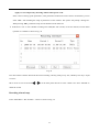
Section 9 Playback/Backup
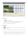
Playback
Press
,
or
in front panel to enter the search interface as show in Fig. 41.
49
Fig. 41
Move cursor with
and
on the front panel and select item with
and
.
¾
From:Set the starting time.
¾
CH:If the “CH” channel is selected as 00, files of all channels will be searched.
¾
All:Recorded files type. The file type options have “All, Timer, Motion, Alarm, Command, and Manual”.
¾
One_CH:This DVR supports 1 CH playback. typeⅠ 4 channel model and type Ⅲ model (page.6) support
4CH playback synchronously for CIF resolution; typeⅠ 16 channel model and type Ⅱ 8 channel model
(page.6) support 1CH playback for CIF resolution.
¾
Card ID: Type Ⅲ model (page.6) support card ID search, and other model haven’t this option.
¾
Search:Search the matched recorded files and display them in the list box. If there is not matched file, “NO
RECORD” will be displayed in the list box.
¾
Playback: Playback the recorded stream directly based on the time section.
¾
File List Box: List the matched files. Files are displayed according to their time, meanwhile display channel
number and file type. You can use “
” and “
” to move the scroll bar to select file. Then press “ENTER”
to playback.
50
¾
Page flip: Use
or
to flip up or down page. Also can input a page number, move cursor on
and
then press “ENTER” button to find the page.
¾
:1. Pause current video playback. 2. Continue playback from pause mode
¾
:Stop current video playback.
¾
:Skip to previous section and play automatically.
¾
:Jump backward a certain time to play.
¾
:Jump forward a certain time to play.
¾
:Skip to next section and play automatically.
¾
-:Play as 1/2, 1/4 of normal speed.
¾
+:Play as 2, 4, 8 times of normal speed.
¾
↗ :Playback in full screen mode.
¾
Hint:When move cursor on a icon, note of the icon will be show in the note box.
Note: If the matched files which you need can’t be found, you can change “From time” and “Recorded files
type” to get expected record files.
Backup
Plug the USB storage device into the USB port marked
. Press
,
or
on the front panel to
enter search interface.
Note: typeⅠ 16 channel model and type Ⅲ model (page.6), plug the USB mouse into either of the USB ports.
In “searching box”, after moved cursor to a certain record section, use “left” or “right” button to choose the
section(“√” signal will show on select box right beside the record section )
When “Merge” is selected, the searched record file should be single channel, and the whole size should be less than
2GB.
If you select “Merge”, system will backup selected files to USB device as one file.
Backup device note:
1. Support Portable HDD storage and flash disk. Portable HDD storage or flash disk has to be formatted
as FAT32 format before backup.
2. A folder named “BACKUP” will be created in the external HDD, and the data will be put in the
51
“BACKUP” folder.
Play recording files after backup
After backup, find the recording(s) in “BACKUP” folder which contains “H264ax.exe” and “Readme.txt” files.
Use a computer which installed “Windows Media Player” and then run “H264ax.exe” according to the hint of
installation. After above steps recordings can be played via “Windows Media Player”.
More details please refer to “Readme.txt”.
PS: Type Ⅲ model’s (page.6) record can be played by Media player directly after backup, and need not to install
any other plug-in software.
Note: 1.USB device and DVR may be damaged if USB device falls off during backup.
2. Do not connect more than 2 USB storage devices to one DVR.
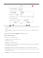
Section 10 Network Setup
Enter “Main Menu-Advanced-Network”, as shown in Fig.42
Static/DHCP
Fig.42
Move cursor with
¾
and
on the front panel and select item with
and
.
Mode: Could choose “Static” or “DHCP”. On “Static Address” status, IP Address, Net Mask, Default
Gateway and DNS should input by user self. On “DHCP” status, IP Address, Net Mask, and Multicast IP will
52
be obtained by system automatically.
¾
ETH mode: Could choose “Adaptive”, “Half Duplex 10M”, “Full Duplex 10M”, “Half Duplex 100M” and
“Full Duplex 100M”. Default is “Adaptive”.
¾
IP Address: Example 192.168.000.100. This IP address must not be conflicted with other IP.
¾
Port: Example 9998.
¾
Net Mask: Example 255.255.255.000.
¾
Gateway Address: Example 192.168.000.001 (Modem/Router local address)
(If the Subnet Mask is set as above, then the first three levels of the IP address and the Gateway address must
be identical. Use the Gateway address first.)
¾
Server Port and Server IP: If you set this IP and port, when there is alarm and exception happened, DVR
will send information to that host IP.
¾
DNS: Please set DNS as local network supplier's IP when DVR is accessed from WAN.
¾
PLATFORM: Setting IP address and port of DVR and connect it with internet. Enter 'Platform' to setup the IP
address of P2P service provider (Default server IP: 60.191.28.165) and enable this function. Access this server
through IE and add the DVR which is going to be operated. The others can be done in the same manner.
PPPoE
Set DNS as local network supplier's IP in “Network Setup” interface. Then select “PPPoE” as shown in Fig.43.
Fig.43
Please “Enable” “PPPoE Setup”, then input the Username and Password provided by ISP. System will use PPPoE
protocol to connect the net with an auto-obtain dynamic IP address.
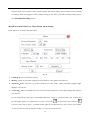
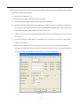
DDNS setup
Set DNS as local network supplier's IP in “Network Setup” interface. Then select “DDNS” as shown in Fig.44.
53
Fig. 44
User can setup DDNS in this interface and access the DVR through the set domain name.
Provider: Could choose “dyndns.org” and “3322.org”.
Host name: Domain name that user register. E.g. If the supplier is “dyndns.org”, and the registered domain name
is “user.dyndns.org”, you can input “user” in “Host name” option.
Username and Password: user name and password registered in supplier’s website.
Section 11 Net Transfer Parameter Setup
Enter “Main Menu-Advanced-Transfer”, as shown in Fig.45
Fig. 45
Move cursor with
¾
and
on the front panel and select item with
Channel number: select relevant channel to setup.
54
and
.
¾
Resolution: Default resolution: CIF.
¾
Max Bit Rate: If you select VBR, when the video input has great movement, we need to limit the max bit
rate. The max bit rate selection has relations with resolution. If you select high resolution, you must select
high bit rate. If you select CBR, you can select bit rate size. Default bit rate: 512K.
¾
Coding Type: There are two options: CBR or VBR. Default type: VBR.
If you select VBR, DVR will adjust the actual bit rate according to the video movement. When there is
not much movement, DVR will use low bit rate, while there is much movement, DVR will use high bit rate.
In this case, DVR can save HDD usage and network bandwidth.
If you select CBR, DVR will use the fixed bit rate to compress image.
¾
Frame Rate: Frame per second. Default frame rate: 25
¾
Quality: Define the image quality. There are 5 options: Basic, Medium, Good, High, and Best. High image
quality needs high bit rate size. Default quality: Good.
In the course of setting up the parameters, if the parameters needed to be set the same in all channels, you can
select ‘ALL’ after finishing the setup of parameters of one channel. The system will prompt a dialog box. When
pressing ‘OK’, parameters setup for all channels will be achieved.
Section 12 User Management
Enter “Main Menu-Advanced-User” as shown in Fig.46.
Fig. 46
Move cursor with
and
on the front panel and select item with
55
and
.
¾
User list: list administrator and new user name. You can modify password, setup local and remote right,
delete user for selected user in this menu.
¾
Admin:Administrator who has supreme right on operation. Choose “Admin”, and choose “Modify” to get
into password modify interface, then press“
”or “
” on front panel to modify password.
Add User
When you login as “Admin”, you can add new user. Select “Add” to enter into “Add User” menu as shown in Fig.
47.
Fig. 47
Press “
” or “
”key to enter into input mode, then you can input the username.
The Viewer’s default authority: information view, playback all channels and monitor all channels.
The operator’s default authority: PTZ control, record management, information view, set parameter, tools,
playback all channels and monitor all channels.
PS: Detail refer to “Authority Setup”.
Setup the password for new user
1、When you login as “Admin”, you can set the password for new user.
In the username list box of “User” menu, use“
”or“
“Authority Setup” menu as shown in Fig. 48:
56
”to choose user. Select “Modify” to enter into the
Fig. 48
Fig. 49
In “Authority Setup” menu, select “Password Set” to enter into “Password Setup” menu as shown in
Fig. 49. Password is composed of number, uppercase and lowercase letter with 6 digit maximum. Select
“Rights Set” to enter into “Right Setup” menu as shown in Fig. 50.
2. Password can be set after logining system as Normal User. Select “User” and press “ENTER” to modify
password in “Password Setup” interface.
Rights Setup
When you login as “Admin”, you can setup the rights for new users.
Use “
” and “
” key to move cursor to the corresponding right items, press “
” and “
” key to
enable or disable the item.
After you finish, press “Enter” button, the user’s rights will be saved. If you press “Cancel” button, the
user’s rights will be aborted.
Fig. 50
Authority:
¾
PTZ Ctrl:PTZ control.
¾
Rec. Manage: General, schedule and alarm recording parameter setting. Start/Stop manual recording
and mute control.
¾
Set Para: General setting, display setting, PTZ setting and net transfer setting included in “Main
menu – Advanced”
¾
Information View: Log, version, online user and HDD information in “menu–information”.
57
¾
Tool: HDD manage, reboot, shut down, maintenance daily and cancel alarm.
Delete user
When you login as “Admin”, you can delete other users.
In “User” interface, move to the username by “
” or “
” and choose it by “
” or “
”.Then select “Delete”
to enter into “System Message” interface as follows and delete it. E.g. the user name is “123” as shown in Fig. 51.
Fig. 51
User manages explain:
¾
User levels have Administrator and Normal user. Can be set 1 Administrator and 29 normal users;
Administrator can modify all users’ password, and Normal user only can modify himself password.
After input 3 times wrong password, system will be locked by itself, and warning, do not allowed to
login any more.
¾
Only Administrator can add user in DVR, Normal user do not allow add any user. And can not add
same name user in one DVR.
¾
Only Administrator can delete user, Normal user do not allow; Administrator can not be deleted.
¾
Only Administrator can set normal user’s rights. Normal user can not set any rights. Administrator
has all rights, and cannot modify.
¾
Only Administrator can use the functions: USB upgrade, Restore parameter and format HDD.
Section 13 Display Setup
Enter “Main Menu-Advanced-Display” as shown in Fig. 52.
58
Fig. 52
Move cursor with
and
on the front panel and select item with
and
.
¾
Channel number: Select one channel for setting.
¾
Cover Channel: whether to display current channel or not
¾
Activate Shielding:Provide you to mask the sensitive area. Move cursor to “Area Set” and set the area.
In the shelter area setup interface, there are four small panes. You can press “
“
”, “
”, “
” and
” or number “1-4” keys to move the cursor. When you choose one pane, use direction keys to move
the pane to your hope position; And press “ENTER” key to fix the pane; Then use direction keys again to
extend the pane. This pane is the shelter area.
After you finish setup, press “ESC” key to exit.
¾
Video Parameters: You can adjust brightness, contrast, hue, and saturation to get the best video image. You
can use
and
key to adjust and can find the video image will be changed at the same time. Range
from00 to 99.
In the course of setting up the parameters, if the parameters needed to be set the same in all channels, you can
select ‘ALL’ after finishing the setup of parameters of one channel. The system will pop-up a dialog box. When
pressing ‘OK’, parameters setup for all channels will be achieved.
Section 14 PTZ Setup
Through DVR_WEB could control PTZ. About the DVR_WEB setting please refer “ChapterⅤ”.
59
Enter “Main Menu-Advanced-PTZ ” as shown in Fig.53.
Fig. 53
Move cursor with
and
on the front panel and select item with
and
.
¾
Channel number: connect channel number of decipherer
¾
RS-485 parameters: Including baudrate, data bit, stop bit, parity bit, flow control, etc. These parameters
must be the same as those of PTZ Protocol.
¾
PTZ Addr: Each PTZ has one different address. Default system configuration: 001.
¾
Protocol: DVR had the following PTZ protocol: PELCO-D、PELCO-P2、PELCO-P1、W110、P3、PLD、
ENKEL、YAAN、SONY、JC4116、PD-NW、PD-CONST、PIH-1016、KRE301、PELCO9760、LILIN、
T3609HD、HD600、KTD、SAMSUNG、ELEC、PANASONIC、FASTRAX、DL-0001.
¾
Speed: PTZ turning speed.
¾
Vertical: Reverse PTZ’s vertical field.
¾
Horization: Reverse PTZ’s horizontal field.
In the course of setting up the parameters, if the parameters needed to be set the same in all channels, you can
select ‘ALL’ after finishing the setup of parameters of one channel. The system will pop-up a dialog box. When
pressing ‘OK’, parameters setup for all channels will be achieved.
Serial Port
PTZ can be controlled by 485(1) or 485(2) port in typeⅠ 16 channel model (page.6).
Enter “Main Menu-Advanced-Serial ” as shown in Fig.54.
60
Fig. 54
Setup parameters for 485(1)R+、R-: Including baud rate, data bit, stop bit, parity bit, flow control and so on,
they have to be consistent with parameters of connected series device(such as keyboard).
PTZ Port: You should select the “Port1” when the 485(1)is connected to PTZ; And you should select the
“Port2” when the 485(2)is connected.
Note: External Keyboard can works only when it’s connected to R+,R- in 485(1) port.
PTZ can be controlled by RS485 or RS232 port in type Ⅲ model (page.6).
Fig. 55
Fig.56
PTZ Port: You should select the “RS485” when the RS485 port is connected to PTZ; And you should select the
“RS232” when the RS232 port is connected.
When temperature or humidity transducer is connected, user can set the parameter in fig.56. If the display value is
inconsistent with the actual situation, user can adjust it by modify coefficient and correction.
Temperature or humidity value displayed =coefficient* value from transducer + correction.
61
PTZ Control
After the PTZ parameter is set, click “
” key on the status bar to enter PTZ control mode.
Fig. 57
In the interface, the direction, zoom, focus and Iris can be controlled.
Auto-cruise is in the middle of direction button.
¾
Set preset position
In PTZ control mode, select “Setup” to enter preset position setup dialog interface as shown in Fig.58.
Fig. 58
Choose “Preset” to setup or call the corresponding preset.
“001” is an order of preset positions and click “Set” to set a preset position, click “Call” to move PTZ to a preset
position;
¾
Cruise Setup
Choose “Cruise”, and get into the interface as follows:
62
Fig. 59
Fig. 60
Line: Select the line of the cruise.
Setup: Get into the interface as like Fig 60 to set line.
Stop Time: The time which the camera stops in the cruise dot.
¾
AUX setup
Choose “AUX” to control lighting and screen wiper.
PTZ can be controlled on DVR_WEB or Netclient. The detail refer to Chapter 5
For typeⅠ 16 channel model (page.6), PTZ control interface can be shown by press “Fn” on front panel.
Section 15
Restore Defaults Setting
Enter “Main Menu-Advanced-Maintenance-Reset” as shown in Fig. 61
Fig. 61
Move cursor with
and
on the front panel and select item with
Select a item to restore default setting.
63
and
.
Section 16 Information Inquiry
Log Information
Enter “Main Menu-Information-Log” as shown in Fig.62.
Fig. 62
Move cursor with
and
on the front panel and select item with
and
.
Input start time and stop time and then move cursor to “Search” button and press “ENTER” key to start searching.
Type include: Alarm (A), Operate (O), Abnormal (E), and All.
When searching is finished, DVR will list all information. You can press “Previous” or “Next” key to view more
information.
Version Information
Enter “Main Menu-Information-Version” as shown in Fig.63.
64
Fig. 63
Check information of current firmware version.
User Information
Enter “Main Menu-Information-Online” as shown in Fig.64.
Fig. 64
List box: Display the remote user name, State and IP address. Use
and
key to move the cursor. If
user presses ‘Enter’ key on one item in list box, affirmation dialog box will appear. When user selects ‘Enter’,
the system will terminate the remote user.
You can turn pages to look over by selecting ‘Previous’ and ‘Next’.
Section 17 System Update
Method 1: You can update system through DVR_WEB Internet or Netclient. About the DVR_WEB setting
please refer “ChapterⅤ”.
Method 2: You can use this function to upgrade the firmware.
(1)Create a file with a name of “update” in the USB storage, and copy the firmware file to this directory and
rename it with special file name. (page.6)
DVR Model
typeⅠ 4
type Ⅱ 4
type Ⅱ 8
typeⅠ 16
type Ⅲ model
channel model
File name
dvr404d.img
channel model
channel model
dvr404db.img
dvr408db.img
Then insert eternal device into USB port of DVR after modification.
65
channel model
dvr404a.img
dvr416d.img
(2)Enter “Main Menu—Advanced—Maintenance—USB Upgrade” as shown in Fig.65.
Fig. 65
Press “OK” to update system, “Cancel” to give up update.
New firmware will be applied after rebooting.
Note: Please DO NOT unplug the flash memory during the entire system updating process.
Section 18 Reset
Under logout status, press
and
simultaneously for 1 second then “Reset” menu will pop-up. Input
correct password and press ‘OK’ then system will pop-up “Reset Item” box. Select items in this menu and press
OK to reset.
Fig. 66
PS: The function is not for typeⅠ 16 channel model (page.6).
Note: Please call your distributor for the password.
66
Fig. 67
ChapterⅤ IE Monitor
Section 1 Introduction
The DVR can be visited and controlled by IE browser. IE provides the functions, such as remote monitor,
local record, PTZ control, Remote control, etc.
Section 2 Installation Requirements
Requirements for the PC hardware for monitoring, through IE access under the normal condition:
CPU: Interl pentium4 2.0GHz and higher
Ram: DDR 512MB and higher
Video card: independent video card with 64M video memory and higher
Network card: 100M
IE version: support IE6.0 and higher
Support system: support windowsXP, windows2000 and higher
Install DirectX9.0 or higher version, adjust hardware acceleration to highest.
Section 3 Network Connection Operation
1. Insure DVR connect the network correctly
2. Using ping ***.***.***.***(DVR IP), check if the network connect correctly.
3. Make sure Web-client net normally used, the user has to insure http port communicate normally.
4. Install the “DVR_WEB_X.XX.XX.msi” in CD. (X.XX.XX is version number)
5. Input http:// and host IP address and http port in IE address bar. For example: if host IP address is
“10.0.0.124” and http port is 998 then input http://10.0.0.124:998 in IE address bar.
Note: If you have not installed “DVR_WEB_X.XX.XX.msi” to your PC which burned in CD, there will be a
attention for installing ActiveX plug-in software in IE when remote access DVR, install it.
67
Section 4 Basic Surveillance Operation
Start Program
Input http://10.0.0.124 (suppose host IP: 10.0.0.124) in the IE address bar, after connected, display the initial
interface with default English language, the user can set another language through click the “Local
Setup”-“Language” at the lower right corner on the main interface.
The main interface shown as Fig.69:
3
1
4
5
4
Fig. 69
The main interface includes the following module:
1. Login/logout
2. Switch the image view scale
3. Video display
4. Shortcut operation
5. Menu setup
The user connect the Host have the limitation, see the following:
a) Login user number: support max.16 users login together at the same time, support login by same
user name.
68
2
b) Video user number: support max.24 users at the same time.
c) Playback user number: support max.4 users at the same time.
Login/logout
1. Click login button at higher right corner on the main interface(Fig69①marks), or right click the video display
area anywhere, or click the menu and setup, the system will pop-up the login interface.
Fig.70
2. On the login interface, input the host user name (default “Admin”), password (default “123456”) and port,
this port is the host’s port, not the http;
3. The user can operate the video connect, display, remote setup, only after login the system.
4. The subtitle auto change “Login” to “Logout” after login, the operation authority auto cancel after logout.
Switch the image view scale
Click the image view scale button ,on right-top of the main interface(fig.69,mark②),can switch the scale at
4:3 and 16:9.
Video Display Area Operation
In the main interface shown as Fig69 ③ is the video display area.
1. Surveillance connects/dis-connect: right click in the video display area, setup the channel connect,
channel dis-connect, channel all connect, channel all dis-connect in the pop-up menu.
2. Full/split screen switch: when playing the video, double click switch to the full screen display. Double
69
click again, return to the original. Also user can click the shortcut button in the bottom to switch to split
screen (1/4/9/16).
3. Image adjust: select the one surveying channel image, the “Picture Adjust” bar is on the right, shows the
surveying image status(brightness, hue, contrast, saturation), adjust the image effects on the host and IE
web, by adjust this items.
Click the “default” button, restore to the default.
4. Local record/local image snap: every split screen has the hover shortcut status bar on the top. Provide
local record and local image snap function.
PTZ Control
Open the surveillance channel, control the PTZ by control the “PTZ Control” status bar on the main interface
right. Shown as Fig71:
Fig.71
1. Preset point setting: preset point available value: 001~127 (different available value depend on the
different PTZ).
Preset point calling: input a preset point number which have set, click “Call” to turn the PTZ to
that preset point.
2. PTZ direction control: control the PTZ direction by click the up, down, left, right, icon on PTZ
control panel.
3. PTZ, camera, IRIS control: adjust focal length, focus, IRIS, by click the “+”and“—”.
70
4. Light, wiper function: provide lamp and wiper open and shutdown function. The PTZ should support
the lamp and wiper function to realize them.
5. Cruise control: in fig69 “
”icon shows the area of cruise control, cruise including auto cruise and
route cruise.
Auto cruise: left click the menu, select the “Automatic”, then startup the PTZ auto cruise.
Route cruise: entry “Advance Setup”-“PTZ”-“Cruise Setup” menu, setup a route include the all
present point. Max.8 routes for setting.
Route stop: click “Stop” in the cruise menu, over auto cruise or route cruise.
Shortcut Operation Button
In the main interface shown as Fig 69④, is the shortcut operation area.
¾
Full/ Split screen switch
1. Split screen (1-screen, 4-screen, 9-screen), by click the screen split button.
2. Screen split button will choose channel number by judging the equipment channel number. As shown fig72,
the 9-screen button unavailable, when the equipment has 4 channels. 8CH DVR can switch to 9-screen.
16CH DVR can switch to 16-screen.
Fig.72
¾
External alarm switch
1. Open/close relevant alarm by click the alarm switch button.
2. Realize the manual control DVR’s external alarm output by this function. Each switch relevant one alarm
output. User can choose open DVR’s external alarm output by this switch.
3. Alarm switch button, will choose available alarm number according to the equipment. (Fig.73)
Fig.73
¾
Circular Monitor , Mute, Intercom
1. Click the Circular Monitor, Mute, Intercom, function button, open/close these function.
2. When open the function, the button will turn to red, return original when closed it.
3. During the circular monitor, do not allow to operate the video display, close the circular monitor before
71
operate the video display.
4. The audio output will be auto closed temporarily, when open the intercom function, and will return to
original after the close the intercom (Fig 74).
Fig.74
¾
Adjust the image
The mark④ at right on the main interface, is image adjust area. The detail operation please see the above
video area operation fig.69 image adjust instruction.
Section 5 Menu Configuration Setup
Menu setup area including: Search&Playback, Information, Rec.&Alarm, Local Setup, Advance Setup and
Remote Control modules.
Recording And Playback
1. Click
entry “Search&Playback” interface.
2. Searching record: select the start time, channel number, model, click “Search”, finds out the qualified
record.
3. Record playback: select the record slice in the search result, double click this slice or drag this slice to the
selected area. Or press “Play”, play the record at this area.
Supports select the multi-slice and continue select by “Ctrl” and “Shit”. Switch playback display screen
(1-screen/4-screen/full screen). Double click the image, show full screen display.
When at playback, user can operate: pause, stop, slow, normal, fast, and mute.
4. Download: select one of the record slice, press “Download” to download the slice (Fig.75).
72
Fig. 75
Info search
1. Click
, entry “Information” interface.
2. Log information search: search the log information in the remote DVR according to the time, model.
3. HDD info: check all online HDD, HDD capacity, HDD spare capacity on the host.
4. System version: check the remote host software version info.
Rec.&Alarm
Click
entry “Rec.&Alarm” interface, setup the remote DVR recording configuration, reference to
“Recording” Section8 ChapterⅣ.
1. Basic record setup: setup the channel resolution, rate, rate type, frame rate, image quality, and auto record
cover.
2. Schedule record setup: setup the channel schedule record time, user can choose today, daily, weekly, monthly.
3. Alarm record setup: setup record time, alarm time, pre-record, alarm input, relevant channel record, alarm
output, spot camera, motion detection in defense time. Video shelter, video lost, are, sensitive etc.
73
Local Setup
Click
entry “Local Setup” interface, setup local configuration, including: language, stream type, transmit
protocol, circular channel quantity, local save route etc.
1. Language selection: provide local IE web language switch and display function.
2. Stream type: select the transmit model, including main stream, sub stream (net transmit code type). The main
stream setup in the “Advance Setup-Transfer”.
3. Transmit protocol: provide TCP, UDP transmit setup.
4. Circular monitor setup: Setup circular monitor display. Including: image number display at once, image stay
time in circular monitor.
5. Local storage path setup: choose local image snap, local record save route.
6. Local surveillance and playback support P/N, adjust the video compression according to the video
headstream itself.
Advance Setup
Click
entry “Advance Setup” interface. These configurations are corresponding to the “Advance Setup”
in the menu in DVRs.
1. System configuration: take reference at “Basic Parameter Setup” Section6 ChapterⅣ.
2. Channel configuration: take reference at “Display Setup” Section13 ChapterⅣ.
3. Network Parameters: including startup DHCP, IP address, Subnet mask, Gateway, Net card speed, ports, host
MAC sits get, PPPoE setup, http port setup and DDNS setup. Take reference at “Network Setup” Section10
ChapterⅣ.
Http port:when use the IE view browser, input the port behind the IP address, such as : IP is192.168.2.3,http
port is 998,input the IE addresshttp://192.168.2.3:998;
4. Net transmit setup: setup Sub stream (Net transmit stream) configuration. Take reference at “Net Transfer
Parameter Setup” Section11 ChapterⅣ.
5. PTZ configuration: Take reference at “PTZ Setup” Section14 ChapterⅣ.
6. User info.: provide remote add or change host name, password, and display all current user name. Take
reference at “User Management” Section12 ChapterⅣ.
74
7. Email function: provide the email function that auto send the emails with alarm log, operation log, exception
log to the host when triggered. Steps:
a)
Select the email function “yes”.
b)
Fill out the email address which the email will send to.
c)
Select triggered model for email: like alarm, operation or exception.
d)
Input the email sender address and email SMTP server address and ports.(use the Ping get the email
server address, such as yahoo email box, SMTP is SMTP.MAIL.YAHOO.COM, support the IP input
and DN(domain name); Input SMTP server ports (Usually 25).
e)
Authority select: ON, OFF. Start SMTP email AMF(Authentication Management Function),avoid to abuse
the email server;
f)
User name, password, sender address, Email title etc, user could write it as they like, sender address
could be virtual address.
When the alarm, operation, abnormal triggered in local, the host will send the information emails
according to the address and setup which have set before. If you have set the remote alarm triggered
input, the host will send the JPEG with the email as well. See the detail fig.76.
Fig. 76
75
Remote control
Click
entry “Remote Control” interface, could control remote record open /close and system maintain
1. Record control: remote open/close the host record.
2. System maintain: provide DVR system image file update, web software update, remote DVR reboot, restore
default (factory default), export Remote system configuration, import remote system configuration,
shutdown system and download Player plug-ins.
Player plug-in: The plug-in named “H264ax.exe” can be downloaded from host end, and installed on PC.
Then the record file can be played by Media Player immediately.
76
Chapter Ⅵ
Frequency Asked Questions
1. Can not control DVR with IR controller, but it’s normal while using the front panel.
1)
Check whether the battery is exhausted. Replace a new battery.
2)
Check whether the address of controller is the same as the ID of DVR. If not, please change the address
of controller at 000 or input the same ID of DVR.
2. Has changed the time or the channel name position in “Display” but why it does not come into effective.
1)
Time and position settings in “Display” are for recording and remote monitoring. Cannot modify the time
position of local monitoring.
2)
System separates them automatically when they are overlapped.
3. Why cannot control the PTZ?
1)
Please check whether the PTZ setup in “PTZ” is setting correctly, including protocol, baud rate and
address.
2)
Please check whether the RS485 cable connection is correct.
4. Why the recording is not work?
1)
Please check HDD connection. If the HDD is not detected by DVR, the recording will sure not working.
2)
Please check whether there is available space of HDD left. If not, Please replace the HDD or set “Yes” in
“Rec. &Alarm”→ “HDD”→ “Auto Overwrite”.
5. Cannot choose options in menu.
Please confirm that you possess the rights. Please login as Admin to check the rights.
6. Please DO NOT modify the system time or format HDD while recording.
7. Active device is requested while using intercom function or output audio for typeⅠ 4 channel model and type
Ⅲ model (page.6). Other type model can not use active device while using intercom function.
8. Connect DVR through DVR_WEB in VISTA: If cannot login, please setting as following: “Control Panel”→
“User Account”→ “Turn User Account Control On or Off”, and uncheck "Use User Account Control
(UAC)...". You'll have to reboot, but the UAC will be off without a Security warning.
9. After Input the host address and connected, web control auto download, if update the new web version, the
original version auto deleted.
10. When ‘Click here to activate control’ floating note box show on screen, please click the box to activate the
77
control.
After activating the control, if one or more problems occur such as channel covered with white lump,
control disappear or right click pop-up no menu, please update patches(KB945007 and KB912945) on
http:\\www.microsoft.com.
11. Open the IE connect interface, under the XP system, if can not download the subtitle normally, please check
the XP system scripting. FileSystemObject (FSO text read and write) if it is closed, close this function will
lead “automation server can not create object”, the WEB language configuration file can not download to
local display, open FSO will solve this problem.
Solution: “start”-“run” input regsvr32 scrrun.dll. Press the “enter”.
12、Connect DVR through DVR_WEB, if the icon or caption can not be displayed, you should close the IE and
then install the “DVR_WEB_XXXXX.msi” which burned in CD (XXXXX is version number).
Appendix 1
HDD Capability Calculate
1. Required HDD capacity for one channel one hour (unit Mbyte):
HDD capacity=bit rate / 8 × 3600 / 1024
The unit of bit rate is Kbit/s.
2. Required one channel HDD capacity (unit Mbyte):
HDD capacity=required HDD capacity of one channel for one hour× daily recording time × number of
recording days
3. Required HDD capacity for all channels timing record (unit Mbyte):
HDD capacity=required one channel HDD capacity × the number of channels
4. Required HDD capacity for all channel alarm records (unit Mbyte):
HDD capacity=required one channel HDD capacity × the number of channels ×Alarm rate
78
Information on Disposal for Users of Waste Electronic Equipment (private
households)
This symbol on the products and /or accompanying documents means
that used electrical and electronic products should not be mixed with
general household waste.
For proper treatment, recovery and recycling, please take these products
to designated collection points, where they will be accepted on a free of
charge basis. Alternatively, in some countries you may be able to return
your products to your local retailer upon the purchase of an equivalent
new product.
Disposing of this product correctly will help to save valuable resources
and prevent any potential negative effects on human health and the
environment which could otherwise arise from inappropriate waste
handling. Please contact your local authority for further details of your nearest designated collection point.
Penalties may be applicable for incorrect disposal of this waste, in accordance with national legislation.
For business users in the European Union
If you wish to discard electrical and electronic equipment, please contract your dealer or supplier for further
information.
Information on Disposal in other Countries outside the European Union
This symbol is only valid in the European Union.
If you wish to discard this product, please contact your local authorities or dealer and ask for the correct method
of disposal.
79