
1
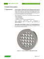
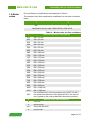
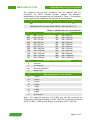
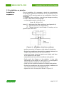
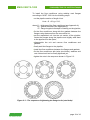
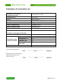
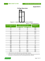
EMIS-VEKTA
1200.UM.PS
27.11.2012
v1.0.5
FLOW CONDITIONER
«EMIS-VEKTA 1200»
www.emis-kip.ru
User manual
Passport
«EMIS», CJSC
Russia, Chelyabinsk
EMIS-VEKTA 1200
Disclaimer
РУКОВОДСТВО ПО ЭКСПЛУАТАЦИИ
"EMIS", CJSC reserves the right to make changes in the design and
documentation of the product without prior notice. If you need additional
information on EMIS equipment, please contact your local dealer or the
head office.
EMIS® and EMIS logo are registered trademarks of "EMIS", CJSC.
Any use of the material of this publication, in whole or in part, without
written permission of the copyright holder is prohibited.
CAUTION!
Before you start operating the flow conditioner, you should carefully
read this manual. Before starting the installation, use or maintenance
of the flow conditioner, make sure that you fully read and understood
the contents of the manual. This condition is necessary to ensure
safe operation and proper functioning of the product.
For advice, contact your local dealer of "EMIS", CJSC or the support
service:
Tel./ Fax: +7 (351) 729-99-12
e-mail: [email protected]
page 2 of 16
EMIS-VEKTA 1200
РУКОВОДСТВО ПО ЭКСПЛУАТАЦИИ
Table of contents
1.1 Applications
4
1.2 Technical data
5
1.3 Pressure drop
5
1.4 Delivery set
5
1.5 Model codes
6
2.1 Safety precautions
8
2.2 Preparation for installation
8
2.3 Installation on pipeline
9
3.1 General recommendations
11
3.2 Periodical inspection
11
3.3 Periodical maintenance
11
4. Storage
4.1 General recommendations
11
5. Transportation
5.1 General recommendations
11
1. Product description
2. Operation
3. Maintenance
12
6. Example of
reclamation act
Appendix A
Outline dimensions and weight
13
Appendix B
Gasket dimensions
14
Passport
15
page 3 of 16
EMIS-VEKTA 1200
РУКОВОДСТВО ПО ЭКСПЛУАТАЦИИ
1 Product description
1.1 Applications
Flow conditioner "EMIS-VEKTA 1200" designed to align the flow
profile of gaseous and liquid media before flowmeters of various
types. Flow conditioner eliminates or significantly reduces the
vortices in the flow, and also reduces the deformation of flow
profile. Due to installation of the flow conditioner it is possible to
use shorter straight pipe before the flowmeter.
Flow conditioner is used mostly in conjunction with the following
types of flowmeters:
• vortex flowmeters;
• ultrasonic flowmeters;
• flowmeters based on pressure differential devices.
Flow conditioner "EMIS-VEKTA 1200" corresponds
disk conditioning plate of «Zanker» type according
GOST R 8.586.1.
to
to
Structurally, flow conditioner is a disc with 32 holes arranged in a
symmetrical circular pattern (Figure 1.1). The thickness of the
disk, diameters and coordinates of the holes correspond to the
requirements of GOST R 8.586.1.
Figure 1.1 – Flow conditioner «EMIS-VEKTA 1200»
page 4 of 16
EMIS-VEKTA 1200
РУКОВОДСТВО ПО ЭКСПЛУАТАЦИИ
Table 1 – Technical data
1.2 Technical data
Parameter
Value
Medium
Liquid, gas, steam
Nominal diameter
15 … 1200 mm
Maximum pressure
According to the pressure of
connection kit flanges
Outline dimensions and
weight *
See Appendix A
Material *
Cast steel,
Stainless steel,
Steel AISI A516-60
* At customer's request other materials and dimensions can be
used.
1.3 Pressure drop
Pressure drop ∆P for flow conditioner "EMIS-VEKTA 1200" can
be calculated in accordance with GOST R 8.586.1 by the formula
2
∆P = ξ·0,5·ρ·w , Pa,
where ξ – coefficient of hydraulic resistance. For flow
conditioner of «Zanker» type ξ=3;
3
ρ – density of the medium in working conditions, kg/m ;
w – average velocity of flow, m/s.
Average velocity of flow calculated as
2
w = 4·Q·1000 / (3,14·D ·3,6), m/s,
3
where Q – instant flow rate, m /h;
D – inner diameter of the pipeline, mm.
1.4 Delivery set
Delivery set includes:
1. Flow conditioner "EMIS-VEKTA 1200".
2. User manual and passport.
3. Connection kit (by request).
page 5 of 16
EMIS-VEKTA 1200
1.5 Model
codes
РУКОВОДСТВО ПО ЭКСПЛУАТАЦИИ
Flow conditioner’s modifications are presented in Table 2.
The example of the flow conditioner’s modification for the order is showed
below.
1
2
050
S
Modification for the order: EMIS-VEKTA 1200 050-S
Table 2 – Model codes for flow conditioner
Nominal diameter of the pipeline
1
015
DN = 15 mm
025
DN = 25 mm
032
DN = 32 mm
040
DN = 40 mm
050
DN = 50 mm
065
DN = 65 mm
080
DN = 080 mm
100
DN = 100 mm
125
DN = 125 mm
150
DN = 150 mm
200
DN = 200 mm
250
DN = 250 mm
300
DN = 300 mm
350
DN = 350 mm
400
DN = 400 mm
500
DN = 500 mm
600
DN = 600 mm
700
DN = 700 mm
800
DN = 800 mm
900
DN = 900 mm
1000
DN = 1000 mm
1200
DN = 1200 mm
For modifications in strict accordance with GOST R 8.586.1
the actual inner diameter of the pipeline XXX in the units of
mm (instead of the nominal diameter) should be specified.
XXX
2
Material of the flow conditioner
C
Cast steel
S
Stainless steel
A516
X
Steel AISI A516-60
Special order
page 6 of 16
EMIS-VEKTA 1200
РУКОВОДСТВО ПО ЭКСПЛУАТАЦИИ
By customer’s request flow conditioner can be supplied with the
connection kit, which includes flanges, gaskets and fasteners.
Modifications of the connection kit are presented in Table 3. The example
of the connection kit modification for the order is showed below.
1
2
050
–
C
3
–
1.6
Modification for the order: EMIS-VEKTA 1200.CK-050-C-1.6
1
015
025
032
040
050
065
080
100
125
150
200
Table 3 – Model codes for connection kit
Nominal diameter of the pipeline
DN = 15 mm
250
DN = 250 mm
DN = 25 mm
300
DN = 300 mm
DN = 32 mm
350
DN = 350 mm
DN = 40 mm
400
DN = 400 mm
DN = 50 mm
500
DN = 500 mm
DN = 65 mm
600
DN = 600 mm
DN = 080 mm
700
DN = 700 mm
DN = 100 mm
800
DN = 800 mm
DN = 125 mm
900
DN = 900 mm
DN = 150 mm
1000
DN = 1000 mm
DN = 200 mm
1200
DN = 1200 mm
2
Material of connection kit flanges
C
Cast steel
S
Stainless steel
A516
X
Steel AISI A516-60
Special order
3
Maximum pressure in the pipeline
1.6
1.6 MPa
2.5
2.5 MPa
4.0
4.0 MPa
6.3
6.3 MPa
10
10 MPa
16
16 MPa
20
20 MPa
X
Special order
Note – For maximum pressure of 2.5 MPa and less the connection kit
flanges are of flat type according to GOST 12820-80, for maximum pressure
above 2.5 MPa – welding neck flanges according to GOST 12821-80.
page 7 of 16
EMIS-VEKTA 1200
РУКОВОДСТВО ПО ЭКСПЛУАТАЦИИ
2 Operation
Installation, operation, maintenance of flow conditioners should
be performed by persons studied this manual and safety
instructions for working on the object of installation.
2.1 Safety
precautions
Installation of flow conditioners in the pipeline and its dismantling
should be performed without pressure in the pipeline.
During installation the hazardous factors are:
• excess pressure in the pipeline;
• high temperature of the medium.
Installation of flow conditioner with flanges which are not
complied with the maximum pressure in the pipeline is prohibited.
2.2 Preparation for
installation
Before installation the flow conditioner, it is necessary to find the
proper place of installation considering the requirements for the
minimum length of straight sections of the pipeline.
Requirements for the length of straight pipe sections before the
flow conditioner (L1 in Figure 2.1), and between the flow
conditioner and the flowmeter (L2 in Figure 2.1) are specified in
the documentation for the corresponding flowmeter.
1 – flow conditioner
2 – flowmeter
Figure 2.1 – Requirements for the length of straight sections of the pipeline
page 8 of 16
EMIS-VEKTA 1200
РУКОВОДСТВО ПО ЭКСПЛУАТАЦИИ
2.3 Installation on pipeline
Installation
sequence
Prior to installation, it is necessary to check the completeness
of the flanges, gaskets and fasteners of the connection kit and
conformity of all mounting parts to the modification of the flow
conditioner.
To install the flow conditioner using flat type flanges according
to GOST 12820 do the following steps:
• cut the pipeline section of length Linst:
Linst = S + 2*Lg + 2*Lf,
where S – thickness of the flow conditioner (see Appendix A);
Lg – gasket thickness (see Appendix B);
Lf – flange thickness minus depth of landing on the
pipeline (see Figure 2.2);
Flow
conditioner
f
Figure 2.2 – Installation of the flow conditioner
• put the connection kit flanges on both sides of the pipeline;
• fix the flow conditioner along with the gaskets between the
flanges using fasteners from the connection kit;
• center the flanges along the pipeline and slightly weld them
to the pipeline at a few spots;
• disassemble and remove flow conditioner and gaskets;
• finally weld the flanges to the pipeline, it may take
dismantling of the section L2 (see Figure 2.1) of the pipeline
between the flow conditioner and the flowmeter;
• install the flow conditioner between the flanges and gaskets;
• fix the flow conditioner with bolts (stud bolts), washers and
nuts. Nuts should not be finally tightened yet;
• tighten the nuts in the sequence shown in Figure 2.3.
page 9 of 16
EMIS-VEKTA 1200
РУКОВОДСТВО ПО ЭКСПЛУАТАЦИИ
To install the flow conditioner using welding neck flanges
according to GOST 12821 do the following steps:
• cut the pipeline section of length Linst:
Linst = S + 2*Lg + 2*Lf,
where S – thickness of the flow conditioner (see Appendix A);
Lg – gasket thickness (see Appendix B);
Lf – flange length minus depth of landing on the pipeline;
• fix the flow conditioner along with the gaskets between the
flanges using fasteners from the connection kit;
• put the assembled unit into the cut section of the pipeline,
center the flanges along the pipeline and slightly weld them
to the pipeline at a few spots;
• disassemble the unit and remove flow conditioner and
gaskets;
• finally weld the flanges to the pipeline;
• install the flow conditioner between the flanges and gaskets;
• fix the flow conditioner with bolts (stud bolts), washers and
nuts. Nuts should not be finally tightened yet;
• tighten the nuts in the sequence shown in Figure 2.3.
Figure 2.3 – The sequence of tightening the flange bolts (stud bolts)
page 10 of 16
EMIS-VEKTA 1200
РУКОВОДСТВО ПО ЭКСПЛУАТАЦИИ
3 Maintenance
3.1 General
recommendations
It is recommended to perform periodic inspection and routine
maintenance of the flow conditioner. Period of these operations
is set by the operating organization.
3.2 Periodical
inspections
On periodic inspection the flow conditioner and its installation
place must be inspected without dismantle. One should pay
attention to:
• appearance – there should not be dents, cracks and other
damage to the outer surfaces of the product and its fixing
flanges;
• presence of fasteners - all stud bolts must be in place and
tightened;
• absence of traces of corrosion.
3.3 Periodical
maintenance
On periodic maintenance the flow conditioner should be
dismantled and the following operations should be performed:
• clean the surface of the product from dirt and corrosion;
• replace gaskets (their dimensions are given in Appendix B);
• replace worn fasteners.
4 Storage
4.1 General
recommendations
Flow conditioners can be stored in heated and non-heated
rooms, providing the air doesn’t contain substances, which
are corrosive for the product. If necessary, the surface of the
product may be covered with corrosion oils.
5 Transportation
5.1 General
recommendations
Flow conditioners can be transported by all kinds of transport
without restrictions.
page 11 of 16
EMIS-VEKTA 1200
РУКОВОДСТВО ПО ЭКСПЛУАТАЦИИ
6 Example of reclamation act
Customer of the product
(organization name)
«Organization», CJSC
Contact person
John Smith
Phone
(495)12293333
Modification of the flowmeter
EMIS-VEKTA 1200 050-S
Serial number
123
Date of manufacturing
14th March, 2012
Date of commissioning
25th May, 2012
Date of fault detection
18th July, 2012
Customer’s description of the fault
Possible reasons of the fault
Measured medium
о
Parameters of the
measured medium
water
Temperature, С
+92
Pressure, bar
2.3
Estimated flow
rate, kg/h
6.5
Conclusion of the customer
Customer representative:
_______
date
Representative or organization
performed installation and
commissioning:
_______
date
________________________
name
________________________
name
________
signature
________
signature
page 12 of 16
EMIS-VEKTA 1200
РУКОВОДСТВО ПО ЭКСПЛУАТАЦИИ
Appendix A
D
Outline dimensions
S
Figure A.1 – Outline dimensions of the flow conditioner
Table A.1 – Outline diimensions
Nominal diameter DN,
mm *
15
25
32
40
50
65
80
100
125
150
200
250
300
350
400
500
600
700
800
900
1000
1200
Outline dimensions, mm
S
D
2.3
39
3.8
57
4.8
65
5
75
7
87
8
109
10
120
13
149
16
175
20
203
26
259
33
312
39
363
46
421
52
473
65
575
78
677
91
777
104
877
117
980
130
1080
156
1280
Weight, kg
0.03
0.05
0.09
0.15
0.28
0.4
0.7
1.4
2.2
3.8
7.8
14
22
34
48
87
141
213
306
426
568
943
1. * Dimensions for other DN must be specified when ordering.
2. Dimensions of flow conditioner plates produced by special order may vary from the
ones given in the table above and must be specified when ordering.
page 13 of 16
EMIS-VEKTA 1200
РУКОВОДСТВО ПО ЭКСПЛУАТАЦИИ
Appendix B
Gasket dimensions
s=2
B
D
Figure B.1 – Gasket drawing
Material of gaskets is Paronite PON 2 GOST 481-80.
Dimensions are presented in Table B.1.
Table B.1 – Gasket dimensions
DN, mm
D, mm
B,mm
15
25
32
40
50
65
80
100
125
150
200
250
300
350
400
500
600
700
800
900
1000
1200
19
33
39
46
59
78
91
110
135
161
222
273
325
377
426
530
630
720
820
920
1020
1220
39
57
65
75
87
109
120
149
175
203
259
312
363
421
473
575
677
777
877
980
1080
1280
Note: For special orders with agreement with the customer the gasket can
be of different type or absent.
page 14 of 16
EMIS-VEKTA 1200
РУКОВОДСТВО ПО ЭКСПЛУАТАЦИИ
Passport
Basic information
Flow conditioner «EMIS-VEKTA 1200»
Manufactured by «EMIS», CJSC, Russian Federation, 454007,
Chelyabinsk, Lenin St. 3, http://www.emis-kip.ru
Serial number ____________________________
Date of manufacturing _____________________
Delivery set
Delivery set
□ EMIS-VEKTA 1200
□ EMIS-VEKTA 1200.UM.PS
□ EMIS-VEKTA 1200. CK
Acceptance
Flow conditioner
«EMIS-VEKTA 1200»
User manual, Passport
Connection kit
Flow conditioner “EMIS-VEKTA 1200” meets the requirements of
design documentation and found qualified for operation.
Responsible for acceptance _____________________________
Packaging
Flow conditioner “EMIS-VEKTA 1200” is packed in accordance with
the requirements of design documentation.
Date of packaging ____________________________________
Responsible for packaging _____________________________
Warranty
Warranty period is 36 months from the date of commissioning, but
not more than 42 months from the date of delivery of the product.
Commissioning
Commissioning date _____________________________
Position, name and signature of the person responsible for
commissioning
____________________________________________________
page 15 of 16
www.emis-kip.ru
«EMIS», CJSC
Sales department
«Electronic and Mechanical
Measurement Systems»
Phone (351) 729-99-12,
Ext. 111,121,131
Fax (351) 729-99-13
Russian Federation
454007, Chelyabinsk
Lenin St.,3
[email protected]
Customer support and
service department
8-912-303-00-41
[email protected]
Marketing department
Phone (351) 729-99-12
Ext. 331, 332
Fax (351) 729-99-13
[email protected]


![[U2.03.06] Réalisation d`une étude génie civil avec câbles de](http://vs1.manualzilla.com/store/data/006352937_1-7d2c1e89f4f38d00e2b2a50cff8b1b1d-150x150.png)