1
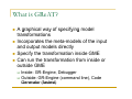
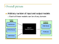
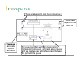
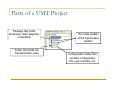
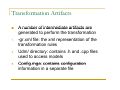
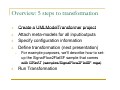
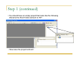
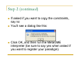
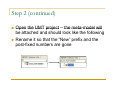
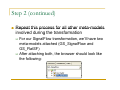
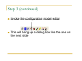
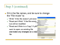
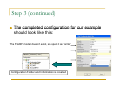
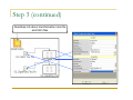
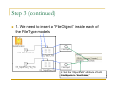
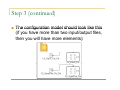
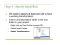
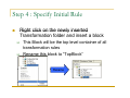
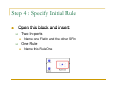
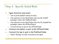
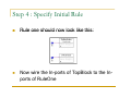
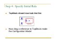
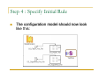
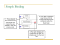
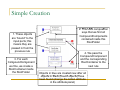
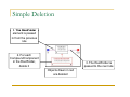
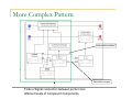
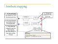
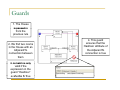
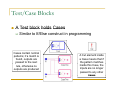
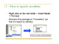
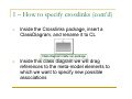
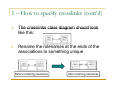
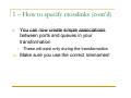
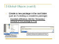
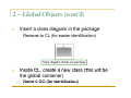
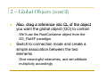
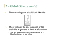
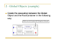
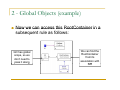
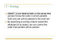
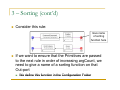
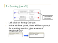
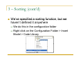
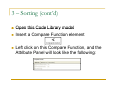
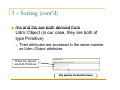
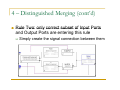
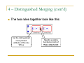
GReAT : The Graph Rewriting g g and Transformation Language Daniel Balasubramanian Graduate Research Assistant,, ISIS Copyright © Vanderbilt University/ISIS 2007 Overview Introduction What is GReAT? Overall picture Example rule Wh Where to t begin b i Running the transformation What is GReAT? A graphical way of specifying model transformations Incorporates p the meta-models of the input p and output models directly Specify the transformation inside GME Can run the transformation from inside or outside GME Inside: GR-Engine, Debugger Outside: GR-Engine (command line), Code Generator (fastest) Overall picture Arbitrary number of input and output models Each of these models can be of any domain I Inputs t Outputs FSM Model FSM Model HFSM Model GReAT Transformation TM Model ASM Model Transformations Sequence of explicitly sequenced transformation rules Rule patterns are drawn using UML notation with elements from the meta-models Once a pattern is found 1. 2. 3 3. 4. Existing elements can be deleted New elements can be created Elements can be selected and passed to the next rule Attributes of any existing objects can be accessed and manipulated Example rule These are passed in from the previous rule Th These pass objects to the next rule This gives access to object’s attributes For every LocalPort we find in the incoming Compound Component, we create a new Queue, and we create a new simple association between the port and the queue Overall process All transformations begin by creating a new UMLModelTransformer (UMT) project in GME This is a specific GME paradigm; that is, it is a modeling language for creating model transformations What is defined in this project? (next slide) What is inside a UMT Project? Configuration information 1 1. • Gives information about the input and output files and the names of the meta-models,, etc. Transformation rules 2. • A sequence of patterns that are matched; if a match occurs, an action can take place (objects can be created, destroyed, or attributes changed) h d) Parts of a UMT Project Package that holds temporary class diagrams (crosslinks) Folder that holds the transformation rules The meta-models of the input/output models Configuration folder that contains configuration info, user includes, etc. Performing the transformation After giving the configuration information and specifying the transformation rules, we have three ways y of p performing g the transformation GR-Engine : interpreter, used while developing transformation for fast testing Debugger : used during development to debug transformations Code Generator : used once a transformation reaches a mature state – produces executable code (very fast) Transformation Artifacts 1 1. 2 2. 3 3. A number of intermediate artifacts are generated to perform the transformation -gr xml file: the xml representation of the -gr.xml transformation rules Udm/ directory: contains .h h and .cpp cpp files used to access models Config mga: contains configuration Config.mga: information in a separate file Next tutorials Initial setup Defining rules Advanced features GReAT Tutorial Part I : p Initial Setup Daniel Balasubramanian Graduate Research Assistant,, ISIS Copyright © Vanderbilt University/ISIS 2007 Overview: 5 steps to transformation Create a UMLModelTransformer project Attach meta-models for all input/outputs Specify configuration information Define transformation (next presentation) 1 1. 2. 3 3. 4. • 5. For example F l purposes, we’ll ’ll d describe ib h how to setup the SignalFlow2FlatSF sample that comes with GReAT (samples/SignalFlow2FlatSF.mga) (samples/SignalFlow2FlatSF mga) Run Transformation Step 1 : Creating the project In GME : File > New Project… Select UMLM d lT UMLModelTransformer f Select Create New Create Project File Give filename Step 1 (continued) • You should have an empty project that looks like the following -Rename the Root Folder element to “RF” • Now save the project and exit Step 2 : Attaching meta-models Open the meta-models meta models for all input and output models (may have to repeat this several times) – these are MetaGME style MMs MM Invoke the MetaGME2UMT interpreter Select the UMT project you created in step 1 when asked where to save Step 2 (continued) If asked if you want to copy the constraints, say no You’ll see a dialog g like this: Click OK, and then run the MetaGME interpreter (be sure to say yes when asked if you want to register your paradigm) Step 2 (continued) Open the UMT project -- the meta-model meta model will be attached and should look like the following Rename it so that the “New” New prefix and the post-fixed numbers are gone Step 2 (continued) Repeat this process for all other meta-models meta models involved during the transformation For our SignalFlow transformation, we we’llll have two meta-models attached (GS_SignalFlow and GS_FlatSF) After attaching both, the browser should look like the following: Step 3 : Specify Configuration The configuration information gives information on input/output files, metainformation,, etc. The configuration model editor (interpreter with GReAT) assists in quickly creating configurations Step 3 (continued) Invoke the configuration model editor This will bring up a dialog box like the one on th nextt slide the lid Step 3 (continued) Fill in the file names, and be sure to change the “File mode” to: “Write” if the file doesn’t yet exist “Read and Write” if the file exists but will be modified “R d and “Read dW Write it tto a C Copy”” if you want to open an existing file and make any changes on a new file Step 3 (continued) The completed configuration for our example should look like this: The FlatSF model doesn’t exist, so open it as “write” Configuration Folder and Information is created Step 3 (continued) Describes info about transformation rules file and Udm files Step 3 (continued) 1. We need to insert a “FileObject” FileObject inside each of the FileType models 2. Set the “ObjectPath” attribute of both FileObjects to “RootFolder;” RootFolder; Step 3 (continued) The configuration model should look like this (if you have more than two input/output files, then yyou will have more elements): ) Step 4 : Specify Initial Rule We need to specify at least one rule to have a working transformation Insert a transformation folder in the root folder in your project 1 1. 2. 3 3. Right click on Root Folder (named RF) Select Insert Folder Select Transformation Step 4 : Specify Initial Rule Right click on the newly inserted Transformation folder and insert a block This Block will be the top level container of all transformation rules Rename this block to “TopBlock” Rename Step 4 : Specify Initial Rule Open this block and insert: Two In-ports Name one FlatIn and the other SFIn One Rule Name this RuleOne Step 4 : Specify Initial Rule Open RuleOne and insert: Two In-ports (default names are fine) One reference to the RootFolder from the GS_FlatSF paradigm di (name ( this thi FlatRootFolder) Fl tR tF ld ) One reference to the RootFolder from the GS_SignalFlow paradigm (name this SFRootFolder) Connect the top In-port to the SFRootFolder Connect the bottom In-port to the SFRootFolder Connect the top In-port to the FlatRootFolder Select “Binding” for both connection role types Step 4 : Specify Initial Rule Rule one should now look like this: Now wire the In-ports of TopBlock to the Inports of RuleOne Step 4 : Specify Initial Rule TopBlock should now look like this: Now drag a reference to TopBlock inside the Configuration Model Step 4 : Specify Initial Rule The configuration model should now look like this: Step 4 : Specify Initial Rule Connect the FileObjects to the In-ports In ports of TopBlock This passes the Root Folders of the input files to the transformation Next tutorial Defining transformation rules Running the transformation GReAT Tutorial Part II : Transformation Rules Daniel Balasubramanian Graduate Research Assistant,, ISIS Copyright © Vanderbilt University/ISIS 2007 Overview The easiest way to understand the semantics of rules is through examples We’llll start from simple rules and work to We complex patterns Simple Binding 1. These objects are “bound” to the input ports; this means they are passed in from the previous rule 2. This UML composition says that we find all CompoundComponents contained inside this RootFolder 3. For each Compound 3 Component we find, we simply pass it to the next rule Simple Creation 1. These objects are “bound” to the input ports; this means they are passed in from the previous rule 3. For each p p CompoundComponent we fine, we create a RootContainer inside the RootFolder 2 Thi 2. This UML composition iti says that we find all CompoundComponents contained inside this RootFolder 4. W 4 We pass the h CompoundComponent and the corresponding RootContainer to the next rule Objects in blue are created new after all objects bj t iin bl black k (b (bound d objects) bj t ) h have been found (change the Action attribute in the attribute panel) Simple Deletion 1. The RootFolder 1 element is passed in from the previous rule 2. For each CompoundComponent in the RootFolder, delete it 3. The RootFolder is passed to the next rule Objects drawn in red are deleted More Complex Pattern Association matched Association created Finds a Signal connection between ports in two different levels of Compound Components Attribute mapping 1. The RootFolders 1 are passed in from the previous rule 2. For each House, we create a new PurchaseOrder 3. The attribute mapping sets the name of the P h PurchaseOrder O d tto the name of the House 4. These are passed to the next rule Guards 1. The House is passed in from the previous rule 2. We find two rooms in the House with an AdjacentTo connection between them 3. A match is only valid if the expression in the guard “HasDoor” evaluates l t to t true t 4. This guard 4 ensures that the HasDoor attribute of the AdjacentTo connection is true Test/Case Blocks A Test block holds Cases Similar to If/Else construct in programming Cases contain C i normall patterns; if a match is found, outputs are passed to the next rule, otherwise no outputs are produced A Cut element inside a Case means that if the p pattern matches inside this Case, the inputs are no longer passed to any other Cases GReAT Tutorial Part III : Advanced Features Daniel Balasubramanian Graduate Research Assistant,, ISIS Copyright © Vanderbilt University/ISIS 2007 Overview 1 1. 2. 3 3. 4. Crosslinks Global Objects Sorting Distinguished Merging 1 - Crosslinks Often in a transformation transformation, we need to be able to create and subsequently match associations that are not p present in the metamodels These can even be between elements of different meta-models 1 - Crosslinks Consider the SignalFlow2FlatSF example In order to flatten the hierarchy, we need to be able to associate Ports in the GS_SignalFlow g MM with Queues in the GS_FlatSF MM These associations are between elements belonging to different meta-models Solution: specify this with crosslinks 1 – How to specify crosslinks 1 1. 2 2. Right click on the root folder > Insert Model > Package Rename this package to “Crosslinks” Crosslinks (so that it’s easier to identify) This is our newly inserted package 1 – How to specify crosslinks (cont’d) 3. Inside the Crosslinks package, insert a ClassDiagram, and rename it to CL Class diagram inside our package 4. Inside this class diagram we will drag references to the meta-model elements to which we want to specify new possible associations 1 – How to specify crosslinks (cont’d) Inside the class diagram (CL), drag references to any MM elements you want to be able to associate with each other 5. 1. For our SignalFlow example, we’ll drag a reference to the Queue from the GS_FlatSF MM, and a reference to the PortBase from the GS_SignalFlow MM Switch to connection mode and connect the elements 6. 1. Choose Association for the connection role type 1 – How to specify crosslinks (cont’d) 7 7. The crosslinks class diagram should look like this: 8. Rename the rolenames at the ends of the associations to something unique Before renaming g rolenames After renaming g rolenames 1 – How to specify crosslinks (cont’d) You can now create simple associations between ports and queues in your transformation 9 9. 1. 10 10. These will exist only during the transformation Make sure you use the correct rolenames! 2 – Global Objects Motivation: we don don’tt always want to have to explicitly pass an object between every rule Solution: create a global container that can contain objects The global container contains the objects you don’t want to have to pass between rules 2 Global Objects (cont’d) Create a new package in the root folder (just as if creating a crosslinks package) 1 1. • Important difference: Set the “Temporary” Temporary attribute of this package to True Setting Temporary attribute to true Inserting Package 2 – Global Objects (cont’d) Insert a class diagram in the package 2. • Rename to CL (for easier identification) Class diagram inside our package Inside CL CL, create a new class (this will be the global container) 3. • Name it GO (for identification) 2 – Global Objects (cont’d) Also, drag a reference into CL of the object Also you want the global object (GO) to contain 4 4. • We ll use the RootContainer object from the We’ll GS_FlatSF paradigm Switch to connection mode and create a simple association between the two elements 5. • Give meaningful rolenames, and set attribute multiplicity accordingly 2 – Global Objects (cont’d) 6. The class diagram should look like this: 7. There will now be one instance of GO available anywhere in the transformation 1. We can associate it with an instance of a RootContainer in our rules 2 - Global Objects (example) Create the assocation between the Global Object and the RootContainer in the following way: y Notice we don’t pass GO through an Out-port 2 - Global Objects (example) Now we can access this RootContainer in a subsequent rule as follows: GO has h global l b l scope, so we don’t need to pass it along p g We can find the RootContainer from its association with GO 3 – Sorting GReAT is non-deterministic non deterministic in the sense that we don’t know the order in which packets from one rule will be p passed to the next rule By specifying a sorting criterion based the attributes of an object, we can control the order that packets will be passed 3 – Sorting (cont’d) Consider this rule: Give name of sorting function here If we want to ensure that the Primitives are passed to the next rule in order of increasing argCount, we need to give a name of a sorting function on that Out-port We define this function in the Configuration Folder 3 – Sorting (cont’d) 1. Left-click on this Out-port 1. 2. Left click on the top Out-port In the attribute panel, there will be a prompt for a sorting function; give a name of “A C F “ArgCmpFunc” ” 3 – Sorting (cont’d) We ve specified a sorting function We’ve function, but we haven’t defined it anywhere We do this in the configuration folder Right click on the Configuration Folder > Insert Model > Code Library 3 – Sorting (cont’d) Open this Code Library model Insert a Compare Function element Left click on this Compare Function, and the Att ib t Panel Attribute P l will ill llook k lik like th the ffollowing: ll i 3 – Sorting (cont’d) rhs and lhs are both derived from Udm::Object (in our case, they are both of type yp Primitive)) Their attributes are accessed in the same manner as Udm::Object attributes These two objects are both Primitives We specify the function here 3 – Sorting (cont’d) Add the following to Function Body The names of the two incoming parameters t our sorting to ti function f ti are lhs lh and d rhs h Our rule states that lhs will be before rhs in a li t if itits argCount list C t iis lless th than th the argCount C t off rhs 3 – Sorting (cont’d) We can also insert a User Code Library element into the Code Library model This gives us the ability to include other headers and libraries that we can reference in any compare functions See user manual for full details 4 – Distinguished Merging Consider a situation such as the following: We want to connect the output ports of RuleOne to the Input p p ports of RuleTwo in a one to one manner However, we cannot simply find all Out-ports in RuleOne and all In-ports in RuleTwo We only need a subset of the matches 4 – Distinguished Merging (cont’d) We divide this into two rules: First rule: select only a subset of matches to pass to the next rule ((the correct Out-ports p and Inports) We want these three matches Second rule: connect the ports 4 – Distinguished Merging (cont’d) Rule one: Specify the same sorting f function ti on each h output t t port to sort the ports by ycoordinate Also set the “Distinguished cross product” attribute of this rule to true 4 – Distinguished Merging (cont’d) Rule Two: only correct subset of Input Ports and Output Ports are entering this rule Simply create the signal connection between them 4 – Distinguished Merging (cont’d) The two rules together look like this: Set the distinguished cross product attribute of this rule t true to t Specify a sorting function on both of these output ports