1
INVERTER Plug-in option PRE-OPERATION INSTRUCTIONS 1 INSTALLATION 2 INVERTER SETTINGS 3 REGISTER NUMBERING 4 CONFIGURATION STUDIO 5 WEB SERVER 6 FILESYSTEM 7 FIRMWARE 8 A7NETH-2P INSTRUCTION MANUAL Ethernet multiprotocol communication interface December 2015 Thank you for choosing this inverter plug-in option for the Mitsubishi 700 Series Inverter. This instruction manual provides handling information and precautions for use of this equipment. Incorrect handling may cause unexpected failures or damage. In order to ensure optimal performance, please read this manual carefully prior to use of the equipment. Please forward this manual to the end user of the equipment. This section pertains specifically to safety issues Do not attempt to install, operate, maintain or inspect this product until you have read through this instruction manual and any related documents carefully, and can use the equipment properly. Do not use this product until you have a full working knowledge of the equipment, safety information and instructions. In this instruction manual, the safety instruction levels are classified into "WARNING" and "CAUTION" levels. WARNING Assumes that incorrect handling may cause hazardous conditions resulting in death or severe injury. CAUTION Assumes that incorrect handling may cause hazardous conditions resulting in moderate or slight injury, or may cause physical damage only. Please note that even the level may lead to serious consequence depending on conditions. Please be sure to follow the instructions of both levels as they are critical to personnel safety. SAFETY INSTRUCTIONS 1. Electrical Shock Prevention WARNING • Do not open the front cover of the inverter while power is on or while the inverter is running, as an electrical shock may result. • Do not operate the inverter with the front cover or wiring cover removed, as accidental contact with exposed high-voltage terminals and internal components may occur, resulting in an electrical shock. • If power is off, do not remove the front cover except when necessary for wiring or periodic inspection. While the front cover is removed, accidental contact with exposed highvoltage terminals and internal components may occur, resulting in an electrical shock. • Prior to starting wiring or inspection, confirm that input power to the inverter has been switched off via observation of the inverter’s display panel. Additionally, wait for at least 10 minutes after removal of input power, and then confirm that all residual voltage has been dissipated by using a voltage meter. Internal DC bus capacitors may contain high voltages for several minutes after removal of input power, resulting in a dangerous situation should anything come into contact with them. • All personnel involved in the installation or inspection of this equipment should be fully competent to perform the required work. • Always install plug-in options prior to wiring main power. • Do not touch the plug-in option with wet hands. • Do not subject the cables to scratches, excessive stress, heavy loads or pinching. A-1 2. Injury Prevention 3) Usage CAUTION • To prevent explosions or similar damage, apply only the voltages specified in the instruction manual to each terminal. • To prevent explosions or similar damage, ensure that all cables are properly connected to the correct terminals. • To prevent explosions or similar damage, observe all wiring polarity indicators. • To prevent burns from hot components, do not touch the inverter while power is on, or for some time after power is removed. 3. Additional Instructions Please note the following points to prevent equipment damage, injury or electrical shock. 1) Transportation and Mounting CAUTION • Do not install or operate the plug-in option if it is damaged or has parts missing. • Do not stand on or rest heavy objects on the equipment. • Check that the mounting orientation is correct. • Prevent conductive items such as screws and metal fragments, or flammable substances such as oil from entering the inverter. 2) Trial Run CAUTION • To prevent unexpected equipment movement, confirm and adjust all required parameters prior to starting operation. A-2 WARNING • Do not modify the equipment. • Do not remove any inverter or option parts unless specifically instructed to do so in this manual. CAUTION • Performing a “parameter clear” or “all parameter clear” will reset all inverter parameters to their factory default settings. After performing one of these operations, remember to reenter any custom parameter values prior to starting operation. • To prevent damage from electrostatic discharge, always touch a grounded piece of metal prior to touching any equipment. 4) Maintenance, Inspection and Parts Replacement CAUTION • Do not perform hi-pot tests on the equipment. 5) Disposal CAUTION • Contact the local or state environmental agency in your area for details on the disposal of electrical components and packaging. 6) General Instructions For clarity purposes, illustrations in this manual may be drawn with covers or safety guards removed. Ensure all covers and safety guards are properly installed prior to starting operation. − CONTENTS − 1 PRE-OPERATION INSTRUCTIONS 1 1.1 Product Overview ................................................................................................................. 1 1.2 Features and Specifications ................................................................................................ 3 1.3 Inverter Compatibility......................................................................................................... 14 1.4 Unpacking and Product Confirmation .............................................................................. 16 1.4.1 Shipment Confirmation............................................................................................................................. 16 1.4.2 Component Overview .............................................................................................................................. 18 1.5 LED Indicators .................................................................................................................... 19 1.5.1 Port Status LED Description .................................................................................................................... 19 1.5.2 Standard LED Description........................................................................................................................ 20 1.5.3 EtherCAT LED Description ...................................................................................................................... 21 2 INSTALLATION 23 2.1 Pre-Installation Instructions .............................................................................................. 23 2.2 A700 & F700 Installation Procedure.................................................................................. 24 2.2.1 Installation of the Communication Option LED Display Cover ..................................................................24 2.2.2 Installation of the Communication Option on Control Board .....................................................................25 I 2.3 E700 Installation Procedure............................................................................................... 27 2.4 Wiring .................................................................................................................................. 28 3 INVERTER SETTINGS 29 3.1 Network Setting .................................................................................................................. 30 3.2 Operation Mode Setting ..................................................................................................... 32 3.2.1 Operation Mode Indication ....................................................................................................................... 32 3.2.2 Operation Mode Switching & Comm. Startup Mode (Pr. 79, Pr. 340) .........................................................33 3.3 Operation & Speed Command Source (Pr. 338, Pr. 339, Pr. 550) ...................................... 37 3.4 Communication EEPROM Write Selection (Pr. 342) ......................................................... 41 4 REGISTER NUMBERING AND BEHAVIOR 42 4.1 Register Numbers............................................................................................................... 42 4.2 Scanned Registers ............................................................................................................. 45 4.3 Inverter Command Register............................................................................................... 47 4.4 Frequency Command Register.......................................................................................... 48 4.5 Operation Mode Register ................................................................................................... 49 4.6 Inverter Reset Register ...................................................................................................... 49 II 4.7 Alarm History Clear Register ............................................................................................. 50 4.8 All Parameter Clear Register ............................................................................................. 50 4.9 Inverter Status Register ..................................................................................................... 51 4.10 Operation Mode Status Register ....................................................................................... 52 4.11 Alarm History Codes .......................................................................................................... 52 5 MITSUBISHI CONFIGURATION STUDIO 53 5.1 Overview.............................................................................................................................. 53 5.2 General Object Editing Activities ...................................................................................... 58 5.3 Ethernet Settings ................................................................................................................ 61 5.3.1 Authentication .......................................................................................................................................... 61 5.3.2 Network Configuration.............................................................................................................................. 62 5.4 Internal Logic Settings ....................................................................................................... 62 5.4.1 Fail-safe Values ....................................................................................................................................... 62 5.4.1.1 Overview ....................................................................................................................................... 62 5.4.2 Timeout Time ........................................................................................................................................... 63 5.4.2.1 Timeout Object Configuration ........................................................................................................ 63 5.5 Discovery over Ethernet .................................................................................................... 65 5.6 Manage Device Parameters ............................................................................................... 66 III 5.7 Backup and Restore Parameters ...................................................................................... 68 5.8 Restore Factory Settings ................................................................................................... 71 5.9 Help...................................................................................................................................... 71 6 6.1 6.2 EMBEDDED WEB SERVER Overview.............................................................................................................................. 72 Monitor Tab ......................................................................................................................... 74 6.2.1 6.2.2 6.2.3 6.2.4 6.2.5 6.3 Information Window ................................................................................................................................. 74 Parameter Group Selection List ............................................................................................................... 74 Parameter List.......................................................................................................................................... 75 Parameter List Filter................................................................................................................................. 77 Radix Selection ........................................................................................................................................ 77 Dashboard Tab ................................................................................................................... 79 6.3.1 6.3.2 6.3.3 6.3.4 6.4 72 Information Window ................................................................................................................................. 80 Gauge Window Navigation....................................................................................................................... 80 Gauge Window Configuration .................................................................................................................. 81 Submitting Changes................................................................................................................................. 86 Customizing the Embedded Web Server .......................................................................... 87 6.4.1 Customization Overview .......................................................................................................................... 87 6.4.2 XTPro Overview....................................................................................................................................... 88 IV 6.4.3 XTPro Web Browser-Based Implementation ............................................................................................ 88 6.4.4 XTPro HMI-Based Implementation........................................................................................................... 90 6.4.5 XTPro Supported Commands .................................................................................................................. 91 7 FILESYSTEM 92 7.1 Overview.............................................................................................................................. 92 7.2 USB with Windows Explorer.............................................................................................. 94 7.3 FTP With Windows Explorer .............................................................................................. 95 7.4 Loading New Web Server Content .................................................................................... 97 8 FIRMWARE 98 8.1 Overview.............................................................................................................................. 98 8.2 Update Procedure............................................................................................................... 98 9 9.1 PROTOCOL-SPECIFIC INFORMATION 100 Modbus/TCP...................................................................................................................... 100 9.1.1 9.1.2 9.1.3 9.1.4 Overview ................................................................................................................................................ 100 Holding & Input Registers ...................................................................................................................... 101 Coil & Discrete Input Mappings .............................................................................................................. 102 Connection Timeout Options.................................................................................................................. 103 V 9.1.5 Node Settings ........................................................................................................................................ 105 9.1.6 Holding/Input Register Remap Settings ................................................................................................. 105 9.2 EtherNet/IP ........................................................................................................................ 107 9.2.1 Overview ................................................................................................................................................ 107 9.2.2 Server Settings ...................................................................................................................................... 108 9.2.3 Connection Timeout Options.................................................................................................................. 109 9.2.4 Generic Class 1 I/O Produced and Consumed Data Settings ................................................................111 9.2.5 Generic Class 1 (I/O) Connection Access .............................................................................................. 113 9.2.6 AC/DC Drive Profile Class 1 (I/O) Connection Access ...........................................................................113 9.2.7 Explicit Messaging Via Data Table Read/Write Services........................................................................120 9.2.7.1 Inverter Register Access Tag Format .......................................................................................... 121 9.2.8 ControlLogix Examples: Setup ............................................................................................................... 122 9.2.9 ControlLogix Example: I/O Messaging ................................................................................................... 123 9.2.10 ControlLogix Example: Generic Default I/O Add-On Instruction .............................................................129 9.2.11 ControlLogix Example: AC/DC Drive Profile Add-On Instruction ............................................................132 9.2.12 ControlLogix Example: Read a Register Block .......................................................................................136 9.2.13 ControlLogix Example: Read a Single Register......................................................................................142 9.2.14 ControlLogix Example: Multiple MSG Instructions..................................................................................143 9.2.15 ControlLogix Example: Reading and Writing .......................................................................................... 144 9.3 Allen Bradley CSP (PCCC) ............................................................................................... 147 9.3.1 Overview ................................................................................................................................................ 147 9.3.2 Explicit Messaging Via Typed Read/Write Services ...............................................................................147 VI 9.3.2.1 Inverter Register File Number Offset Format ...............................................................................147 9.3.3 SLC-5/05 Example: Read a Register Block............................................................................................ 151 9.3.4 SLC-5/05 Example: Read a Single Register .......................................................................................... 158 9.3.5 SLC-5/05 Example: Multiple MSG Instructions ......................................................................................159 9.3.6 SLC-5/05 Example: Reading and Writing ............................................................................................... 160 9.4 BACnet/IP .......................................................................................................................... 162 9.4.1 Protocol Implementation Conformance Statement .................................................................................162 9.4.2 Default Supported Objects ..................................................................................................................... 172 9.4.3 Default Supported Object Details ........................................................................................................... 176 9.4.4 Server Settings ...................................................................................................................................... 180 9.4.5 Node Settings ........................................................................................................................................ 180 9.4.6 Device Object Settings ........................................................................................................................... 180 9.4.7 BACnet Object Settings ......................................................................................................................... 181 9.4.7.1 Analog Input Object Settings ....................................................................................................... 181 9.4.7.2 Analog Output Object Settings .................................................................................................... 182 9.4.7.3 Analog Value Object Settings ...................................................................................................... 183 9.4.7.4 Binary Input Object Settings ........................................................................................................ 184 9.4.7.5 Binary Output Object Settings ..................................................................................................... 186 9.4.7.6 Binary Value Object Settings ....................................................................................................... 188 9.4.7.7 Multi-state Input Object Settings .................................................................................................. 190 9.4.7.8 Multi-state Output Object Settings ............................................................................................... 190 9.4.7.9 Multi-state Value Object Settings................................................................................................. 191 9.5 MELSEC............................................................................................................................. 192 VII 9.5.1 9.5.2 9.5.3 9.5.4 9.6 Overview ................................................................................................................................................ 192 Supported Commands ........................................................................................................................... 193 Server Settings ...................................................................................................................................... 194 Connection Timeout Options.................................................................................................................. 194 PROFINET IO..................................................................................................................... 196 9.6.1 Overview ................................................................................................................................................ 196 9.6.2 Device Settings ...................................................................................................................................... 197 9.6.3 Connection Timeout Options.................................................................................................................. 197 9.6.4 Cyclic I/O Produced and Consumed Data Access Settings....................................................................198 9.6.5 PROFIdrive Profile ................................................................................................................................. 201 9.6.5.1 PROFIdrive standard telegram 1 ................................................................................................. 201 9.6.5.2 PROFIdrive control and status words .......................................................................................... 202 9.6.5.3 PROFIdrive reference speed setpoint and actual speed..............................................................205 9.6.5.4 PROFIdrive-Specific Parameters ................................................................................................. 208 9.6.5.5 PROFIdrive state diagram ........................................................................................................... 209 9.6.6 Acyclic Data Access............................................................................................................................... 210 9.6.7 STEP 7 Hardware Configuration Example ............................................................................................. 210 9.6.7.1 Register the GSDML File............................................................................................................. 210 9.6.7.2 Add the Device to the Configuration ............................................................................................ 212 9.6.7.3 Configure the Device Properties .................................................................................................. 212 9.6.7.4 Assign the I/O Module ................................................................................................................. 213 9.6.7.5 Online Device Discovery and Configuration.................................................................................214 9.6.7.6 Save the Configuration ................................................................................................................ 215 VIII 9.7 EtherCAT ........................................................................................................................... 216 9.7.1 Overview ................................................................................................................................................ 216 9.7.2 Device Settings ...................................................................................................................................... 216 9.7.3 Transmit and Receive Process Data Word Settings...............................................................................217 10 TROUBLESHOOTING 219 IX PRE-OPERATION INSTRUCTIONS 1 PRE-OPERATION INSTRUCTIONS 1.1 Product Overview The A7NETH-2P Ethernet multiprotocol communication interface allows information to be transferred seamlessly between a 700-series inverter and several different Ethernet-based fieldbus networks with minimal configuration requirements. The interface installs directly onto the inverter’s control board, and presents two RJ-45 jacks with an embedded 10BASE-T/100BASE-TX Ethernet switch for connection to the Ethernet network. In addition to the supported fieldbus protocols, the interface also hosts a fully customizable embedded web server, which provides access to inverter information via a standard web browser for remote monitoring and control. Before using the interface, please familiarize yourself with the product and be sure to thoroughly read the instructions and precautions contained in this manual. In addition, please make sure that this instruction manual is delivered to the end user of the interface, and keep this instruction manual in a safe place for future reference or unit inspection. Note that different interface firmware versions may provide varying levels of support for the various protocols. When using this manual, therefore, always keep in mind that the release date of the firmware version running on your interface as it must match this manual’s respective release date in order for all documented aspects to apply. The A7NETH-2P may be referred to throughout the remainder of the manual as the device, interface, card, and option or any combination thereof. 1 1 PRE-OPERATION INSTRUCTIONS Supported Protocols The interface currently provides support for the following fieldbus protocols: • Modbus/TCP Server • EtherNet/IP Server (DLR node) • • Allen Bradley CSP Server (also known as “PCCC” and “AB Ethernet”) BACnet/IP Server • Mitsubishi MELSEC Server (also known as “MC protocol”) • PROFINET IO Device (MRP client) • EtherCAT Slave 2 PRE-OPERATION INSTRUCTIONS 1.2 Features and Specifications Table 1: Features Item Simultaneous Protocols Mitsubishi Configuration Studio WEB Server (HTTP) Communication Loss Detection Field Upgradeable Parameter Management Parameter Backup and Restore Description Supports all standard unmodified Ethernet (SUE) protocols simultaneously Graphical user interface for discovery, configuration, and firmware update Access all parameters, dashboard with gauges, customizable with XTPro 1 Configurable actions for “fail-safe” conditions Firmware updates automatically handled by the studio Advanced management of parameter access and scan priority Drive cloning 3 PRE-OPERATION INSTRUCTIONS Table 2: General Hardware Specifications Item Power Supply Grounding LED Indicators USB Port Description Directly powered by the inverter Referenced to inverter’s 5V power supply / isolated from inverter control power common Module Status, Network Status, 2 x Ethernet Link/Activity USB 2.0, mini-B 5-pin Table 3: Ethernet Hardware Specifications Item Number of Ports Standard Communication Speed and Duplex Connector Type 2 (internal switch) IEEE 802.3 10BASE-T/100BASE-TX Ethernet compliant 10Mbps half/full, 100Mbps half/full (auto sense optimal speed and duplex) RJ-45 Shielded Auto MDI-X Yes (supports all straight-through and cross-over cables) Cable Type CAT5-type 8-conductor UTP patch cables Cable Length Topologies 4 Description 100m per segment max Star/Tree, Linear/Bus/Daisy-chain, Ring (MRP / DLR) PRE-OPERATION INSTRUCTIONS Table 4: Modbus/TCP Specifications Item Description Conformance Class Number of Connections Class 0, Class 1 (partial), Class 2 (partial) Read coils (1), Read input status (2), Read multiple registers (3), Read input registers (4), Diagnostics (8) Write coil (5), Write single register (6), Force multiple coils (15), Write multiple registers (16) 8 Max Read Register Size 125 registers Max Write Register Size 123 registers Register Data Type 16-bit integer Read Function Codes Write Function Codes Unit (slave) ID TCP Port Response Time 1 Ignored, echoed in response 502 Min 160us, Typically less than 1ms 5 PRE-OPERATION INSTRUCTIONS Table 5: EtherNet/IP Specifications Item Conformance Tested ODVA EtherNet/IP Conformance Test Software Version CT12 Product Type Code 2 (AC Drive) AC/DC Drive Profile Yes UCMM Class 3 (Explicit) Messaging Class 1 (Implicit I/O) Messaging Class 1 Unicast T→O Yes Class 1 Multicast T→O Yes Number of Connections 16 (Total for both Class 1 and Class 3) RPI I/O Input Size I/O Output Size Generic (User Configurable) Assembly Instances 6 Description Yes Yes Yes Min 1ms Max 32 input words, user configurable Max 32 output words, user configurable 100 (input) and 150 (output) PRE-OPERATION INSTRUCTIONS Item AC/DC Drive Profile Assembly Instances Data Table Read/Write DLR Description 20 (input) and 70 (output), 21 (input) and 71 (output) Yes Device Level Ring Node Class 1 UDP Port 2222 (0x08AE) Explicit Messaging Port Explicit Messaging Response Time 44818 (0xAF12) 1 Min 160us, Typically less than 1ms 7 PRE-OPERATION INSTRUCTIONS Table 6: Allen Bradley CSP (PCCC) Specifications Item 8 Description Read Services PLC5 Read (DF1 protocol typed read, 0x68) Write Services PLC5 Write (DF1 protocol typed write, 0x67) Data Type 16-bit Integer File Type N (Integer) Logical ASCII Addressing Yes Logical Binary Addressing Yes Max Read Size 240 bytes (120 16-bit Integers) Max Write Size 240 bytes (120 16-bit Integers) PRE-OPERATION INSTRUCTIONS Table 7: MELSEC MC Protocol Specifications Item Frame Types Transport Types 3E Frame Read Function Codes 3E Frame Write Function Codes 1E Frame Read Function Codes 1E Frame Write Function Codes Number of Connections Description 3E, 1E TCP/IP only Device Memory Batch Read (0x0401, Word units), Device Memory Random Read (0x0403, Word units) Device Memory Batch Write (0x1401, Word units), Device Memory Random Write (0x1402, Word units) Device Memory Batch Read (0x01, Word units) Device Memory Batch Write (0x03, Word units) 8 Max Read Points 724 points (varies with function code) Max Write Points 719 points (varies with function code) 3E Device Types File Register 0xB0 1E Device Types File Register 0x5A52 PC Number Module I/O Number Module Station Number 1 0xFF 0x03FF 0 9 PRE-OPERATION INSTRUCTIONS Item TCP Port Response Time Description 2009 (Configurable) Min 160us, Typically less than 1ms Table 8: PROFINET Specifications Item Protocol Level RT (real-time) RT Conformance Class Class A I/O Cycle Time Min 1ms I/O Input Size Max 32 input words, user configurable I/O Output Size Max 32 output words, user configurable MRP Media Redundancy Protocol Client DCP Discovery, set station name, set IP address LLDP Yes I&M Alarms Number of Controllers 10 Description I&M0 Plug, Pull Allows access to only 1 controller PRE-OPERATION INSTRUCTIONS Table 9: BACnet/IP Specifications Item BACnet IP Protocol Revision Standard Device Profile (Annex L) BACnet Interoperability Building Blocks (BIBB) Segmentation Max APDU Length Character Sets Object Types Priority Array UDP Port Response Time Description Annex J 2 BACnet Application Specific Controller (B-ASC) ReadProperty-B (DS-RP-B), ReadPropertyMultiple-B (DS-RPM-B), WriteProperty-B (DW-WP-B), Dynamic Device Binding-B (DM-DDB-B), Dynamic object Binding-B (DM-DOB-B) Not supported 1444 bytes ANSI X3.4 Analog Output, Analog Input, Analog Value, Binary Output, Binary Input, Binary Value, Multi-state Output, Multi-state Input, Multi-state Value Yes 47808 (0xBAC0, configurable) Min 160us, Typical less than 1ms 11 1 PRE-OPERATION INSTRUCTIONS Table 10: EtherCAT Specifications Item Conformance Tested Source Code Slave Controller Description EtherCAT ET9400 Conformance Test Tool V1.20.80 Beckhoff ET9300 EtherCAT Slave Source Code (SSC) V5.10 Equivalent to Beckhoff ET1100 Process I/O Transmit Size Max 32 transmit words, user configurable Process I/O Receive Size Max 32 receive words, user configurable Operating Modes FreeRun Cycle Time Min 1ms Distributed Clocks Fieldbus Memory Management Unit (FMMU) Sync Managers (SM) SYNC0/1 Mailbox CoE Complete Access Support CoE SDO Info Support Latency 12 FreeRun/SM-Synchron, DC-Synchron 8 max 8 max CoE Yes Yes 700ns end-to-end PRE-OPERATION INSTRUCTIONS Table 11: Environmental Specifications Item Specification Operating Temperature Indoors, less than 1000m above sea level, do not expose to direct sunlight or corrosive / explosive gasses -10 ∼ +50°C (+14 ∼ +122°F) Storage Temperature -40 ∼ +85°C (-40 ∼ +185°F) Relative Humidity 20% ∼ 90% (without condensation) Vibration 5.9m/s2 (0.6G) or less (10 ∼ 55Hz) Cooling Method Self-cooled RoHS (Lead free) Yes Operating Environment 1 13 PRE-OPERATION INSTRUCTIONS 1.3 Inverter Compatibility This product is a plug-in option for the A700, F700, and E700 series inverters. The A700 and F700 inverter model numbers of 55K and 75K stated in this Instruction Manual differ according to -NA, -EC, CH(T) versions. Refer to the inverter manual to determine the inverter model and confirm that the model is compatible according to the following table. For example, "75K or larger" applies to "FR-A740-01440NA or higher" in the case of the FR-A740 series of the NA version. F700 A700 FR-F720-55K FR-F720-75K FR-F740-55K FR-F740-75K FR-A720-55K FR-A720-75K FR-A740-55K FR-A740-75K NA FR-F720-02330-NA FR-F720-03160-NA FR-F740-01160-NA FR-F740-01800-NA FR-A720-02150-NA FR-A720-02880-NA FR-A740-01100-NA FR-A740-01440-NA EC FR-F740-01160-EC FR-F740-01800-EC FR-A740-01800-EC FR-A740-02160-EC CH FR-F740-55K-CH(T) FR-F740-S75K-CH(T) FR-A740-55K-CHT FR-A740-75K-CHT This option can be used on FR-F700 series inverters assembled in and after the date indicated below. Check the serial number indicated on the rating plate or package. • • 14 FR-F700 series 55K or lower...in and after October 2004 FR-F700 series 75K or higher...in and after December 2004 PRE-OPERATION INSTRUCTIONS This option can be used with all FR-E700 inverters. Models FR-E710W-008 – FR-E710W-050 FR-E720S-008 – FR-E720S-110 FR-E720-008(SC) – FR-E720-600(SC) FR-E740-026(SC) – FR-E740-300(SC) Description Single phase 100V Single phase 200V Three-phase 200V models Three-phase 400V models 1 Serial Number Check Refer to the inverter manual for the location of the rating plate. Rating plate example � 7 Y ОООООО Symbol Year Month Control number Serial Number The serial number consists of 1 Symbol, 2 characters (Year and Month), and 6 numeric characters indicating Control Number. The last digit of the production year is indicated as the Year, and the Month is indicated as 1 to 9, X (October), Y (November), and Z (December). 15 PRE-OPERATION INSTRUCTIONS 1.4 Unpacking and Product Confirmation 1.4.1 Shipment Confirmation Check the enclosed items. Confirm that the correct quantity of each item was received, and that no damage occurred during shipment. 16 Plug-in option: qty. 1 Communication option LED display cover: qty. 1 Hex-head standoff (5.5mm): qty. 1 Mounting screws (M3 x 6mm): qty. 2 2 PRE-OPERATION INSTRUCTIONS 1 USB Interface Cable: qty. 1 Installation on an E700 series inverter requires an optional cover. Please contact your local distributor for more information. Optional Cover (P/N A7A-EKITCVR-SC) 17 PRE-OPERATION INSTRUCTIONS 1.4.2 Component Overview LEDs (Refer to section 1.5) USB port Mounting hole Ethernet Port1 and Port2 Inverter connector (on back) Mounting hole 18 PRE-OPERATION INSTRUCTIONS 1.5 LED Indicators The upper right-hand corner of the option board contains several bi-color LEDs (visible through the LED display cover after mounting) that provide a visual indication of the unit’s overall status. Ethernet Port 1 Ethernet Port 2 Module Status / LED3 Network Status / LED4 1 1.5.1 Port Status LED Description Ethernet Port 1 (P1 LNK/ACT) and Ethernet Port 2 (P2 LNK/ACT) LED Status Note Activity Green On Link A valid Ethernet link exists: communication is possible on this port A valid Ethernet link does not exist: communication is not possible on Green Off No Link this port Red Blink Activity Indicates when a packet is transmitted or received on this port 19 PRE-OPERATION INSTRUCTIONS 1.5.2 Standard LED Description Module Status (MS) LED Status Activity Off Device Off Green Blink, Startup Red Blink Green On Device On Discovery Green Blink Identification Red Blink Error Code Network Status (NS) LED Status Activity Off Device Off Green Blink, Startup Red Blink Green Blink No Cnxn Green Off Green On 20 No Cnxn Cnxn Established Note The inverter power is off Startup blink sequence Normal status PROFINET discovery and identification (DCP) Refer to the TROUBLESHOOTING section Note The inverter power is off Startup blink sequence EtherNet/IP connection is not established PROFINET connection is not established EtherNet/IP or PROFINET connection is established PRE-OPERATION INSTRUCTIONS 1.5.3 EtherCAT LED Description Run (LED3) LED Activity Off Green Blink, Red Blink or Red Flickering Green Blinking Single Green Flash Green On Red Blink Slave State Device Off or INITIALISATION INITIALISATION Note The inverter power is off or the device is in state INIT Startup blink sequence; the device is booting and has not yet entered the INIT state PRE-OPERATIONAL The device is in state PRE-OPERATIONAL SAFE-OPERATIONAL The device is in state SAFE-OPERATIONAL OPERATIONAL Error Code The device is in state OPERATIONAL Refer to the TROUBLESHOOTING section 21 1 PRE-OPERATION INSTRUCTIONS Error (LED4) LED Activity Off Device Off or No Error Green Blink, Red Blink Startup Red On Double Red Flash Single Red Flash Red Blinking 22 Status Application Controller Failure Process Data Watchdog Timeout or EtherCAT Watchdog Timeout Local Error Invalid Configuration Note The inverter power is off or the EtherCAT communication of the device is in working condition Startup blink sequence A critical communication or application controller error has occurred An application watchdog timeout has occurred Slave device application has changed the EtherCAT state autonomously, due to local error General configuration error INSTALLATION 2 INSTALLATION 2.1 Pre-Installation Instructions Make sure that the inverter’s input power is off. CAUTION 2 To avoid damage to the inverter or plug-in option card, never install or remove a plugin option card while the inverter’s input power is on. 23 INSTALLATION 2.2 A700 & F700 Installation Procedure 2.2.1 Installation of the Communication Option LED Display Cover Mount the LED display cover on the inverter front cover. 1) Cut off the tabs on the backside of the inverter front cover with a nipper, etc. and open the knockout for the LED display cover. 2) Fit the LED display cover into the knockout on the front of the inverter front cover and push it until the tabs lock into place. Cut off with a nipper, etc. Install the LED display cover so that the lenses are in the upper-right corner. Cut off with a nipper, etc. CAUTION To prevent hand injury, avoid contacting the tabs on the backside of the front cover. 24 INSTALLATION 2.2.2 Installation of the Communication Option on Control Board 1) Remove the inverter’s front cover. 2) Locate option connector 3 (lowermost connector) and screw the included 5.5mm hex standoff into the corresponding ground plate screw hole (rated torque 0.56Nm to 0.75Nm). 3) Securely attach the option card to the inverter’s option connector. Ensure that the option card is fully seated on the inverter’s option connector and the hex standoff. 4) Secure the upper-right and lowerleft corners of the option card with the included M3x6mm mounting screws. If the screw holes do not line up, the option card connector may not be fully seated on the inverter’s option connector and the hex standoff. 25 2 INSTALLATION REMOVAL First remove the two M3x6mm mounting screws. Lastly, remove the option board by grasping it on its left and right side and pulling it straight away from the inverter. Note that the removal process may be easier by first removing the inverter’s control circuit terminal block. 26 INSTALLATION 2.3 E700 Installation Procedure 1) Remove the inverter’s front cover. 2) Securely attach the option card to the inverter’s option connector. Ensure that the option card is fully seated on the option connector. 3) Secure the upper-left corner of the option card with the included M3x6mm mounting screw. REMOVAL First remove the M3x6mm mounting screw. Lastly, remove the option board by grasping it on its left and right side and pulling it straight away from the inverter. 27 2 INSTALLATION 2.4 Wiring When installing the option card into an FR-A720-00900-NA (FR-A740-00440-NA) or smaller inverter, remove the wiring access knockout on the front cover and route the network cable through the opening. When installing the option card into an FR-A720-01150-NA (FR-A740-00570-NA) or larger inverter, route the network cable through the space adjacent to the control circuit terminal block. Trim excess flashing FR-A720-00900-NA (FR-A740-00440-NA) and smaller NOTE: Remove front cover wiring access knockout and trim any excess flashing that may cause cable damage FR-A720-01150-NA (FR-A740-00570-NA) and larger If the front cover wiring access knockout is removed, the protective structure (JEM1030) changes to open type (IP00). CAUTION Use caution during wiring to prevent any cable fragments and wire strands from falling into the inverter. Equipment damage may result if power is applied to the inverter in the presence of conductive debris. 28 INVERTER SETTINGS 3 INVERTER SETTINGS The inverter parameters listed in Table 12 are critical for overall operation of the end-to-end communication system. Some of these parameters must be set to specific values, and some may have multiple allowable settings depending on the desired operation of the overall application. Although there may be many other inverter parameters that will require configuration for your specific application, it is important to understand the manner in which the following parameters will impact successful communications with, and control of the inverter. 3 Table 12: Inverter Settings Parameter Number 79 338 339 340 342 550 232, 233, 234, 235 236, 237, 238, 239 888, 889 Name Operation mode selection Communication operation command source Communication speed command source Communication startup mode selection Communication EEPROM write selection NET mode control source selection IP address Subnet mask Default gateway address Refer to Page 33 37 37 33 41 37 30 30 30 29 INVERTER SETTINGS 3.1 Network Setting The network settings can optionally be set using the inverter parameters described in the Table 13. An invalid parameter value will void the inverter network parameters and fallback to the network settings created by the Configuration Studio or the default network settings (IP address = 192.168.16.100, Subnet mask = 255.255.255.0, and Default gateway = 192.168.16.3). To avoid invalid configuration, it is therefore recommended to use the configuration studio to modify the network settings. Please consult with your network administrator for the proper settings of these fields. Table 13: Inverter Network Parameters Parameter Number 232 233 234 235 236 237 238 239 888 889 30 Name IP address (and default gateway address) most significant octet IP address (and default gateway address) high octet IP address low octet IP address least significant octet Subnet mask most significant octet Subnet mask address high octet Subnet mask address low octet Subnet mask address least significant octet Default gateway address most significant octet Default gateway address high octet INVERTER SETTINGS IP Address The IP address is created from the octet values specified in Pr. 232, Pr. 233, Pr. 234, and Pr. 235. The value after the decimal point for each parameter value must be 0. Subnet Mask The subnet mask is created from the octet values specified in Pr. 236, Pr. 237, Pr. 238, and Pr. 239. The value after the decimal point for each parameter value must be 0. Default Gateway Address The IP address is created from the octet values specified in Pr. 232, Pr. 233, Pr. 888, and Pr. 889. The default gateway address can be “disabled” by setting Pr. 888 = 0 and Pr. 889 = 0. If the desired default gateway address cannot be created using Pr. 888 and Pr. 889, the configuration studio must be used to configure the network settings. Example: IP address = 192.168.16.100, Subnet mask = 255.255.255.0, Default gateway = 192.168.16.1 Set Pr. 232 = 192.00, Pr. 233 = 168.00, Pr. 234 = 16.00, Pr. 235 = 100.00, Pr. 236 = 255.00, Pr. 237 = 255.00, Pr. 238 = 255.00, Pr. 239 = 0.00, Pr. 888 = 16, and Pr. 889 = 1. 31 3 INVERTER SETTINGS 3.2 Operation Mode Setting Three operation modes are available when a communication option card is installed into an inverter. 1. PU operation [PU].............. The inverter is controlled by the operating panel (FR-DU07). 2. External operation [EXT] ... The inverter is controlled by the ON/OFF switching of external signals connected to the control circuit terminals (factory default.) 3. Network operation [NET] ... The inverter is controlled from the network via the communication option card (the operating commands and frequency command can be input via the control circuit terminals depending on the settings of Pr. 338 Communication operation command source and Pr. 339 Communication speed command source. Refer to page 38.) 3.2.1 Operation Mode Indication FR-DU07 Operation mode indication (the inverter operates in accordance with the indicated LED.) PU: PU operation mode EXT: External operation mode NET: Network operation mode 32 INVERTER SETTINGS 3.2.2 Operation Mode Switching & Comm. Startup Mode (Pr. 79, Pr. 340) (1) Operation mode switching conditions Prior to switching the operation mode, confirm that: 1) The inverter is stopped 2) Both the STF and STR signals are off 3) The Pr. 79 Operation mode selection setting is correct. Refer to the appropriate inverter user’s manual (applied) for further information regarding Pr. 79. (2) Operation mode selection at power on and after recovery from a momentary power failure The operation mode at power on and after recovery from a momentary power failure can be selected via Pr. 340. A value other than "0" will select network operation mode. After activating network operation mode, parameter writes from the network are enabled. REMARKS 1. When Pr. 340 is changed, the new setting is validated after powering on or resetting the inverter. 2. Pr. 340 can be changed via the operation panel regardless of the operation mode. 33 3 INVERTER SETTINGS Pr. 340 Setting Pr. 79 Setting 0 (default) 1 2 0 (default) 3, 4 6 7 1, 2 *2 0 1 2 3, 4 6 7 0 10, 12 *2 *1 1 2 3, 4 Operation Mode at Power-On or Power Recovery External operation mode PU operation mode External operation mode External/PU combined operation mode External operation mode X12 (MRS) signal ON.....external operation mode X12 (MRS) signal OFF...external operation mode NET operation mode PU operation mode NET operation mode External/PU combined operation mode NET operation mode X12 (MRS) signal ON....NET operation mode X12 (MRS) signal OFF...external operation mode NET operation mode PU operation mode NET operation mode External/PU combined operation mode 6 NET operation mode 7 External operation mode Operation Mode Switchover Switching among external, PU, and NET operation modes is *1 enabled PU operation mode fixed Switching between external and NET operation modes is enabled, switching to PU operation mode is disallowed Operation mode switching is disallowed Switching among external, PU, and NET operation modes is enabled while running. Switching among external, PU, and NET operation modes is *1 enabled External operation mode fixed (forcibly switched to external operation mode.) Same as when Pr. 340 = "0" Switching between PU and NET operation modes is *3 enabled Same as when Pr. 340 = "0" NET operation mode fixed Same as when Pr. 340 = "0" Switching between PU and NET operation modes is *3 enabled while running Same as when Pr. 340 = "0" The operation mode cannot be directly changed between PU mode and NET mode. 34 INVERTER SETTINGS *2 Pr. 340 settings "2” and “12" are mainly used for communication operation using the inverter’s RS-485 port. When a value other than "9999" (automatic restart after momentary power failure) is set in Pr. 57 Restart coasting time, the inverter will resume the same operation state which it was in prior to a momentary power failure is such a failure occurs. When Pr. 340 is set to "1” or “10" and a start command is active, then the start command will be deactivated if a momentary power failure occurs. *3 The operation mode can be changed between PU mode and NET mode with the operating panel (FR-DU07) and X65 signal. key on the 3 35 INVERTER SETTINGS (3) Operation mode switching method For a switching method via external terminal input signals, refer to the inverter’s user’s manual (applied). CAUTION 36 • When starting the inverter in NET mode upon powering-up or after an inverter reset, set a value other than 0 in Pr. 340. (Refer to page 33). • When setting a value other than 0 in Pr. 340, make sure that the initial settings of the inverter are correct. INVERTER SETTINGS 3.3 Operation & Speed Command Source (Pr. 338, Pr. 339, Pr. 550) (1) Select control source for NET mode (Pr. 550) The control location for NET mode can be selected to be from either the inverter’s RS-485 port or a plug-on communication option card. Therefore, to control the inverter via the option card, Pr. 550 must be set to either “9999” (default) or “0” (Communication option input valid). Parameter Number Name Default Value Setting Range 0 550 NET mode operation command source selection 1 9999 9999 Description Communication option card control is valid (A7NETH-2P control is valid.) Control via the inverter’s RS-485 port (A7NETH-2P control is invalid.) Communication option automatic recognition. Normally, control via the inverter’s RS-485 port is valid. When an A7NETH-2P communication option card is installed, that communication option card’s control is made valid instead of the inverter’s RS-485 port. Refer to the inverter’s user’s manual (applied) for further details. 37 3 INVERTER SETTINGS (2) Selection of control source for NET mode (Pr. 338, Pr. 339) Control sources can be subdivided into two separate realms: 1) operation commands such as start/stop signals, etc. and 2) the speed command source that determines the inverter’s frequency command. The various combinations of these realms that can be configured are summarized in the following table. 38 INVERTER SETTINGS 3 39 INVERTER SETTINGS *1: Available only when used with the FR-A7AP. [Table explanation] External ............... Only external terminal input control is valid. NET ..................... Only network control is valid. Combined ............ Either external terminal input control or network control is valid. - ........................... Both external terminal input control and network control are invalid. Compensation ..... External terminal input control is only valid if Pr. 28 Multi-speed input compensation is set to "1". 40 INVERTER SETTINGS 3.4 Communication EEPROM Write Selection (Pr. 342) When parameters are written via communications, by default both volatile RAM and nonvolatile EEPROM contents are modified. Due to the limited write cycle lifetime of EEPROM memory, however, it may be desirable to modify only the contents of RAM when frequent parameter writes via communications are necessary. Parameter Number 342 Name Communication EEPROM write selection Default Value 0 Setting Range 0 1 Description Parameter values modified via communications are written to both EEPROM and RAM. Parameter values modified via communications are written only to RAM. When frequently modifying parameter values via communications, change the value of Pr. 342 to a “1” in order to write them only to RAM. Performing frequent parameter writes to EEPROM will shorten the lifetime of the component. REMARKS When Pr. 342 is set to a value of "1" (write to RAM only), powering off the inverter will erase the changed parameter values. Therefore, the parameter values available when power is switched on again are those that were previously stored in EEPROM. 41 3 REGISTER NUMBERING AND BEHAVIOR 4 REGISTER NUMBERING AND BEHAVIOR 4.1 Register Numbers All accessible inverter parameters are referenced by their register number as defined in Table 14. Note that the register list is not exhaustive, the registers may not exist for all inverters, and the register data contents may vary depending on the inverter. The register numbers are used when accessing and configuring registers via an Ethernet protocol. Information regarding the command registers (1 to 7) and monitor registers (100 and 101) are included in this manual for user convenience, but more information can be found in the inverter user manual “Mitsubishi inverter protocol” section. Monitor registers 201 to 254 are documented in the inverter user manual “Monitor description list”. For information regarding the remaining inverter parameters, refer to the inverter user manual “Parameter List”. Note that not all of the available registers that exist in the interface card’s register map have corresponding parameters that exist in the inverter. In other words, if a read from or write to a register that does not correspond to an existing inverter register/parameter takes place, the read/write may be successful (depending on the specific register accessed; refer to section 4.2), but the data will have no meaning. This feature is beneficial in situations where the accessing of non-contiguous registers can be made more efficient by accessing an all-inclusive block of registers (some of which correspond to inverter parameters and some of which do not), while only manipulating those in your local programming that are known to exist. 42 REGISTER NUMBERING AND BEHAVIOR Table 14: Register Parameter List Register 1 2 3 4 5 6 7 100 101 201 202 203 205 206 207 208 209 210 211 212 Description Command register (refer to section 4.3) Frequency command (RAM) (refer to section 4.4) Frequency command (EEPROM) (refer to section 4.4) Operation mode setting (refer to section 4.5) Inverter reset (refer to section 4.6) Alarm history clear (refer to section 4.7) All parameter clear (refer to section 4.8) Inverter status (refer to section 4.9) Operation mode status (refer to section 4.10) Output frequency Output current Output voltage Frequency setting Running speed Motor torque Converter output voltage Regenerative brake duty Electronic thermal relay function load factor Output current peak value Converter output voltage peak value 4 43 REGISTER NUMBERING AND BEHAVIOR Register 213 214 215 216 217 218 219 220 222 223 224 225 226 227 228 229 250 251 252 253 254 501 44 Description Input power Output power Input terminal status Output terminal status Load meter Motor excitation current Position pulse Cumulative energization time Orientation status Actual operation time Motor load factor Cumulative power Torque command Torque current command Motor output Feedback pulse Power saving effect Cumulative saving power PID set point PID measured value PID deviation value Alarm history 1 – Most recent alarm (refer to Table 19) REGISTER NUMBERING AND BEHAVIOR Register 502 503 504 505 506 507 508 1000 to 1889 4.2 Description Alarm history 2 (refer to Table 19) Alarm history 3 (refer to Table 19) Alarm history 4 (refer to Table 19) Alarm history 5 (refer to Table 19) Alarm history 6 (refer to Table 19) Alarm history 7 (refer to Table 19) Alarm history 8 – Least recent alarm (refer to Table 19) Pr. 0 to Pr. 889. To calculate the register number, add 1000 to the parameter number. For example, Pr. 123 is register 1123 (123 + 1000). 4 Scanned Registers All registers are constantly being “scanned” by the interface card, which is to say that they are constantly being read and/or written (as applicable), and their current values are therefore mirrored in the interface card’s internal memory. The principle disadvantage of scanned registers is that write data checking is not available. This means that when the value of a scanned register is modified via a network protocol or via the web browser’s monitor tab, the interface card itself is not able to determine if the new value will be accepted by the inverter (the value may be out-of-range, or the inverter may be in a state in which it will not accept new values being written via communications, etc.) For example, if a write is performed to a scanned command register with a data value that is out-of-range, the interface card will not generate a 45 REGISTER NUMBERING AND BEHAVIOR corresponding error. However, the register can be read over the network at a later time to confirm whether or not that the written value “took hold” in the inverter. Even if an inverter parameter corresponding to a given scanned register does not exist, the interface card still maintains a placeholder location in its internal mirroring memory for that register. This feature allows for the block access of non-contiguous registers as described in section 4.1. 46 REGISTER NUMBERING AND BEHAVIOR 4.3 Inverter Command Register The command word is register 1 and the bit-mapping is described in Table 15. Refer to the specific inverter user manual to confirm the bit-mapping and signal settings. Table 15: Inverter Command Register 4 *1 The signal within parentheses is the initial setting. The description changes depending on the setting of Pr. 180 to Pr. 184, Pr. 187 (input terminal function selection). *2 The signal within parentheses is the initial setting. Since jog operation/selection of automatic restart after instantaneous power failure/start selfholding/reset cannot be controlled by the network, bit 8 to bit 47 REGISTER NUMBERING AND BEHAVIOR 11 are invalid in the initial status. When using bit 8 to bit 11, change the signals with Pr. 185, Pr. 186, Pr. 188, Pr. 189 (input terminal function selection). 4.4 Frequency Command Register The frequency command (RAM) is register 2 and the frequency command (EEPROM) is register 3. The frequency is in 0.01Hz increments. If Pr. 37 = 1 to 9998 or Pr. 144 = 2 to 10, 102 to 110, these registers will specify the speed (in 1RPM increments.) 48 REGISTER NUMBERING AND BEHAVIOR 4.5 Operation Mode Register The operation mode is register 4 and the modes are described in Table 16. Because this write-only inverter register cannot be read by the interface card, there are no guarantees that the interface card’s local value matches the current mode command value in the inverter. Resetting a faulted inverter, for example, may change its internal operation mode (commanded), but the operation mode (commanded) residing in the interface card’s memory will be unchanged from the last written value in such a scenario. It is important to remember, therefore, that the interface card only has knowledge of the last written operation mode (commanded), which may or may not equal the inverter’s current internal operation mode (commanded). The operation mode status register can be read at any time to confirm the inverter’s current operation mode (refer to section 4.10). 4 Table 16: Inverter Operation Mode Register 4.6 Inverter Reset Register The inverter reset register is register 5. A value of 0x9696 or 0x9966 will reset the inverter. 49 REGISTER NUMBERING AND BEHAVIOR 4.7 Alarm History Clear Register The alarm history clear is register 6. A value of 0x9696 will clear the alarm history. 4.8 All Parameter Clear Register The all parameter clear is register 7. Refer to Table 17 for the appropriate value. Table 17: All Parameter Clear Register *1 Refer to communication related parameters. Refer to the list of calibration parameters. *3 Pr. 75 is not cleared. *2 50 REGISTER NUMBERING AND BEHAVIOR 4.9 Inverter Status Register The inverter status is register 100 and the bit-mapping is described in Table 18. Refer to the specific inverter user manual to confirm the bit-mapping and signal settings. Table 18: Inverter Status Register 4 * The signal within parentheses is the initial setting. The description changes depending on the setting of Pr. 190 to Pr. 196 (output terminal function selection). 51 REGISTER NUMBERING AND BEHAVIOR 4.10 Operation Mode Status Register The operation mode status is register 101 and the bit-mapping is described in Table 16. 4.11 Alarm History Codes The alarm history codes are listed in Table 19. The alarm codes are described in the inverter user manual “List of alarm display” section. Table 19: Alarm History Codes 52 Value Code Value Code Value Code Value Code Value Code 0x00 0x10 0x11 0x12 0x20 0x21 0x22 0x30 0x31 0x40 0x50 No Alarm E.OC1 E.OC2 E.OC3 E.OV1 E.OV2 E.OV3 E.THT E.THM E.FIN E.IPF 0x51 0x52 0x60 0x70 0x80 0x81 0x90 0x91 0xA0 0xA1 0xA3 E.UVT E.ILF E.OLT E.BE E.GF E.LF E.OHT E.PTC E.OPT E.OP1 E.OP3 0xB0 0xB1 0xB2 0xB3 0xC0 0xC1 0xC2 0xC4 0xC5 0xC6 0xC7 E.PE E.PUE E.RET E.PE2 E.CPU E.CTE E.P24 E.CDO E.IOH E.SER E.AIE 0xC8 0xD0 0xD1 0xD2 0xD3 0xD5 0xD6 0xD7 0xD8 0xD9 0xDA E.USB E.OS E.OSD E.ECT E.OD E.MB1 E.MB2 E.MB3 E.MB4 E.MB5 E.MB6 0xDB 0xD9 0xDC 0xF1 0xF2 0xF3 0xF5 0xF6 0xF7 0xFB 0xFD E.MB7 E.MB5 E.EP E.1 E.2 E.3 E.5 E.6 E.7 E.11 E.13 MITSUBISHI CONFIGURATION STUDIO 5 MITSUBISHI CONFIGURATION STUDIO 5.1 Overview 5 Figure 1: Mitsubishi Configuration Studio 53 MITSUBISHI CONFIGURATION STUDIO The card is discovered, configured and updated by the Mitsubishi Configuration Studio PC application. The studio must be installed prior to connecting a card to ensure that the appropriate USB drivers are installed. The studio will typically require a USB connection for reading/writing a configuration and updating the firmware. Depending on the currently-active drivers, remote discovery, network setting, and firmware updates are also possible via Ethernet. The latest release of the Configuration Studio can be downloaded from the product web page. The remainder of this section will provide only a brief introduction to the configuration concepts. For protocol-specific configuration, refer to the relevant protocol section. Creating a Device Configuration A device can be added to the Project panel for configuration by first selecting the Device Configurations list heading and then: • Double-clicking on the device in the Available Devices panel. • Right-clicking on the device in the Available Devices panel and choosing Add from the contextsensitive menu. Hitting the <ENTER> key on the keyboard when the device is selected in the Available Devices panel. Dragging the device from the Available Devices panel into the Project panel. • Selecting it and selecting Add Selected Device from the Edit menu. • Selecting it and clicking the Add button in the toolbar. • • The device will then be added to the list of Device Configurations. 54 MITSUBISHI CONFIGURATION STUDIO Going Online with a Device All connected devices are automatically added to the Discovered Devices panel. This panel is shown by selecting the Online Devices list heading in the Project panel. To go online with a device: • Double-click on it in the Discovered Devices panel. • • Right-click on it in the Discovered Devices panel and choose Go Online from the context-sensitive menu. Hit the <ENTER> key on the keyboard when the device is selected in the Discovered Devices panel. Drag it from the Discovered Devices panel into the Project panel. • Select it and select Go Online with Device from the Edit menu. • Select it and click the Go Online button in the toolbar. • 5 When the studio goes online with a device, its configuration is automatically read. While the studio is online with a device, it will appear in green text in the Discovered Devices panel. The studio may be online with multiple devices simultaneously. Uploading a Device’s Configuration into a Project The current configuration of an online device can be uploaded into the Project panel by selecting a device under the Online Devices list heading and then: • Right-clicking on it and choosing Upload Configuration from the context-sensitive menu. • Dragging it from the Online Devices heading into the Device Configurations heading. • Selecting it and selecting Upload Configuration to Project from the Device menu. 55 MITSUBISHI CONFIGURATION STUDIO • Selecting it and clicking the Upload Configuration button in the toolbar. The device’s configuration will then be added to the list of Device Configurations. Once the configuration is uploaded into the project, it may be modified. Removing a Device Configuration from a Project A configuration can be removed from a project by: • Selecting the device in the Project panel and dragging it. A trash can icon will appear at the bottom of the Project panel, and dragging and dropping the device in the trash will remove it from the project. • Hitting the <DELETE> key on the keyboard when the device is selected in the Project panel. • Right-clicking on the device in the Project panel and choosing Remove from the context-sensitive menu. • Selecting Remove Selected Item from the Edit menu when the device is selected. • Clicking on the Remove button in the toolbar when the device is selected. Going Offline with a Device To go offline with a device: • Select the device in the Project panel and drag it. A trash can icon will appear at the bottom of the Project panel, and dragging and dropping the device in the trash will go offline with it. • 56 Hit the <DELETE> key on the keyboard when the device is selected in the Project panel. MITSUBISHI CONFIGURATION STUDIO • Right-click on the device in the Project panel and choose Go Offline from the context-sensitive menu. Select Go Offline with Device from the Edit menu when the device is selected. • Click on the Go Offline button in the toolbar when the device is selected. • Downloading a Configuration to a Device To download a configuration to an online device, first select the device under the Device Configurations heading in the Project panel, and then navigate to Device…Download Configuration to Device. If the studio is currently online with only one compatible device, then the configuration will be downloaded to the online device. Otherwise, a device selection prompt is displayed to select which device to download the configuration to. Do not power off the device or interrupt the connection once the download is in progress as this may corrupt the firmware and/or the configuration. Updating Firmware The studio automatically manages firmware updates when going online with a device and downloading a configuration to a device. Download the latest studio to obtain the latest firmware. Do not power off the device or interrupt the connection once the update is in progress as this may corrupt the firmware and/or the configuration. Resetting an Online Device To reset an online device, first select the device in the Project panel and then navigate to Device…Reset Device. 57 5 MITSUBISHI CONFIGURATION STUDIO General Configuration Process To configure a device, add the desired protocol(s) and configure any objects associated with the respective protocol(s). Any changes will take effect once the configuration is downloaded to a device. Note that numeric values can be entered not only in decimal but also in hexadecimal by including “0x” before the hexadecimal number. 5.2 General Object Editing Activities The following editing activities apply for all types of configuration objects and project elements. Adding an Object To add an object, click on an item (protocol driver or Node, for example) in the Project panel. Any available objects for that item will be listed in the Available Objects panel (the panel title depends on the currently-selected item). An object can then be added to the item by: • Double-clicking on it. • Right-clicking on it and choosing Add from the context-sensitive menu. • Hitting the <ENTER> key on the keyboard when the object is selected. • Dragging it into the Project panel. • Selecting it and selecting Add Selected Device from the Edit menu. • Selecting it and clicking the Add button in the toolbar. 58 MITSUBISHI CONFIGURATION STUDIO The object’s configurable fields can then be populated with valid values (where applicable). Viewing an Object In the Project panel, select a parent object to display a summary of all its child objects. For example, selecting a protocol driver will display the driver’s configuration in the Summary panel and list of current objects in the Object List panel. Updating an Object To update an object, select the object in the Project panel and make any required changes in the Settings panel. Deleting an Object An object can be deleted by performing one of the following actions: • Selecting the object in the Project panel and dragging it. A trash can icon will appear at the bottom of the Project panel, and dragging the object to the trash will then delete it from the project. • Hitting the <DELETE> key on the keyboard when the object is selected in the Project panel. • Right-clicking on the object in the Project panel and choosing Remove from the context-sensitive menu. Selecting Remove Selected Item from the Edit menu when the object is selected. • Clicking on the Remove button in the toolbar when the object is selected. • Note that this action cannot be undone. Deleting an object will also delete all of its child objects. 59 5 MITSUBISHI CONFIGURATION STUDIO Copying and Pasting an Object To copy an object, first click on an item in the Project panel. An object can then be copied by: • Right-clicking on it and choosing Copy from the context-sensitive menu. • • • Pressing the <CTRL+C> keys on the keyboard. Holding the <CTRL> key and dragging the item to the desired location in the Project panel. Dragging the item to a new location under a different parent object in the Project panel. • Selecting Copy Selected Item from the Edit menu. • Clicking on the Copy button in the toolbar. To paste an object, first click on an item at the desired location in the Project panel. An object can then be pasted by: • Right-clicking on it and choosing Paste from the context-sensitive menu. • • Pressing the <CTRL+V> keys on the keyboard. Dropping an item onto the desired location in the Project panel after holding the <CTRL> key and dragging the item. • • Dropping an item onto a new location under a different parent object in the Project panel after dragging the item. Selecting Paste Item from the Edit menu. • Clicking on the Paste button in the toolbar. 60 MITSUBISHI CONFIGURATION STUDIO After pasting an object, the object’s configurable fields can then be modified with valid values (where applicable). Note that the studio allows you to copy and paste items between different locations, including different devices. This is useful for copying partial configurations from one device to another. Reordering Objects Objects can be reordered in the Project panel by dragging the item to the desired location. If the item is dragged outside of the items in the project tree, it will be moved to the end. 5.3 Ethernet Settings The Ethernet Settings panel contains Ethernet-related items that are not specific to any given protocol. These settings must be appropriately configured regardless of any Ethernet control protocols that may be enabled. The Ethernet Settings panel is then available whenever the Ethernet port is selected in the Project panel. 5.3.1 Authentication Be sure to make a note of the new settings whenever authentication credentials are changed, as they must be entered whenever the web page is accessed or an FTP session is initiated. User Name The username is case-sensitive and can contain letters (“a...z” and “A...Z”) and numbers (“0...9”). 61 5 MITSUBISHI CONFIGURATION STUDIO Password The password is case-sensitive and can contain letters (“a...z” and “A...Z”) and numbers (“0…9”). 5.3.2 Network Configuration The card supports a static IP address. The IP Address, Subnet Mask and Default Gateway fields must be configured. Please consult with your network administrator for the proper settings of these fields. 5.4 Internal Logic Settings 5.4.1 Fail-safe Values 5.4.1.1 Overview The card can be configured to perform a specific set of actions when network communications are lost (timeout event). This allows each inverter parameter to have its own unique “fail-safe” condition in the event of network interruption. Support for this feature varies depending on the protocol: refer to the protocol-specific section of this manual for further information. There are two separate elements that comprise the timeout configuration: • The timeout time • 62 Timeout Object configuration MITSUBISHI CONFIGURATION STUDIO 5.4.2 Timeout Time The timeout time is the maximum number of milliseconds for a break in network communications before a timeout will be triggered. This timeout setting is configured at the protocol level as part of a driver’s configuration, and used by the protocol drivers themselves to determine abnormal loss-ofcommunications conditions. These conditions then trigger timeout processing events. If it is not desired to have a certain protocol trigger timeout processing events, then the protocol’s timeout time may be set to 0 (the default value) to disable this feature. For some protocols, the timeout time is set by the master device (PLC, scanner, etc.), and a timeout time setting is therefore not provided in the Configuration Studio’s driver configuration. Additionally, not all protocols support timeout detection: refer to the protocol-specific sections of this manual for more information. 5.4.2.1 Timeout Object Configuration A timeout object is used as part of the timeout processing to set certain parameters to “fail-safe” values. When a timeout event is triggered by a protocol, the timeout objects are parsed and written to the corresponding parameter(s). To add a timeout object, select the device in the Project panel, then add Internal Logic…Fail-safe Values…Timeout Object. The following paragraphs describe the configurable fields of a timeout object: Register Enter the register number corresponding to the inverter parameter. 63 5 MITSUBISHI CONFIGURATION STUDIO Data Type This is the size of valid values and is fixed to “16-Bit Unsigned” allows for a range of timeout values between 0 and 65535. Value Enter the “fail-safe” timeout value that the register encompassed by this timeout object will be automatically written with upon processing a timeout event triggered by a protocol. 64 MITSUBISHI CONFIGURATION STUDIO 5.5 Discovery over Ethernet Depending on the currently-enabled driver, the Configuration Studio will automatically discover the device on the current Ethernet network, regardless of whether or not the card’s network settings are compatible with the subnet upon which they reside. All connected devices are automatically added to the Discovered Devices panel. This panel is shown by selecting the Online Devices list heading in the Project panel. In the Discovered Devices panel, discovered Ethernet devices will be listed under Ethernet and will display the firmware version in brackets and the current IP address in parentheses to the right of the device name, similar to Figure 2. 5 Figure 2: Studio Discovery over Ethernet In order for the studio to discover devices, certain UDP Ethernet traffic (port 4334) must be allowed in and out of the computer, and firewall applications (such as Windows Firewall) are often configured to block such traffic by default. If the studio is unable to discover any devices on the current subnet, be sure to check the computer’s firewall settings during troubleshooting, and add the studio as a program exception to the firewall configuration if necessary. It may be necessary to restart your PC before the new firewall configuration can take effect. 65 MITSUBISHI CONFIGURATION STUDIO The network settings of a discovered card can be configured remotely by: • Right-clicking on the device in the Project panel and choosing Configure Network Settings… from the contextsensitive menu. • Selecting the device in the Project panel and navigating to Device…Configure Network Settings... The network settings pop-up should appear similar to Figure 3. Modify the network settings as necessary and click the OK button for the changes to take effect. Note that this will cause the device to become temporarily inaccessible and may fault the inverter. 5.6 Figure 3: Remotely Configure Network Settings Manage Device Parameters The accessibility and scan priority of the inverter parameters can be adjusted (refer to Figure 4). This is an advanced feature and must only be used after consulting technical support to determine the appropriate settings for the target application. The Manage Device Parameters configuration window is found by: • Right-clicking on the device in the Project panel and choosing Manage Parameters… from the context-sensitive menu. • Selecting the device in the Project panel and navigating to Device…Manage Device Parameters... 66 MITSUBISHI CONFIGURATION STUDIO A parameter is accessible and actively scanned (read from and written to the inverter) only if its corresponding checkbox is enabled. Likewise, a parameter is inaccessible if its checkbox is disabled. Parameters that are accessed more frequently or require a faster update rate should be set to high priority. All other parameters should be set to low priority. 5 Figure 4: Manage Device Parameters 67 MITSUBISHI CONFIGURATION STUDIO 5.7 Backup and Restore Parameters The parameter settings can be backed up from the inverter and restored to the inverter (refer to Figure 5 and Figure 6). This allows for easy inverter cloning. The backup parameter list is stored as a CSV file. A parameter can be excluded from the list by disabling the corresponding checkbox. The parameter setting value can also be modified before the backup and restore is executed. The backup and restore parameter configurations are found by: • Right-clicking on the device in the Project panel and choosing Backup Parameters… or Restore Parameters… from the context-sensitive menu. • 68 Selecting the device in the Project panel and navigating to Device…Backup Parameters from Device... or Restore Parameters to Device… MITSUBISHI CONFIGURATION STUDIO 5 Figure 5: Backup Parameters 69 MITSUBISHI CONFIGURATION STUDIO Figure 6: Restore Parameters 70 MITSUBISHI CONFIGURATION STUDIO 5.8 Restore Factory Settings The interface card (connected via USB) can be restored to the factory settings. Note that the filesystem will be reformatted, which will destroy all custom modifications and configurations. Please backup the configuration before executing this feature. The factory settings can be restored by: • Right-clicking on the device in the Project panel and choosing Restore Factory Settings. • Selecting the device in the Project panel and navigating to Restore Factory Settings. 5.9 Help For assistance in understanding configuration objects and fields, simply hover the mouse over the object or text to display a useful tooltip. Ensure that the Help…Show Help Tooltips option is checked. Links to videos and documents can be found in the Help menu. Please review the tooltips and links before contacting technical support for more in-depth assistance. 71 5 EMBEDDED WEB SERVER 6 EMBEDDED WEB SERVER 6.1 Overview The interface contains an embedded (HTTP) web server, which allows users to access the inverter’s internal data in a graphical manner with web browsers such as Microsoft Internet Explorer or Mozilla Firefox. In this way, the inverter can be monitored and controlled from across the room or from across the globe. To access an interface’s embedded web server, directly enter the target unit’s IP address into the address (URL) field of your web browser. Refer to Figure 7 for a representative screenshot of the web server interface. In order to access the web server and view the parameter values, destination TCP ports 80 and 843 must be accessible from the client computer. Note that in order to view the interface’s web page, the free Adobe Flash Player browser plug-in is required. The plug-in can be downloaded from http://www.adobe.com. 72 EMBEDDED WEB SERVER 6 Figure 7: Embedded Web Server 73 EMBEDDED WEB SERVER 6.2 Monitor Tab 6.2.1 Information Window Figure 8: Monitor Tab Information Window Figure 8 shows the Information Window, which displays messages regarding the status of the interface card or web browser session. There is also an “ACTIVITY” indicator which blinks periodically to show the status of data communication between the web browser and the interface card. If you do not observe the activity indicator blink at all for several seconds or more, it is possible that the web browser may have lost contact to the web server. To reestablish communications, “refresh” your web browser. 6.2.2 Parameter Group Selection List The Parameter Group Selection List is shown in Figure 9. Individual groups can be selected by clicking on the group name. Multiple groups may also be selected by holding down the CTRL key while clicking on the group names, or a range of groups can be selected by first selecting the starting 74 Figure 9: Parameter Group Selection List EMBEDDED WEB SERVER group, and then holding down the SHIFT key while selecting the last group in the range. When a parameter group is selected, the parameters contained in that parameter group are displayed in the Parameter List (refer to section 6.2.3). 6.2.3 Parameter List The parameter list is shown in Figure 10. The parameters that are displayed in the list at any given time depend on the parameter groups that are currently selected (refer to section 6.2.2) and the filter (refer to section 6.2.4). The first column of the Parameter List shows the inverter parameter (Pr. XXX) number that is normally used when accessing a given register via the inverter’s keypad. Note that not all registers will have parameter number entries: command and monitor registers, for example, are not accessed via the inverter’s keypad by entering a “Pr. XXX” number, and their associated parameter column fields on the Monitor tab are therefore empty. Also note that this column is for user convenience and inverter user’s manual cross-reference only: parameters are not referenced through the interface card by their parameter numbers, but by their register numbers. The second column of the Parameter List shows the register number that provides network access to each parameter (refer to section 4). The third column contains the parameter descriptions, which are used by the filter function. The last column performs two functions: it displays the current value of the parameter, and (for writable parameters) also allows changing the parameter’s value by clicking on the number in the value column and entering the new value. 75 6 EMBEDDED WEB SERVER Figure 10: Parameter List Some items to keep in mind when interacting with the Parameter List are: • • 76 When entering new parameter values, be sure that the number being entered is appropriate for the currently-selected radix (refer to section 6.2.5). The column widths can be changed by dragging the vertical bars that separate the header row’s cells. EMBEDDED WEB SERVER • • If you begin changing a parameter value and then decide to abandon the change, pressing the ESC key on your keyboard will abandon the change and redisplay the current parameter value. When editing a parameter value, clicking someplace off the entry cell is equivalent to hitting the ENTER key. 6.2.4 Parameter List Filter A filter function provides Parameter List search capabilities. To use the filter function, simply type a word into the filter entry box and then click the “filter” button. Refer to Figure 11. The filter will then display only those parameters currently available in the Parameter List that satisfy the search criteria. Once a filter has been entered, it will continue to be applied to all information normally displayed in the Parameter List. To remove the filter, delete all characters contained in the filter entry box and then click the “filter” button. Figure 11: Parameter List Filter 6 6.2.5 Radix Selection Figure 12 shows the radix selection buttons that allow changing the Parameter List “value” column data display and entry radix between decimal and hexadecimal formats. Figure 12: Radix Selection When “DEC” is selected, the “value” column heading will be “Value (Decimal)”, current parameter values will be displayed in decimal, and values to be written to parameters must be entered in decimal format. For example, to change the inverter’s frequency command to 40.00Hz, enter the decimal value 4000. 77 EMBEDDED WEB SERVER Similarly, when “HEX” is selected, the “value” column heading will be “Value (Hexadecimal)”, current parameter values will be displayed in hexadecimal, and values to be written to parameters must be entered in hexadecimal format. 78 EMBEDDED WEB SERVER 6.3 Dashboard Tab 6 Figure 13: Dashboard Tab 79 EMBEDDED WEB SERVER The Dashboard Tab provides access to a variety of gauges, meters and graphs that can be configured to provide an at-a-glance graphical overview of application variables in real-time. A total of 10 gauge windows are available (four at a time), and each gauge window can be configured to display any register’s value via one of six different gauge types. User-defined engineering units, scaling and range limits are also configurable. Refer to Figure 13. 6.3.1 Information Window Figure 14 shows the Information Window, which displays messages regarding the status of the Dashboard configuration parameters (loading or submitting). Figure 14: Dashboard Tab Information Window 6.3.2 Gauge Window Navigation Figure 15 shows the two buttons that provide for navigation of the gauge windows. Clicking the “Up” or “Down” buttons will scroll the gauge windows. Figure 15: Gauge Window Navigation 80 EMBEDDED WEB SERVER 6.3.3 Gauge Window Configuration Each of the gauge windows can be independently configured to display a user-defined register with a variety of flexible configuration options. While the behavior and presentation may vary slightly depending on the specific gauge chosen, all of the gauges share the following common elements (refer to Figure 16 for an example): Gauge Selector: A drop-down selection box in the upper left-hand corner of the gauge window, which allows the user to select the type of gauge that will be displayed. Title: A text entry box located above the gauge, in which the user can enter a descriptive gauge title comprised of up to 16 characters. Units: A text entry box in which the user can enter an engineering units string comprised of up to 8 characters. This units string will be appended to all locations in the gauge window that display the designated register’s current value. 6 Register: The designated register whose value is to be reflected on the gauge. Multiplier: The multiplier value is a floating-point number that is used to scale the raw value of a register. As its name suggests, the multiplier value is multiplied by the designated register’s current raw value in order to calculate the gauge’s indicated value. Negative values can also be used if desired. Min Value: The gauge’s minimum indicated value. Negative values can be used if desired (e.g. if a negative Multiplier attribute is used to generate a negative indicated value). Not all gauges allow adjustment of the min value. 81 EMBEDDED WEB SERVER Max Value: The gauge’s maximum indicated value. Similar to the Min Value attribute, negative values can be used if desired. Indicated value characteristics can even be inverted by setting the Max Value attribute to a value less than the Min Value attribute. Update Button: Clicking the update button will apply the current configuration attribute settings to the gauge. Note, however, that simply updating the gauge’s current display properties does not write these settings to the interface card’s filesystem. To save the current configuration of all the gauge windows to the filesystem, the Dashboard tab’s “submit” button must be selected (refer to section 6.3.4). Current Value: The current indicated value of the designated register is numerically displayed with the configured Units string at the bottom of each gauge window. The following is a summary of the different available gauge types: Gauge: Refer to Figure 16. This type of meter implements a rotary dial-type display format. The indicated value and units are shown numerically on the face of the gauge, and via the red indicator needle. The yellow needle shows the previous indicated value, thereby providing a simple historical reference. The “Min Value” attribute is not configurable; this gauge always starts at 0. Figure 16: Gauge 82 EMBEDDED WEB SERVER BarGraph: Refer to Figure 17. This type of meter implements a linear bar graph display format. Hovering the mouse pointer over the red portion of the graph pops up a tooltip which displays the current indicated value and units. Figure 17: BarGraph Meter: Refer to Figure 18. This type of meter implements a common panel meter-type display format. The units string is shown on the face of the meter. All raw register values are interpreted as positive numbers (i.e. 0...0xFFFF equates to 0...6553510.) 6 Figure 18: Meter 83 EMBEDDED WEB SERVER Pos/Neg Meter: Refer to Figure 19. Similar to the “meter” gauge, this type of meter also implements a common panel meter-type display format, but in this instance the indicated value can be positive or negative (two’s complement interpretation). In other words, raw register values of 0…0x7FFF equate to 0...3276710, and values of 0x8000...0xFFFF equate to -32768...-1. Because the meter placard is always centered around zero, the “Min Value” attribute is not configurable, and the “Max Value” attribute is used for both the maximum positive indicated value as well as the maximum negative indicated value. Figure 19: Pos/Neg Meter Thermometer: Refer to Figure 20. This type of meter implements the universally-identifiable thermometer display format. Hovering the mouse pointer over the red “mercury” portion of the graph pops up a tooltip which displays the current indicated value and units. Figure 20: Thermometer 84 EMBEDDED WEB SERVER Line Graph: Refer to Figure 21. This type of graph implements a continuously-scrolling historical data logging line graph. Up to 80 seconds worth of historical data is available. Hovering the mouse pointer anywhere on the graph displays a vertical reference line at the corresponding time, and pops up a tooltip which displays the current indicated value at that time. Figure 21: Line Graph Gauge Usage Tip At times, it may be convenient to zoom in on a particular gauge or meter in order to more clearly see the indicator, or to fill the computer screen with a particular gauge’s image. This can be easily accomplished with the web browser’s Flash Player plug-in by right-clicking on the gauge and selecting the desired zoom level (refer to Figure 22). Figure 22: Zooming 85 6 EMBEDDED WEB SERVER 6.3.4 Submitting Changes Whenever any of the gauge window configuration items in the Dashboard Tab have been changed, the “submit” button located on the right-hand portion of the web page must be selected in order to write these settings to the interface card’s filesystem. Refer to Figure 23. Note that submitting the Dashboard Tab configuration does not require rebooting of the interface card: the changes take effect immediately, and the interface card continues its operation without interruption. 86 Figure 23: Submit Dashboard Changes EMBEDDED WEB SERVER 6.4 Customizing the Embedded Web Server 6.4.1 Customization Overview It is possible for end-users to customize the embedded web server in order to create their own application-specific or corporate “look and feel”. Knowledge of authoring dynamic web content is required. Using windows explorer, it is possible to load customized web server content into the “WEB” folder on the interface card’s file system (refer to section 7.2). Usually, this web server content contains programming which implements the XML socket-based XTPro protocol (refer to section 6.4.2). Via XTPro, the embedded web server can gain access to any inverter register and the interface card file system resources, and manipulate them as required. Notes • All files in the “WEB” folder may be deleted or replaced if desired by the user. • The default HTML file targeted by the web server is “index.htm”. Therefore, when customizing the web server content, ensure that initial file “index.htm” exists. • All files accessed by the web server itself must reside in the “WEB” folder. Note that this does not restrict active web server content to using only the “WEB” folder, however, as XTPro “read_file” and “write_file” commands can access any existing location on the file system. • If the factory-default “WEB” folder contents need to be recovered (if they are accidentally deleted, for example), they can be downloaded from the device’s product page on the internet. • Two simultaneous web server sessions are supported. Note that the number of available simultaneous web server sessions is independent of the number of available simultaneous XTPro XML sockets. 87 6 EMBEDDED WEB SERVER 6.4.2 XTPro Overview XTPro is an acronym for XML TCP/IP Protocol. The XTPro specification is an application-layer (positioned at level 7 of the OSI model) messaging protocol that provides XML-based client/server communication via TCP port 843. Typically, XTPro is used for the implementation of graphical user interfaces (GUIs), such as advanced web servers or HMIs that have the ability to request information via XML sockets, and then manipulate and/or display the information in a rich application-specific manner. XTPro is a request/response protocol that provides services specified by commands. For more information on XTPro, refer to the separate XTPro Specification. This section will cover the devicespecific implementation of the XTPro protocol. 6.4.3 XTPro Web Browser-Based Implementation A representative implementation based upon using a web browser as the client is detailed in Figure 24. In this scenario, the client application is developed by using an active web server authoring tool (such as Adobe Flash®). The active content is then embedded into one or more HTML files and loaded onto the device’s file system (refer to section 6.4.1 for detailed information regarding customization of the web server content). Accessing the device’s web server via a standard web browser then loads the active content, which initiates communication with the server. 88 EMBEDDED WEB SERVER 1 File System Content is loaded onto server device’s file system for web server 4 Network or Internet Active web content is delivered to client HTTt (port 80) Server Device 6 XTtro Server 2 trogrammer authors active web page content (via Adobe Flash, etc.) <xreq> <reMd_dMtM> <ref>Pr_2<Cref> <CreMd_dMtM> <Cxreq> 7 <xresp> <reMd_dMtM> <ref>Pr_2<Cref> <vMl>123<CvMl> : <Cxresp> Client initiates XTtro requests http://192.168.16.111 http://192.168.16.111 5 Active content executes and establishes XML socket XML socket (port 843) Server responds to client’s requests 3 User accesses server’s web page via web browser (client) http://192.168.16.111 6 8 XML socket (port 843) Figure 24: Web Browser-Based Implementation 89 EMBEDDED WEB SERVER 6.4.4 XTPro HMI-Based Implementation A representative implementation based upon a stand-alone HMI client is detailed in Figure 25. In this scenario, the client application is developed by using tools provided by the HMI manufacturer, and is hosted independently of the actual server device. 1 2 trogrammer authors HMI (client) content XTtro Server Server Device 4 <xreq> <reMd_dMtM> <ref>Pr_2<Cref> <CreMd_dMtM> <Cxreq> 5 <xresp> <reMd_dMtM> <ref>Pr_2<Cref> <vMl>123<CvMl> : <Cxresp> Client initiates XTtro requests XML socket (port 843) Content is loaded onto HMI device 3 HMI content executes and establishes XML socket Server responds to client’s requests XML socket (port 843) Figure 25: HMI-Based Implementation 90 6 EMBEDDED WEB SERVER 6.4.5 XTPro Supported Commands For a summary of the supported XTPro commands, refer to Table 20. Note that two simultaneous XTPro connections are available. Table 20: Supported XTPro Commands Command Supported noop vzn id read_data Yes Yes Yes Yes write_data Yes load_file store_file Yes Yes reinit No auth cov Yes Yes Notes Supports XTPro specification version 1 “reference” is the inverter’s register (e.g. “2” for frequency command), while “data_value” is a 16-bit hexadecimal value (e.g. “1F4” for a decimal value of 500) 6 The absolute file path must start with a forward slash ‘/’ Reinitializes only the configurable drivers and services (does not perform a complete device soft reboot) Authorization is not required COV notification messages are sent every 200ms 91 FILESYSTEM 7 FILESYSTEM 7.1 Overview The interface card’s on-board filesystem is used by the application firmware. Currently, the application firmware’s main use of the filesystem is to store XML-encoded configuration files and the embedded web server. The studio must be used to manage the configuration via USB or FTP. Do not manually access the configuration files unless instructed by technical support. The configuration is only read at unit boot-up. Therefore, if a new configuration file is loaded, that unit must be rebooted for the new configuration take effect. Rebooting a unit can be performed by powercycling the inverter in which the card is installed. The embedded web server is customizable and is located in the “WEB” folder. All web page related items should reside in the “WEB” folder. Interacting with the filesystem can be performed via USB (using a mini-B USB cable) as the interface card enumerates as a standard USB mass storage device “flash drive”. The file system can also be accessed via FTP if the card has compatible network settings. Users can interact with the files on the interface card’s filesystem in the same manner as though they were traditional files stored on a local or remote PC. Note that the USB and FTP connection will prevent the file system from being accessed by other interfaces, such as the web server. Therefore, USB and FTP should only be connected when performing 92 FILESYSTEM maintenance and configuration. USB and FTP should be disconnected while the card is running normally in a production environment. 7 93 FILESYSTEM 7.2 USB with Windows Explorer To use Microsoft Windows Explorer, first open either “Windows Explorer” or “My Computer”. Refer to Figure 26. Note that the indicated procedure, prompts and capabilities outlined here can vary depending on such factors as the installed operating system and service packs. The interface card will typically be displayed as a removable medium such as a Removable Disk. Refer to Figure 27. Figure 26: Accessing Windows Explorer Figure 27: Removable Disk with Windows Explorer 94 FILESYSTEM Windows Explorer will then display the filesystem’s contents (refer to Figure 28.) You can now perform normal file manipulation actions on the available files and folders (cut, copy, paste, open, rename, dragand-drop transfers etc.) in the same manner as though you were manipulating any traditional file and folder stored on your computer’s hard drive. Figure 28: USB File Access via Windows Explorer 7.3 7 FTP With Windows Explorer To use FTP with Microsoft Windows Explorer, first open either “Windows Explorer” or “My Computer”. Please note that the indicated procedure, prompts and capabilities outlined here can vary depending on such factors as the installed operating system, firewalls and service packs. 95 FILESYSTEM In the “Address” field, type in “ftp://admin:admin@” and then the IP address of the target interface card (if the user name and password have been changed from its default, then replace the first “admin” with the new user name and the second “admin” with the password.) Refer to Figure 29. Figure 29: FTP via Windows Explorer Note that the behavior of Windows Explorer FTP will vary from PC to PC. If you are having issues connecting FTP, there are other FTP client tools available such as Windows Command Prompt, Core FTP, FileZilla, SmartFTP etc. that can also be used to reliably access the card’s file system. 96 FILESYSTEM 7.4 Loading New Web Server Content The interface card’s web server resides in the file system and can be updated in the field (refer to section 6.4). This section will discuss how to update the default web server. The update procedure similarly applies to a custom web server. Web server updates may be released for a variety of reasons, such as improvements and added functionality. When using the default web server, it is always recommended to use the latest release. Treat web server updates independently of firmware updates since web server updates may or may not be related to firmware updates. The latest default web server can be downloaded from the product web page. It is suggested that users first check this website during commissioning, and then periodically afterwards to determine if a new default web server has been released and is available to update their units. Besides the new “WEB” folder containing the new web server, the update requires a USB connection as described earlier in this section. To update the web server, complete the following steps: 1. Navigate to the card’s file system (see section 7.2 or section 7.3). 2. Backup the “WEB” folder if desired by copying it to the local computer. 3. Delete the “WEB” folder from the card’s file system. 4. Copy the new “WEB” folder to the card’s file system. 5. Clear your internet browser’s cache to ensure that the new web server content will be properly loaded from the interface card. 97 7 FIRMWARE 8 FIRMWARE 8.1 Overview The interface card’s embedded firmware can be updated in the field. Firmware updates may be released for a variety of reasons, such as custom firmware implementations, firmware improvements and added functionality as a result of user requests. Additionally, it may be necessary to load different firmware onto the unit in order to support various protocols. In order to ensure that the firmware update is successful, and in the interest of equipment and personnel safety, it is strongly recommended to stop all of the card’s production activities prior to initiating the firmware update procedure. Failure to follow the firmware update procedure could result in corrupt firmware! 8.2 Update Procedure Firmware update steps: 1. Always back up your configuration to a PC for later recovery if necessary. 2. Download and install the latest Configuration Studio, which can be obtained from the product web page. 3. Please be sure to read the firmware release notes and updated user’s manual for any important notices, behavior precautions or configuration requirements prior to updating your firmware. 98 FIRMWARE 4. Ensure that the device is in a safe state prior to initiating the firmware update. The card may be temporarily inaccessible during the firmware update process. 5. Locally via USB: Connect a USB cable between the card and the PC and open the studio. If the studio contains newer firmware, it will automatically prompt you to update the firmware. Proceed with the firmware update. 6. Remotely via FTP: Connect an Ethernet cable and ensure that the card has compatible network settings. 7. Once the firmware update process has started, do not interrupt the card as this may corrupt the firmware. Do NOT manually power-cycle the inverter or reboot the card. Do NOT disturb the USB or Ethernet (FTP) connection. 8. After the firmware update has been completed, the card will reset automatically. When the card boots up again, it will be running the new application firmware, which can be confirmed by observing the version displayed in the Device…Device Info or the web server’s information window (refer to section 6.2.1). 9. If new default web server content is available, load the new web server (refer to section 7.4). 8 99 PROTOCOL-SPECIFIC INFORMATION 9 PROTOCOL-SPECIFIC INFORMATION This section will discuss topics that are specific to each of the supported protocols. 9.1 Modbus/TCP 9.1.1 Overview The interface card supports Schneider Electric’s Modbus/TCP protocol, release 1.0. The interface is conformance class 0 and partial class 1 and class 2 compliant, and allows up to 8 simultaneous Modbus/TCP client connections (sockets). Other notes of interest include: • Supported Modbus/TCP functions are indicated in Table 21. • The register mapping is provided in section 4.1. 100 Table 21: Supported Modbus/TCP Functions Function Code Function Modbus/TCP Class 1 2 3 4 5 6 8 15 16 Read coils Read input status Read multiple registers Read input registers Write coil Write single register Diagnostics (subfunction 0 only) Force multiple coils Write multiple registers 1 1 0 1 1 1 2 0 PROTOCOL-SPECIFIC INFORMATION • • Inverter registers can be addressed as holding registers (4X references) and input registers (3X references). Specific bits within inverter registers can be accessed as either coils (0X references) or discrete inputs (1X references). • Write data checking is not available (refer to section 4.2.) For example, if a write is performed to a register with a data value that is out-of-range of the corresponding parameter object, no Modbus exception will be immediately returned. • The “unit identifier” (UI) field of the request packets is ignored and is echoed in the response. • Modbus/TCP should not be confused with Modbus (serial) over TCP. Modbus over TCP is not compatible with Modbus/TCP and is not supported. The driver can be configured to detect a timeout (communication loss) and perform a timeout action. • 9.1.2 Holding & Input Registers The inverter registers by default are mapped as both holding registers (4X) and input registers (3X), and are accessed by using the inverter register numbers described in section 4.1. The 4X and 3X only serve as a naming convention for holding register and input register respectively, and should NOT be included as part of the actual on-the-wire register number. To further clarify, Modbus register 40201 is the same as Modbus holding register 201. The same description applies to input registers (3X). For example, from a Modbus/TCP master’s point of view, in order to access the output frequency (register 201) as a holding register, the Modbus/TCP master must execute the Read Multiple Registers function code and target register 201. This will similarly apply when accessing an inverter register as an Input Register. 101 9 PROTOCOL-SPECIFIC INFORMATION 9.1.3 Coil & Discrete Input Mappings The Modbus/TCP driver provides read/write support for coils (0X references) and read-only support for discrete inputs (1X references). These will collectively be referred to from here on out as simply “discretes”. Accessing discretes does not reference any new physical data: discretes are simply indexes into various bits of existing registers. What this means is that when a discrete is accessed, that discrete is resolved by the interface into a specific register, and a specific bit within that register. The pattern of discrete-to-register/bit relationships can be described as follows: Discrete 1...16 map to register #1, bit0...bit15 (bit0=LSB, bit15=MSB) Discrete 17...32 map to register #2, bit0...bit15, and so on. Arithmetically, the discrete-to-register/bit relationship can be described as follows: For any given discrete, the register in which that discrete resides can be determined by: discrete + 15 register = 16 Equation 1 Where the bracket symbols “ ” indicate the “floor” function, which means that any fractional result (or “remainder”) is to be discarded, with only the integer value being retained. Also, for any given discrete, the targeted bit in the register in which that discrete resides can be determined by: bit = (discrete − 1) % 16 102 Equation 2 PROTOCOL-SPECIFIC INFORMATION Where “discrete” ∈[1…65535], “bit” ∈[0…15], and “%” is the modulus operator, which means that any fractional result (or “remainder”) is to be retained, with the integer value being discarded (i.e. it is the opposite of the “floor” function). For clarity, let’s use Equation 1 and Equation 2 in a calculation example. Say, for instance, that we are going to read coil #34. Using Equation 1, we can determine that coil #34 resides in register #3, as 3.0625 = 3 r1 = 3. Then, using Equation 2, we can determine that the bit within register #3 that coil #34 targets is (34-1)%16 = 1, as 33%16 = mod(2 r1) = 1. Therefore, reading coil #34 will return the value of register #3, bit #1. 9.1.4 Connection Timeout Options In the studio’s Project panel, navigate to A7NETH-2P…Ethernet…Modbus/TCP Server. The following configuration options will determine the actions to be taken if the connection is abnormally terminated or lost. While this feature provides an additional level of fail-safe functionality for those applications that require it, there are several ramifications that must be understood prior to enabling this capability. Note that a certain degree of caution must be exercised when using the timeout feature to avoid “nuisance” timeouts from occurring. Enable Supervisory Timer This timer provides the ability for the driver to monitor timeout occurrences on the overall receive activity for all connections. • The timer will start after receiving the first request. Once the timer is started, it cannot be disabled. 103 9 PROTOCOL-SPECIFIC INFORMATION • If the driver experiences no receive activity for more than the Timeout time setting, then the driver assumes that the client or network has experienced some sort of unexpected problem, and will perform the Timeout Action. Enable Connection Timer This timer provides the ability for the driver to monitor timeout occurrences and errors within the scope of each client connection. • If a particular open socket experiences no activity for more than the Timeout time setting, then the driver assumes that the client or network has experienced some sort of unexpected problem, and will close that socket and perform the Timeout Action. • If a socket error occurs (regardless of whether the error was due to a communication lapse or abnormal socket error), the driver will perform the Timeout Action. Specifically, do not perform inadvisable behavior such as sending a request from the client device, and then closing the socket prior to successfully receiving the server’s response. The reason for this is because the server will experience an error when attempting to respond via the now-closed socket. Always be sure to manage socket life cycles “gracefully”, and do not abandon outstanding requests. Timeout Defines the maximum number of milliseconds for a break in network communications before a timeout event will be triggered. Timeout Action Select an action from the drop down menu: 104 PROTOCOL-SPECIFIC INFORMATION “None”..................................... No effect. The inverter will continue to operate with the last available settings. “Apply Fail-safe Values” ......... Apply the fail-safe values as described in section 5.4.1. 9.1.5 Node Settings There are no node settings. A node is simply a container for objects. 9.1.6 Holding/Input Register Remap Settings In the studio’s Project panel, add A7NETH-2P…Ethernet…Modbus/TCP Server…Holding/Input Register Remap. Holding/input register remap objects are OPTIONAL. By default, all inverter registers are already mapping as both holding (4X) and input (3X) registers (refer to section 9.1.2). For user convenience, register remap objects can be created to map any inverter register to holding/input register 2001 to 2050. At times, it may be convenient to access inverter registers in bulk Modbus transactions. This may be especially true in situations where it is desired to access certain registers that are non-contiguous. For example, if it were desired to read the inverter’s output frequency (register 201), converter output voltage (register 208), and PID deviation value (register 254), this could be accomplished in two different ways: 1. Implement three separate Modbus read transactions, each one reading one register only, or 105 9 PROTOCOL-SPECIFIC INFORMATION 2. Implement one single Modbus read transaction, starting at register 201 for a quantity of 54 registers. Then, pick out the registers of interest and ignore the rest of the response data. While both of these methods will certainly work, neither one of them is optimized for the task at hand, which is to access three specific register values. A fully optimized solution can be realized by making use of the register remap objects. Non-contiguous inverter registers can be grouped together in any order and accessed efficiently via the Modbus/TCP “read multiple registers” and “write multiple registers” function codes. The net effect is one of being able to transfer larger blocks of registers using fewer Modbus transactions, which results in improved network utilization and simpler data manipulation code on the Modbus master device. Description This 32-character (max) field is strictly for user reference: it is not used at any time by the driver. Remap Register Remap register that maps to the specified inverter register. Select from 2001 to 2050. Register Inverter register that is accessed by the Remap Register. Data Type Fixed to 16-Bit Unsigned. This is equivalent to two bytes. 106 PROTOCOL-SPECIFIC INFORMATION 9.2 EtherNet/IP 9.2.1 Overview EtherNet/IP is a network adaptation of ODVA’s Common Industrial Protocol (CIP). The card supports the EtherNet/IP server protocol, including the CSP server variant. The interface card supports both implicit (class 1 I/O) and explicit (UCMM and class 3) messaging. Class 1 connections support two different types of I/O messaging. One type is the generic I/O assembly instances 100 and 150, which is entirely user-configurable (refer to section 9.2.5). The other type is the AC/DC drive profile assembly instances 20 & 70 or 21 & 71, which requires no user configuration (refer to section 9.2.6). With I/O messaging, the data field contains only real-time I/O data. The meaning of the data is pre-defined at the time the connection is established. I/O messages are short and have low overhead, and therefore minimize the processing time and allow for time-critical performance. With explicit messaging (refer to section 9.2.7), nodes must interpret each message, execute the requested task and generate responses. These types of messages can be used to transmit configuration, control and monitor data. The following sections demonstrate specific examples of how to use EtherNet/IP to transfer data between the inverter and Allen-Bradley Logix-brand PLCs. 9 Other notes of interest include: • The interface card supports the EtherNet/IP protocol, as administered by the Open DeviceNet Vendor Association (ODVA). 107 PROTOCOL-SPECIFIC INFORMATION • This product has been self-tested and found to comply with ODVA EtherNet/IP Conformance Test Software Version CT12. The interface card’s product type code is 2 (AC Drive). • Supports DLR (Device Level Ring) node. • Supports unconnected messages (UCMM), and up to 16 simultaneous class 1 (I/O) or class 3 (explicit) connections. • Class 1 implicit I/O supports both multicast and point-to-point (unicast) when producing data in the T→O direction. • Point-to-point class 1 connected messages will be produced targeting the IP address of the device that instantiated the connection, UDP port 0x08AE (UDP port 2222). • If a class 1 point-to-point connection is established in the (T→O) direction, no more class 1 connections can be established. • If a class 1 connection’s consuming half (O→T) times out, then the producing half (T→O) will also time-out and will stop producing. • If a class 1 or class 3 connection timeout (communication loss) occurs, the driver can be configured to perform a timeout action. For class 1 connections, the timeout value is dictated by the scanner/client and is at least four times the RPI (Requested Packet Interval). For class 3 connections, the timeout value is also dictated by the scanner/client, but is typically a much larger value than for class 1 connections. • 9.2.2 Server Settings In the studio, navigate to A7NETH-2P…Ethernet…EtherNet/IP Server. 108 PROTOCOL-SPECIFIC INFORMATION Device Name The device name is used for identification of a device on the EtherNet/IP network. This string is accessible as the “product name” attribute of the identity object. Enter a string between 1 and 32 characters in length. DLR Device Level Ring is a ring redundancy protocol. All devices in a DLR ring must support DLR. • • If the checkbox is cleared (default setting), the card will not operate correctly in a DLR ring. By disabling this option, the card should not be installed in a DLR ring. If the checkbox is checked, the card can participate and will operate correctly in a DLR ring. By enabling this option, the card can be installed successfully in a DLR ring. 9.2.3 Connection Timeout Options In the studio’s Project panel, navigate to A7NETH-2P…Ethernet…EtherNet/IP Server. The following configuration options will determine the actions to be taken if the connection is abnormally terminated or lost. While this feature provides an additional level of fail-safe functionality for those applications that require it, there are several ramifications that must be understood prior to enabling this capability. Note that a certain degree of caution must be exercised when using the timeout feature to avoid “nuisance” timeouts from occurring. 109 9 PROTOCOL-SPECIFIC INFORMATION Run/Idle Flag Behavior EtherNet/IP clients (such as PLCs) have the option of adding a 32-bit “run/idle” header to all class 1 (I/O) data packets sent to devices. Bit 0 of this header is called the “run/idle flag” by the EtherNet/IP specification, and is intended to signify when the client is in a “running” state or an “idle” state. A running state (run/idle flag = Run) is indicated whenever the client is performing its normal processing (e.g. scanning its ladder logic). An idle state (run/idle flag = Idle) is indicated otherwise. For example, Allen Bradley ControlLogix PLCs will set their run/idle flag to Idle whenever their processor keyswitch is placed in the “PROG” position, presumably in preparation to receive a new application program from RSLogix 5000. The behavior of EtherNet/IP devices when they receive I/O data from a controller with the run/idle flag set to Idle is not defined in the EtherNet/IP specification. The driver allows the option of two different behavioral responses when a run/idle flag = Idle condition is received, depending on the state of the Invoke Timeout When Run/Idle Flag = Idle checkbox. • • If the checkbox is cleared (default setting), then the driver will maintain the last I/O data values received from the client. For example, if a device mapped to the database was being commanded to run prior to the run/idle flag being set to Idle by the client, then it will continue to run. If the checkbox is checked, then the driver will perform the Timeout Action. Timeout Action Select an action from the drop down menu: “None”..................................... No effect. The inverter will continue to operate with the last available settings. “Apply Fail-safe Values” ......... Apply the fail-safe values as described in section 5.4.1. 110 PROTOCOL-SPECIFIC INFORMATION 9.2.4 Generic Class 1 I/O Produced and Consumed Data Settings In the studio’s Project panel, add A7NETH-2P…Ethernet…EtherNet/IP Server…Produced I/O Data…Produced Data Word and/or Consumed I/O Data…Consumed Data Word. The Produced Data Word and Consumed Data Word objects are only applicable when connecting to assembly instances 100 and 150 (generic I/O), which is typically the case. The Produced Data Word defines the structure of status data sent from the inverter back to the controller. The Consumed Data Word objects will define the structure of the command data sent from the EtherNet/IP controller (for example, a ControlLogix PLC) to the inverter. These objects allow the creation of custom-built I/O data. Up to 32 “command” register values can be sent to the inverter, and up to 32 “status” register values can be sent back to the controller. Therefore, up to 32 Produced and 32 Consumed Data Word objects can be created. If a consumed word offset is not defined, that data will be ignored by the inverter. If a produce word offset is not defined, the value will default to 0. The size of the actual I/O produced and consumed data is determined by the client upon initial connection establishment. Since a data word utilizes 2 bytes, the size must be an even number of bytes. The I/O data format is summarized in Table 22. Description This 32-character (max) field is strictly for user reference: it is not used at any time by the driver. Produced Data Word Offset The value from the associated inverter register will populate this word offset of the produced data that is to be sent to the client. It is recommend to start at word offset 0. 111 9 PROTOCOL-SPECIFIC INFORMATION Consumed Data Word Offset The consumed data received from the client at this word offset will contain the value to be written to the associated inverter register. It is recommend to start at word offset 0. Register The inverter register associated with the word offset. For the Produced Data Word object, enter a “status” register to be monitored. For the Consumed Data Word object, enter a “command” register that can be written. Data Type Each data word is fixed to 16-Bit Unsigned. This is equivalent to two bytes. Table 22: EtherNet/IP User-Configurable I/O Data Format Consumed Data (PLC to Inverter) Word Offset Register 0 Any 1 Any : Any 30 Any 31 Any 112 Produced Data (Inverter to PLC) Word Offset Register 0 Any 1 Any : Any 30 Any 31 Any PROTOCOL-SPECIFIC INFORMATION The default I/O configuration is described in Table 23. Always use the studio to confirm the configuration before commissioning the device. Table 23: EtherNet/IP Default User-Configurable I/O Data Format Consumed Data (PLC to Inverter) Word Offset Register 0 1 1 2 : None Produced Data (Inverter to PLC) Word Offset Register 0 100 1 201 : None 9.2.5 Generic Class 1 (I/O) Connection Access Clients may access the class 1 endpoint by opening a connection to assembly instances 100 and 150. The structure of I/O consumed and produced data for this assembly instance pair is entirely userconfigurable (refer to section 9.2.4). The generic class 1 I/O connection is mutually exclusive of the AC/DC drive profile class 1 I/O connection. For a generic class 1 I/O application example, refer to section 9.2.9. 9.2.6 AC/DC Drive Profile Class 1 (I/O) Connection Access The interface card supports the ODVA AC/DC drive profile. No special EtherNet/IP configuration of the interface card is required when using the AC/DC drive profile: all that is needed is that the controller must target either assembly instances 20 & 70 or 21 & 71 in its connection parameters. The structure of I/O consumed and produced data for the AC/DC drive profile class 1 I/O is predefined and fixed (refer to 113 9 PROTOCOL-SPECIFIC INFORMATION Table 25 and Table 28) to 4 input bytes and 4 output bytes. It is highly recommended to complete the reading of this section to understand the data mapping and the implications of using the AC/DC drive profile. Note that when using the AC/DC drive profile class 1 I/O, the produced word and consumed word configuration do not apply (refer to section 9.2.4). For an AC/DC drive profile class 1 I/O application example, refer to section 9.2.11. The AC/DC drive profile implementation provides Table 24: AC/DC Drive Profile-Related Objects support for several required CIP objects, which are specified in Table 24. While the various Class Code Object Name supported attributes of all of these objects are accessible via explicit messaging, the main intent 0x04 Assembly Object of using the AC/DC drive profile is to interact with 0x28 Motor Data Object the predefined input and output assembly instances via an I/O connection. The structure of 0x29 Control Supervisor Object these assembly instances is defined by the 0x2A AC Drive Object EtherNet/IP specification in order to engender interoperability among different vendor’s products. This section will focus primarily on the format of the AC/DC drive profile I/O assemblies supported by the interface card, and the inverter data which their various constituent elements map to. 114 PROTOCOL-SPECIFIC INFORMATION Table 25: Output Instances 20 and 21 Detail Instance Byte Bit 7 Bit 6 0 20 1 2 3 0 21 1 2 3 NetRef Bit 5 Bit 4 Bit 3 Bit 2 Fault Reset Speed Reference (Low Byte) Speed Reference (High Byte) Fault NetCtrl Reset Bit 1 Bit 0 Run Fwd Run Rev Run Fwd Speed Reference (Low Byte) Speed Reference (High Byte) Mapping Detail Run Fwd: forward rotation command (0=forward rotation off, 1=forward rotation on). Maps to inverter register 1, bit 1 (forward rotation command). Run Rev: reverse rotation command (0=reverse rotation off, 1=reverse rotation on). Maps to inverter register 1, bit 2 (reverse rotation command). Fault Reset: Inverter reset command (0=no action, 0→1 rising edge=reset value 0x9966). Maps to inverter register 5 (inverter reset). 115 9 PROTOCOL-SPECIFIC INFORMATION NetCtrl: Run/stop control source selection (0=local control, 1=network control). Maps to inverter register 4 (operation mode). NetRef: Speed reference source selection (0=local control, 1=network control). Maps to inverter register 4 (operation mode). NetCtrl and NetRef explanation: Although the intent of these bits is to be able to independently separate the inverter’s run/stop command source and speed reference source, the inverter only has one externallyaccessible “operation mode” command register, which controls both the run/stop source and speed reference source simultaneously. Therefore, Table 26 can be used to determine the resultant value of the “operation mode” register based on the various combinations of NetCtrl and NetRef. Table 26: NetCtrl/NetRef Behavior NetCtrl NetRef 0 0 1 1 0 1 0 1 “Operation Mode” Register Value 0x0010 (EXT mode) No change from current value 0x0014 (NET mode) Speed Reference: Inverter speed reference in RPM. Maps to inverter register 14 (frequency command). The frequency command value written to the inverter depends on the settings of parameters Pr. 37 and Pr. 144 (refer to Table 27). The speed reference component of the AC/DC drive profile output instances is always in units of RPM. With certain combinations of Pr. 37 and Pr. 144, however, the inverter interprets its incoming frequency command either as an actual frequency command (with units of Hz) or as a speed reference (with units of RPM). Therefore, the interface card will apply an RPM-to-Hz conversion equation when necessary, or will pass the consumed speed reference value directly on to the inverter as-is when the inverter is already expecting the frequency command to be in units of RPM. 116 PROTOCOL-SPECIFIC INFORMATION The RPM-to-Hz conversion equation is [RPM x number of motor poles / 120]. Table 27 indicates the scenarios under which the conversion equation is and is not applied, and the value used for the “number of motor poles” component in the numerator of the conversion equation. For more information on the manners in which Pr. 37 and Pr. 144 affect the inverter’s operation, please refer to the appropriate inverter user’s manual. Note that the values of Pr. 37 and Pr. 144 are read by the interface card only at boot-up, so if these parameter values are changed, then the interface card must be rebooted in order for it to recognize the new values and once again determine the required conversion scenarios. Table 27: Inverter Speed Reference and Speed Actual Conversion Scenarios Pr. 37 Pr. 144 Conversion Applied? Number of Motor Poles Used in Conversion Equation 0 (default value) 0 2..10 102..110 0 2..10 102..110 Yes Yes No Yes No Yes 4 2..10 N/A 4 N/A 2..10 1..9998 9 117 PROTOCOL-SPECIFIC INFORMATION Table 28: Input Instances 70 and 71 Detail Instance 70 Byte 0 1 2 3 0 71 1 2 3 Bit 7 At Reference Bit 6 Ref From Net Bit 5 Ctrl From Net Bit 4 Bit 3 Bit 2 Running1 Bit 1 Bit 0 Faulted Warning Faulted Speed Actual (Low Byte) Speed Actual (High Byte) Ready Running2 (REV) Running1 (FWD) Drive State Speed Actual (Low Byte) Speed Actual (High Byte) Mapping Detail Faulted: Inverter fault signal (0=not faulted, 1=faulted). Maps to inverter register 100 (status word), bit 15 (alarm occurrence). Warning: This bit is not used (it is always 0). Running1 (FWD): Running forward status signal (0=not running forward, 1=running forward). Maps to inverter register 100 (status word), bits 0 and 1. The Running1 bit will be 1 whenever bit 0 (inverter running) and bit 1 (forward rotation) of the status word are both 1, and will be 0 otherwise. Note that if 118 PROTOCOL-SPECIFIC INFORMATION the setting of inverter parameter Pr. 190 (RUN terminal function selection) is changed from its factorydefault value, the indicated status of the Running1 bit will no longer be accurate. Running2 (REV): Running reverse status signal (0=not running reverse, 1=running reverse). Maps to inverter register 100 (status word), bits 0 and 2. The Running2 bit will be 1 whenever bit 0 (inverter running) and bit 2 (reverse rotation) of the status word are both 1, and will be 0 otherwise. Note that if the setting of inverter parameter Pr. 190 (RUN terminal function selection) is changed from its factorydefault value, the indicated status of the Running2 bit will no longer be accurate. Ready: Inverter ready signal (0=not ready, 1=ready). The Ready bit will be 1 whenever the Drive State attribute (see below) is in the Ready, Enabled or Stopping state. CtrlFromNet: Inverter command reference status (0=command reference is not from network, 1=command reference is from network). Maps to inverter register 101 (operation mode status). CtrlFromNet will be 1 whenever the operation mode status is a value of 0x0000 (NET mode), and will be 0 otherwise. RefFromNet: Inverter speed reference status (0=speed reference is not from network, 1=speed reference is from network). Maps to inverter register 101 (operation mode status). RefFromNet will be 1 whenever the operation mode status is a value of 0x0000 (NET mode), and will be 0 otherwise. AtReference: Up-to-speed signal (0=not up-to-speed, 1=up-to-speed). Maps to inverter register 100 (status word), bit 3 (SU/up to frequency). Note that if the setting of inverter parameter Pr. 191 (SU terminal function selection) is changed from its factory-default value, the indicated status of the AtReference bit will no longer be accurate. 9 119 PROTOCOL-SPECIFIC INFORMATION Drive State: Indicates the current state of the Control Supervisor Object state machine. Refer to the ODVA EtherNet/IP specification (object library) for detailed information on the Control Supervisor Object state machine. Speed Actual: Inverter operating speed in RPM. Maps to inverter register 201 (output frequency). The output frequency value read from the inverter depends on the settings of parameters Pr. 37 and Pr. 144 (refer to Table 27). The speed actual component of the AC/DC drive profile input instances is always in units of RPM. With certain combinations of Pr. 37 and Pr. 144, however, the inverter provides its output frequency either as an actual frequency (with units of Hz) or as a speed (with units of RPM). Therefore, the interface card will apply a Hz-to-RPM conversion equation when necessary, or will pass the inverter’s output frequency value directly on to the network as-is when the inverter is already providing the output frequency in units of RPM. The Hz-to-RPM conversion equation is [output frequency x 120 / number of motor poles]. Table 27 indicates the scenarios under which the conversion equation is and is not applied, and the value used for the “number of motor poles” component in the denominator of the conversion equation. For more information on the manners in which Pr. 37 and Pr. 144 affect the inverter’s operation, please refer to the appropriate inverter user’s manual. Note that the values of Pr. 37 and Pr. 144 are read by the interface card only at boot-up, so if these parameter values are changed, then the interface card must be rebooted in order for it to recognize the new values and once again determine the required conversion scenarios. 9.2.7 Explicit Messaging Via Data Table Read/Write Services Data table read (0x4C) and data table write (0x4D) services provide a direct method of accessing the inverter registers by reference to “tag names”. Tags are read via the EtherNet/IP “data table read” 120 PROTOCOL-SPECIFIC INFORMATION service, and written via the EtherNet/IP “data table write” service. Note that an underscore (“_”) is used to separate fields in the tag names. To read data, the client must reference a starting “source element” and the “number of elements” to read. Similarly, to write data, the client must reference a starting “destination element” and the “number of elements” to write. The “number of elements” can be any quantity from 1 to the maximum allowable length, while the “source element” and “destination element” must be tag names constructed according to the naming conventions shown in section 9.2.7.1. 9.2.7.1 Inverter Register Access Tag Format Any inverter register can be accessed with its own unique tag name, or an array tag can be used to access a group of registers with one PLC instruction. Tag names are generated according to the following structure: [reg]_[register number] Where [reg] is just the 3-character sequence “reg”. [register number] is a 1- to 4-character field (“1”, “2”…”507”, “508”, “1000”, “1001”… etc.) corresponding to the inverter register number. Examples “Output voltage” (register #203)............................................. reg_203 “Frequency command” (register #2) ...................................... reg_2 “Inverter status” (register #100) ............................................. reg_100 9 121 PROTOCOL-SPECIFIC INFORMATION “Acceleration time” (Pr. 7 / register #1007) ............................ reg_1007 For explicit messaging examples, refer to sections 9.2.12, 9.2.13, 9.2.14, and 9.2.15. 9.2.8 ControlLogix Examples: Setup This section will demonstrate how to initially setup a ControlLogix PLC (such as a 1756L61) coupled with a 1756-ENBT communication interface (adjust this procedure according to your specific equipment). Later sections will provide specific read/write examples using this configuration with I/O or explicit messaging. 1) Run RSLogix 5000, and create a new configuration. 2) To add a 1756-ENBT to your I/O configuration, first switch to offline mode. 3) Right click on the I/O Configuration node in the controller organizer view and choose “New Module…” 4) The “Select Module” window will open. 122 Figure 30: Adding a New Module PROTOCOL-SPECIFIC INFORMATION 5) Select the “1756-ENBT”, and click “Create”. Refer to Figure 30. 6) The “New Module” window will open. Refer to Figure 31. 7) Assign the Ethernet module a name (we will use “EIP”) and an IP address, deselect “Open Module Properties”, and click OK. 8) Download the configuration. 9) Switch to online mode. Right click on the 1756-ENBT module in the I/O Configuration and choose “Properties”. 10) Select the Internet Protocol tab from the Module Properties dialog box and confirm that the IP Settings are configured correctly. Figure 31: Identifying the New Module 9.2.9 ControlLogix Example: I/O Messaging This section will demonstrate how to setup and use an EtherNet/IP I/O connection via vendor-specific assembly instances 100 & 150 or 20 & 70 or 20 & 71. EtherNet/IP I/O messaging allows the inverter’s registers to be directly mapped into tags in the ControlLogix PLC. Once an I/O connection is 123 9 PROTOCOL-SPECIFIC INFORMATION established, it is automatically synchronized at an interval defined by the Requested Packet Interval (RPI). 1) Switch to offline mode. 2) Right click on the 1756-ENBT node under the I/O Configuration in the controller organizer view and choose “New Module…” 3) Choose “Generic Ethernet Module” in the Select Module dialog box and click “Create”. Refer to Figure 32. 4) The module properties dialog box will open (refer to Figure 33). Enter a Name which will allow easy identification of the inverter on the network (the tags created in RSLogix 5000 will be derived from this Name). Because all inverter data is stored as 16-bit registers, change the “Comm Format” selection to “Data-INT”. Enter the IP address of the targeted interface card. Figure 32: Adding a New Generic Ethernet Module 124 PROTOCOL-SPECIFIC INFORMATION In the “Connection Parameters” portion of the dialog box, enter the following information: Input: The Input Assembly is the collection of monitor data that is produced by the interface card and is received as an input to the PLC. Its structure is defined by the Produced Register Configuration as described in section 9.2.4. The Input Assembly Instance must be set to 150 when connecting to the generic I/O assembly instances (or 70/71 when using the ODVA AC/DC drive profile), and the size must be set to the number of 16-bit registers Figure 33: Interface Card Module Properties that we wish to receive from the interface card. For the purposes of this example, we are assuming that the default produced data word configuration, with two relevant registers (100 and 101). We therefore set the Input Size to 2. Output: The Output Assembly is the collection of command & configuration data that is sent as an output from the PLC and consumed by the interface card. Its structure is defined by the Consumed Register Configuration as described in section 9.2.4. The Output Assembly Instance must be set to 100 when connecting to the generic I/O assembly instances (or 20/21 when using the ODVA AC/DC 125 9 PROTOCOL-SPECIFIC INFORMATION drive profile), and the size must be set to the number of 16-bit registers that we wish to send to the interface card. For the purposes of this example, we are assuming that the default consumed data word configuration, with two relevant registers (1 and 2). We therefore set the Output Size to 2. Configuration: The Configuration Assembly Instance is unused, and its instance number and size are therefore irrelevant (you can just enter “1” and “0”, respectively). When done, click “OK”. 5) You should now see the new module (named “ETHERNET-MODULE Interface_Card”) in the 1756-ENBT branch under the I/O Configuration in the controller organizer view. Right click on this new module, choose “Properties”, and select the Connection tab. Refer to Figure 34. Confirm the setting of the Requested Packet Interval (RPI). The RPI defines the amount of time (in milliseconds) between data exchanges across an I/O connection. The smallest RPI supported by the interface card is 1ms. Click OK when done. 126 Figure 34: Module Properties Connection Tab PROTOCOL-SPECIFIC INFORMATION 6) After adding the I/O Module to the configuration, the full I/O Configuration tree should appear similar to Figure 35. 7) Switch to online mode and download the project to the PLC. Verify that the newly-added inverter is available and operating correctly by observing any indications shown on the inverter’s icon. When the inverter’s icon is selected, its status and any Figure 35: I/O Configuration Tree available error messages will be displayed in the area below the project tree. Refer to Figure 36. Also confirm that the interface card’s “Network Status” LED should be solid green, indicating an “online/connected” state. 8) By double-clicking “Controller Tags” in the project tree, it is possible to view the newly-added tags. Refer to Figure 37. The Interface_Card:C configuration tag is unused, the Interface_Card:I tag allows viewing of the input data, and the Interface_Card:O tag allows modification of the output data. These tags will be synchronized with the inverter at the rate that was established for the module’s RPI. We can directly interact with these tags in order to control and monitor the inverter. In Figure 37, for example, we can see that the first 16-bit word of output data (Interface_Card:O.Data[0]) has been set to a hexadecimal value of 0x0002. The default consumed data word configuration word offset 0 references register 1, which is the inverter’s command register. A value of 0x0002, therefore, means that the run forward bit has been turned ON. 9 Figure 36: Online Module Status 127 PROTOCOL-SPECIFIC INFORMATION Figure 37: Controller Tags for I/O Access Similarly, we can see that the second 16-bit word of output data (Interface_Card:O.Data[1]) has been set to a decimal value of 6000. The default consumed data word configuration word offset 1 references register 2, which is the inverter’s frequency command register. A value of 6000, therefore, equates to a frequency command of 60.00Hz. The input data from the inverter shows similar expected results. Values of 0x004B and 6000 corresponding to registers 100 (status register) and 101 (output frequency), respectively, are consistent with the inverter running at the parameter values commanded by the output tag. 128 PROTOCOL-SPECIFIC INFORMATION 9.2.10 ControlLogix Example: Generic Default I/O Add-On Instruction The generic default I/O add-on instruction is a simple interface to command and monitor the inverter. It is based on the vendor-specific assembly instances 100 & 150 and the default produce and consume data configuration (refer to section 9.2.4). 1) Complete all the steps in section 9.2.9. 2) Right click on “Add-On Instructions” in the controller organizer view and select “Import Add-On Instruction”. Browse and import the generic default I/O add-on instruction. Refer to Figure 38. 3) Double click “Controller Tags” in the controller organizer view and select the “Edit Tags” tab at the bottom. 4) Create the tags shown in Figure 39. Figure 38: Generic Default IO Add-On Instruction 9 129 PROTOCOL-SPECIFIC INFORMATION Figure 39: Create Generic Default AOI Tags 5) Double click “MainRoutine” under Tasks…MainTask…MainProgram in the controller organizer view. 6) Right click on the first ladder logic rung in the MainRoutine window and select “Add Ladder Element...” 7) The “Add Ladder Element” window appears. 8) Select the generic default I/O add-on instruction in the Add-On folder. Refer to Figure 40. 9) Click OK. 10) Edit the add-on instruction according to Figure 41. 11) The program is now complete. 130 PROTOCOL-SPECIFIC INFORMATION 12) Save, download and run the program. Figure 40: Add Generic Default Add-On Instruction 9 Figure 41: Configure Generic Default AOI 131 PROTOCOL-SPECIFIC INFORMATION 9.2.11 ControlLogix Example: AC/DC Drive Profile Add-On Instruction The AC/DC drive profile add-on instruction is a simple interface to command and monitor the inverter. It is based on the assembly instances 21 & 71. 1) Complete all the steps in section 9.2.9. Please note that the Assembly Input Instance must be changed to 71 and the Assembly Output Instance must be changed to 21. Refer to Figure 42. Figure 42: AC/DC Drive Profile Generic Ethernet Module Configuration 132 PROTOCOL-SPECIFIC INFORMATION 2) Right click on “Add-On Instructions” in the controller organizer view and select “Import Add-On Instruction”. Browse and import the AC/DC drive profile add-on instruction. Refer to Figure 43. 3) Double click “Controller Tags” in the controller organizer view and select the “Edit Tags” tab at the bottom. 4) Create the tags shown in Figure 44. Figure 43: AC/DC Drive Profile Add-On Instruction 9 Figure 44: Create AC/DC Drive Profile AOI Tags 133 PROTOCOL-SPECIFIC INFORMATION 5) Double click “MainRoutine” under Tasks …MainTask …MainProgram in the controller organizer view. 6) Right click on the first ladder logic rung in the MainRoutine window and select “Add Ladder Element...” 7) The “Add Ladder Element” window appears. 8) Select the AC/DC drive profile add-on instruction in the Add-On folder. Refer to Figure 45. 9) Click OK. 10) Edit the add-on instruction according to Figure 46. 11) The program is now complete. 12) Save, download and run the program. Figure 45: Add AC/DC Drive Profile Add-On Instruction 134 PROTOCOL-SPECIFIC INFORMATION 9 Figure 46: Configure AC/DC Drive Profile AOI 135 PROTOCOL-SPECIFIC INFORMATION 9.2.12 ControlLogix Example: Read a Register Block This example program will show how to continuously read a block of registers from the inverter with a single MSG instruction. Only one read request is outstanding at any given time. 1) Create new Tags. a) Double click “Controller Tags” in the controller organizer view. b) The “Controller Tags” window appears. Refer to Figure 47. c) Select the “Edit Tags” tab at the bottom. d) Create a new tag by entering “connection” in the first blank Name Figure 47: Create New Tags field, and change its Data Type to “MESSAGE”. This tag will contain configuration information for the MSG instruction. e) Select the “Monitor Tags” tab. Expand the “connection” tag by clicking on the “+” sign next to the tag name. Scroll down to the connection.UnconnectedTimeout field and change its value from the default 30000000 (30s in 1uS increments) to 1000000 (1s). This value determines how long to wait before timing out and retransmitting a connection request if a connection failure occurs. f) 136 Collapse the “connection” tag again by clicking on the “-“ sign next to the tag name. PROTOCOL-SPECIFIC INFORMATION g) Select the “Edit Tags” tab again. Create another new tag by entering “data_array” in the next blank Name field, and change its Data Type by typing in “INT[62]” in the Data Type field. This tag is an array of INTs that will be able to hold up to 62 16-bit registers from the inverter. Always make sure that the destination tag size is large enough to hold all elements to be read. 2) Add a MSG instruction to the main program. a) Double click “MainRoutine” under Tasks …MainTask …MainProgram in the controller organizer view. b) Right click on the first ladder logic rung in the MainRoutine window and select “Add Ladder Element...” c) The “Add Ladder Element” window appears. d) Select the “MSG” instruction in the Input/Output folder. Refer to Figure 48. e) Click OK. 3) Add an XIO element to the main program. Figure 48: Adding a MSG Instruction a) Right click on the ladder logic rung containing the MSG instruction in the MainRoutine window and select “Add Ladder Element...” again. b) The “Add Ladder Element” window appears. 137 9 PROTOCOL-SPECIFIC INFORMATION c) Select the “XIO” element in the Bit folder. Refer to Figure 49. d) Click OK. 4) Configure the MSG instruction. a) Edit the “Message Control” field on the MSG instruction to use the previously-created “connection” tag. Refer to Figure 50. b) Click the message configuration button (“…”) in the MSG instruction. The “Message Configuration” window will open. Refer to Figure 51. c) “Configuration” tab settings: i) Change the “Message Type” to “CIP Data Table Read”. ii) In the "Source Element” field, enter the read tag you wish to access (refer to section 9.2.7). In this example, we will be reading a total of 25 registers beginning at reg_201 (output frequency). Figure 49: Adding an XIO Element Figure 50: MSG Instruction Tag Assignment 138 PROTOCOL-SPECIFIC INFORMATION iii) Enter the Number Of Elements to read. In this example, we will read 25 registers. iv) For the Destination Element, select “data_array. d) “Communication” tab settings (refer to Figure 52): i) Enter the Path to the interface card. A typical path is formatted as “Local_ENB,2,target_IP_address”, where: • • • Local_ENB is the name of the 1756-ENBx module in the local chassis (we named ours “EIP” in section 9.2.8), Figure 51: MSG Instruction Configuration 2 is the Ethernet port of the 1756-ENBx module in the local chassis, and target_IP_address is the IP address of the target node. 9 In our example, this path would be entered as “EIP,2,192.168.16.163”. 139 PROTOCOL-SPECIFIC INFORMATION ii) If “Cache Connections” is enabled (checked), the connection remains open after transmission. If disabled (unchecked), the connection is opened before and closed after every transmission. For efficiency, it is recommended to enable “Cache Connections”. e) Click “OK” to close the MSG Configuration dialog. At this stage, MainRoutine should look like Figure 53. Figure 52: Setting the Communication Path 5) Assign a tag to the XIO element. a) Double-click on the XIO element located to the left of the MSG block. In the dropdown box, double-click on the “connection.EN” field. Refer to Figure 54. This configuration causes the MSG instruction to automatically retrigger itself when it completes. While this is acceptable for the purposes of this example, it can produce high network utilization. In actual practice, it may be desirable to incorporate additional logic 140 Figure 53: MainRoutine PROTOCOL-SPECIFIC INFORMATION elements to allow triggering the MSG instruction at a specific rate or under specific conditions. 6) The program is now complete. Refer to Figure 55. 7) Save, download and run the program. a) To view the values of the registers being read from the interface card, double-click “Controller Tags” in the controller organizer view. Figure 54: Configure XIO Element b) Select the “Monitor Tags” tab and expand the data_array tag. c) 25 register values starting at register #201 are being continuously read from the interface card and placed in the 25 sequential offsets of data_array starting at the 0th offset. 9 Figure 55: Complete Program 141 PROTOCOL-SPECIFIC INFORMATION 9.2.13 ControlLogix Example: Read a Single Register The configuration and execution for reading a single register is in general identical to that required for reading a block of registers as detailed in section 9.2.12. The only difference is in the configuration of the MSG instruction. Figure 56 shows an example MSG instruction’s Configuration tab, which will read a single tag (reg_100, the inverter’s status register) and place it in the first element (offset 0) of data_array. Figure 56: Read the Inverter’s Status Register 142 PROTOCOL-SPECIFIC INFORMATION 9.2.14 ControlLogix Example: Multiple MSG Instructions At times, reading from different groups of registers may be necessary. For example, a specific application may require access to both configuration registers and monitor registers. To accomplish this task, multiple MSG instructions will need to be implemented in the PLC program. The configuration and execution for implementing multiple MSG instructions is in general identical to that required for implementing just one MSG instruction. Each MSG instruction will require its own message controller tag. In the case of read MSG instructions, more than one instruction may use the same Destination Element tag, but the storage locations must not overlap. Figure 57 shows an example of two MSG instructions, each accessing different read tags. It is evident from this logic that “rd_connection” and “rd_connection2” are the two independent message controller tags created for these instructions. 9 Figure 57: Reading Via Multiple MSG Instructions 143 PROTOCOL-SPECIFIC INFORMATION 9.2.15 ControlLogix Example: Reading and Writing Often times, applications may need to both read data from and write data to the inverter. At a minimum, this will require two MSG instructions and two message controller tags. Figure 58 shows an example of three MSG instructions, one for reading and two for writing (the inverter’s frequency command and command word). The only item of note that differentiates this example from the multiple-read example in section 9.2.14 is the addition of the en_xx_wr XIC elements. The reason for the addition of these Figure 58: Reading and Writing via MSG Instructions 144 PROTOCOL-SPECIFIC INFORMATION elements is that while reading from a remote device is often continuously performed (monitoring), data is typically written to the remote device only when necessary (i.e. when the value to write has changed). This conserves both network bandwidth and potentially EEPROM lifespans on the target device. The en_xx_wr elements in this example, therefore, would typically be replaced in an actual application program by user-provided logic that controls the conditions under which write operations would be performed. Figure 59 shows the configuration details of the example fc_wr_connection MSG instruction. Note that the chosen “Message Type” is “CIP Data Table Write”, and that this instruction will only be writing to one inverter register: namely, the frequency command (Destination Element is reg_2). The Source Element in this case is the 2nd element (starting from index 0) of an INT array tag named “wr_data”. Note that when writing data via explicit messaging, use caution to ensure that the commanded registers are not also simultaneously being commanded in the background via I/O messaging. Indeterminate behavior can occur if MSG instructions and background I/O data 9 Figure 59: MSG Configuration for Writing 145 PROTOCOL-SPECIFIC INFORMATION transfers are both writing to the same registers. In other words, if the I/O messaging example procedure detailed in section 9.2.9 has already been implemented, and the same program is now being modified to implement explicit messaging, then it is recommended to inhibit the target module by selecting the “Inhibit Module” checkbox in the Connection tab of the Module Properties dialog. 146 PROTOCOL-SPECIFIC INFORMATION 9.3 Allen Bradley CSP (PCCC) 9.3.1 Overview Ethernet-enabled Allen-Bradley legacy PLCs (such as the PLC5E, SLC-5/05, and MicroLogix series) use a protocol called CSP (Client Server Protocol) to communicate over the Ethernet network. The flavor of CSP used by these PLCs is also known as “PCCC” (Programmable Controller Communication Commands) and “AB Ethernet”. The interface card supports CSP for direct connectivity to these PLCs. Note that CSP runs under EtherNet/IP and is enabled by default when EtherNet/IP is added to the configuration. If a connection timeout or socket-level error occurs, the driver can be configured to perform a timeout action as described in section 9.2.3. 9.3.2 Explicit Messaging Via Typed Read/Write Services Register contents are read from and written to the interface card via CSP by reference to an integer “file/section number” and an “offset/element” within that file. Reading is performed via the CSP “PLC5 Read” (DF1 protocol typed read, 0x68) service, and writing is performed via the CSP “PLC5 Write” (DF1 protocol typed write, 0x67) service. To read and write data, the client must reference a “target address” and the “size of elements”. The target address is constructed according to the conventions shown in section 9.3.2.1. 9 9.3.2.1 Inverter Register File Number Offset Format The formula to calculate which register is targeted in the interface card is provided in Equation 3. 147 PROTOCOL-SPECIFIC INFORMATION target register = (file number - 10) × 100 + offset Equation 3 In Equation 3, “target register” ∈[1…1899], “file number” ∈[10…28] (which means N10…N28), and “offset” is restricted only by the limitations of the programming software (but is a value of 1899 max). Refer to section 4.1 for the register list. Table 29 provides some examples of various combinations of file/section numbers and offsets/elements which can be used to access inverter registers. Note that there are multiple different combinations of file/section numbers and offsets/elements that will result in the same inverter register being accessed. Table 29: CSP Target Register Examples Target Register File/Section Number Offset/Element Address Format 1 7 100 201 254 501 508 1000 1899 N10 N10 N11 N12 N12 N15 N15 N20 N28 1 7 0 1 54 1 8 0 99 N10:1 N10:7 N11:0 N12:1 N12:54 N15:1 N15:8 N20:0 N28:99 In addition to providing access to the inverter registers in their “standard” numerical locations as mentioned above, the registers can also be accessed in a special “assembly object” type format by targeting integer file N50. What this means is that when N50 is targeted for reading, what is actually 148 PROTOCOL-SPECIFIC INFORMATION returned by the interface card is the user-defined register data as ordered by the EtherNet/IP produced data word configuration (refer to section 9.2.4). Similarly, when N50 is targeted for writing, the written data is disseminated to the inverter’s registers according to the definition contained in the EtherNet/IP consumed data word configuration. By appropriate configuration of the EtherNet/IP consumed and produced data word configuration, therefore, bulk access to non-contiguous but frequently-used inverter registers can be conveniently provided by performing only one read and/or write instruction targeting file N50. Because both the EtherNet/IP consumed and produced data word configurations are comprised of 32 register definitions, the targeted “offset/element” must be within the range of 0 to 31 inclusive. Refer to Table 30 for some examples of N50 accesses. Table 30: Examples of EtherNet/IP-Style Bulk Access via File N50 File/Section Number Offset/Element Address Format Start Target Register of Configuration Array Max Number of Accessible Elements N50 N50 N50 N50 N50 0 : 15 : 31 N50:0 : N50:15 : N50:31 1st : 16th : 32nd 32 : 16 : 1 The application PLC program uses a MSG instruction that is configured with a “Data Table Address” from which to start the access and a “Size in Elements” which determines the number of items to access (read or write). The “Data Table Address” is constructed by selecting a “File/Section Number” and an 149 9 PROTOCOL-SPECIFIC INFORMATION “Offset/Element” according to Equation 3. For example, a “File/Section Number” of N11 and “Offset/Element” of 0 = N11:0, which corresponds to register 100 (the inverter’s status register). 150 PROTOCOL-SPECIFIC INFORMATION 9.3.3 SLC-5/05 Example: Read a Register Block This example program will show how to continuously read a block of registers from the inverter with a single MSG instruction. This action is performed via the Typed Read (a.k.a. “PLC5 Read”) message type. Only one read request is outstanding at any given time. Note that the steps for the MicroLogix and PLC5E may vary slightly, but in general are similar. 1) Run RSLogix 500, and create a new configuration. 2) Create a control and a data file. a) Right click Data Files and select New… The “Create Data File” dialog box appears (refer to Figure 60). b) To create a control file, enter a file number (e.g. 20), set the type to “Integer”, enter a descriptive name (e.g. “CONTROL”), and enter a number of elements (e.g. 100). Click OK to create the file. The control file is used to store configuration information pertaining to the functionality of the MSG instruction which will perform the data read. c) Follow the same procedure to create a data file. This file will be used to store the incoming data read from the interface card. Enter a file number (e.g. 18), set the type to “Integer”, enter a 9 Figure 60: Creating a Control File 151 PROTOCOL-SPECIFIC INFORMATION descriptive name (e.g. “DATA”), and enter a number of elements (e.g. 200). Refer to Figure 61. Click OK to create the file. 3) Add a MSG instruction to the program. a) If not already visible, double-click “LAD2” under Project…Program Files in the controller organizer view to bring up the ladder logic program. b) Right click on the default rung number on the lefthand side of the LAD2 window and select “Insert Rung”. c) Right click on the rung number of the new editable rung and select “Append Instruction”. d) Select the “MSG” instruction from the “Input/Output” classification, then click OK. Refer to Figure 62. 4) Add an XIO element to the program. Figure 61: Creating a Data File a) Right click on the rung number of the rung currently being edited and select “Append Instruction” again. b) Select the “XIO” instruction from the “Bit” classification, then click OK. Refer to Figure 63. 152 PROTOCOL-SPECIFIC INFORMATION Figure 62: MSG Instruction Selection Figure 63: XIO Instruction Selection 5) Configure the MSG instruction. a) Set the “Read/Write” field to “Read”, “Target Device” field to “PLC5”, “Local/Remote” field to “Local”, and “Control Block” to “N20:0”. b) Upon hitting the <ENTER> key while in the “Control Block” entry box, the MSG Properties dialog box should appear (or it can be opened by clicking on the “Setup Screen” button at the bottom of the MSG instruction). Refer to Figure 64. 153 9 PROTOCOL-SPECIFIC INFORMATION Figure 64: MSG Configuration, "General" Tab c) 154 In this example, we will be reading a total of 25 registers beginning at N12:1 (register 201, the inverter’s “output frequency” register). To configure this, under “This Controller” set the “Data Table Address” field to N18:1, set the “Size in Elements field” to 25, and set the “Channel” field to 1 (Ethernet). PROTOCOL-SPECIFIC INFORMATION d) Under “Target Device”, set the “Data Table Address” field to N12:1 (starting target register=201) and set the “MultiHop” field to Yes to cause the “MultiHop” tab to appear. e) Under the “MultiHop” tab settings, set the “To Address” in the first row to the inverter’s IP address, and the “To Address” in the second row to 0. Refer to Figure 65. f) Figure 65: MSG Configuration, "MultiHop" Tab Close the dialog box. At this point, the program should appear as shown in Figure 66. 6) Assign a tag to the XIO element. a) Double-click on the XIO element located to the left of the MSG block. Type in N20:0/15 (MSG instruction’s enable bit). This configuration causes the MSG instruction to automatically retrigger itself when it completes. While this is acceptable for the purposes of this example, it can produce high network utilization. In Figure 66: PLC Program after MSG Instruction Configuration 155 9 PROTOCOL-SPECIFIC INFORMATION actual practice, it may be desirable to incorporate additional logic elements to allow triggering the MSG instruction at a specific rate or under specific conditions. 7) The program is now complete. Refer to Figure 67. 8) Save, download, and run the program. a) To view the registers being read from the interface card, double-click the Figure 67: Completed PLC Program data file N18 under “Data Files” in the controller organizer view. 25 register values starting at register #201 are being continuously read from the interface card and placed in the 25 sequential offsets of N18 starting at N18:1. Refer to Figure 68. We can see that N18:1 (output frequency) has a value of 2000 (20.00Hz), N18:3 (output voltage) has a value of 255 (25.5V), etc. 156 PROTOCOL-SPECIFIC INFORMATION Figure 68: Monitoring the Data Being Read from the Inverter 9 157 PROTOCOL-SPECIFIC INFORMATION 9.3.4 SLC-5/05 Example: Read a Single Register The configuration and execution for reading a single register is in general identical to that required for reading a block of registers as detailed in section 9.3.3. The only difference is in the configuration of the MSG instruction. Figure 69 shows an example MSG instruction’s General tab, which will read a single element (N12:61) and place it in the first element (offset 0) of N18. Figure 69: Read the Inverter’s Status Register 158 PROTOCOL-SPECIFIC INFORMATION 9.3.5 SLC-5/05 Example: Multiple MSG Instructions At times, reading from different groups of registers may be necessary. For example, a specific application may require some registers located in various disjoint locations in the register map. To accomplish this task efficiently, multiple MSG instructions can be implemented in the PLC program. The configuration and execution for implementing multiple MSG instructions is in general identical to that required for implementing just one MSG instruction. Each MSG instruction will require its own message control file. In the case of read MSG instructions, more than one instruction may use the same data file to store the received register values, but the storage locations must not overlap. Figure 70 shows an example of two MSG instructions, each accessing different target integer files. It is evident from this logic that N20 and N21 are the two independent message control files created for these instructions. 9 Figure 70: Multiple MSG Instructions 159 PROTOCOL-SPECIFIC INFORMATION 9.3.6 SLC-5/05 Example: Reading and Writing Often times, applications may need to both read data from and write data to the inverter. At a minimum, this will require two MSG instructions and two message control files. Figure 71 shows an example of two MSG instructions, one for reading and one for writing. Note that the “Read/Write” field of each of the MSG instructions is set according to their function. Figure 72 shows the configuration details of the “write” MSG instruction. Note that this instruction will only be writing to one inverter register: namely, the command word (Target Data Table Address is N10:1, which equates to inverter register 1). The source Data Table Address in this case is N18:30. Figure 71: Reading and Writing via MSG Instructions 160 PROTOCOL-SPECIFIC INFORMATION Figure 72: MSG Configuration for Writing 9 161 PROTOCOL-SPECIFIC INFORMATION 9.4 BACnet/IP • The interface card supports the BACnet/IP (Annex J) protocol over Ethernet via a configurable UDP port. • The BACnet driver does not trigger timeout events (section 5.4.1). 9.4.1 Protocol Implementation Conformance Statement BACnet Protocol Date: July 31, 2015 Vendor Name: ICC, Inc. Product Name: Mitsubishi Inverter FR-700 Product Model Number: A7NETH-2P Applications Software Version: V1.1.8 Firmware Revision: V1.1.8 BACnet Protocol Revision: 2 Product Description: The Mitsubishi 700-series inverter family represents inverters featuring reduced high-frequency noise, reduced harmonics, and high-precision and high-speed torque control with or without sensors. 162 PROTOCOL-SPECIFIC INFORMATION BACnet Standard Device Profile (Annex L): BACnet Operator Workstation (B-OWS) BACnet Building Controller (B-BC) BACnet Advanced Application Controller (B-AAC) BACnet Application Specific Controller (B-ASC) BACnet Smart Sensor (B-SS) BACnet Smart Actuator (B-SA) BACnet Interoperability Building Blocks Supported (Annex K): Data Sharing – ReadProperty-B (DS-RP-B) Data Sharing – ReadPropertyMultiple-B (DS-RPM-B) Data Sharing – WriteProperty-B (DS-WP-B) Device Management – Dynamic Device Binding-B (DM-DDB-B) Device Management – Dynamic Object Binding-B (DM-DOB-B) Segmentation Capability: None Segmented requests supported Segmented responses supported Window Size ________ Window Size ________ 9 163 PROTOCOL-SPECIFIC INFORMATION Standard Object Types Supported: See “Object Types/Property Support Table”. Data Link Layer Options: BACnet IP, (Annex J) BACnet IP, (Annex J), Foreign Device ISO 8802-3, Ethernet (Clause 7) ANSI/ATA 878.1, 2.5 Mb. ARCNET (Clause 8) ANSI/ATA 878.1, RS-485 ARCNET (Clause 8), baud rate(s) ______ MS/TP master (Clause 9), baud rate(s): 9600, 19200, 38400, 76800 MS/TP slave (Clause 9), baud rate(s): ______ Point-To-Point, EIA 232 (Clause 10), baud rate(s): ______ Point-To-Point, modem, (Clause 10), baud rate(s): ______ LonTalk, (Clause 11), medium: ______ Other: ______ Device Address Binding: Is static device binding supported? (This is currently for two-way communication with MS/TP slaves and Yes No certain other devise.) 164 PROTOCOL-SPECIFIC INFORMATION Networking Options: Router, Clause 6 - List all routing configurations Annex H, BACnet Tunneling Router over IP BACnet/IP Broadcast Management Device (BBMD) Does the BBMD support registrations by Foreign Devices? Yes No Character Sets Supported: Indicating support for multiple character sets does not imply that they can all be supported simultaneously. ANSI X3.4 ISO 10646 (UCS-2) IBM™/Microsoft™ DBCS ISO 10646 (UCS-4) ISO 8859-1 JIS C 6226 If this product is a communication gateway, describe the types of non-BACnet equipment/networks(s) that the gateway supports: N/A Datatypes Supported: The following table summarizes the datatypes that are accepted (in the case of a write property service) and returned (in the case of a read property service) when targeting the present value property of each supported object type. 165 9 PROTOCOL-SPECIFIC INFORMATION Object Type Analog Output Analog Input Analog Value Binary Output Binary Input Binary Value Multi-state Output Multi-state Input Multi-state Value Service Read Property Write Property Real Real Real Enumerated Enumerated Enumerated Unsigned Unsigned Unsigned Real, Unsigned, Integer, Null N/A Real, Unsigned, Integer, Null Enumerated, Boolean, Real, Unsigned, Integer, Null N/A Enumerated, Boolean, Real, Unsigned, Integer, Null Enumerated, Real, Unsigned, Integer, Null N/A Enumerated, Real, Unsigned, Integer, Null Notes: • The Null data type is used to relinquish a previously-commanded entry at the targeted priority in the priority array. 166 PROTOCOL-SPECIFIC INFORMATION Object Types/Property Support Tables: Table 31: BACnet Device Object Types /Properties Supported Property Object Identifier Object Name Object Type System Status Vendor Name Vendor Identifier Model Name Firmware Revision Appl Software Revision Protocol Version Protocol Revision Services Supported Object Types Supported Object List Max APDU Length Segmentation Support APDU Timeout Object Type Device R R R R R R R R R R R R R R R R R 9 167 PROTOCOL-SPECIFIC INFORMATION Property Number APDU Retries Device Address Binding Database Revision R – readable using BACnet services W – readable and writable using BACnet services 168 Object Type Device R R R PROTOCOL-SPECIFIC INFORMATION Table 32: BACnet Binary Object Types /Properties Supported Property Object Identifier Object Name Object Type Present Value Status Flags Event State Out-of-Service Priority Array Relinquish Default Polarity Active Text Inactive Text R – readable using BACnet services W – readable and writable using BACnet services Object Type Binary Binary Binary Input Output Value R R R R R R R R R R R R R W R R R R R R R R R R R W R R R R R 9 169 PROTOCOL-SPECIFIC INFORMATION Table 33: BACnet Analog Object Types /Properties Supported Property Object Identifier Object Name Object Type Present Value Status Flags Event State Out-of-Service Units Priority Array Relinquish Default R – readable using BACnet services W – readable and writable using BACnet services 170 Object Type Analog Analog Analog Input Output Value R R R R R R R R R R R W R R R R R R R R R W R R R R R R PROTOCOL-SPECIFIC INFORMATION Table 34: BACnet Multi-state Object Types /Properties Supported Property Object Type Multi-state Multi-state Multi-state Input Output Value Object Identifier Object Name Object Type Present Value Status Flags Event State Out-of-Service Number of States Priority Array Relinquish Default R – readable using BACnet services W – readable and writable using BACnet services R R R R R R R R R R R W R R R R R R R R R W R R R R R R 9 171 PROTOCOL-SPECIFIC INFORMATION 9.4.2 Default Supported Objects This section will describe the default objects. Since the objects are configurable, the system integrator is responsible for managing, maintaining, and documenting the actual configuration. Always use the studio to confirm the configuration before commissioning the device. Table 35: Binary Input Object Instance Summary Instance ID BI1 BI2 BI3 BI4 BI5 BI6 BI7 BI8 BI9 BI10 172 Object Name RUN_ STATUS FOR_ROT_STATUS REV_ROT_STATUS SU_STATUS OVERLOAD_STATUS IPF_STATUS FU_STATUS ABC1_STATUS ABC2_STATUS ALARM_OCC_STATUS Description Run status Forward rotation status Reverse rotation status Up to frequency Overload status Instantaneous power failure Frequency detection Terminal function selection status Terminal function selection status Alarm occurrence status Active/ Inactive Text running/stopped forward/off reverse/off on/off on/off on/off on/off on/off on/off on/off PROTOCOL-SPECIFIC INFORMATION Table 36: Binary Output Object Instance Summary Instance ID BO1 BO2 BO3 BO4 BO5 BO6 BO7 BO8 BO9 BO10 BO11 BO12 Object Name AU_SEL FOR_ROT_CMD REV_ROT_CMD RL_CMD RM_CMD RH_CMD RT_SEL MRS JOG_OP CS_SEL STOP_HOLDING RESET Description Active/ Inactive Text Current input selection Forward rotation command Reverse rotation command Low speed operation command Medium speed operation command High speed cooperation command Second function selection Output stop Jog Auto restart selection after IPF Start self-holding Reset on/off forward/off reverse/off on/off on/off on/off on/off on/off on/off on/off on/off on/off 9 173 PROTOCOL-SPECIFIC INFORMATION Table 37: Analog Input Object Instance Summary Instance ID AI1 AI2 AI3 AI4 AI5 AI6 AI7 AI8 AI9 AI10 174 Object Name OUTPUT_FREQ OUTPUT_CURRENT OUTPUT_VOLTAGE INPUT_POWER OUTPUT_POWER CUMULATIVE_POWER OP_MODE_STATUS PID_SET_POINT PID_MEASURED_VALUE PID_DEVIATION_VALUE Description Output frequency Output current Output voltage Input power Output power Energy consumption Operation mode status PID set point PID measured value PID deviation value Units Hz Amps Voltage kW kW kWh None % % % PROTOCOL-SPECIFIC INFORMATION Table 38: Analog Output Object Instance Summary Instance ID Object Name AO1 AO2 AO3 AO4 AO5 AO6 FREQ_CMD_REG FREQ_CMD_EEPROM_REG OPERATION_MODE INVERTER_RESET ALARM_CLEAR ALL_PARAM_CLEAR Description Frequency command register EEPROM Frequency command register Operation mode register Reset Clear alarm Clear all parameters Units Hz Hz None None None None 9 175 PROTOCOL-SPECIFIC INFORMATION 9.4.3 Default Supported Object Details This section will describe the default objects details. Since the objects are configurable, the system integrator is responsible for managing, maintaining, and documenting the actual configuration. Binary Input Objects BI1 ....... Indicates the status of the RUN output terminal function configured by Pr. 190 RUN terminal function selection. Corresponds to register 100, bit 0 (bitmask 0x0001). BI2 ....... Indicates whether the inverter is running forward. Corresponds to register 100, bit 1 (bitmask 0x0002). BI3 ....... Indicates whether the inverter is running reverse. Corresponds to register 100, bit 2 (bitmask 0x0004). BI4 ....... Indicates the status of the SU output terminal function configured by Pr. 191 SU terminal function selection. Corresponds to register 100, bit 3 (bitmask 0x0008). BI5 ....... Indicates the status of the OL output terminal function configured by Pr. 193 OL terminal function selection. Corresponds to register 100, bit 4 (bitmask 0x0010). BI6 ....... Indicates the status of the IPF output terminal function configured by Pr. 192 IPF terminal function selection. Corresponds to register 100, bit 5 (bitmask 0x0020). BI7 ....... Indicates the status of the FU output terminal function configured by Pr. 194 FU terminal function selection. Corresponds to register 100, bit 6 (bitmask 0x0040). 176 PROTOCOL-SPECIFIC INFORMATION BI8 ....... Indicates the status of the ABC1 output terminal function configured by Pr. 195 ABC1 terminal function selection. Corresponds to register 100, bit 7 (bitmask 0x0080). BI9 ....... Indicates the status of the ABC2 output terminal function configured by Pr. 196 ABC2 terminal function selection. Corresponds to register 100, bit 8 (bitmask 0x0100). BI10 ..... Indicates whether or not the inverter is in an alarm condition. Corresponds to register 100, bit 15 (bitmask 0x8000). Binary Output Objects BO1 ..... Activates the AU input terminal function configured by Pr. 184 AU terminal function selection. Corresponds to register 1, bit 0 (bitmask 0x0001). BO2 ..... Forward command. Corresponds to register 1, bit 1 (bitmask 0x0002). BO3 ..... Reverse command. Corresponds to register 1, bit 2 (bitmask 0x0004). BO4 ..... Activates the RL input terminal function configured by Pr. 180 RL terminal function selection. Corresponds to register 1, bit 3 (bitmask 0x0008). BO5 ..... Activates the RM input terminal function configured by Pr. 181 RM terminal function selection. Corresponds to register 1, bit 4 (bitmask 0x0001). BO6 ..... Activates the RH input terminal function configured by Pr. 182 RH terminal function selection. Corresponds to register 1, bit 5 (bitmask 0x0001). 9 177 PROTOCOL-SPECIFIC INFORMATION BO7 ..... Activates the RT input terminal function configured by Pr. 183 RT terminal function selection. Corresponds to register 1, bit 7 (bitmask 0x0001). BO8 ..... Activates the MRS input terminal function configured by Pr. 187 MRS terminal function selection. Corresponds to register 1, bit 10 (bitmask 0x0001). BO9 ..... Activates the JOG input terminal function configured by Pr. 185 JOG terminal function selection. Corresponds to register 1, bit 6 (bitmask 0x0001). BO10 ... Activates the CS input terminal function configured by Pr. 186 CS terminal function selection. Corresponds to register 1, bit 9 (bitmask 0x0001). BO11 ... Activates the STOP input terminal function configured by Pr. 188 STOP terminal function selection. Corresponds to register 1, bit 11 (bitmask 0x0001). BO12 ... Activates the RES input terminal function configured by Pr. 189 RES terminal function selection. Corresponds to register 1, bit 12 (bitmask 0x0001). Analog Input Objects AI1 ....... The output frequency of the inverter in 0.01 Hertz units (6000=60.00Hz). Corresponds to register 201. AI2 ....... The output current of the inverter in 0.1 or 0.01 Amp units (depends on inverter capacity). Corresponds to register 202. AI3 ....... The output voltage of the inverter in 0.1 Volt units (1000=100.0V). Corresponds to register 203. 178 PROTOCOL-SPECIFIC INFORMATION AI4 ....... Input power of the inverter in 0.1 or 0.01 kW units (depends on inverter capacity). Corresponds to register 213. AI5 ....... Output power of the inverter in 0.1 or 0.01 kW units (depends on inverter capacity). Corresponds to register 214. AI6 ....... Energy consumption in kWh. Corresponds to register 225. AI7 ....... Inverter operation mode status. Corresponds to register 101. AI8 ....... PID set point monitor in 0.1% units. Corresponds to register 252. AI10 ..... PID measurement value monitor in 0.1% units. Corresponds to register 253. AI11 ..... PID deviation value monitor in 0.1% units. Corresponds to register 254. Analog Output Objects AO1 ..... The frequency command (RAM) of the inverter in 0.01 Hertz units. Corresponds to register 2. AO2 ..... The frequency command (EEPROM) of the inverter in 0.01 Hertz units. Corresponds to register 3. AO3 ..... Selects the operation mode of the inverter. Corresponds to register 4. AO4 ..... Inverter fault reset command. Corresponds to register 5. 9 AO5 ..... Alarm clear command. Corresponds to register 6. AO6 ..... All parameter clear command. Corresponds to register 7. 179 PROTOCOL-SPECIFIC INFORMATION 9.4.4 Server Settings In the studio’s Project panel, navigate to A7NETH-2P…Ethernet…BACnet/IP Server. UDP Port This is the UDP port on which to transmit and receive BACnet/IP packets on the local subnet. The default value is 47808 (0xBAC0). To ensure successful communications, use caution when using a port setting other than the default value. 9.4.5 Node Settings There are no node settings. A node is simply a container for objects. 9.4.6 Device Object Settings In the studio’s Project panel, navigate to A7NETH-2P…Ethernet…BACnet/IP Server…Node…Device Object. A Device Object is automatically added to every node, and cannot be removed. The Device Object contains several configurable fields that must be appropriately set for each device residing on a BACnet network. Device Name Defines the node’s name. The device name must be unique across the entire BACnet network. Enter a string of between 1 and 32 characters in length. 180 PROTOCOL-SPECIFIC INFORMATION Instance Number Defines the node’s instance number. The instance number must be unique across the entire BACnet network. Enter a value between 0…4194302 (0x0…0x3FFFFE). 9.4.7 BACnet Object Settings In the studio’s Project panel, navigate to A7NETH-2P…Ethernet…BACnet/IP Server…Node and add an object from the Available Objects panel. The BACnet server hosts BACnet objects which contain many different properties for any BACnet client on the network to access. The driver supports a variety of different BACnet objects. All supported properties of these objects are readable, while only the present value property is writable (for Outputs and Values only). 9.4.7.1 Analog Input Object Settings Object Name The name of the BACnet object. Enter a string of between 1 and 32 characters in length. All object names must be unique within a node. Instance The BACnet object’s instance number. Enter a value between 0…4194302 (0x0…0x3FFFFE). 9 Register The inverter register number that the BACnet object’s present value will access. 181 PROTOCOL-SPECIFIC INFORMATION Units Select the desired units from this dropdown menu. If the desired units are not available in the dropdown menu, select “Other Units” and enter the appropriate enumerated value (as defined by the BACnet Specification) in the “Unit Value” field. Unit Value This field is enabled only when the “Units” selection is set to “Other Units”. Enter the appropriate enumerated value (as defined by the BACnet Specification.) 9.4.7.2 Analog Output Object Settings Object Name The name of the BACnet object. Enter a string of between 1 and 32 characters in length. All object names must be unique within a node. Instance The BACnet object’s instance number. Enter a value between 0…4194302 (0x0…0x3FFFFE). Register The inverter register number that the BACnet object’s present value will access. 182 PROTOCOL-SPECIFIC INFORMATION Units Select the desired units from this dropdown menu. If the desired units are not available in the dropdown menu, select “Other Units” and enter the appropriate enumerated value (as defined by the BACnet Specification) in the “Unit Value” field. Unit Value This field is enabled only when the “Units” selection is set to “Other Units”. Enter the appropriate enumerated value (as defined by the BACnet Specification.) Relinquish Default Defines the default value to be used for an object’s present value property when all entries in the object’s priority array are NULL. 9.4.7.3 Analog Value Object Settings Object Name The name of the BACnet object. Enter a string of between 1 and 32 characters in length. All object names must be unique within a node. Instance The BACnet object’s instance number. Enter a value between 0…4194302 (0x0…0x3FFFFE). 9 Register The inverter register number that the BACnet object’s present value will access. 183 PROTOCOL-SPECIFIC INFORMATION Units Select the desired units from this dropdown menu. If the desired units are not available in the dropdown menu, select “Other Units” and enter the appropriate enumerated value (as defined by the BACnet Specification) in the “Unit Value” field. Unit Value This field is enabled only when the “Units” selection is set to “Other Units”. Enter the appropriate enumerated value (as defined by the BACnet Specification.) Relinquish Default Defines the default value to be used for an object’s present value property when all entries in the object’s priority array are NULL. 9.4.7.4 Binary Input Object Settings Object Name The name of the BACnet object. Enter a string of between 1 and 32 characters in length. All object names must be unique within a node. Instance The BACnet object’s instance number. Enter a value between 0…4194302 (0x0…0x3FFFFE). 184 PROTOCOL-SPECIFIC INFORMATION Register The inverter register number that the BACnet object’s present value will access. Bitmask Specifies which bit(s) in the 16-bit value designated by the “Register” that the binary object will map to. This mechanism allows up to 16 binary objects to be simultaneously assigned to one register (each binary object mapping to a single bit of that 16-bit word). It is possible to map binary objects to multiple bits within the designated register. The effect of the “Bitmask” field when reading: When the present value property of a binary object is read by a BACnet client, the bitmask is used to determine the active/inactive state of the object by inspecting the value in the designated register at the bit location(s) indicated in the bitmask. If all of the bit locations at the designated register are set, then the object’s state will be returned as “active”. Else, the object’s state will be returned as “inactive”. This resultant state is reversed prior to being placed on the network if the object’s “Polarity” is set to “Reverse”. Active Text Specifies the description of the object’s “active” state. Enter a string of up to 32 characters in length. This field is optional and may be left blank. Inactive Text Specifies the description of the object’s “inactive” state. Enter a string of up to 32 characters in length. This field is optional and may be left blank. 185 9 PROTOCOL-SPECIFIC INFORMATION Polarity Indicates the relationship between the physical state of the object (as stored in the register) and the logical state represented by the object’s present value property. If the physical state is active high, select “Normal” from this dropdown menu. If the physical state is active low, select “Reverse” from this dropdown menu. For further detail, refer to the “Bitmask” behavioral description. 9.4.7.5 Binary Output Object Settings Object Name The name of the BACnet object. Enter a string of between 1 and 32 characters in length. All object names must be unique within a node. Instance The BACnet object’s instance number. Enter a value between 0…4194302 (0x0…0x3FFFFE). Register The inverter register number that the BACnet object’s present value will access. Bitmask Specifies which bit(s) in the 16-bit value designated by the “Register” that the binary object will map to. This mechanism allows up to 16 binary objects to be simultaneously assigned to one register (each binary object mapping to a single bit of that 16-bit word). It is possible to map binary objects to multiple bits within the designated register. 186 PROTOCOL-SPECIFIC INFORMATION The effect of the “Bitmask” field when writing: When the present value property of a binary object is set to “active” by a BACnet client, then the bit(s) in the designated register indicated by the bitmask are set. Similarly, when the present value property of the object is set to “inactive”, then the bit(s) in the designated register indicated by the bitmask are cleared. This setting/clearing behavior is reversed if the object’s “Polarity” is set to “Reverse”. The effect of the “Bitmask” field when reading: When the present value property of a binary object is read by a BACnet client, the bitmask is used to determine the active/inactive state of the object by inspecting the value in the designated register at the bit location(s) indicated in the bitmask. If all of the bit locations at the designated register are set, then the object’s state will be returned as “active”. Else, the object’s state will be returned as “inactive”. This resultant state is reversed prior to being placed on the network if the object’s “Polarity” is set to “Reverse”. Active Text Specifies the description of the object’s “active” state. Enter a string of up to 32 characters in length. This field is optional and may be left blank. Inactive Text Specifies the description of the object’s “inactive” state. Enter a string of up to 32 characters in length. This field is optional and may be left blank. Polarity Indicates the relationship between the physical state of the object (as stored in the register) and the logical state represented by the object’s present value property. If the physical state is active high, select 187 9 PROTOCOL-SPECIFIC INFORMATION “Normal” from this dropdown menu. If the physical state is active low, select “Reverse” from this dropdown menu. For further detail, refer to the “Bitmask” behavioral description. Relinquish Default Defines the default value to be used for an object’s present value property when all entries in the object’s priority array are NULL. 9.4.7.6 Binary Value Object Settings Object Name The name of the BACnet object. Enter a string of between 1 and 32 characters in length. All object names must be unique within a node. Instance The BACnet object’s instance number. Enter a value between 0…4194302 (0x0…0x3FFFFE). Register The inverter register number that the BACnet object’s present value will access. Bitmask Specifies which bit(s) in the 16-bit value designated by the “Register” that the binary object will map to. This mechanism allows up to 16 binary objects to be simultaneously assigned to one register (each binary object mapping to a single bit of that 16-bit word). It is possible to map binary objects to multiple bits within the designated register. 188 PROTOCOL-SPECIFIC INFORMATION The effect of the “Bitmask” field when writing: When the present value property of a binary object is set to “active” by a BACnet client, then the bit(s) in the designated register indicated by the bitmask are set. Similarly, when the present value property of the object is set to “inactive”, then the bit(s) in the designated register indicated by the bitmask are cleared. The effect of the “Bitmask” field when reading: When the present value property of a binary object is read by a BACnet client, the bitmask is used to determine the active/inactive state of the object by inspecting the value in the designated register at the bit location(s) indicated in the bitmask. If all of the bit locations at the designated register are set, then the object’s state will be returned as “active”. Else, the object’s state will be returned as “inactive”. Active Text Specifies the description of the object’s “active” state. Enter a string of up to 32 characters in length. This field is optional and may be left blank. Inactive Text Specifies the description of the object’s “inactive” state. Enter a string of up to 32 characters in length. This field is optional and may be left blank. Relinquish Default Defines the default value to be used for an object’s present value property when all entries in the object’s priority array are NULL. 9 189 PROTOCOL-SPECIFIC INFORMATION 9.4.7.7 Multi-state Input Object Settings Object Name The name of the BACnet object. Enter a string of between 1 and 32 characters in length. All object names must be unique within a node. Instance The BACnet object’s instance number. Enter a value between 0…4194302 (0x0…0x3FFFFE). Register The inverter register number that the BACnet object’s present value will access. 9.4.7.8 Multi-state Output Object Settings Object Name The name of the BACnet object. Enter a string of between 1 and 32 characters in length. All object names must be unique within a node. Instance The BACnet object’s instance number. Enter a value between 0…4194302 (0x0…0x3FFFFE). Register The inverter register number that the BACnet object’s present value will access. 190 PROTOCOL-SPECIFIC INFORMATION Relinquish Default Defines the default value to be used for an object’s present value property when all entries in the object’s priority array are NULL. 9.4.7.9 Multi-state Value Object Settings Object Name The name of the BACnet object. Enter a string of between 1 and 32 characters in length. All object names must be unique within a node. Instance The BACnet object’s instance number. Enter a value between 0…4194302 (0x0…0x3FFFFE). Register Defines the inverter register number that the BACnet object’s present value will access. Relinquish Default Defines the default value to be used for an object’s present value property when all entries in the object’s priority array are NULL. 9 191 PROTOCOL-SPECIFIC INFORMATION 9.5 MELSEC 9.5.1 Overview The Mitsubishi MELSEC communication protocol (also known as MC protocol) is an application-level protocol implemented on top of the Ethernet TCP/IP and UDP/IP layers. It is typically used to read and write data from/to devices supporting compatible 3E and 1E frames. The interface card acts as a server and supports Device Memory Batch Read (0x0401), Batch Write (0x1401), Random Read (0x0403), and Random Write (0x1402) commands for word access for 3E frames. For 1E frames, both Device Memory Batch Read Word (0x01) and Batch Write Word (0x03) commands are supported. All commands only support word units. All MELSEC communication is conducted over only TCP/IP. The only supported device type is the File Register. The 3E hex code for the File Register device type is 0xB0 and the 1E hex code is 0x5A52. The device point is the register number (refer to 4). If applicable, the network number is 0, the PC number is 0xFF, the module I/O number is 0x3FF, and the module station number is 0. For more information regarding the MELSEC protocol, refer to the Mitsubishi MELSEC Communication Protocol reference manual. A MELSEC client device is required to initiate communications with the interface card. If a Mitsubishi PLC is commissioned as the MELSEC client device, please consult Mitsubishi Electric for GX Developer and/or GX Works programs implementing the MELSEC client driver. For additional information regarding the MELSEC protocol, refer to the Mitsubishi MELSEC Communication Protocol reference manual. 192 PROTOCOL-SPECIFIC INFORMATION Other notes of interest include: • • Supports up to 8 simultaneous connections. The TCP port is user-configurable. • The max MELSEC frame size is 1460 bytes. Refer to Table 39. • The 3E Random Write command will attempt to write to all requested device points even if an error is encountered. Ensure that all requested device points are valid before using Random Write. • The driver can be configured to detect a timeout (communication loss) and perform a timeout action. 9.5.2 Supported Commands Table 39 defines the commands that are supported by the driver. Table 39: MELSEC Commands Frame Type Command Name Command Code Subcommand Code Max Points 3E 3E 3E 3E 1E 1E Batch Read Batch Write Random Read Random Write Batch Read Batch Write 0x0401 0x1401 0x0403 0x1402 0x01 0x03 0x0000 0x0000 0x0000 0x0000 NA NA 724 719 192 192 256 256 9 193 PROTOCOL-SPECIFIC INFORMATION 9.5.3 Server Settings In the studio’s Project panel, navigate to A7NETH-2P…Ethernet…MELSEC Server. TCP Port Defines the local TCP port (1025…65534) on which the driver will listen for connections from the client. Ensure that this port assignment is unique, and does not conflict with ports utilized by other drivers. 9.5.4 Connection Timeout Options In the studio’s Project panel, navigate to A7NETH-2P…Ethernet…MESLEC Server. The following configuration options will determine the actions to be taken if the connection is abnormally terminated or lost. While this feature provides an additional level of fail-safe functionality for those applications that require it, there are several ramifications that must be understood prior to enabling this capability. Note that a certain degree of caution must be exercised when using the timeout feature to avoid “nuisance” timeouts from occurring. Enable Supervisory Timer This timer provides the ability for the driver to monitor timeout occurrences on the overall receive activity for all connections. • The timer will start after receiving the first request. Once the timer is started, it cannot be disabled. • If the driver experiences no receive activity for more than the Timeout time setting, then the driver assumes that the client or network has experienced some sort of unexpected problem, and will perform the Timeout Action. 194 PROTOCOL-SPECIFIC INFORMATION Enable Connection Timer This timer provides the ability for the driver to monitor timeout occurrences and errors within the scope of each client connection. • If a particular open socket experiences no activity for more than the Timeout time setting, then the driver assumes that the client or network has experienced some sort of unexpected problem, and will close that socket and perform the Timeout Action. • If a socket error occurs (regardless of whether the error was due to a communication lapse or abnormal socket error), the driver will perform the Timeout Action. Specifically, do not perform inadvisable behavior such as sending a request from the client device, and then closing the socket prior to successfully receiving the server’s response. The reason for this is because the server will experience an error when attempting to respond via the now-closed socket. Always be sure to manage socket life cycles “gracefully”, and do not abandon outstanding requests. Timeout Defines the maximum number of milliseconds for a break in network communications before a timeout event will be triggered. Timeout Action Select an action from the drop down menu: “None”..................................... No effect. The inverter will continue to operate with the last available settings. “Apply Fail-safe Values” ......... Apply the fail-safe values as described in section 5.4.1. 9 195 PROTOCOL-SPECIFIC INFORMATION 9.6 PROFINET IO 9.6.1 Overview The PROFINET IO device driver allows a controller to interact with the interface card via cyclic data exchange and acyclic read/write requests. The I/O data is entirely user-configurable, and is utilized when a standard I/O module is chosen during network configuration. Other notes of interest include: • Allows simultaneous access to only 1 PROFINET controller. • Supports conformance class A and real time (RT) communication. • Supports MRP (Media Redundancy Protocol) client. • • Supports DCP (Discovery Control Protocol). Supports alarms. • Supports I&M. • The lowest supported I/O Cycle Update Time (via STEP 7 or an equivalent hardware configuration tool) is 1ms. • • The GSDML file can be obtained from the product web page. Supports several user configurable I/O modules with up to 32 input words and 32 output words. • Supports the PROFIdrive profile version 4.1. • No explicit module selection is required on the interface card: the module will be selected automatically according to the controller’s configuration. 196 PROTOCOL-SPECIFIC INFORMATION • If a timeout (communication loss) occurs on the RT connection, the driver can be configured to perform a timeout action. The timeout value is dictated by the PROFINET controller and is at least three times the IO Cycle update time. The timeout value is also known as the “IO Cycle Watchdog” time. 9.6.2 Device Settings In the studio’s Project panel, navigate to A7NETH-2P…Ethernet…PROFINET IO. Device Name The device name / station name must be unique across the entire PROFINET network, because it is used by controllers to uniquely identify PROFINET devices. This string must conform to the device name requirements contained in the PROFINET specification. 9.6.3 Connection Timeout Options In the studio’s Project panel, navigate to A7NETH-2P…Ethernet…PROFINET IO. The following configuration options will determine the actions to be taken by the card if the PROFINET IO connection is abnormally terminated or lost. Timeout Action Select an action from the drop down menu: “None”..................................... No effect. The inverter will continue to operate with the last available settings. “Apply Fail-safe Values” ......... Apply the fail-safe values as described in section 5.4.1. 9 197 PROTOCOL-SPECIFIC INFORMATION 9.6.4 Cyclic I/O Produced and Consumed Data Access Settings In the studio’s Project panel, navigate to A7NETH-2P…Ethernet…PROFINET IO…Produced Data Word and/or Consumed Data Word. The Produced Data Word and Consumed Data Word objects are only applicable when using the I/O module “IN: 32 WORDS, OUT: 32 WORDS”, which is typically the case. The Produced Data Word defines the structure of status data sent from the inverter to the controller. The Consumed Data Word objects will define the structure of the command data sent from the controller (for example, a Siemens PLC) to the inverter. These objects allow the creation of custom-built I/O data. Up to 32 “command” register values can be sent to the inverter, and up to 32 “status” register values can be sent back to the controller. Therefore, up to 32 Produced and 32 Consumed Data Word objects can be created. If a consumed word offset is not defined, that data will be ignored by the inverter. If a produce word offset is not defined, the value will default to 0. The size of the actual I/O produced and consumed data is determined by the PROFINET controller. The I/O data format is summarized in Table 40. Description This 32-character (max) field is strictly for user reference: it is not used at any time by the driver. Produced Data Word Offset The value from the associated inverter register will populate this word offset of the produced data that is to be sent to the controller. It is recommended to start at word offset 0. 198 PROTOCOL-SPECIFIC INFORMATION Consumed Data Word Offset The consumed data received from the controller at this word offset will contain the value to be written to the associated inverter register. It is recommended to start at word offset 0. Register The inverter register associated with the word offset. For the Produced Data Word object, enter a “status register to be monitored. For the Consumed Data Word object, enter a “command” register that can be written. Data Type Each data word is fixed to 16-Bit Unsigned. This is equivalent to two bytes. The data word is transferred in little endian format. 9 199 PROTOCOL-SPECIFIC INFORMATION Table 40: PROFINET User Configurable Module I/O Data Format Consumed Data (PLC to Inverter) Word Offset Inverter Register 0 Any 1 Any : Any 30 Any 31 Any Produced Data (Inverter to PLC) Word Offset Inverter Register 0 Any 1 Any : Any 30 Any 31 Any The default I/O configuration is described in Table 41. Always use the studio to confirm the configuration before commissioning the device. Table 41: PROFINET Default User Configurable Module I/O Data Format Consumed Data (PLC to Inverter) Word Offset Inverter Register 0 1 1 2 : None 200 Produced Data (Inverter to PLC) Word Offset Inverter Register 0 100 1 201 : None PROTOCOL-SPECIFIC INFORMATION 9.6.5 PROFIdrive Profile For optimal interoperability, the interface card supports the PROFIdrive profile version 4.1. No special configuration of the interface card is required when using the PROFIdrive profile. The controller must support the PROFIdrive profile and must be configured to use the “Standard Telegram 1” module on the interface card. If the controller does not support the PROFIdrive profile, use the configurable I/O “IN: 32 WORDS, OUT: 32 WORDS” module. The PROFIdrive profile is only partially described in this manual due to its complexity. The complete PROFIdrive profile specifications can be obtained from http://www.profibus.com/. • Implements Application Class 1 (standard drive) • Supports only Standard Telegram 1 (ST1, PZD-2/2) on slot 1 (similar to PROFIBUS PPO type 3) • Supports only Speed Control Mode 9.6.5.1 PROFIdrive standard telegram 1 The standard telegram 1 mapping is described in Table 42. Table 42: Standard Telegram 1 IO Data Word Offset 0 1 Setpoint (PLC to Inverter) Significance STW1 NSOLL_A Description Control word 1 Reference speed setpoint Actual Value (Inverter to PLC) Significance ZSW1 NIST_A Description Status word 1 Speed actual 9 201 PROTOCOL-SPECIFIC INFORMATION 9.6.5.2 PROFIdrive control and status words The control word, STW1, is the principal means for controlling the drive. It is sent by the controller (PLC) to the device (inverter). The bitmapping for the control word is described in Table 43. The status word, ZSW1, returns status information from the inverter to the controller. The bitmapping for the status word is described in Table 44. Table 43: STW1 Control Word Mapping Bit 0 1 2 3 4 5 6 202 Value 1 0 1 0 1 0 1 0 1 0 1 Significance ON OFF ON2 OFF2 ON3 OFF3 Enable Operation Disable Operation Enable Ramp Generator Disable Ramp Generator Unfreeze Ramp Generator 0 Freeze Ramp Generator 1 Enable Setpoint Description Run command ON Run command OFF No coast stop Coast to a stop No quick stop Quick stop Enable inverter operation Disable inverter operation Enable the ramp frequency generator (RFG) Hold the output frequency to 0 Hz Unfreeze the RFG Freeze the RFG with the current output frequency Enable command PROTOCOL-SPECIFIC INFORMATION Bit 7 8-9 10 11 - 15 Value 0 Significance Disable Setpoint 1 Fault Acknowledge 0 Not used No significance --- 1 Control By PLC 0 No Control By PLC Not used --- Description Disable command Reset the alarm on a positive edge (0→1 transition) Do not reset the alarm --Enable remote control. The IO process data is valid. Disable remote control. The IO process data is not valid. --- Table 44: ZSW1 Status Word Mapping Bit 0 1 2 3 Value 1 0 1 0 1 0 1 Significance Ready To Switch ON Not Ready To Switch ON Ready to Operate Not Ready To Operate Operation Enabled Operation Disabled Fault Present Description Ready to run command ON Not ready to run command ON Ready to run Not ready to run Running Running disabled Inverter tripped as indicated by register 100 bit 15 203 9 PROTOCOL-SPECIFIC INFORMATION Bit Value 0 4 5 6 7 Significance No Fault 1 0 1 0 1 0 Not used Coast Stop Not Activated Coast Stop Activated Quick Stop Not Activated Quick Stop Activated Switch ON Inhibited Switch ON Not Inhibited --- 1 Speed Within Tolerance 0 Speed Out Of Tolerance 1 Control Requested 0 No Control Requested 8 9 204 Description No trip present as indicated by register 100 bit 15 Follows STW1 bit 1, ON2 active Follows STW1 bit 1, OFF2 active Follows STW1 bit 2, ON3 active Follows STW1 bit 2, OFF3 active Not ready to run command ON Ready to run command ON --Actual value equals the reference value and is within the tolerance as indicated by SU. Refer to register 100 bit 3. Actual value differs from the reference value or is outside of the tolerance as indicated by SU. Refer to register 100 bit 3. Control by PLC is possible when the operation mode status (register 101) is reporting network operation. Control is not possible by the controller when the operation mode status (register 101) is not reporting network operation mode. The inverter must be explicitly set to network operation mode. PROTOCOL-SPECIFIC INFORMATION Bit 10 11 - 15 Value Significance Frequency Reached Or Exceeded 1 0 Frequency Not Reached Not used --- Description The actual value ≥ max reference value. Refer to Pr. 1 (maximum frequency). The actual value < max reference value. Refer to Pr. 1 (maximum frequency). --- 9.6.5.3 PROFIdrive reference speed setpoint and actual speed The speed setpoint value, NSOLL_A, is the commanded speed reference (normalized) sent from the controller to the inverter. Similarly, the speed actual value, NIST_A, is the actual operating speed (normalized) of the inverter sent back to the controller. As the inverter natively operates in units of Hz or RPM depending on certain combinations of Pr. 37 and Pr. 144, the interface card must apply conversion equations to and from the normalized values. Refer to Table 45 to determine the appropriate conversion equations. For more information on the manners in which Pr. 37 and Pr. 144 affect the inverter’s operation, please refer to the appropriate inverter user’s manual. Table 45: Inverter Speed Setpoint and Speed Actual Conversion Scenarios Pr. 37 Pr. 144 Inverter Unit Number of Motor Poles NSOLL_A Conversion NIST_A Conversion 0 (default value) 0, 2..10 Hz N/A Equation 5 Equation 6 102..110 RPM 2..10 Equation 7 Equation 8 9 205 PROTOCOL-SPECIFIC INFORMATION Pr. 37 Pr. 144 Inverter Unit Number of Motor Poles NSOLL_A Conversion NIST_A Conversion 1..9998 0, 102..110 2..10 Hz RPM N/A 2..10 Equation 5 Equation 7 Equation 6 Equation 8 The “Max Frequency” equates to the value of Pr. 1 (register 1001, maximum frequency). Max RPM = Hz = Max Frequency x 120 Number of Motor Poles NSOLL_A x Max Frequency 0x4000 NIST_A = RPM = NSOLL_A x Max RPM 0x4000 NIST_A = 206 Hz x 0x4000 Max Frequency RPM x 0x4000 Max RPM Equation 4 Equation 5 Equation 6 Equation 7 Equation 8 PROTOCOL-SPECIFIC INFORMATION NSOLL_A: The reference speed setpoint is a normalized value. The interface card applies the Normalize-to-Hz or Normalize-to-RPM conversion indicated by Equation 5 or Equation 7 respectively. The resulting value is written to inverter register 2 (frequency command). NIST_A: The inverter operating actual speed is a normalized value that is calculated from inverter register 201 (output frequency). The interface card applies the Hz-to-Normalize or RPM-to-Normalize conversion indicated by Equation 6 or Equation 8 respectively. A normalized value of 0x4000 corresponds to 100% of the maximum frequency. A positive normalized value indicates forward rotation and a negative normalized value indicates reverse rotation. Note that the values of Pr. 1, Pr. 37, and Pr. 144 are read by the interface card only at boot-up. If the values of these function codes are changed, then the interface card must be rebooted in order for it to read the new values and once again determine the required conversion scenarios. 9 207 PROTOCOL-SPECIFIC INFORMATION 9.6.5.4 PROFIdrive-Specific Parameters The PROFIdrive-specific parameters are shown in Table 46. The parameters are read-only. Table 46: PROFIdrive-Specific Parameters PNU 711 712 833 834 922 923 944 947 964 965 975 980 1401 208 Index None None None None None 1,2,5,6 None 0..7 0..6 None 0..7 0..5 None Description NSOLL_A – Speed setpoint A NIST_A – Speed actual A STW1 – Control word 1 ZSW1 – Status word 1 Telegram selection = 1 (Standard telegram 1) List of all parameters for signals Fault message counter Fault number (Alarm history registers 501..508) Drive Unit identification Profile identification number = Profile 3, Version 4.1 DO identification Number list of defined parameter DO IO Data reference parameter PROTOCOL-SPECIFIC INFORMATION 9.6.5.5 PROFIdrive state diagram The state diagram is displayed in Figure 73. Figure 73: PROFIdrive State Diagram 9 209 PROTOCOL-SPECIFIC INFORMATION 9.6.6 Acyclic Data Access Any inverter register can be accessed via PROFINET acyclic services. To accomplish this, set the API to 0, Slot to 1, and SubSlot to 1. The record number/index value is equivalent to the desired register number described in section 4.1. The length is specified according to the number of bytes to access. Because each register corresponds to 2 bytes of data, the length must be an even number. 9.6.7 STEP 7 Hardware Configuration Example The following example will use STEP 7 to demonstrate the basic and typical hardware configuration procedure, which will apply to similar configuration software. The example will not cover all features of STEP 7. Any questions regarding STEP 7 (or similar configuration software) must be directed at the vendor of the software. 9.6.7.1 Register the GSDML File 1. Navigate to Options…Install GSD File… as shown in Figure 74. 2. Locate and install the GSDML file as shown in Figure 75. 3. Confirm that the device has been added to the catalog or device tree as shown in Figure 76. Figure 74: Install GSD File Menu Option 210 PROTOCOL-SPECIFIC INFORMATION Figure 76: Updated GSDML Device Tree Figure 75: GSDML File Successfully Installed 9 Figure 77: Add Device to Configuration 211 PROTOCOL-SPECIFIC INFORMATION 9.6.7.2 Add the Device to the Configuration Select the device in the device tree and drag the device onto the PROFINET IO system in the configuration as shown in Figure 77. 9.6.7.3 Configure the Device Properties 1. Open the device properties and assign a unique Device name as shown in Figure 78. Figure 78: Assign Unique Device Name 2. Assign a unique and compatible IP address for your target network as shown in Figure 79. 3. Set the I/O Cycle Update Time as shown in Figure 80. Figure 80: Set I/O Cycle Update Time Figure 79: Assign Unique Compatible IP Address 212 PROTOCOL-SPECIFIC INFORMATION 9.6.7.4 Assign the I/O Module In the device tree, expand the A7NETH-2P module to view the available Virtual IO modules as shown in Figure 76. By default, there are two modules: 1) IN: 32 WORDS, OUT: 32 WORDS a. User configurable (refer to section 9.6.3) 2) Standard Telegram 1 a. PROFIdrive profile (refer to section 9.6.5) First, select the A7NETH-2P node in the configuration. Next, select an A7NETH-2P Virtual IO module from the device tree and drag it into Slot 1 of the A7NETH-2P. In this example, the “IN: 32 WORDS, OUT: 32 WORDS” module was added to Slot 1 in the configuration as shown in Figure 81. Figure 81: Add Module to Slot 9 213 PROTOCOL-SPECIFIC INFORMATION 9.6.7.5 Online Device Discovery and Configuration Navigate to PLC…Ethernet…Edit Ethernet Node. Click Browse to discover and view the online PROFINET devices on the network as shown in Figure 82. Figure 82: Discover PROFINET Devices on the Network 214 PROTOCOL-SPECIFIC INFORMATION If the Device name and IP address do not match the values set in the configuration, select the device and click OK. Any non-matching value must be assigned to the device as shown in Figure 83. 9.6.7.6 Save the Configuration The hardware configuration is now complete. Save and perform any necessary compilation of the configuration. The PLC application program can then be started. Please consult with the vendor of your PROFINET PLC software for additional configuration details. 9 Figure 83: Configure Online Device 215 PROTOCOL-SPECIFIC INFORMATION 9.7 EtherCAT 9.7.1 Overview The EtherCAT slave driver allows an EtherCAT master (i.e. TwinCAT) to interact with the interface card via cyclic exchange of I/O process data and acyclic requests. The cyclic I/O process data is entirely user-configurable. Other notes of interest include: • EtherCAT is a dedicated real-time protocol and cannot coexist with other Ethernet (SUE) protocols. • A USB connection is required for use with the studio. • The lowest supported FreeRun Cycle Time is 1ms. • • Supports up to 32 transmit data words and 32 receive data words. Slave device profile 5001. • The ESI file can be obtained from the included CD-ROM or downloaded from the product web page. 9.7.2 Device Settings In the studio’s Project panel, navigate to A7NETH-2P…Ethernet…EtherCAT. Currently, there are no configurable device settings. 216 PROTOCOL-SPECIFIC INFORMATION 9.7.3 Transmit and Receive Process Data Word Settings In the studio’s Project panel, navigate to A7NETH-2P…Ethernet…EtherCAT…Transmit Process Data…Transmit Data Word and/or Receive Process Data… Receive Data Word. The Produced Data Word objects define the structure of status data sent from the inverter to the master. The Consumed Data Word objects will define the structure of the command data sent from the master (for example, a TwinCAT PC) to the inverter. These objects allow the creation of custom-built I/O process data. Up to 32 “command” register values can be sent to the inverter, and up to 32 “status” register values can be sent back to the controller. Therefore, up to 32 Transmit and 32 Receive Data Word objects can be created. The I/O process data format is summarized in Table 47. Table 47: EtherCAT User Configurable I/O Process Data Format Consumed Data (Master to Inverter) Word Offset Inverter Register 0 Any 1 Any : Any 30 Any 31 Any Produced Data (Inverter to Master) Word Offset Inverter Register 0 Any 1 Any : Any 30 Any 31 Any The default I/O configuration is described in Table 48. Always use the studio to confirm the configuration before commissioning the device. 217 9 PROTOCOL-SPECIFIC INFORMATION Table 48: EtherCAT Default User Configurable I/O Process Data Format Consumed Data (Master to Inverter) Word Offset Inverter Register 0 1 1 2 : None Produced Data (Inverter to Master) Word Offset Inverter Register 0 100 1 102 : None Description This 32-character (max) field is strictly for user reference: it is not used at any time by the driver. Register The inverter register as described in section 4.1. For the Transmit Data Word object, enter a “status” register to be monitored. For the Receive Data Word object, enter a “command” register that can be written. Data Type Each data word is fixed to 16-Bit Unsigned. This is equivalent to two bytes. The data word is transferred in big endian format. 218 TROUBLESHOOTING 10 TROUBLESHOOTING Although by no means exhaustive, the following table provides possible causes behind some of the most common errors experienced when using this option card. Problem Inverter displays E.1, E.2, or E.3 alarm, or the card is unresponsive Symptom Inverter cannot recognize the option Solution • Confirm that the interface card connector is properly seated. Refer to section 2. • Check the inverter serial number to determine the manufacture date and confirm that the inverter is compatible. Refer to section 1.3. • Rebooting the interface card via the studio disrupts the communication with the inverter. Reset the fault. • If the card is connected in a ring topology, all devices in the ring must be configured with the same ring redundancy protocol (i.e. MRP, DLR). The appropriate ring redundancy protocol must also be enabled on the card. Otherwise a ring topology will create an Ethernet loop and produce undefined/erratic behavior. 10 219 TROUBLESHOOTING Problem No communications between the network and the card 220 Symptom Communications cannot be established, the Ethernet “link” LED is off, or the Ethernet “activity” LED flashes only infrequently or not at all Solution • Confirm that the card is running normally (Module Status LED is not blinking red) and connected to the local Ethernet network. • Ensure that the card’s is programmed with compatible network settings. Consult with your network administrator to determine the compatible settings. • Confirm that the destination IP address programmed into the controller equipment or computer matches that of the interface card, as displayed by the studio. • Confirm that intermediate firewalls or routers have been configured to allow access to the interface via the applicable TCP/UDP ports. • Try a known working Ethernet cable and switch. • If attempting to access the web server on a computer whose web browser is configured to use a proxy server, ensure that the proxy server is accessible to the computer, and that the interface card is accessible to the proxy server. TROUBLESHOOTING Problem No PROFINET communication Unable to control the inverter via network communications XML socket connection failed New web server content not loading after web server update Symptom PROFINET I/O communication cannot be established. The “Network Status” LED is not solid green. Cannot write to command parameters via network communications, or writing to these parameters has no apparent effect Message on web server tab information window Old web server content is displayed Solution • Confirm that the card’s PROFINET device name matches the name assigned in the controller’s configuration. • Confirm that the card’s network settings match the settings assigned in the controller’s configuration. • Confirm that the I/O cycle update time is set to 1ms or larger. • Ensure that the card is connected to a 100Mbps full duplex capable switch. • Ensure that the card can be discovered using the controller’s discovery tool. Set the inverter to NET mode. The inverter will reject all command and parameter write requests from the network if it is not in NET mode. Refer to section 3.2. • • If using the inverter’s terminal contacts, refer to the inverter’s instruction manual to determine the appropriate behavior and priority Clear all parameter settings to default and reconfigure the parameters. TCP port 843 is blocked by a firewall, router or some other intermediate network equipment. • The internet browser has cached the old web server content. Clear the internet browser’s cache before attempting to load the new web server content. 10 221 TROUBLESHOOTING Problem Web page does not display properly Symptom Corrupt web server or outdated flash player plug Solution • Ensure that USB and FTP are disconnected. • Download and install the latest flash player plug from Adobe. • Delete the “WEB” folder from the card’s file system and copy a valid default “WEB” folder to the card’s file system. Confirm that the card is running normally and connected via USB or to the local Ethernet network. It is preferable to connect via USB as there are scenarios in which the Ethernet discovery is not available or disabled. • Studio cannot discover the card The studio does not display the card under “Online Devices” Studio cannot access file system The studio displays an error when uploading and downloading the configuration. Firmware-generated error “MODULE STATUS” LED is flashing red. The number of times the LED flashes indicates an error code. 222 • Confirm that the module and network status LEDs blink the green/red startup sequence when power is first applied. • Add the studio as an exception to the computer’s firewall. • Add UDP port 4334 as an exception to the firewall. • Temporarily disable the computer’s firewall. If the studio continually displays an error regarding access to the file system, the card’s file system may be corrupt. Please format the card’s file system and then restore the configuration (refer to section 5.8). If the card cannot be formatted, please contact technical support for instructions to manually format the card’s file system. Record the error code blinking pattern and contact technical support for further assistance. REVISIONS Date August 2014 January 2015 July 2015 December 2015 Details Initial release Add PROFIdrive section Update LED descriptions Update TROUBLESHOOTING section Add EtherCAT section Update PROFIdrive section Add Connection Timeout Options sections Add Features and Specifications section Update Configuration Studio section Update LED descriptions Add DLR support Update Modbus read function codes


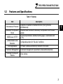
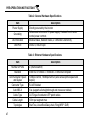
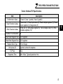
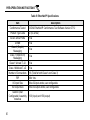
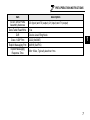
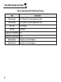
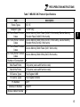
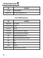
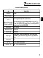
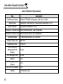
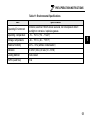
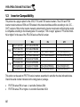
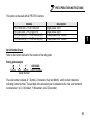

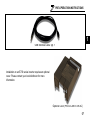
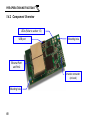
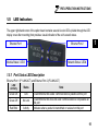
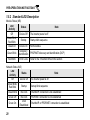
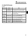
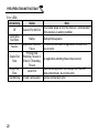
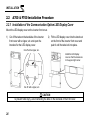
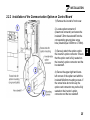

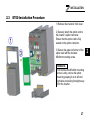
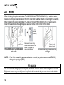
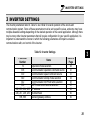
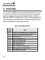
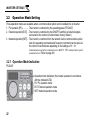
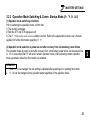
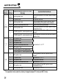

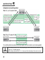
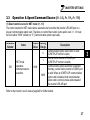
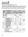
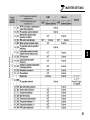
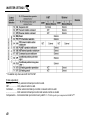
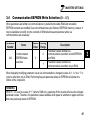

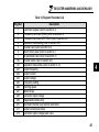
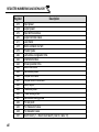

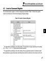
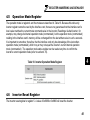
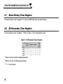
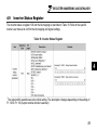
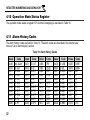
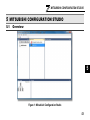


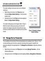
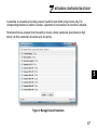

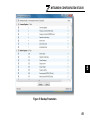
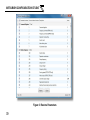

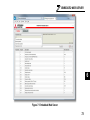
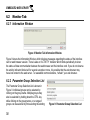

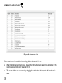
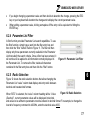

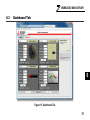
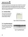


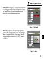
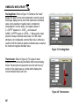
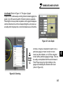


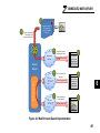
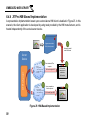
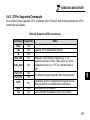


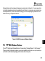
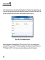


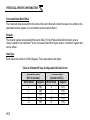
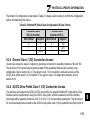
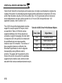
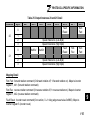
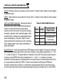
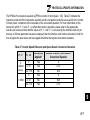
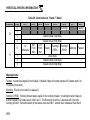


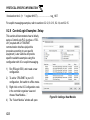
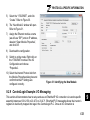
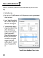
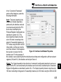
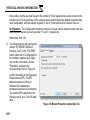
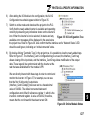
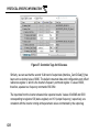
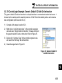
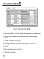
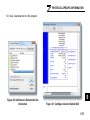
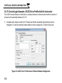
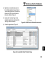
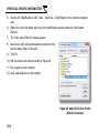
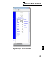
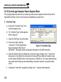
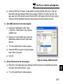
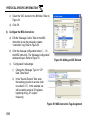
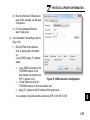
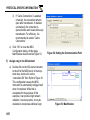
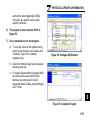
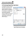
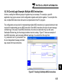
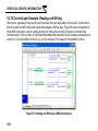
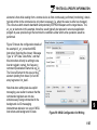

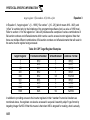
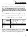

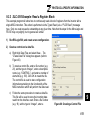
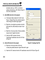
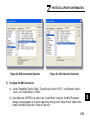
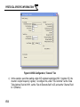
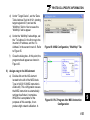
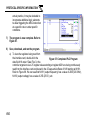
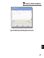
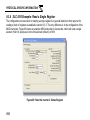
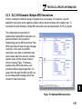
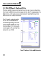
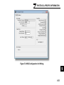
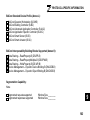

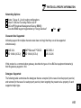
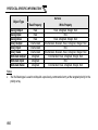
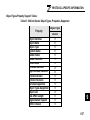
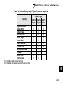
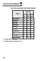
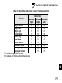
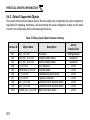
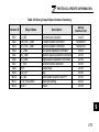


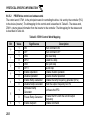
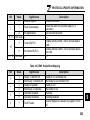
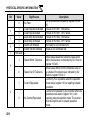
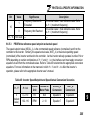
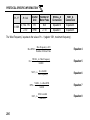

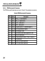
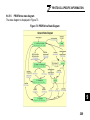
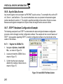
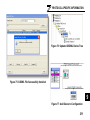
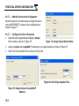
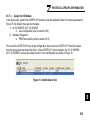
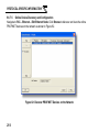
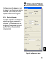

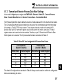

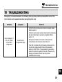
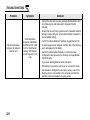
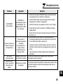
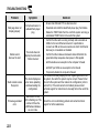
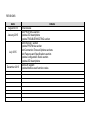


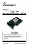


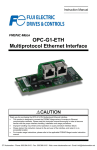


![XML.com: What is XSLT? [Aug. 16, 2000]](http://vs1.manualzilla.com/store/data/005688833_1-662f9c116837a2419b5ce07c9a17685b-150x150.png)