1
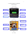
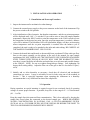
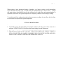
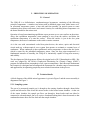
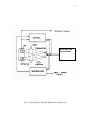
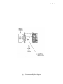
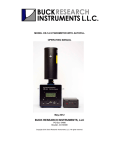
MODEL UHQ-4P HYGROMETER
OPERATING MANUAL
July 2014
(S/N >003)
BUCK RESEARCH INSTRUMENTS, LLC
PO Box 19498
Boulder, CO 80308
Copyright 2004-2014. Buck Research Instruments, LLC All rights reserved.
- 2 -
TABLE OF CONTENTS
1. Introduction .................................................................................................................. 4
1.1 General Description ....................................................................................... 4
1.2 Specifications ................................................................................................. 5
2. Location of Principal Components .............................................................................. 6
2.1 Main Unit ....................................................................................................... 6
3. Installation and Operation ...........................................................................................
3.1 Installation and Power-up Procedure .............................................................
3.2 Operation ........................................................................................................
3.3 Power-down Procedure ..................................................................................
8
8
8
9
4. Signal Processing ....................................................................................................... 10
4.1 Data Signals ................................................................................................. 10
4.2 Data Reduction Equations ............................................................................ 10
5. Principles of Operation ..............................................................................................
5.1 General .........................................................................................................
5.2 Technical details ...........................................................................................
5.2.1 Sampling System ...........................................................................
5.2.2 Mirror Module ...............................................................................
5.2.3 Optics Module ...............................................................................
5.2.4 Cooling System .............................................................................
5.2.5 Temperature Readout .....................................................................
11
11
11
11
14
14
14
14
6. Measurement Limitations ........................................................................................... 15
7. Maintenance and Troubleshooting .............................................................................
7.1 Sample line Cleaning ...................................................................................
7.2 Mirror Cleaning ............................................................................................
7.3 Leak Testing .................................................................................................
7.4 Troubleshooting Guide ..................................................................................
16
16
16
17
18
Appendix 1: Humidity Conversion Equations ................................................................ 19
Appendix 2: Connector Pin Assignments ....................................................................... 21
Appendix 3: Warranty ..................................................................................................... 22
Appendix 4: Instructions for using the CR-4 with sampling pump……………………...23
- 3 -
FIGURES
Fig. 1. Main unit ............................................................................................................................ 4
Fig. 2. Block diagram, UHQ-4P chilled mirror hygrometer ....................................................... 12
Fig. 3. Sensor assembly block diagram ....................................................................................... 13
- 4 MODEL UHQ-4P HYGROMETER OPERATING MANUAL
1. INTRODUCTION
The UHQ-4P is a chilled mirror hygrometer with a heated sample chamber that is set for 160° C.
This allows the instrument to read dew points from 40°C up to 100°C at a minimum pressure of
1013.25 mb (14.7 psia) and up to 150°C at 5000 mb . Dew points at lower pressures can be
measured but are limited by the boiling point of water at that pressure. The UHQ-4P uses a heat
sink and fan to cool a mirror pin to approximately 70°C below the sample chamber temperature
of 160° C. The UHQ-4P is designed to measure humidity in air and most non-corrosive gases at
pressures ranging from near vacuum to up to 100 psia.
1.1 General Description
The UHQ-4P is a chilled mirror, condensation type hygrometer. It achieves its high performance
by heating and cooling a mirror, using a heater wire and heat sink and fan assembly, and holding
the mirror at the dew or frost point by means of a servo control system. An IR LED and optical
detectors are used for sensing condensate on a mirror, and an ultra-stable temperature sensor
imbedded in the mirror is used to determine mirror temperature--the dew point. Since operation
of the UHQ-4P is based on a fundamental property of water vapor (dew point), it is intrinsically
capable of long-term accuracy and stability, without the need for periodic recalibration.
The UHQ-4P features an autobalancing function that automatically adjusts for mirror
contamination. To keep a constant layer of dew or frost on the mirror, the reflectivity of the
mirror must be measured when the mirror is completely cleared of condensation and when it is
completely obscured by condensation. Once this is done, 20% of this span is calculated and set to
be the control point. This is achieved by heating the mirror to a high enough temperature to
remove condensation, then turning on and off the LED that shines on the mirror. If
contamination ever gets to be enough that the control point cannot be achieved, another balance
function will be initiated and the control point reset. Once the contamination becomes too great,
an LED is illuminated to indicate that the mirror needs to be cleaned.
The UHQ-4P is microcontroller-based. The microcontroller uses flash memory that is fieldprogrammable and updateable. If this is required, please contact Buck Research Instruments,
LLC for instructions.
The components of the UHQ-4P are:
Main unit containing sensor assembly and display
Power cable and 24 VDC brick power supply
Data connector with pins
Operating manual
- 5 1.2 Specifications, Model UHQ-4P Chilled Mirror Hygrometer
Measurement range:
Dew point temperature:
Moisture concentration:
40oC to 150oC 1
3% to 100% at standard pressure
Dew point reading accuracy:
+ 0.2oC
Response time (10 degree step):
Less than 20 sec typical2
Nominal operating range:
Ambient Temperature:
Relative Humidity:
-40 to +40oC
0 to 100% RH, non-condensing
Flow rate of sample:
0.05 – 0.5 liters/minute
Max pressure rating:
150 psia
Output signals:
Mirror temp and balance
0-10 V, 4-20 mA and RS-232
Construction
Aluminum and steel (case)
Nickel-plated Al and stainless steel(sensor assembly)
Input voltage
100-240 VAC, 50-60 Hz (brick supply)
24-28 VDC (without brick supply)
Power consumption (typical)
< 45 watts
Dimensions, inches and (cm):
8" (20) w x 10.5" (26) d x 8" (20) h
Approximate Weight:
8.8 lbs (4 kg)
1
Do not attempt to read dew points above ambient without heating sample lines and sample chamber. Please contact
Buck Research Instruments, LLC if you plan to do this. Lower dew point reading of 40oC assumes 25 oC ambient
and a sample chamber temperature of 110 oC .
2
Response time once initial dew layer acquired
Note: These are approximate specifications. Exact performance will vary depending on installation and operating
environment.
- 6 2. LOCATION OF PRINCIPAL COMPONENTS
2.1 Main Unit (Figure 1)
Balance Switch
Display
Heat/Cool Switch
Power Switch
Rebalance LED
Service Mirror LED
Front
RS-232 Connector
& Signal Output, J2
Power Connector
Inlet to sample
chamber
Optics block and
cable
Outlet from sample
chamber
Back
Fig. 1. Main unit
- 7 -
A. BALANCE SWITCH (momentary). Depress for 5 seconds to initiate a balance cycle.
This will heat the mirror up to +110° C to clear off condensation and rebalance the optics
circuit.
B. HEAT/COOL SWITCH (momentary). Provides additional heat to partially clear the
mirror of condensate, or full cooling to allow additional dew to collect on the mirror.
C. REBALANCE LED. Lights during balance cycle. Also stays lit after balance cycle if
there is a small amount of contamination on the mirror.
D. DISPLAY. Backlit LCD display that displays sample chamber temperature, mirror
temperature (Mirror T or D/F Point when dew or frost point acquired), and balance (±
200 when dew point acquired).
E. POWER SWITCH
F. SERVICE MIRROR LED. Flashes when there is too much contamination on mirror.
Mirror must be cleaned to restore normal operation of instrument.
G. OUTLET. Connect heated tubing here. If using a piece of unheated tubing for a vent,
make certain that it is not stainless steel but Teflon or a similar plastic. Stainless
steel tubing that is not heated will draw significant amounts of heat away from the
sample chamber and could cause cold spots and false low readings.
H. OPTICS BLOCK AND CABLE. Contains LED and detector that looks at mirror through
lens.
I. POWER CONNECTOR. Connect included power supply to this connector.
J. RS-232. Connect to data acquisition system or PC running Hyperterminal .
K. INLET. Connect heated tubing to inlet.
L. SIGNAL OUTPUT 0-10 V and 4-20 mA outputs for various signals. See section 4.
- 8 -
3. INSTALLATION AND OPERATION
3.1 Installation and Power-up Procedure
1. Inspect the instrument for mechanical or other damage.
2. Connect the external power supply to the power connector on the back of the instrument. Flip
the power switch to the ON position.
3. After initialization of the electronics, the chamber temperature and the set point temperature
will be displayed until +160 ° C is reached. If you want to raise or lower the sample chamber
temperature, depress the HEAT switch to raise the temperature or the COOL switch to lower
the temperature to the desired set point. Once the set point temperature is reached, a balance
cycle will be initiated. The Rebalance LED will light and the display will show an increasing
mirror temperature until the set point temperature is reached. Once the balance cycle is
completed, the unit is ready to be attached to the inlet and outlet tubing. BE CAREFUL AS
THE SAMPLE CHAMBER IS HOT. USE GLOVES.
4. Connect the heated inlet and heated or downwardly-bent, non-heated Teflon outlet gas flow
lines to the sensor assembly see the photos at the end of the manual for some sample
installations. DO NOT UNDER ANY CIRCUMSTANCES USE UNHEATED STAINLESS
STEEL TUBING WITH THE HQ-4P OR YOU WILL VOID THE WARRANTY!!! Make
sure there is some flexibility in both inlet and outlet lines to avoid stress and possible damage
to the UHQ-4P. NOTE: do not over tighten Swagelok-type fittings. Over tightening can
destroy their sealing ability. Adjust the flow rate of the gas so that it is less than 0.5 lpm (1
scf/h).
5. Initially and as often thereafter as necessary, check that all electrical and mechanical
connections are secure. It may be advisable to test for leaks using one of the methods in
Section 7. This is especially important when operating the instrument in a humidity
environment that is very different from that of the sampled air.
3.2 Operation
During operation, no special attention is required except for an occasional check of operating
voltages to assure proper function. If possible, keep flow in the range 0.05 – 0.5 liters/minute
(0.1 – 1 scf/h).
Keep the sample line inlet protected from contamination. This is best achieved by keeping the
sample line closed when not connected to the desired sample gas. WHEN MEASURING
WATER CONCENTRATION IN NATURAL GAS, A GLYCOL-ABSORBING FILTER,
SUCH AS AN A+ GLYSORB FILTER, MUST BE INSTALLED BEFORE THE INLET TO
THE CR-4 OR ERRONEOUS READINGS WILL RESULT.
- 9 -
When making a large downward change in humidity, it is better to make several intermediate
steps rather than one large step, to avoid losing the condensation layer on the mirror. At high
dew point values, always allow time for the moisture levels in the lines and sensing chamber to
equilibrate, and for the D/F point temperature to completely stabilize before taking a reading.
To avoid internal line condensation and resultant erroneous readings, do not allow the inlet lines
to cool below the expected dew point temperature.
3.3 Power-down Procedure
.
1. If possible, purge the inlet tubing and sample chamber with dry gas such as room air or
nitrogen. USING GLOVES, Disconnect the heated tubing from the instrument.
2. Flip the Power Switch to OFF. DO NOT TURN THE POWER OFF WHILE TUBING IS
STILL CONNECTED OR SAMPLE CHAMBER WILL FILL WITH WATER AND WILL
NEED TO BE CLEANED AND MAY BE DAMAGED AS WELL.
- 10 4. SIGNAL PROCESSING
4.1 Data Signals
The following analog signals are available at signal connector J2, and vary over the following
ranges:
VDF
BAL
VAMB
SVC MIRROR
HTR FAILURE
Mirror temperature (Dew/frost point), 0-10v and 4-20 mA
Balance voltage, 0-10v
Chamber temperature, 0-10v
0 = mirror OK, 5V = mirror needs cleaning
0 = heater OK, 5V = heater failure
4.2 Data Reduction Equations
VDF: Dew/frost point temperature is determined from VDF by:
Tdf = [20 x VDF(v)].
Tdf = [ 8 x VDF(ma)].
(0-10V)
(4-20 mA)
(1)
(2)
VAMB: Chamber temperature is determined from VAMB by:
Tchamber = [20 x VDF(v)].
(0-10V)
(3)
Conversion to Other Humidity Units To convert dew/frost point readings to other humidity
units, refer to Appendix 1.
Pressure Correction: Dew/frost point temperature (or humidity in any other units) may be
corrected for variations in chamber pressure as follows:
1. Convert dew/frost point reading to vapor pressure e.
2. Calculate corrected vapor pressure ec, according to
ec = e x pa/pc,
where pa = ambient (static) pressure, and
pc = chamber pressure.
3. Convert ec back to dew/frost point temperature, or to other units as needed.
(4)
- 11 -
5. PRINCIPLES OF OPERATION
5.1 General
The UHQ-4P is a chilled-mirror, condensation-type hygrometer, consisting of the following
principle components: a stainless steel mirror with an attached copper stem with a heater on it,
an associated temperature sensor, a heat sink and fan assembly, an optical system to sense
condensing dew (mirror reflectance) and control circuitry for controlling mirror temperature via
the heater attached to the mirror stem.
Operation is based on maintaining equilibrium vapor pressure over a water surface on the mirror.
Above the equilibrium temperature, mass transport is away from the surface, and below the
equilibrium temperature it is onto the surface. When the surface is just at the dew point
temperature, the mass of condensate on the surface remains constant.
As is the case with conventional cooled dew-point devices, the mirror, optics and electrical
circuit make up a thermo-optical servo system that operates to maintain a constant layer of
condensate. When condensate is thus equilibrated, mirror temperature is then at the dew point,
which is sensed by the imbedded temperature sensor. Since the dew point temperature is a
fundamental measure of humidity, the UHQ-4P is intrinsically capable of long-term accuracy
and stability.
The development of this hygrometer follows the original work of H.J. Mastenbrook at NRL. His
work was adapted by the NOAA Geophysical Monitoring for Climatic Change (GMCC)
program for balloon-borne stratospheric water vapor measurements. Buck Research Instruments
has extensively redesigned and reconfigured the instrument for a broader range of measurements
and applications, incorporating proprietary new technical innovations in the process.
5.2 Technical details
A block diagram of the chilled mirror hygrometer is given in Figure 2 and the sensor assembly is
diagrammed in Figure 3.
5.2.1 Sampling system
The gas to be measured (sample gas) is brought to the sensing chamber through a heated inlet
system and allowed to flow across the mirror surface in the heated sensor chamber. At the exit
of the sensor chamber, the sample gas flows out through a heated outlet and can either be
connected to a heated sample line or to a piece of unheated tubing that is bent downward so that
condensed moisture does not flow back into the sample chamber.
- 12 -
Heat sink and
fan assembly
Fig. 2. Block diagram, UHQ-4P chilled mirror hygrometer
- 13 -
Fig. 3. Sensor assembly block diagram
- 14 The sampling system must be carefully sealed to prevent room air from contaminating the
measurements.
5.2.2 Mirror Module
The mirror assembly consists of a mirror, a mirror stem with a heater wire wrapped around it, a
temperature sensor, a heat sink and a fan. A small, ultra-stable temperature sensor is installed in
the mirror face to measure the dew point temperature. Heating is accomplished using the heater
wire and cooling is provided by the heat sink and fan.
5.2.3 Optics Module
The mirror surface is maintained continuously and automatically at the dew point temperature by
an electro-optical control system. This system measures the quantity of light specularly reflected
from the mirror condensate and maintains a constant reflectance at the mirror surface, thus
providing the condensate equilibrium for the frost-point temperature.
The optics module consists of a photodiode pair and a light emitting diode (LED). One
photodiode maintains constant LED intensity; the other photodiode provides a current output that
is proportional to the light reflected from the mirror. The bias circuit is set so that when the
proper condensation layer is on the mirror, about 80% of the light emitted by the LED is received
at the detector.
5.2.4 Cooling System
The mirror stem is thermally coupled to the heat sink by a thermally conductive coupling. In
operation, heat is pumped away from the mirror stem by the heat sink and fan.
5.2.5 Temperature Readout
For obtaining the dew or frost point temperature from the temperature senor, three readouts are
provided: VDF signal voltage, RS-232 output and a direct temperature indication on the display.
Both are accurate within 0.1 oC throughout the measurement range.
- 15 6. MEASUREMENT LIMITATIONS
Under field operations, measurement errors can arise from a number of causes. Any deviation of
the mirror temperature from the dew point temperature will of course cause error.
Perhaps the most common error source is from outside air leaking into the hygrometer sampling
system. Therefore, it is important that the instrument be leak tested periodically, and with each
relocation of the instrument, especially if components of the instrument have been exchanged or
serviced.
Long exposure of the sampling system to high humidities, or condensation of water (which
occurs if cold surfaces are exposed to air which has a higher dew point than the temperature of
the surfaces) causes temporarily high readings until the walls have completely outgassed. IT IS
ESSENTIAL THAT HEATED TUBING IS USED WITH THE UHQ-4P AND THAT THE
TUBING AND THE UHQ-4P’S SAMPLE CHAMBER HAS HEATED TO 160 oC BEFORE
ANY HIGH HUMIDITY AIR IS FLOWED THROUGH THE TUBING OR THE UHQ-4P. The
lines may take a very long time to dry enough to allow accurate readings if this is not done. Any
hygroscopic material in the lines or chamber, such as dust, further lengthens this time. It is
therefore advised to keep the lines clean and dry.
Calibration of the mirror temperature sensor and associated electronics is required to accurately
determine dew/frost point temperature. Buck Research Instruments has done this. Once
calibrated, the temperature sensor has been found to exhibit no measurable drift, even after years
of use. Low drift components are used throughout the temperature sensing circuit to ensure
long-term accuracy. However, recertification and recalibration is recommended yearly to ensure
proper operation.
Errors can arise from failure to correct for differences between chamber pressure and ambient
values. This is only important if you are measuring ambient dew/frost point and not H2O
concentration.
The system must be allowed to fully equilibrate before accurate readings can be obtained. When
measuring very low frost points, equilibration can take much longer.
Within twenty degrees below freezing, the existence of supercooled water on the mirror can
cause the temperature to read low, as the instrument is measuring dew point. Eventually the dew
will turn to frost. To speed this up, press the COOL switch and allow the mirror to cool 5-10
degrees below the dew point reading, then release COOL switch. This will convert the dew to
frost, as long as the mirror temperature does not go above 0° C after COOL switch is released
Contamination of the mirror by salt or other electrolytes can vary the relationship between
vapor pressure and dew/frost point (Raoult error). Other chemical contamination may
cause similar error. This is particularly relevant when measuring in natural gas, as glycols
contained within it can condense out on the mirror. This is why a glycol-absorbing filter
must be used when measuring natural gas.
- 16 7. MAINTENANCE AND TROUBLESHOOTING
The following maintenance items should receive attention as required:
1. Cleaning of sample lines, depending on use (Sect. 7.1).
3. Mirror check and cleaning (Sect. 7.2).
4. Leak checking (Sect. 7.3)
7.1 Sample line Cleaning
To keep sample lines clean, thus improving response at very low humidities, wash with water or
acetone and blow dry with a mild pressure from a dry air or nitrogen source. It may be desirable
to heat the lines for a few moments to drive off residual water.
7.2 Mirror cleaning
The mirror should be cleaned when the Check Mirror LED is flashing.
1. Make certain mirror is at or near the room temperature and power has been shut off.
There are 2 holes in the flat part of the optics block. Insert hex ball driver into holes and
loosen each screw. The screws will remain captive inside. Once screws are loose, remove
optics block. It will be held by the cable coming out of it, which is not removable. The
mirror is now exposed and can be cleaned.
2. Moisten a soft cotton swab with mirror cleaning fluid (acetone) and gently wipe the swab
over the mirror surface. Immediately dry the surface with fresh cotton swab. Inspection
with flashlight may be helpful.
3. If necessary, repeat process. If contamination persists, clean again with acetone, followed
by water, using a small amount. Never use alcohol in the sensing chamber, as this affects
the hygroscopic properties of the mirror surface for some period of time. (In the absence
of acetone, distilled water alone or used after acetone or MEK can be effective.)
CAUTION: The mirror surface has a coating that scratches easily. However,
moderate scratching does not prevent normal operation. Use only soft flexible
cotton swabs to clean the mirror. Apply minimal pressure
4. Turn instrument power on and wait and see if Service Mirror LED and Rebalance LEDs
turn off. If either or both LEDs stay lit, try cleaning the mirror again. Make sure the
mirror is completely dry before turning power on.
- 17 -
5. If the Service Mirror LED cannot be turned off by cleaning the mirror, remove the optics
block and clean the lens and entire sample chamber.
7.3 Leak Testing
The introduction of even small amounts of room air into the sampling system will cause errors in
high dew point readings. Therefore, it is desirable that leak testing be performed on the
instrument package and sampling system after initial assembly, and after any maintenance
activity that involves disassembly of the instrument or interconnecting tubing.
Method 1. Connect a vacuum pump and vacuum gauge to the sampling system inlet port, and
close or cap the outlet port (or vice versa). Evacuate down to the minimum attainable pressure.
A reading of 100 microns Hg or less indicates the system is adequately sealed.
To locate a leak, place a few drops of alcohol on each tubing connection and watch the vacuum
gauge pressure reading. If the reading abruptly increases, there is a leak. Allow some time for
the vacuum readings to recover after each upscale deflection before proceeding to the next
connection.
Method 2. If the vacuum pumping system is unable to evacuate the inlet plumbing to a level that
will produce an on-scale reading on the vacuum gauge, disconnect the vacuum pump from the
gas inlet port and replace it with a low-pressure air supply with a needle valve for regulation.
Slowly pressurize the gas inlet tubing, being careful to limit the pressure applied to no more than
two atmospheres. Dampen the inlet tubing connections with soap solution or other leak
detection solution, and watch for air bubbles forming at each connection. The presence of any
air bubbles indicates a leak at the connection. Repair any connections found leaking and recheck
for leaks. When no more bubbles can be found, disconnect the low-pressure air supply and
reconnect the vacuum pumping system. Repeat the preceding vacuum leak testing procedure.
CAUTION: Overpressure within the above limits will not damage the pressure
sensor. However, slight calibration adjustments may be necessary after any
overpressure. Overpressure limit: 100% of span.
Method 3. Plug one end of the sensing chamber. Attach an ordinary pump with a shutoff valve
to the other end. Lower the pressure as much as possible. Close the shutoff valve and monitor
pressure inside the sensing chamber to determine leak rate. With proper sealing, the pressure
change rate should be less than 0.2 % of pressure differential per minute. Leaks can then be
located by overpressuring the instrument as in Method 2.
- 18 -
7.4 Troubleshooting Guide
Display shows Mirror needs cleaning. Service Mirror LED blinking:
1. Mirror needs cleaning. Clean mirror
2. Optics cable is disconnected. Reconnect optics cable.
Rebalance LED stays lit after balance cycle finishes:
1. Mirror starting to get contaminated. CR-4 will continue to function normally, but be
prepared to clean mirror soon.
Oscillation of output (some oscillation at dew point above 0 oC is normal):
1. Reduce sample flow until oscillation stops, then gradually increase flow again.
2. Turn instrument off, allow to cool, and clean mirror.
- 19 APPENDIX 1: HUMIDITY CONVERSION EQUATIONS
(Revised 7/96)
Computer-efficient algorithms for converting among several humidity units, as used in HCON, are
given here. They utilize vapor pressure formulations developed by A. Buck (1981).
DP
e
es
P
r
RH
rho
rhos
T
Tk
= dew or frost point in deg C
= vapor pressure in millibars
= saturation vapor pressure in millibars
= pressure in millibars
= mixing ratio by weight in ppm
= relative humidity in percent
= absolute humidity in g/m3
= absolute humidity at saturation
= temperature in deg C
= absolute temperature in K
Saturation vapor pressure (es) = f1(T) = e/RH
Dew/frost point (DP) = f2(e)
= f2[r x P/(622 x 103 + r]
= f2(RH x f1(T)/100)
= f2(rho x Tk/216.7)
(e)
(r)
(RH)
(rho)
Vapor pressure (e)
= f1(DP)
= r x P/(622 x 103 + r)
= RH x f1(T)/100
= rho x Tk/216.7
(DP)
(r)
(RH)
(rho)
Mixing ratio (r), ppmw = (18.02/ M.W. of gas) x 106 x e/(P-e)
= (18.02/ M.W. of gas) x 106 x f1(DP)/[P - f1(DP)]
= (18.02/ M.W. of gas) x 106x RH x es/(100 x P - RH x es)
= (18.02/ M.W. of gas) x 106 x rho x Tk/(216.7 x P - rho x Tk)
(e)
(DP)
(RH)
(rho)
Relative humidity (RH) = 100 x f1(DP)/f1(T)
= 100 x e/es
= 100 x r x P/[(622x103 + r) x es]
= 100 x rho x Tk/(216.7 x es)
(DP)
(e)
(r)
(rho)
Absolute humidity (rho)= 216.7 x f1(DP)/Tk
= 216.7 x e/Tk
= 0.2167 x r x P/[(622 + .001 x r) x Tk]
= 216.7 x RH x es/(100 x Tk)
(DP)
(e)
(r)
(RH)
mixing ratio by volume (ppmv) = mixing ratio by weight (ppmw) x (M.W. of gas)/ 18.02
grains/lb = r x 0.007
Precipitable cm per km = rho/10
- 20 -
NOTE 1: f1(DP) and f2(e) are variations on vapor pressure formulations found in Buck, A: J Appl
Met 20, pp 1527-1532 (1981). They are given by:
e vs. DP or es vs. T:
f1(DP) = EF x aw x exp [(bw - DP/dw) x DP/(DP + cw)] (over water)
= EF x ai x exp [(bi - DP/di) x DP/(DP + ci)] (over ice)
DP vs. e or T vs. es:
f2(e) = dw/2 x [bw - s - ((bw - s)2 - 4 cw x s/dw)1/2]
= di/2 x [bi - s - ((bi - s)2 - 4 ci x s/di)1/2]
(over water)
(over ice)
where:
aw = 6.1121
bw = 18.678
cw = 257.14
dw = 234.5
ai = 6.1115
bi = 23.036
ci = 279.82
di = 333.7
s = ln (e/EF) - ln (aw or ai)
2
EFw = 1 + 10-4 [7.2 + P (0.0320 + 5.9 x 10⁻⁶ T )],
2
EFi = 1 + 10-4 [2.2 + P (0.0383 + 6.4 x 10⁻⁶ T )],
where P is in millibars and T is in oC.
NOTE 2: RH is defined here using es with respect to ice below freezing. However, RH is also
frequently defined using es with respect to water, even below freezing.
NOTE 3: These conversions are intended for use with moist air rather than pure water vapor. They
therefore include EF, the enhancement factor, which corrects for the slight departure of the behavior
of water in air from that of a pure gas.
NOTE 4: The definitions f1 and f2 for ice agree with an extrapolation of NBS values down to -120
deg C, within 0.5%.
- 21 -
APPENDIX 2: CONNECTOR PIN ASSIGNMENTS
J2 16-pin Signal connector
Pin
1
2
3
4
5
6
7
8
9
10
11
12
13
14
15
16
Chamber Temp (0-10 V)
Chamber Temp Return
Balance (0-10V)
Balance Return
Heater Failure (0-5V)
Heater Failure Return
Service Mirror (0-5V)
Service Mirror Return
VDF (0-10V)
VDF Return
VDF (4-20 mA)
+24 VDC
Not used
Not used
Not used
Not used
J4 RS-232 connector
9600 Baud, 8-N-1. Flow control set to NONE. Use null modem cable with
Female/Female ends.(Included)
Pin
2
3
5
Rx
Tx
Ground
- 22 -
APPENDIX 3:WARRANTY
Manufacturer warrants that the items delivered shall be free from defects (latent and
patent) in material and workmanship for a period of one year after acceptance of the
specific goods by Buyer. The Buyer’s sole and exclusive remedy under this warranty
shall be limited to repair or replacement. Defective goods must be returned to the
Manufacturer promptly after the discovery of any defect within the above referenced oneyear period. Transportation expenses to return unit to Manufacturer shall be borne by the
Buyer. Return shipping to Buyer shall be borne by Manufacturer for valid warranty
claims. This warranty shall become inapplicable in instances where the items have been
misused or otherwise subjected to negligence by the Buyer
NOTWITHSTANDING ANY OTHER PROVISION OF THIS CONTRACT, NO
OTHER WARRANTIES WHETHER STATUTORY OR ARISING BY OPERATION
OF LAW, EXPRESSED OR IMPLIED, INCLUDING BUT NOT LIMITED TO THOSE
OF MERCHANTABILITY OR FITNESS FOR PARTICULAR PURPOSE, SHALL
APPLY TO THE GOODS OR SERVICES PROVIDED HEREUNDER, OTHER THAN
THE REPAIR AND REPLACEMENT WARRANTY ABOVE . SELLER SHALL IN
NO EVENT BE LIABLE TO BUYER OR ANY THIRD PARTY FOR ANY DAMAGE,
INJURY OR LOSS, INCLUDING LOSS OF USE OR ANY DIRECT OR INDIRECT
INCEDENTAL OR CONSEQUENTIAL DAMAGES OF ANY KIND.
- 23 -
RS-232 output stream when display is switched off (optional)
159.20,119.05,0, 248,116,0, 25.00,05/20/04 13:42:53
159.20,118.96,0, 223,110,0, 25.00,05/20/04 13:42:55
159.34,119.11,0, 223,102,0, 25.00,05/20/04 13:42:56
temp, chamber temp, status, balance, PWM, mirror, board_temp, date, time
Where
temp : mirror temperature in degrees C
chamber temp: sample chamber temperature in degrees C
status : 0 = mirror temperature, 1 = dew/frost point, 2 = balance routine
balance : within + or – 300 counts of zero indicates dew or frost point
PWM : 0 to 255, indicates how much power is applied to heater
Mirror : 0 = clean mirror, 1 = mirror contaminated, should be cleaned soon
Board_temp : temperature of main PCB
Date : date in months/days/years
Time : time in 24 hours: minutes : seconds