1
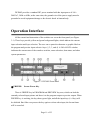
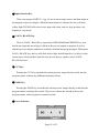
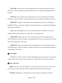
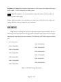
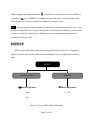
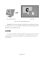
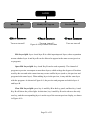
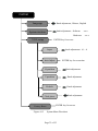
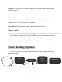
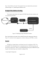
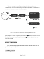
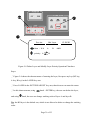
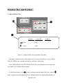
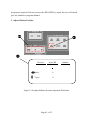
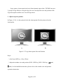
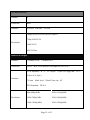
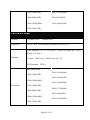
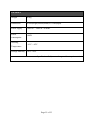
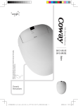
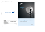
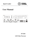
SHENZHEN SPEEDLEADER TECHNOLOGY User Manual DVX402 Seamless Switch About the Manual Without the written permission of the company, it is forbidden for any company or individual to imitate, copy, or transcribe part or all of the contents of the manual. It is not allowed to have the commodity publicity or achieve any commercial or profit-seeking purpose in any form (electronic form, mechanical form, photocopying form, recording form, or other possible ways). Please carefully read this manual before using this equipment. All the product specifications and information mentioned in the manual are only for reference. If there is the content updating, the company will not make further notice. Unless there is a special agreement, this manual is only taken as an instruction, and all statements and information will not constitute a guarantee of any kind. Brand Royalty VGA and XGA are the registered trademarks of IBM Corporation. VESA is a trademark of the Video Electronics Standards Association. The logo of HDMI and High-Definition Multimedia Interface are the trademark of HDMI Licensing LLC. Safety Instructions This symbol prompts the user that there are the important operation and maintenance instructions in the user manual. Page 1 of 55 This symbol warns the user that there is the hazardous voltage exposed inside the equipment and there is an electric shock hazard. This equipment must be connected with ground wire. This equipment needs a rated power voltage. Ensure that the input voltage error should be between - 10% and +10%. Do not connect AC power cord with another AC power cord which may lead to excessive noise. Please use the equipment when the surrounding temperature is from -10 ℃ to 45 ℃, and the relative humidity is 90% or less than that. Do not use this equipment in certain special circumstances, such as, closing to a heat source, which may cause overheating of the equipment and damage it. Please use it in a well-ventilated place and pay attention not to block the equipment vents. Do not expose this equipment in the place which has the possibility for accidental collision or vibration, and reinforcement processing is necessary in the vibration place. When you use the equipment, please make sure that there are no objects, such as water and metal objects, inside the equipment. Otherwise, it will damage the equipment and cause a fire. If there is any irregularity or abnormality for the equipment, please immediately turn off the power supply, disconnect the AC power cord, and see “Trouble Clearing”. If this equipment is damaged, do not disassemble it. Please contact our maintenance service department. Page 2 of 55 Contents Overview ....................................................................................................................... 5 Application .................................................................................................................... 6 Installation .................................................................................................................... 7 Install DVX402 ..................................................................................................... 7 Rear Panel............................................................................................................. 8 Operation Interface ...................................................................................................... 11 Menu System ................................................................................................................ 15 Menu System Overview ...................................................................................... 15 Main Menu System ............................................................................................. 17 Automatic Menu ................................................................................................. 18 Input Menu ......................................................................................................... 19 Output Menu....................................................................................................... 21 Special Effects Menu…………………..………………………………...………...22 Layer Menu ........................................................................................................ 24 Logo Menu ......................................................................................................... 29 Preview Menu ..................................................................................................... 30 System Menu ...................................................................................................... 31 Operation .................................................................................................................... 33 Factory Reset Operation ...................................................................................... 33 Output Resolution setting .................................................................................... 34 Signal Input ........................................................................................................ 34 Switch ................................................................................................................ 36 Set Fade Time and Preview Switching Mode........................................................ 36 Layer Operation .................................................................................................. 37 AddingLayer………………………………………………………………………37 DeleteLayer……………………………………………………………… ………38 Layer Priority…………………………………………………………………….. 38 Window Size and Position …………………………………………………………38 Crop Size and Position of Picture ……………………………………….….…38 Page 3 of 55 Contrast………………………………………………………………………………......44 Save and Recall of the Preset ............................................................................... 45 Transfer of the Preset………………………………………………………..….…46 Logo capture and Transfer………………………………………………………..47 Logo or Black Field Transfer…………………………………………………..….50 Specifications…………………………………………………………………………....52 Page 4 of 55 Overview DVX402 integrates 4 channel independent image processing engine, which can perfectly achieve seamless switching and high-definition image analysis conversion. It has the function of preview edition, program output, switching transition, LOGO capture and insertion and screen freezing, which can also realize variety of advanced functions required in a high-end presentation environment. DVX402 has a 4-channel fully configurable input, which can access 16 channels of video input, including 4-channel DVI, 4-channel VGA, 4-channel VID and 4-channel 3G-SDI (optional), and each channel can receive SD or HD video signals. DVX402 has 2-channel output, the main channel of which is the live program output, and the vice channel of which is preview output. Program and preview output interface has two DVI and one VGA, with the highest resolution up to 1920 x 1200 @ 60Hz or 2048 x 1152 @ 60Hz. More Operating Layers: DVX402 has four layers, and a single output channel can output three layers at most. Each layer has an independent parameter setting, and the user can edit the position, size, color, LOGO of each layer. It has real-time save function that means it can restore the state before shutdown automatically after power failure. Perfect Seamless Transitions Effects: DVX402 is built-in high-performance image resolution converter, which can receive more-channel video signal, including 4-channel 3G-SDI signal (optional), and can have fade switch among any signal source. The switching time can be adjusted from 0 to 5 seconds. DVX402 has rich controllable functions, which is very suitable for the company conference room, auditorium, church or other on-site activities. All the settings and operations can be done by the front keys and RS-232/IP Link. Page 5 of 55 Application Figure 1-1 shows a typical application of DVX402. DVX402 receives a variety of signal and resolution input, supporting the video input from the low resolution to high resolution as follows: VGA (XGA, WUXGA) DVI (Compatible HDMI 1.3) Composite Video (NTSC, PAL, SECAM) SD/HD/3G-SDI video (optional) Figure 1-1 Application of DVX402 Page 6 of 55 DVX402 has rich input and output interfaces, which can switch in VGA and DVI signal of desktop computer, laptop, SDI (optional) signal of high-definition camera, and DV and DVD video signal. Both the outputs of preview and program have two DVI interface and a VGA interface, which can meet the various needs of users. DVX402 has two-channel outputs, one channel can be connected to preview display; and the other channel can be connected to the projector or LED video wall. After editing images after the preview display, the user can follow the switch or exchange the switch to the video wall. If the user needs to connect the LED video wall, it can be connected to LED video processor, and then output it to the LED video wall. Program output of DVX402 can also be connected to the LED video processor or LED video splicing processor, and the switch does not need to zoom the image and the DVI output of the program is directly connected to the video processor. If necessary, the user can use the software or the console to have full control on DVX402. Installation Install DVX402 The user can choose whether to install DVX402 to rack or flight case. DVX402 is a standard 2U chassis, with the size of 8.8cm (Height) x 44cm (Width) x 33.5CM (Depth). While installing, please avoid scratching the case and use cushion for fixing suspension loop. Page 7 of 55 Figure 2-1 Install DVX402 Rear Panel Figure 2-2 Connection Terminals of DVX402 Rear Panel ① # 1 ~ # 4 Channel Video Input It can receive a 4-channel video at the same time, and each channel can receive VGA, DVI, HDMI (DVI terminal), VID (CVBS) and SDI (optional). DVX402 offers a number Page 8 of 55 of input interfaces which can connect 16-channel video. After a one-time access, the user can quickly switch video source without reconnection. The following are the corresponding terminals for the input interfaces: DVI input - DVI-D VGA input - DB15 SDI input (optional) - BNC VID input - BNC Figure 2-3 DVX402 Channel # 1 Input Interface ②③ Communication Interface ② TCP / IP interface, using RJ-45 terminal, is reserved for the communication interface. ③ RS-232 interface, using DB9 terminal if it is connected by computer’s RS-232 or console, resolution adjustment, channel selection and seamless switch to DVX402 can be operated by it. ④ Preview Video Output Interface Preview output is normally connected to the preview display. There are two video output interface in the preview channel, and has two DVI-I seats, of which DVI / VGA interface can output DVI and VGA signal. When using VGA output, DVI-VGA adapter Page 9 of 55 need to be connected to the DVI / VGA interface. The video image and resolution outputted by the two interfaces are the same, which can be switched in multiple monitors; therefore, both the operator and the commander can see the switching picture. Figure 2-4 DVX402 Preview Output Interface ⑤ Program Video Output Interface The program output channel has two video output interface, using two DVI-I terminals, of which DVI / VGA interface can output DVI and VGA signal. When using VGA output, DVI-VGA adapter need to be connected to the DVI / VGA interface. The video image and resolution outputted by the two interfaces are the same. Normally, DVI is outputted to the LED sending card or projector. The interface output resolution can change by itself, with the resolution output up to 2048 x 1152. Figure 2-5 DVX402 Program Output Interface ⑥ ⑦ AC Power Connector and AC Switch Page 10 of 55 DVX402 provides a standard IEC power terminal with the input power of 100 ~ 240VAC, 50Hz or 60Hz, at the same time, the ground wire of the power supply must be grounded to avoid equipment damage or the electric shock to human body. Operation Interface All the control and instruction of the switcher are set on the front panel (see Figure 3-1). These keys provide yellow and green background lights, which indicate the current input selection and layer selection. The user can re-paste the character or graphic label on the program and preview input selective keys (1, 2, 3, and 4). A 240×64 LCD window indicates the current state of the seamless switcher, menu selection, data status, and other system parameters. Figure 3-1 DVX402 Front Panel ① FREEZE: Screen Freeze Key There is FREEZE key in PROGRAM and PREVIEW key area, which can lock the currently selected input picture and show it to the program output or preview output. When FREEZE key is working, the key shows green light, and all the input keys (1~4 key) will be shielded. But if the user presses the key again or selects other input, the frozen frame will be canceled. Page 11 of 55 ②Input Selection Key These two groups of INPUT # 1~ # 4 are to choose input source and then output to the program or preview display. When the input channel is selected, the key will show yellow light. DVX402 will record every input video data, such as, layer position, size, brightness, crop mode. ③ LOGO / BLACK Key There is LOGO / BLACK key separately in PROGRAM and PREVIEW key area, which can output the stored logo or black to the preview output or program. It is first edited in preview display and then it would be switched into program output. When press LOGO / BLACK key, the key will flash yellow light, and all input key (1to 4 key) in the current layer will be masked, until the user presses the key again to cancel LOGO / BLACK function. ④ CUT Key Pressing the CUT key can make the current preview image directly switch into the program output, without any additional transition effects. ⑤ FADE Key Pressing the FADE key can make the current preview image directly switch into the program output, realizing fade switch. The preview shows the smooth switch to the program output, achieving perfect seamless switch. ⑥ Layer Selection Page 12 of 55 Figure 3-2 DVX402 Front Panel: Layer Key Area There are three keys in LAYER key area, respectively BG key, A key and B key, with the corresponding switch BG layer, A layer and B layer. After selecting layer, signal switch, position adjustment, screen size adjustment and crop adjustment can be operated. BG layer is called background layer, located in the bottom, under the A layer and B layer, which cannot change the layer stacking order. A layer and B layer is called superimposed layer, indicating by MIXER, which can modify the layer stacking order, and can also set superimposed layer separation. About the operation of the layer, it will be described in detail in the following sections. ⑦ PICTURE ADJUST Key Pressing the key within the PICTURE ADJUST key area can change the parameters of the current layer. After choosing the layer and pressing the image property key in the PICTURE ADJUST key area, the user can adjust the parameters of the currently selected layer. Figure 3-3 PICTURE ADJUST Key Area Page 13 of 55 WIN SIZE: the layer size, after selecting the layer, the user should press the WIN SIZE key to enter the settings, and using knob, the user can adjust the pantograph ratio of the layer. WIN POS: layer position, after selecting the layer, the user should press the WIN POS key to enter the settings, and using knob, the user can adjust the position of the layer. BRI/CONT: brightness and contrast, after selecting the layer, the user should press the BRI/CONT key to enter the settings, and using knob, the user can adjust the brightness and contrast of the layer. Layer: after selecting the layer, the user should press the LAYER key to enter the settings, and can delete the layer or change the layer stacking order. CROP SIZE: image crop size, after selecting the layer, the user should press the CROP SIZE key to enter the settings, and using the knob, the user can adjust the horizontal and vertical total pixels of the layer. CROP POS: image crop position, after selecting the layer, the user should press the CROP POS key to enter the settings, and using the knob, the user can adjust the position of crop window of the image. ⑧ State Display DVX402 has a 240 x 64 LCD window indicating the current state of the switch, menu selection, data state and other system parameters, which will be described in detail next. ⑨ Menu Operation MENU-menu key: press the Menu key to enter the main menu system or return to the previous menu, whose function will be introduced in detail in the following parts. ENTER-confirming key: which means to enter a menu or confirm the operation. Page 14 of 55 ⑩ : horizontal adjustment knob; and : vertical adjustment knob: which can adjust menu options and parameters, or adjust the size and position of the layer. ⑪ USB interface The USB communications interface or provide 5VDC power supply to the USB device. Menu System Menu System Overview DVX402 has a convenient menu system; Figure 4-1 shows the default display menu of DVX402 after electrifying. The user can observe the corresponding source and other important information of the current preview and program layers. Page 15 of 55 Electrify Preview Speed Leader DVX402 BG:#1 <DVI 1920x1080/60> A :#2 <VGA 1024x768/60> B:#3 <DVI 1280x720/60> Program BG:#4 <DVI 1920x1080/60> A:#3 <DVI 1280x720/60> B:off Default Resolution MENU 1920x1080/60 Mix layer split System Main Menu on Preview switch swap Fade time 1.5 s Figure 4-1 System Menu Flowchart There are four keys to operate the menu and change the parameters, namely: MENU key: press this key to activate the main menu, and after entering the main menu, press the MENU key to return to upper step of the menu. ENTER key: it is confirmation key. By pressing the ENTER key, the user can enter to the sub-menu or change the operation. Page 16 of 55 Knob: horizontal knob, you can adjust the horizontal menu options by this key. When choosing the image adjustment key, the user can adjust parameters or the size and location of the layer. Knob: vertical knob, you can adjust the vertical menu options by this key. When choosing the image adjustment key, the user can adjust the size and location of the layer. NOTE:When the user presses the MENU key, ENTER key can work. NOTE: When the user enters to the sub-menu, the menu system will automatically return to the default menu cycle if there is no operation for 30 seconds. Main Menu System Press the MENU key in the default cycle, DVX402 will enter to the main menu system. Figure 4-2 is the first layer menu displayed on the LCD by main menu system. The first level sub-menu includes Auto, input, output, effect, logo, layer, preset and system. The user can enter quickly to the next level menu by ENTER key and knob. AUTO LAYER INPUT OUTPUT EFFECT LOGO PRESET SYSTE M Figure 4-2 Menu System Page 17 of 55 AUTO The function of DVX402 Automatic Menu is to classify and replace the user’s data and resume one or more users’ parameters to the factory default state. Figure 4-3 expands the sub-menu and parameters that can be set in AUTO Menu. The AUTO Menu restores all the user data related to the window size, window position, and crop size and interception position. AUTO Channel Knob adjustment Layer Knob adjustment Type Auto Knob adjustment ENTER Program, preview, program Background layer, A、 crop、window、 and preview B、A&B、all crop and window Figure 4-3 Auto Menu Flowchart Page 18 of 55 Channel: there are programs and previews in the channel. Each channel includes layer and type, these two properties. For example, if you want to select the program, the reset layer and the type are the program parameters for the user. Layer contains layer BG, layer A and layer B, and each layer includes all the attributes of the type. For example, when layer A is selected, all the reset data is the related type data in the A layer. Type: It contains two sets reset data of crop and window. Crop includes crop position, crop size; window includes the position and size of the window. Auto: after selecting reset parameters, choose the automation, and press ENTER to confirm the reset. Example: When the user selects preview, A & B, crop & window for resetting the parameter, DVX402 will reset crop and window data in the layer A and layer B automatically to the default state. INPUT DVX402 input menu mainly sets source, brightness, contrast, color and other parameters for each channel. Figure 4-4 shows the submenu and revisable data in the input menu, all the parameter settings can be completed by the knob and the ENTER key. Page 19 of 55 IINPUT Input Source Brightness Contrast Color Amplitude Cut Off Gamma Reset #1、#2、#3、#4 Knob adjustment:DVI、VGA、VID、SDI Knob adjustment:0~64~127 Knob adjustment:0~64~127 Knob adjustment:0~64~127 Knob adjustment:red and green and blue:0~255 Knob adjustment:red and green and blue: -31~31 2-31~ 00~25531 Knob adjustment:-2.5~2.8 ENTER key for reset d0d000255255 Figure 4-4 Input Menu Flowchart Input: DVX402 has four-channel input, and each channel owns“1、2、3、4” in the INPUT key area on the corresponding panel keystroke. Every channel has four-video input: DVI, VGA, VID, SDI. Source: it matches along with input channel. After selecting input channel (for example, # 3-channel is selected), the user should change input source and connect the channel with source. Every source has its own brightness, contrast, color saturation, RGB amplitude, RGB cut off and Gamma. Page 20 of 55 Brightness / Contrast: the brightness and contrast of each source can be adjusted by input menu or BRI / CONT shortcut key in the key panel. Tip:: adjust the brightness, it is recommended to adjust the contrast at the same time to achieve a better video quility. Color - adjust the image's color saturation level, when the overall color is too weak or too strong; adjust the value to change the color saturation. OUTPUT Output menu is to change the preview output and program output resolution. The user can browse in the menu and select the appropriate resolution as the output. Preview output and program output share the same resolution. The following is DVX402 output resolution list. 800×600@60Hz 1680×1050@60Hz 1024×768@60Hz 1920×1080@60Hz 1280×1024@60Hz 1920×1200@60Hz 1366×768@60Hz 2048×1152@60Hz 1440×900@60Hz 2560×960@60Hz 1600×1200@60Hz 1920×1080@50Hz 1280×720@50Hz Table 4-1 DVX402 Output Resolution Page 21 of 55 While changing the output resolution, resolution, vertical knob can help the user select a different press ENTER for confirmation, and finally there will be prompts on the LCD display screen for user whether to confirm the changes or not. Tip:: after revising the output resolution, window size, window position, crop size , crop position in DVX402 will reset to the default state. If the output resolution previously saved by the user in the pre-setting stage is different from the current output resolution, this presetting will be not sued. EFFECT Effect menu will mainly adjust the switching effect between preview and program. Figure 4-5 shows the contents of this menu, including preview switching mode and fade time. EFFECT Preview Switch Fade time Knob adjustment Knob adjustment swap 0~5S stay Figure 4-5 Special Effect Menu Flowchart Page 22 of 55 Preview switch: this submenu is to revise the display way of preview display when the preview image switches into the program output. When the preview switching mode is swap, if the user switches the preview screen to the program, the program on the screen will be showed on the preview display screen, as shown in Figure 4-6. When the preview switching mode is stay, if the user switches the preview screen to the program, the picture on the preview display screen will not change, and the picture on preview display screen is the same with the program picture, as shown in Figure 4-7. CUT Preview Display Screen Video Wall Figure 4-6 Preview Switching Mode: swap Page 23 of 55 CUT Preview Display Screen Video Wall Figure 4-7 Preview Switching Mode: stay Fade time: it refers to the time length of resolute effect for switching preview picture into program. The user can press FADE key, and DVX402 will decide the transition time length of picture switching by fade time. LAYER Layer menu of DVX402 is mainly responsible for the management of layer function and change the layer usage mode, including Mix Layer Split, Modify on Program and Preview Border. Page 24 of 55 LAYER Mix Layer Split Modify On Program Preview Border Separation Knob adjustment Turn on, turn off Knob adjustment Turn Menu on, turn off Figure 4-8 Layer Flowchart Knob adjustment Turn on, turn off Mix Layer Split: layer A and layer B is called superimposed layer, whose separation means whether layer A and layer B can be allowed to appear in the same screen (preview or program). Open Mix Layer Split: key A and Key B can be used separately. The channel of program or preview can output at most three layers, which enlarge the degrees of freedom used by the user and at the same time may create conflict layers (such as, the preview and program in the same layer). When adding layer in the preview, it may add the same layer with the program. As shown in Figure 4-9, the preview and program are both in layer A and layer B. Close Mix Layer Split: press key A and Key B in the key panel, and then key A and Key B will show the yellow light. At this time, key A and Key B can be taken as the only one key, and the corresponding layer is on the top of the current preview display, as shown in Figure 4-10. Page 25 of 55 Tip: Close Mix Layer Split will avoid adding the same layer in the current program of the preview display, and totally avoid the impact that the background operation makes on program. Preview Program Figure 4-9 open Mix Layer Split, Three Layers in Program and Preview Page 26 of 55 Preview display video wall Figure 4-10 Close Mix Layer Split, Less than 2 Layers in Program and Preview Modify On Program: refers to output window size and position, crop size and position and the input source of the program, which can change at your wishes. Open Modify On Program: when it is open, all the keys in PROGRAM information source key area can be used. The adjustment of layer input source, window size and position, crop size and position can be changed on program output. Close Modify On Program: when it is closed, all the keys in PROGRAM information source key area cannot be used. The adjustment of layer input source, window size and position, crop size and position cannot be changed on program output. When the layer in the preview is the same with the layer in the program, if the size and position of the preview layer is adjusted, the layer on the program will also change in the same way, as shown in Figure 4-11. Page 27 of 55 Preview Display Video Wall Figure 4-11 Open Modify On Program Preview Border, it is the rectangular frame of the layer edge, when the user selects and edits layers in the preview display, which can prompt the user the location and size of the current layer. When the user press BG key, key A, and key B, the lightening red rectangular frame will be shown the preview display, as shown in Figure 4-12. Preview frame Figure 4-12 Preview Border LOGO Page 28 of 55 Using this menu, the user can select the saved logo、capture and save the logo、capture, and erase the logo. There are two LOGO / BLACK keys in the front panel key areas of DVX402, which are located in the PROGRAM and PREVIEW key area. LOGO Select Selection Black field, ★1~3 Capture and save choose preview(BG、A、 B) or program(BG、A、B) Erase choose ★1~3 ENTER key for erase choose★1~3 ENTER key for confirm Figure 4-13 Logo Menu Flowchart Select - Select logo. When selecting the black field, the corresponding output of LOGO / BLACK key is black field. When it is any one of the ★ 1 to 3, it is the saved logo parameter. Capture and save: logo capture source is selected by the user, including preview / BG, preview / A, preview / B, programs / BG, programs / A and program / B, and then the user should select the saving position for the logo in ☆1~3, finally press ENTER key for saving. The size of the logo capture is the whole image of the current layer, and the image resolution is the same as the current window size. When press ENTER key for saving, LCD screen will prompt the user to wait. After saving, ☆ will change into ★ for prompting the user that the image data has been saved. Erase - When deleting the logo, the user can enter this menu. Select any group from★ 1 to 3, and press ENTER key to erase. Page 29 of 55 PRESET Preset menu is used to save and recall scene mode. According to save and recall, the user can quickly rebuild scene parameters, and eliminate repetitive and complex settings. The preset of DVX402 can save and recall preview or program, including selection, layer size and position. No matter whether the saved preset is preview or program data, it can be transferred on the preview or program. PRESET Recall Choose preview or program choose ★1~10 ENTER key for recalling Erase Save choose ★1~10 Choose preview or program choose ★1~10 ENTER key for erasing ENTER key for saving Figure 4-14 Preset Menu Flowchart Recall: the user can transfer the saved preset in this menu. ★ means there is the preset. ☆ indicates that there is no preset. Before recalling, the user should choose the target channel, the program or the preview. When the Modify on program is closed, the user cannot change the preset to the program. The user can still press the combination key by ENTER key + NUMBER (1, 2, 3, 4) key for a quick call. Page 30 of 55 Save: the user can save the current layer, the source, the image color and other parameters as the preset. ★ means there is the preset. ☆ indicates that there is no preset. Before saving, the user should select the target channel, the program or preset, and then choose one from group 1 to group 10, finally press ENTER to save it. When saving, ☆ will change into ★to prompt the user that you have saved it. Erase: the user can use knob to choose the number in ★1~10, and press ENTER to erase the preset data SYSTEM System menu can set the menu system language, check system version information, VGA setup and reset the system menu. Figure 4-15 shows the submenu and parameters in the system menu. Page 31 of 55 SYSTEM Knob adjustment, Chinese, English Language System version knob adjustment,Software x.x.x Hardware VGA setup ENTER key for access Input knob adjustment,#1~4 Auto Adjust ENTER key for correction H position Knob adjustment V position Knob adjustment H clock Knob adjustment Clock phase Knob adjustment Factory Reset Figure 4-15 x.x.x ENTER key for access System Menu Flowchart Page 32 of 55 Language-the user can set the Chinese or English for the entire menu system including default cycle menu. System Version -the user can check the software and hardware version of the device. VGA setup-the user can have self-correction or manual adjustment for the position, clock and phase of each channel input VGA. When the user found that the VGA picture has the deviation, the user can use this menu for adjustment. Factory Reset-all the parameters can be resumed to the factory default. Operation For commonly used functions, such as DVX402 factory resetting, output resolution setting, input source selection, switching, layer operation, brightness and contrast adjustment and saving and recalling of the preset, logo capture and transferring will be introduced in detail in the following parts. Factory Resetting Operation The user may need to reset operation for the factory default, seeing the following operation flowchart. Factory System Default cycle System main menu MENU +ENTER +ENTER Figure 5-1 Factory Resetting Operation Flowchart Page 33 of 55 Confirmation Reset ENTER Steps: in the default cycle menu, first enter the factory reset menu in the system menu (shown in Figure 5-1), and then press ENTER to reset. Output Resolution Setting The program output and preview output of DVX402 share the same resolution, and see the following flowchart. …… System main menu Default cycle MENU Output +ENTER 1920×1080@60Hz +ENTER 1920×1200@60Hz …… MA ENTER Confirmation Figure 5-2 Modifying Output Resolution Flowchart Steps: in the default cycle menu, the user should first enter the output menu (shown in Figure 5-2) and then select the appropriate resolution, finally press ENTER to confirm. Select DVX402 has 4-channel inputs, each channel can also be configured to DVI, VGA, VID and SDI. The information source is selected for the layer. Select the layer first, and then select the input source. Before use the PROGRAM input keypad and PREVIEW input keypad, each channel input source should be configured first. 1. Input Signal Configuration Page 34 of 55 As shown in Figure 5-3, the input of the main menu, the user should select the input channels # 1 to # 4 which needs to be configured; and then to select the DVI, VGA, VID, SDI in the information source. System main Input menu Default cycle MENU #1 Input +ENTER source Figure 5-3 Configuration Input Source Operation Flowchart 2. Change Layer Information Source ① ② Figure 5-4 Configuration Input Source Operation Flowchart Page 35 of 55 Steps: (1) as shown in Figure 5-4, if the user wants to select the source for the layer, the user should first press BG key, A key, B key in the LAYER key area, and then the selected layer will show the red layer frame in the preview display. (2) And then press FREEZE, 1~4, and LOGO/BLACK key in the PREVIEW or PROGRAM key area, the user can switch the input source, freeze the picture or transfer the LOGO or black field. Tip: When the preview channel and program channel are in the same layer, if the user switches the preview input source, the layer on the program will be switched to the same source at the same time. Seamless Switch The switch mode for DVX402 has tow kinds, one is CUT, and the other is FADE, the corresponding keys are FADE key and CUT key in TRANSITION key area. After editing the picture in the preview display, the user can switch the picture on the preview display to the program output by pressing CUT key or FADE key. Figure 5-5 Switch Keys Set Fade Time and Preview Switching Mode Page 36 of 55 There are tow ways for controlling switching mode: fade time and preview switching mode. Preview switching mode has two kinds: swap and stay. Fade time can be set from 0 to 5 seconds, as shown in the following chart. Preview switch EFFECT System Default cycle main menu MENU +ENTER swap、stay Fade time 1.5S 0s~5s Figure 5-6 Set Fade Time and Preview Switching Mode Flowchart Steps: as shown in Figure 5-6, enter the effect menu, use Switching Mode, swap orstay. During fade time, use knob to change the Preview knob to adjust the fade time from 0 to 5 seconds. Layer Operation Layer Operation includes adding and deleting the layer, adjust the window size and position ,the crop size and position Adding Layer Page 37 of 55 The operation of adding layer is similar to the source selection, but different in the purpose. The user can add layer A or layer B, the BG layer is the default. ② ① Figure 5-7 Configure Input Source Operation Flowchart Steps: (1) Add the layer press key A or key B in LAYER key area, then there will be the border on the preview display. (2) Add 1 to 4 key in the PREVIEW key area , then you can add the layer. Tip: If you only press A or B key, without selecting input source, although the preview display appear the border, you will not add the layer. Delete Layer and Modify Layer Priority Operations of deleting layer and layer priority will be operated in the same shortcut key and shortcut key menu. Page 38 of 55 ① ② ③ Preview clean :N/A priority:A Mix Layer A B CL&PRI A&B B Figure 5-8 Delete Layer and Modify Layer Priority Operation Flowchart Steps: ① Figure 5-8 shows the shortcut menu of entering the layer, first press any key (BG key, A key, B key) in the LAYER key area ② Press LAYER in the PICTURE ADJUST key area, then the user can enter the menu. ③ In this shortcut menu, using and using knob + ENTER key, the user can delete the layer, knob, the user can change stacking order of layer A and layer B. Tip: the BG layer is the default one, which is not allowed to delete or change the stacking order. Page 39 of 55 Window Size and Position 1. Adjust Window Size ① ② ③ Preview H size: Layer BG window 1920 Vsize t: 1080 Figure 5-9 Adjust Window Size Operation Flowchart ① the mode of shortcut menu to the window size is first to press BG key, A key or B key in the LAYER key area, and the pressed key will show yellow light. ② Press WIN SIZE key in the PICTURE ADJUST key area, then the user can enter into the window size to adjust shortcut menu. ③ In the shortcut menu , use knob to adjust horizontal width of the layer, and use knob, to adjust vertical height of the layer. When the Mix Layer Split and the Modify on Page 40 of 55 program are opened, if the user presses the WIN SIZE key again, the user will switch preview channel or program channel. 2. Adjust Window Position ① ② ③ Preview Layer BG H pos: 0 V pos: 0 window Figure 5-10 Adjust Window Position Operation Flowchart Page 41 of 55 Steps: ① the mode of shortcut menu to the window size is first to press BG key, A key or B key in the LAYER key area, and the pressed key will show yellow light. ② Press WIN SIZE key in the PICTURE POS key area to enter into the window position for adjusting shortcut menu. ③ In the shortcut menu , use use knob to adjust horizontal starting point of the layer, and knob, to adjust vertical starting point of the layer. When the Mix Layer Split and Modify on program are opened, if the user presses the WIN POS key again, the user can switch preview channel or program channel. Crop Size and Position of Picture Crop of the picture means to crop part of the picture after being enlarged. The user can adjust the crop size and crop position. See the following method: 1. Adjust Picture Crop Size ① ② Page 42 of 55 Preview ③ Layer BG H size: 1920<100%> V size: 1080<100%> Crop Figure 5-11 Adjust Picture Crop Size Operation Flowchart Steps: ① the mode of shortcut menu to the window size is first to press BG key, A key or B key in the LAYER key area, and the pressed key will show yellow light. ② Press CROP POS key in the PICTURE ADJUST key area, then the user can enter into the picture crop position to adjust the shortcut menu. ③ In the shortcut menu, use knob to adjust horizontal size of the layer, and use knob, to adjust vertical size of the layer. When the Mix Layer Split and Modify on program are opened, if the user presses the CROP SIZE key again, the user can switch preview channel and program channel. Page 43 of 55 Layer Brightness and Contrast ① ② ③ Preview Layer BG BRI/CONT brightness: 64 contrast: 64 Figure 5-13 Adjust Brightness and Contrast Operation Flowchart Steps: ① the mode of shortcut menu to the Brightness/Contrast is first to press BG key, A key or B key in the LAYER key area, and the pressed key will show yellow light. ② Press BRI/CONT key in the PICTURE ADJUST key area, then the user can enter into the brightness and contrast position to adjust the shortcut menu. ③ In the shortcut menu , use knob to adjust brightness, and use knob, to adjust contrast of the layer. When the Mix Layer Split and Modify on program are opened, if the Page 44 of 55 user presses the BRI/CONT key again, the user can switch preview channel and program channel. Save and Recall of the Preset 1. Save of the Preset System main Default cycle Preset Save menu MENU ENTER + ENTER ☆1~9 Choose preview or program choose ☆1~10 Press ENTER key for saving Figure 5-14 Preset Saving Operation Flowchart Steps: As shown in Figure 5-14, the user can enter the saved menu which has been preset; use knob to choose the channel data preview or program, and use this Page 45 of 55 knob to choose from 1 to 10, and save it by pressing ENTER key. After saving, the ☆ which the preset number corresponds will change into ★. Recall of the Preset There are two ways for recalling the preset, one is menu recall, and the other is shortcut key. The difference of the two ways is that menu recall can recall all the preset, but the shortcut key combination can only recall 1to 4 group preset. 1、Transfer the preset in the menu System Default cycle Preset main menu MENU Recall +ENTER Type ★1~9 Choose preview or program choose ☆1~10 Press ENTER key for recalling Figure 5-15 Preset Recalling Operation Flowchart Page 46 of 55 Steps: As shown in Figure 5-15, the user can enter the saved menu which has been preset; use knob to choose preview or program, and use this knob to choose from 1 to 10, and then the transfer works. 2. Shortcut Key Combination Recall Figure 5-16 Preset Menu Transfer Operation Flowchart Steps: Press the ENTER key and then press 1 to 4 key in the PREVIEW or PROGRAM key area at the same time, to recall to the preview display or program. Tip: If the current output resolution is different from the preset resolution. LCD display of DVX402 will prompt the user that “Above setting changed”.And you cannot recall the preset. Logo Capture and Transfer Logo capture and Save Page 47 of 55 Logo capture is intercepted and saved from dynamic input video. DVX402 can store 3 groups of logo. Before saving the logo, the user can adjust the size and position of the logo interception and then save it in the logo menu. 1. Adjust crop size position In Figure 15-14, A is the picture before the interception; B is the picture after the interception. A B Figure 5-17 Logo Interception Size and Position Steps: ① select layer (BG key, A key, B key) ② Adjust the window size and position (WIN / SIZE key, WIN / POS key, knob, knob), for the detailed instructions, please refer to the window size and position operation instruction. Page 48 of 55 (3) Adjust the crop size and position (CROP / SIZE key, CROP / POS key, knob, knob), for the detailed instructions, please refer to the crop size and position operation instruction. 2、Save the Logo System Default cycle main Logo OUTPUT menu MENU +ENTER Capture ENTER preview/A N/A 1 2 3 ☆ ☆ ☆ Save Figure 5-18 Logo Capture and Save Operation Flowchart Page 49 of 55 Steps: Entering the capture menu, use the knob to select layer (including preview / BG, preview / A, preview / B, program / BG, program / A, and program / B), and then use knob to select any of a set of numbers from ☆ 1 to 3 in, finally press ENTER to save. Logo or Black Field Transfer Before transferring the logo or black field, the user should select the logo in the transfer menu, and then use LOGO / BLACK key for direct transfer. System Default cycle main Logo Select menu MENU +ENTER ENTER Black field 1 2 3 ★ ★ ☆ choose ★1~3 or Black field Figure 5-19 Select Logo or Black Field Operation Flowchart Steps: Page 50 of 55 ① Enter into the transfer menu of the logo menu, and use knob to select black field or ★ 1 to 3 logo. When selecting black field, LOGO / BLACK key corresponds to the black field, and when selecting ★ 1 to 3, the transferred is picture screen. ② Press BG key or A key or B key in the LAYER key area and select the logo layer which needs to be transferred. ③ Press LOGO / BLACK key in the PROGRAM or PREVIEW key area, and then the logo or black field will be transferred to the current layer。 ③ ② Figure 5-20 Logo Menu Transfer Tip: When the logo is smaller than the window, the logo will automatically zoom to the current window size; when the logo is larger than the window, the logo does not shrink automatically, but without zooming output to the current window, and the window displays only part of the logo. Window cannot intercept the picture, but can change the window size, for the layer after selecting the logo. Specifications Page 51 of 55 DVI input Number 4 Connector DVI-I Standard DVI1.0,HDMI1.3 downward compatibility Resolution VESA Standard,PC to 1920x1200,HD to 1080p VGA video input Number 4 Connector DB15 R、 G、 B、 Hsync、 Vsync:0 to1Vpp±3dB (0.7V Video+0.3v Standard Sync ) 75 ohm black level:300mV Sync-tip:0V Resolution VESA Standard,PC to 1920x1200 VID video input Number 4 Connector BNC Standard PAL/NTSC Resolution 480i,576i 1Vpp±3db (0.7V Video+0.3v Sync ) 75 ohm Page 52 of 55 3G-SDI optional Number 4 Connector BNC Standard SD-SDI,HD-SDI,3G-SDI 1080p 60/50/30/25/24/25(PsF)/24(PsF) 720p 60/50/25/24 Resolution 1080i 1035i 625/525 line PREVIEW Output Number 1 channel VGA,2 channel DVI Connector DVI-I(DVI/VGA interface can output DVI or VGA) VGA Standard:R、G、B、Hsync、Vsync:0 to1Vpp±3dB (0.7V Video+0.3v Sync ) Standard 75 ohm black level:300mV Sync-tip:0V DVI Standard:DVI1.0 Resolution 800×600@60Hz 1680×1050@60Hz 1024×768@60Hz 1920×1080@60Hz 1280×1024@60Hz 1920×1200@60Hz Page 53 of 55 1366×768@60Hz 2048×1152@60Hz 1440×900@60Hz 2560×960@60Hz 1600×1200@60Hz 1920×1080@50Hz 1280×720@50Hz PROGRAM output Number 1 channel VGA,2 channel DVI Connector DVI-I(DVI/VGA interface can output DVI or VGA) VGA Standard:R、G、B、Hsync、Vsync:0 to1Vpp±3dB (0.7V Video+0.3v Sync ) Standard 75 ohm black level:300mV Sync-tip:0V DVI Standard:DVI1.0 800×600@60Hz 1680×1050@60Hz 1024×768@60Hz 1920×1080@60Hz 1280×1024@60Hz 1920×1200@60Hz Resolution 1366×768@60Hz 2048×1152@60Hz 1440×900@60Hz 2560×960@60Hz 1600×1200@60Hz 1920×1080@50Hz 1280×720@50Hz Page 54 of 55 GENERN Weight 4.0kg Dimensions 8.8cm(height)x44cm(width)x33.5cm(depth) Power supply 100VAC – 240VAC 50/60Hz Power consumption 100W Working Temperature Storage humidity -10°C~45°C 10%~90% Specification Subject to change without prior notice! Page 55 of 55