1
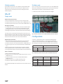
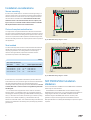
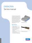
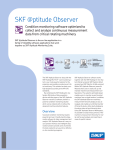
Installation Guide
CMON 2504
Acoustic Emission (AE) Interface Card for the SKF Multilog On-line
System IMx
Introduction
This document describes the installation of the CMON 2504 DIN
card and the CMSS-ONL-2504 cable assembly into an SKF Multilog
On-line System IMx.
Requirements
The following tools are required to install the CMON 2504 and
CMSS-ONL-2504 into the IMx:
•
•
•
•
J2
J3
Fig. 1. Top view of CMON 2504.
wire cutters
wire strippers
4 mm crosshead screwdriver
4 mm flat blade screwdriver
CMON 2504
The base of the CMON 2504 is identified by the sliding metal clip on
the lower end of the enclosure at the rear of the module. Connectors
J2 and J3 on top of the unit provide power in and signal output. J1 on
the bottom of the unit provides signal input.
J1
Fig. 2. Bottom view of CMON 2504.
CMON 2504 terminal block connections
• J1-1: AE sensor signal / phantom power line (Input +)
• J1-2: AE sensor 0 V return (Input –)
• J1-3: not used
• J2-1: +12 to +24 V DC power supply input (Supply +)
• J2-2: 0 V DC power supply input and signal ground (Supply –)
• J2-3: not used
• J3-1: AE DIN interface demodulated output (Output +)
• J3-2: not used
• J3-3: Signal ground (Output –)
It may be convenient to connect the wires before mounting the
CMON 2504 on the DIN rail.
Fig. 3. Input signal connections from CMSS-ONL-2504 cable to
CMON 2504 J1 (card not yet fitted to DIN rail).
CMSS-ONL-2504
The cable will have been pre-stripped to 125 mm, to aid the
installation process.
CMSS-ONL-2504 wires
• Blue and green for AE signals
• Red and black for ICP signals
The drain wires from the two shields are twisted together and may
be connected to the IMx ground rail, if required.
IMx-S
Single module
AE sensor signal connections
• Route the signal cable through a port on the enclosure base
• Connect the blue wire from the sensor cable to CMON 2504 J1-1
• Connect the green wire from the sensor cable to CMON 2504 J1-2
ICP signal connections
Output signal connections
• Make a blue/green twisted pair cable (this may be made from
excess wire cut off during the AE sensor signal connection)
• Connect a blue wire of the output twisted pair to CMON 2504 J3-1
• Connect the green wire of the output twisted pair to CMON 2504
J3-3
• Route the twisted pair to the desired input channel of the IMx
• Blue (signal) should be connected to IMx channel terminal A [+]
• Green (ground) should be connected to IMx channel terminal B [–]
Power connections
• Make a black/red twisted pair cable
• Connect the red wire from the IMx channel terminal PWR (+24 V)
to J2-1
• Connect the black wire from the IMx channel terminal B (0 V)
output to J2-2. This is the same terminal that the green wire has
already been connected to.
• Connect a wire from J3-3 to IMx-S chassis ground.
• Connect the cable screen to IMx chassis ground bar
Fit the CMON 2504 DIN card to the DIN rail, with the metal clip at the
bottom.
• The black and red wires coming from the sensor cable are standard ICP signals and can be connected to the standard IMx channel
• Red (signal) should be connected to IMx channel terminal A [+]
• Black (ground) should be connected to IMx channel terminal B [–]
Terminal A or B refers to IMx-S
Terminal + or - refers to IMx -W
The cable screen is connected to the body of the sensor and is usually grounded by the sensor. Note that where the sensor is glued into
position there may not be an electrical connection and the cable
screen should be connected to the earth strip below the DIN rail.
Fig. 4. ICP signal connections from CMSS-ONL-2504 cable to IMx-S Ch1.
2
Multiple modules
Multiple cards
As each IMx-S channel has +24 V available, multiple CMON 2504
DIN cards are connected in the same way as a single card, each
connected to two channels (one each for the AE signals and the
vibration signals).
Each +12 V relay output can be used to power up to two CMON 2504
DIN cards, meaning that a maximum of four units can be fitted in the
IMx-W without the need for a discrete DIN power supply.
• Connect the power to the four cards as shown in fig. 5
IMx-W
Single cards
AE sensor signal connections
• Route the signal cable through a port on the enclosure base
• Connect the blue wire from the sensor cable to CMON 2504 J1-1
• Connect the green wire from the sensor cable to CMON 2504 J1-2
ICP signal connections
• The black and red wires coming from the sensor cable are standard ICP signals and can be connected to standard IMx channel
• Red (signal) should be connected to IMx channel terminal A [+]
• Black (ground) should be connected to IMx channel terminal B [–]
The cable screen is connected to the body of the sensor and is usually grounded by the sensor. Where the sensor is glued into position
there may not be an electrical connection and the cable screen may
need to be connected to the earth strip below the DIN rail.
Output signal connections
• Make a blue/green twisted pair cable (this may be made from
excess wire cut off during the AE sensor signal connection)
• Connect a blue wire of the output twisted pair to CMON 2504 J3-1
• Connect the green wire of the output twisted pair to CMON 2504
J3-3
• Route the twisted pair to the desired input channel of the IMx
• Blue (signal) should be connected to IMx channel terminal A [+]
• Green (ground) should be connected to IMx channel terminal B [–]
Power connections
• Make a black/red twisted pair cable
• Connect the red +24 V wire from the IMx relay driver CH1 +12 V to
CMON 2504 J2-1
• Connect the black 0 V wire from the IMx CAN bus GND to
CMON 2504 J2-2
• Connect a wire from J3-3 to IMx-W chassis ground
• Connect the cable screen to IMx chassis ground bar
Fit the CMON 2504 DIN card to the DIN rail, with the metal clip at the
bottom.
Fig. 5. Power connection for four CMON 2504 DIN cards fitted in IMx-W.
Configuration
In order to configure IMx-S, IMx-T or IMx-M and SKF @ptitude
Analyst / SKF @ptitude Observer, it is necessary to position DIP
switches in the used channels as shown in figs. 6 and 7. Changes to
DIP settings should only be made when the IMx unit is powered off.
Terminal
DIP Settings position: 123456
+
A
–
B
100100
Fig. 6. DIP switch positions for IMx-S, IMx-T and IMx-M channels 1-8.
Terminal
N.C.
P
+
A
–
B
Shield
S
DIP A Settings
DIP B Settings
100100
0010
Fig. 7. DIP switch positions for IMx-M channels 9-16.
3
Installation considerations
IMx-S
Sensor mounting
gE
AEE
100110
100100
Ch1
P
In most cases, the AE sensor is mounted on a bearing housing or a
machine casing. Hence, the material of the casing and the distance
between the source and the sensor can have a significant effect on
the attenuation of the AE wave. It is vital that the surface onto
which the sensor is to be mounted must be free of paint, coatings or rust, have a smooth machine finish and have a suitable
AE couplant between the sensor and the surface.
Chx
Ch2
B P
A
A
P
B
Chx
A
B
P
Chx
A
x
B
P
Chx
A
B
P
Chx
A
B
P
A
Chx
B
P
A
Chx
B
P
A
Chx
B
P
A
Chx
B
P
A
B
x
J3-3
J3-2
J3-1
J2-3
J2-2
J2-1
J3
J2
CMON 2504
J1
Red
Black
Blue
x
Green
Cable screen
The right choice of couplant and adhesives between the interfaces
are vital in order to avoid attenuation of AE. It is important to remove
all traces of air between the mating surfaces (even smooth ones) by
means of a couplant with an AE impedance matched closely to steel,
and with the ability to last for the required period of time required for
that application.
Chassis ground bar
To CMSS 786M sensor
Fig. 8. CMON 2504 wiring diagram – IMx-S.
IMx-W
Stud method
gE
Ch1
+
Relay driver
AEE
Ch2
-
+
-
Chx
+
Chx
+
-
+
x
Chx
+
-
Chx
-
+
Chx
-
+
Chx
-
+
Chx
-
+
Ch1
-
Ch2
D0 +12V D0 +12V
CAN
H
CAN
L
CAN
RS485
GND
CAN
A
B
GND
x
J2-3
J2-2
J2-1
J3
J2
CMON 2504
Table 1
J1
Stud method specifications
Red
To
Surface preparation toolkit
Black
Blue
J1-3
J1-2
J1-1
From
Chx
-
J3-3
J3-2
J3-1
The stud method provides the best results with least attenuation of
the AE. It also has the benefit of having only one interface and not
requiring any adhesive. The mating surface on the bearing or
machine housing should be prepared in accordance with the
specifications provided in the following table.
Stud model
J1-3
J1-2
J1-1
Choice of couplant and adhesives
x
Green
Cable screen
CMSS 30168700
CMSS 30168701
CMSS 30168703
1/4-28
1/4-28
1/4-28
1/4-28
M8
M6
CMAC 9600-01
CMAC 9600-02
CMAC 9600-10
Chassis ground bar
To CMSS 786M sensor
Fig. 9. CMON 2504 wiring diagram – IMx-W.
In cases where it is not possible to drill and tap a hole to allow the
stud method to be used, the sensor glue mount that is included with
the cable assembly should be used. It should be fixed to the
mounting surface using a thin layer of Loctite 480 adhesive. The use
of other adhesives or sensor mounts can significantly attenuate
the AE signal.
For a small number of applications which utilise an “insulated
bearing” design, it is preferable to also use an insulated “adhesive
mounting pad” method by adhering a CMSS 910MI cementing stud
with 1/4”-28 male to the surface of the bearing or machine housing
and then use a suitable couplant (e.g., Geocel Marine Silicone)
between it and the AE sensor. This isolated mounting stud allows the
sensor to be isolated from the bearing thus preventing any potential
ground loops.
4
SKF CMON 2504 Installation
Validation
It is recommended that installations of the CMON 2504 be validated
before they are commissioned.
All installations of the CMON 2504 must be validated using a
digital voltmeter. Furthermore, it is recommended that in addition to
using a digital voltmeter, the entire AEE installation should be
validated using the SKF CMAC 2504 acoustic emission pulse
generator to inject a known signal into the installation site and
SKF @ptitude Observer / SKF @ptitude Analyst to inspect the system
response.
1, CMON 2504 Installation Validation
Use the digital voltmeter and the provided flow chart († fig. 12) to
perform initial validation of the CMON 2504 installation. If the
CMON 2504 installation is found to be OK, then you can proceed to
testing the AEE system installation.
2. AEE System Validation
The CMAC 2504 is used to inject a known signal into the bearing. The
system response to the signal is used to validate the entire
installation.
The CMAC 2504 generates a pulse train output with 20 V
amplitude, 2.0 us pulse width, and a repetition frequency of ~70 Hz.
To inject a signal, acoustic emission couplant is applied to the
acoustic emission transducer, the transducer is connected to the
CMAC 2504 and the device is turned on. The transducer is then
placed on the test surface (AE sensor or adjacent to AE sensor
installation site).
Before testing with the CMAC 2504, ensure that the AE sensor is
connected to a CMON 2504 card, which should in turn be connected
to an IMx. SKF @ptitude Observer / @ptitude Analyst should also be
preconfigured to acquire acoustic emission signals.
Testing the system using the CMAC 2504 is recommended in two
steps:
1 Use the CMAC 2504 to inject a signal directly into the AE sensor
before installing the sensor.
2 Then assured that the system is working, install the AE sensor and
then use the CMC 2504 transducer to inject the signal onto the
same flat metallic surface the AE sensor is installed on, ensuring it
is free of paint or residue. Ensure there is a direct transmittance
path between the CMAC 2504 transducer and the AE sensor (e.g.,
no cracks, joints, nuts, bolts, etc., interrupting the path).
The system response for both steps should be viewed in SKF
@ptitude Observer (“live” mode is recommended). The system
response should be an attenuated pulse train with the same
repetition frequency (~70 Hz).
If the system response is not as expected, check the following:
• The AE sensor is fixed and secured on its installation site
• There is acoustic emission couplant on both the AE sensor and the
CMAC 2504 transducer
• There are no cracks, joints, nuts or bolts interrupting the transmittance path between CMAC 2504 transducer and AE sensor
• The cable is connected to the AE sensor
• If none of the above resolve the issue, repeat testing using the
digital voltmeter
• Refer to the CMAC 2504 user manual for further details
Fig. 10. The SKF CMAC 2504 and acoustic emission transducer.
Fig. 11. Response of a correctly functioning AEE system to the CMAC 2504 input. Note the clear pulse train in the time domain, which corresponds
with ~70 Hz in the spectrum.
5
1. Check CMON
2504 Power
Supply
Measure voltage
across J2-1 and J22
>11V
< 11V
Low Power
Power OK
2. Check CMON
2504 input
IMx-W
Check power
supply
External supply
IMx-S
>6.9V & <7.1
Measure voltage
across J1-1 and J12
>7.1V
Check wiring
Check wiring and
IMx DIP settings
<6.9V
Sensor & cable OK
Check cable
polarity
Polarity OK
Cable fault
Polarity wrong
Correct the
polarity
3. Check CMON
2504 output
<0.1V
Measure voltage
across J3-1 and J33
CMON 2504 OK
>0.1V
CMON 2504
fault / bad power
ground
Proceed to CMAC
2504 testing
Fig. 12. CMON 2504 installation validation flow chart.
Please contact:
SKF Condition Monitoring Center – Luleå
Aurorum 30, SE-977 75 · Luleå, Sweden
Tel: +46 (0)31 337 1000 · Fax: +46 (0)920 134 40
Web: www.skf.com/cm
® SKF and MULTILOG are registered trademarks of the SKF Group.
Loctite is a registered trademark of Henkel Corporation.
All other trademarks are the property of their respective owners.
© SKF Group 2014
The contents of this publication are the copyright of the publisher and may not be reproduced (even extracts) unless prior written permission is granted. Every care has been taken to ensure the accuracy of the information contained in this publication but no liability can be accepted for any loss or damage whether direct, indirect or consequential arising out of the use of the information contained herein. SKF reserves the right to alter any part of this publication without prior notice.
PUB CM5115/4 EN · May 2014
skf.com
Check wiring