1
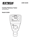
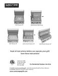
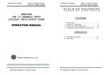
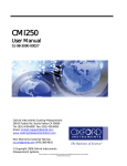
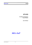
User’s Manual for The T Meter
T Meter
Part #: TMETER (3 parameter model)
www.aciconcrete.net
T101-001 Issue 1
Table of Contents
Getting Started
5
Changing Batteries
6
Making a Measurement
7
Calibrating the Meter
8
Set Up Procedure
9
Error Codes
10
Specifications
11
2
Caution
The pick-up is extremely sensitive to shocks. When positioning the instrument onto the
Surface to be measured, carefully place the pick-up onto the surface to avoid damage.
When positioning the pick-up onto the calibration standards surface, ensure that is
positioned over the surface to measure as shown.
Direction of pick up travel
Direction of pick up travel
REFERENCE SPECIMEN
Ra = 5.81 µm
Calibration
standard
Calibrate using this area
3
Control Unit
Release button
Start button
Start
button
Mode
status
Display
Parameter
status
Mode selector
Parameter selector
Traverse Unit
IrDA windows
Stylus
Stylus
On button
4
Getting Started
Storage. The T Meter is supplied in its storage configuration, that is with the Traverse
Unit connected to the Control Unit so as to protect the gauge. Before use, it is
necessary to separate the Traverse Unit from the Control Unit.
Note: In order to prevent damage to the stylus, it is recommended that the unit is
stored in the storage configuration when not in use.
To return the unit to its storage configuration, reverse the above procedure.
Control Unit
To separate, press
here and tilt the
Traverse Unit to
separate as shown.
Traverse Unit
Positioning
Position the Traverse Unit on the surface to
be measured as shown.
Inserting the batteries
The T Meter uses four 3V Lithium 2450 batteries, one in
the Control Unit and three in the Traverse Unit.
To insert the batteries, remove the battery covers as
shown.
Insert the new batteries as shown, taking care to observe
the correct polarity. Replace the battery covers.
After replacing the batteries there will be a short delay
following switch on before normal operation resumes.
5
Removing the batteries
If the T Meter is not going to be used for an extended period of time, it is
recommended that the batteries are removed from both the Control Unit and Traverse
Unit.
To remove the battery from the Control Unit, remove the battery cover and then press
on the edge of the battery at a point adjacent to either of the two cut-outs in the
moulding as shown. The battery can then be tipped out of the Unit. Replace the
battery cover.
To remove the batteries from the Traverse Unit, remove the battery cover and then
press down on the edge of the battery closest to the centre-line of the Unit. The top
battery can then be slid out of the battery compartment. The remaining batteries can
be removed by tipping them out of the Unit. Replace the battery cover.
Battery Disposal
WARNING: DO NOT ATTEMPT TO RECHARGE THE
BATTERIES.
USED BATTERIES MUST BE DISPOSED OF SAFELY IN
ACCORDANCE WITH LOCAL REGULATIONS.
DO NOT INCINERATE.
Battery low indication
During a measurement, if the battery power in either unit is low, then a low battery
indication will be given. The following displays are used to indicate a low battery
condition and to identify the affected unit.
Traverse Unit
battery low
Control Unit
battery low
6
Switching on
The Control Unit is powered whenever the batteries are in
place. The unit automatically enters a power saving mode
after five minutes from the last operation. During power
saving mode the display is turned off. To activate the unit,
press any button. The display will be activated again and
the welcome screen displayed.
The Traverse Unit automatically enters a power saving
mode after five minutes from the last operation. In this mode
a minimal current is drawn, sufficient only to maintain the
power control circuitry. To reactivate the Traverse Unit
press the On button. An LED on the side of the Unit flashes
to confirm activation.
Making a measurement
There are two modes for operating the T Meter:
Connected Mode and Remote Mode.
Connected Mode.
In connected mode the
Control Unit is connected
to the Traverse Unit as
shown before the
measurement is made.
To connect the Control
Unit to the Traverse Unit,
insert the Control Unit as
shown and tilt until the
latch engages.
Remote Mode.
In remote mode the
Control Unit is positioned
within 1m of the Traverse
Unit and data is passed
between the two units over
the IrDA link.
Note: The alignment
between the Traverse Unit
and Control Unit must be
maintained throughout the
measurement process.
7
Operation of the Control Unit is identical, whether the system is in Connected mode or
Remote mode.
On the Control Unit use the Select Parameter button to select the parameter that is
required to be displayed upon completion of the measurement.
Use the Select Mode button to select either metric or inch units as required.
Position the Traverse Unit on the surface to be measured.
If using remote mode, ensure that the line of sight between the infra red transceivers
is unobstructed; maintain the line of sight throughout the measurement.
To begin the measurement press either of the Start buttons.
During the measurement the Control Unit will show the
‘measurement in progress’ display.
Upon successful completion of a measurement the
measured parameter is displayed as shown.
Should an error occur during measurement an appropriate E code will be displayed.
All parameters (not just the selected parameter) are transmitted to the Control Unit at
the same time and temporarily stored. The stored results may then be stepped
through using the Select buttons.
Calibrating the gauge
To ensure accuracy of results, it is recommended that the T Meter be calibrated
periodically using the calibration specimen supplied with the instrument.
Position the Traverse Unit to measure the Calibration Standard supplied with the
instrument ensuring that the traverse is parallel to the edge of the standard and
entirely over the structured surface. DO NOT use any other standard.
Direction of pick up travel
REFERENCE SPECIMEN
Ra = 5.81 µm
Calibrate using this area
Calibration standard
8
On the Control Unit press the Mode Select buttons until √ is indicated on the Mode
status.
Press the Start button on the Control Unit. This will initiate the gauge calibration
procedure.
At the end of the calibration procedure the Control Unit will display the results of the
calibration. The Ra value should be 5.81μm and the Rz value 21.5μm. If an error
occurs an E code is displayed.
Set Up Procedure
The T Meter is set up before leaving the factory. The set-up procedure is used to set
the speed of the traverse unit and the gain of the gauge. Normally it is only necessary
to repeat the set-up procedure after changing the pick-up. However, if it is required to
set up the unit after purchase, the following procedure should be used.
Separate the units ready to use them in Remote Mode.
Turn on the traverse unit and position it on the calibration standard as shown above.
Activate the Control Unit.
With the Control Unit pointing at the IrDA window on the Traverse Unit, press and hold
both selector buttons simultaneously and then press the right-hand start button whilst
still holding the selector buttons. This will initiate the set-up procedure.
Once the procedure has started, release the buttons.
Note that the infra-red link must be maintained throughout the procedure, which takes
about a minute.
During the procedure, the display will show the following Sequence.
The control unit must be kept pointing at the traverse unit during this period. Upon
successful completion of the set-up procedure, the display will show a value.
There are three values stored as follows:
Value 1 – Ra (Roughness Average)
Value 2 – Sp (Concrete Surface Profile – CSP)
Value 3 – STG (Surface Texture Grade)
These values can be viewed by toggling the display using the right-hand Selector
button. Should an error occur during set-up, the procedure will terminate and an E
code will be transmitted to the control unit for display.
“After executing the set-up procedure, the instrument should be calibrated before
making any measurement.”
9
E codes
The following E codes may appear on the display during the course of using the
T Meter.
E=1.
E=2.
E=3.
E=4.
E=5.
E=6.
E=7.
E=8.
E=9.
E=10.
E=11.
E=12.
E=13.
E=14.
Infra Red communication error. This might be caused by loss of the line of
sight between the two units or other interruption of the infra-red connection. –
Repeat the operation.
Measurement attempted when not calibrated. Calibrate the Traverse Unit.
Traverse Unit - Oscillator fault - Re-attempt the operation. If the fault persists,
return the T Meter to a ACI or Taylor Hobson Service Centre for servicing or
repair.
Traverse Unit - Motor Positioning fault - Re-attempt the operation. If the fault
persists, return the T Meter to a ACI Service Centre for servicing or repair.
Traverse Unit - NVRAM Error - Re-attempt the operation. If the fault persists,
return the T Meter to a ACI Service Center for servicing or repair.
Profile Over-range. The surface being measured may exceed the
measurement range of the T Meter. Reattempt the measurement.
Parameter Over-range. The surface being measured may exceed the
measurement range of the T Meter. Re-attempt the measurement.
Traverse Unit - Motor Speed Setup error. Check that the traverse is parallel to
the edge of the calibration standard, then re-try the set-up procedure.
Traverse Unit - Gain Setup error. Check that the traverse is entirely over the
structured area of the standard. Re-attempt the set up procedure or calibration
procedure
Control Unit - Oscillator fault - Re-attempt the operation. If the fault persists,
return the T Meter to a ACI Service Center for servicing or repair.
Traverse Unit - Calibration information download error. Repeat the calibration
procedure.
Traverse Unit - Not set up or set-up information lost. Run the Set up procedure.
<Reserved>
Traverse Unit - Electronic Measurement error – Re-attempt the operation. If the
fault persists, return the T Meter to a ACI Service Centre for servicing or repair.
10
Specification
Traverse length.
Measurement length
Traverse speed
Gauge range
Gauge resolution
Display resolution
Display resolution
Cut off
Uncertainty
Results range
Results range
Stylus
Filter type
Sample spacing
Stylus Force
Batteries
Units
Operating conditions
Size
Weight
5mm (0.2in)
4mm (0.16in)
2mm/s (0.08in/s)
200μm (8000μin)
0.05μm (2μin)
Ra. 0.01μm (1μin)
Sp, STG 0.1μm (1μin)
0.8mm (0.03in) +/- 15%
0.1μm (4μin) or 5% of result, to 95% confidence level
Ra 40μm (1600μin), see ISO 4287:1997
Sp, STG. 199.9μm(8000μin), see CSDA ST115
Diamond conisphere with 5μm nominal radius, 90º tip
angle. Skid radius: 10mm nominal.
2CR, (200:1)
1um
10mN (1gf) max at mid range
Control Unit One x 3V Lithium 2450. Traverse Unit:
Three x 3V Lithium 2450
μm or μin
10 to 35ºC, 80%RH non-condensing
125mm x 80mm x 38mm (4.92in x 3.15in x 1.5in)
200g (7oz)
*3 parameter model only
Protected by US Patent No 6629373 and US Design Patent No D439850
Infra-red communications link
The range of the infra-red (IR) link may be reduced in strong lighting conditions or where there is interference at the
specific wavelengths or frequencies used by the IR devices. Sources of such interference include some fluorescent
lighting products. If operation is affected by such conditions, it may be necessary to reduce the distance between
the two units, shield the infra-red ports from the stray light or use the Duo in its Connected mode.
Disposal of the Surtronic Duo
When disposing of the T Meter, please remove the batteries as described above. Dispose of the
batteries and the instrument independently in accordance with local regulations. The instrument
should be disposed of as Waste Electrical and Electronic Equipment (see EU Directive
2002/96/EC) and not put into general waste.
Declaration of Conformity
Distributor Name: ACI, Inc.
Distributor Address: 124 Sidon Rd., Rose Bud, AR 72137 419-408-5906
Manufacturer’s Name: Taylor Hobson Limited
Manufacturer’s Address: 2 New Star Road, Leicester, England, LE4 9JQ
It is declared that the products: T Meter 168-7092 (3 parameter) conform to all applicable requirements of BS EN
50081-1:1992, BS EN 50082-1:1998 and BS EN 61010:2001.
The above product complies with the requirements of the EMC Directive 89/336/EEC as amended.
The above product complies with the requirements of the EMC Directive 73/23/EEC as amended.
11
12