1
O
L
E
V
E
D
P
T
N
E
M
PC
Eur
oso
1..
2..
ft-u
3..
k.c
4..
om
5..
6..
7..
bility
Relia
ions
Solut
8..
M
N
A
C
A
F
U
T
IN
R
U
G
S
R
O
P
P
U
T
E
C
N
A
N
E
T
IN
A
M
Pc-Check
R
Diagnostic Software
User Manual
Nobody
checks
out
PCs
better
than
Eurosoft
SM
Pc-Check
®
Diagnostic Software
Eurosoft (UK) Ltd
3 St Stephen's Road
Bournemouth
Dorset BH2 6JL
England
Tel: +44 (0)1202 297315 Fax: +44 (0)1202 558280
EMAIL: [email protected]
Web Site: http://www.eurosoft-uk.com
072004MPCCV5.65
Pc-Check
Diagnostics for AT-Style Personal Computers
Copyright © 1988 - 2004, Eurosoft (UK) Ltd, All Rights Reserved.
No reproduction of any kind, in part or whole, is allowed without the
express and prior written approval of the company, its authors or
publishers.
DISCLAIMER
Eurosoft (UK) Ltd has endeavoured to meet all technical areas associated
with the products in this manual. Any changes, omissions or errors
are of no liable consequence, actual or otherwise to the company, its
authors or publishers. Further, any changes to the products or
documentation may take place at any time without obligation of
Eurosoft (UK) Ltd, to notify any person of these changes.
Products mentioned or noted in this document are for identification
purposes only and may be trademarks and/or registered trademarks of
their respective companies or owners.
Eurosoft (UK) Ltd. 1988-2004. Pc-Check, QA+ and QAPlus are registered
trademarks of Eurosoft (UK) Ltd. PC Builder, QA+Win32, QA+FE Service
Center, Virtual QA+, Virtual Pc-Check, CD-Check, Preferred POST
Board, USB Preferred Port Plug, SIBs, CDT, DVDT, EuroBIOS, EuroDOS
are trademarks of Eurosoft (UK) Ltd. All other product trademarks are
recognised as belonging to their respective owners. Products or information
may change without notice.
Pc-Check is Copyrighted by Eurosoft (UK) Ltd.
Intellectual Property solely owned by Eurosoft (UK) Ltd.
Design & Copyright © 2004 Eurosoft (UK) Ltd.
Published by Eurosoft (UK) Ltd 2004. All rights reserved.
ACKNOWLEDGMENT
Floating point arithmetic in Pc-Check is implemented via “SoftFloat”.
Contact Information
Eurosoft (UK) Ltd.
Head Office
3 St. Stephen’s Road
Bournemouth
Dorset BH2 6JL
United Kingdom
Tel +44 (0)1202 297315
Fax +44 (0)1202 558280
Email: [email protected]
Website: www.eurosoft-uk.com
Eurosoft (US) Inc.
North American Sales Office
Suite 101, One Davol Square
Providence, RI 02903
USA
US Toll Free Tel +1 (888) 980-9595
International Tel +1 (401) 751-9595
Fax +1 (401) 751-0088
Email: [email protected]
Website: www.eurosoft-us.com
Information & Sales
Europe
United States
Pacific Rim
[email protected]
[email protected]
[email protected]
Support
Europe
United States
Pacific Rim
[email protected]
[email protected]
[email protected]
Visit our website for fast on-line sales and the latest news
about the best Eurosoft solutions for you. Thank you!
Please contact your nearest Eurosoft office should you
require additional software or accompanying manuals.
Pc-Check
Diagnostics for AT-Style Personal Computers
This page is intentionally left blank
Contents
Contents
Section 1
Pc-Check®From Eurosoft ............................................ 1.1
Section 2
GETTING STARTED WITH Pc-Check® ..................... 2.1
2.1
Unpacking ................................................................................................... 2.1
2.2
Program Diskette Back-Up ......................................................................... 2.2
2.2.1
2.2.2
2.3
Loading DOS Pc-Check® ........................................................................... 2.3
2.3.1
2.3.2
2.3.3
2.4
Command Line Operation ................................................................ 2.4
Disabling the Extended Memory Manager .................................... 2.10
Loading Pc-Check® From Diskette .............................................. 2.10
Loading Pc-Check® Self-Boot .................................................................. 2.10
2.4.1
2.4.2
2.4.3
2.4.4
2.5
Replacing a Damaged Program Diskette ......................................... 2.2
Backing-up Your Original Diskette .................................................. 2.3
CMOS Setup ...................................................................................... 2.10
Loading Pc-Check® Self-Boot From Diskette ............................. 2.11
Command Line Switches ................................................................. 2.11
Limitations ....................................................................................... 2.12
Main Menu ............................................................................................... 2.12
Section 3
SYSTEM INFORMATION MENU ................................ 3.1
3.1
System Overview ........................................................................................ 3.1
3.2
Hardware ID Image Menu .......................................................................... 3.1
3.2.1
3.2.2
3.2.3
Write System HII as XML File ........................................................ 3.2
Compare System HII with XML File ............................................... 3.2
Write HII as TXT File ...................................................................... 3.2
3.3
System Management Information ............................................................... 3.3
3.4
PCI Bus Information ................................................................................... 3.3
3.5
IDE Bus Information .................................................................................. 3.4
3.6
PCMCIA/CardBus Information ................................................................. 3.4
3.6.1
3.6.2
3.6.3
PCMCIA Host Adapter Information ............................................... 3.4
PCMCIA Socket Information ........................................................... 3.6
PCMCIA Card Information .............................................................. 3.8
3.7
Interrupt Vectors ....................................................................................... 3.10
3.8
IRQ Information ....................................................................................... 3.10
3.9
Device Drivers .......................................................................................... 3.11
3.9.1
3.9.2
3.10
Pc-Check DOS .................................................................................. 3.11
Pc-Check Self-Boot ......................................................................... 3.11
MHz Monitor ........................................................................................... 3.11
Pc-Check
3.11
Diagnostics for AT-Style Personal Computers
I/O Port Viewer ......................................................................................... 3.12
3.11.1
3.11.2
3.11.3
3.11.4
3.11.5
Output Device .................................................................................. 3.12
I/O Search Start ................................................................................ 3.12
Show Active Ports Only .................................................................. 3.12
Accept Settings as Shown Above .................................................... 3.13
I/O Port Viewer ................................................................................. 3.13
3.12
Memory Viewer ........................................................................................ 3.13
3.13
Sector Viewer ............................................................................................ 3.14
3.14
APM Information ..................................................................................... 3.16
3.14.1
3.14.2
3.14.3
3.14.4
3.14.5
3.14.6
3.15
ACPI Information ..................................................................................... 3.19
3.15.1
3.15.2
3.16
Select Device .................................................................................... 3.16
Change Power State ......................................................................... 3.16
View Power Status ............................................................................ 3.17
Indicate CPU Usage ......................................................................... 3.17
Get PM Event .................................................................................. 3.18
Change Interface Mode ................................................................... 3.19
System Description Tables .............................................................. 3.20
ACPI Address Ranges ....................................................................... 3.21
CMOS RAM Utilities .............................................................................. 3.22
3.16.1
3.16.2
3.16.3
CMOS RAM Editor (Setup) ............................................................ 3.22
Save CMOS to Floppy A: ................................................................ 3.24
Restore CMOS from Floppy A: ...................................................... 3.25
3.17
Command Line Options ............................................................................ 3.25
3.18
System File Editor / Edit CMDLINE.TXT .............................................. 3.25
Section 4
ADVANCED DIAGNOSTIC TESTS ............................. 4.1
4.1
Processor Diagnostics ................................................................................. 4.1
4.2
Motherboard Diagnostics ........................................................................... 4.3
4.3
Memory Diagnostics .................................................................................. 4.5
4.3.1
4.3.2
4.3.3
4.3.4
4.3.5
4.3.6
4.3.7
4.3.8
4.3.9
4.3.10
4.3.11
4.3.12
Test System Memory ........................................................................ 4.7
Test Module ........................................................................................ 4.7
Test Range .......................................................................................... 4.7
User Pattern Test ............................................................................... 4.7
Test Cache Memory .......................................................................... 4.7
Benchmark Memory .......................................................................... 4.7
Cache Profiler .................................................................................... 4.8
Part Details ......................................................................................... 4.8
Test Video Memory ........................................................................... 4.8
Set Test Set ......................................................................................... 4.8
Set Test Reps ...................................................................................... 4.9
Set uTL Test Time ............................................................................. 4.9
Contents
4.4
Floppy Disk Diagnostics ............................................................................ 4.9
4.4.1
4.4.2
4.4.3
4.4.4
4.4.5
4.4.6
4.5
Select Floppy Disk Drive ................................................................ 4.10
Write Protect Test ........................................................................... 4.10
Linear Read Test .............................................................................. 4.10
Non-Destructive Write Test ........................................................... 4.10
Random Read/Write Test ................................................................ 4.10
View Floppy Disk Test Results ....................................................... 4.10
Hard Disk Diagnostics .............................................................................. 4.11
4.5.1
4.5.2
4.5.3
4.5.4
4.5.5
4.5.6
4.5.7
4.5.8
4.5.9
4.5.10
4.5.11
4.5.12
4.5.13
Menu Layout .................................................................................... 4.11
The Hard Disk Tests Menu ............................................................. 4.11
The Select Drive Menu ................................................................... 4.11
Test Settings Menu ........................................................................... 4.12
Read Test ........................................................................................... 4.17
Read Verify Test ............................................................................... 4.18
Non-Destructive Write Test ........................................................... 4.18
Destructive Write Test .................................................................... 4.19
Mechanics Stress Test ...................................................................... 4.19
Internal Cache Test ......................................................................... 4.20
SMART Immediate Test .................................................................. 4.20
View Error Log ................................................................................. 4.21
Utilities Menu ................................................................................... 4.21
4.6
ATAPI Devices ......................................................................................... 4.22
4.7
Serial Port Diagnostics .............................................................................. 4.22
4.7.1
4.7.2
4.7.3
4.7.4
4.7.5
4.7.6
4.7.7
4.7.8
4.8
Parallel Port Diagnostics ........................................................................... 4.25
4.8.1
4.8.2
4.8.3
4.8.4
4.8.5
4.8.6
4.8.7
4.9
Serial Port Selection Menu ............................................................. 4.23
Serial Port Tests Menu .................................................................... 4.23
Select Another Serial Port ............................................................... 4.24
Run All Serial Port Tests ................................................................. 4.24
Serial Port Line Control Test ......................................................... 4.24
Serial Port Handshake Test ............................................................. 4.24
Serial Port Loopback Test .............................................................. 4.24
Serial Port Internal FIFO Test ....................................................... 4.24
Parallel Port Selection Menu .......................................................... 4.25
Parallel Port Tests Menu ................................................................ 4.25
Select Another Parallel Port ........................................................... 4.25
Run All Parallel Port Tests ............................................................. 4.25
Parallel Port Controller Test .......................................................... 4.26
Parallel Status Port Test .................................................................. 4.26
Parallel Port Interrupt Test ............................................................ 4.26
Modem Diagnostics .................................................................................. 4.26
4.9.1
4.9.2
4.9.3
4.9.4
Modem Selection Menu ................................................................... 4.28
Modem Tests Menu ......................................................................... 4.28
Select Another Modem .................................................................... 4.28
Change Local Baud Rate .................................................................. 4.28
Pc-Check
4.9.5
4.9.6
4.9.7
4.10
Pc-Check® Print Test ..................................................................... 4.30
Keyboard Diagnostics ............................................................................... 4.32
4.11.1
4.11.2
4.11.3
4.11.4
4.12
Modem Register/Loopback Test .................................................... 4.28
User Interactive Modem Test ......................................................... 4.29
Pc-Check Dumb Terminal ............................................................... 4.29
Printer Diagnostics .................................................................................... 4.29
4.10.1
4.11
Diagnostics for AT-Style Personal Computers
Verify Keyboard ............................................................................... 4.33
Keyboard Controller Tests .............................................................. 4.34
Key Repeat Test ............................................................................... 4.34
Keyboard LED Test ......................................................................... 4.34
Mouse Diagnostics ................................................................................... 4.34
4.13
Joystick Diagnostics ................................................................................. 4.36
4.14
Turbo Switch Test .................................................................................... 4.36
4.15
Video Diagnostics ...................................................................................... 4.37
4.15.1
4.15.2
4.15.3
4.15.4
4.15.5
4.15.6
4.15.7
4.15.8
4.15.9
4.15.10
4.15.11
4.15.12
4.16
Audio Devices ........................................................................................... 4.40
4.16.1
4.16.2
4.16.3
4.17
Speaker Test ..................................................................................... 4.40
FM Synthesizer Test ........................................................................ 4.41
PCM Sample Test ............................................................................ 4.41
CD-ROM/DVD Diagnostics .................................................................... 4.41
4.17.1
4.17.2
4.17.3
4.17.4
4.17.5
4.17.6
4.18
Warning – Video Test Initialisation ............................................... 4.37
Video Driver Information ............................................................... 4.37
Select Modes for Testing ................................................................. 4.37
Check Gamma .................................................................................. 4.38
Colour Linearity ............................................................................... 4.38
Colour Purity Test ........................................................................... 4.38
True/High Colour Test ..................................................................... 4.38
Alignment Test ................................................................................. 4.39
LCD Test ........................................................................................... 4.39
Test Card ........................................................................................... 4.39
Video Memory .................................................................................. 4.40
Exit Tests .......................................................................................... 4.40
Select CD/DVD Device .................................................................... 4.42
CD/DVD Transfer Test ................................................................... 4.42
CD/DVD Random Seek Test ........................................................... 4.42
CD/DVD Tray Test .......................................................................... 4.43
Audio CD Disc Player ...................................................................... 4.43
CD/DVD Test Disc Read .................................................................. 4.43
USB ........................................................................................................... 4.44
4.18.1
4.18.2
4.18.3
4.18.4
Test USB Controllers ....................................................................... 4.44
USB Functional Tests ...................................................................... 4.44
USB Device Information ................................................................ 4.44
Exit USB Tests ................................................................................. 4.44
Contents
Section 5
CONTINUOUS BURN-IN TEST ................................... 5.1
5.1
Immediate and Deferred Burn-In ................................................................ 5.1
5.2
The Burn-In Menu ...................................................................................... 5.2
5.2.1
5.2.2
5.2.3
5.2.4
5.2.5
Load Burn-In Script ........................................................................... 5.2
Save Burn-In Script ............................................................................ 5.2
Change Options .................................................................................. 5.2
Select Tests ......................................................................................... 5.3
Perform Burn-In Tests ...................................................................... 5.3
5.3
Running Pc-Check® with BEEP Codes ...................................................... 5.4
5.4
SIB (Status Indicator Box) ......................................................................... 5.5
5.5
Post Codes and BEEP Codes ...................................................................... 5.7
Section 6
SCSI UTILITIES ........................................................... 6.1
Important Information Before You Begin ................................................................ 6.1
6.1
Identify SCSI Devices ................................................................................. 6.1
6.2
SCSI Low Level Format .............................................................................. 6.1
6.2.1
6.2.2
6.2.3
6.3
Interleave Entry ................................................................................. 6.2
Format Key ......................................................................................... 6.2
Format In Progress ............................................................................ 6.2
Assign SCSI Bad Blocks ............................................................................. 6.2
6.3.1
6.3.2
6.3.3
6.3.4
6.3.5
Add Bad Block .................................................................................... 6.3
Delete Bad Block ................................................................................ 6.3
Clear List ............................................................................................. 6.3
Sort List ............................................................................................... 6.4
Write Bad Blocks ............................................................................... 6.4
Section 7
SHOW RESULTS SUMMARY ..................................... 7.1
Section 8
PRINT RESULTS REPORT .......................................... 8.1
Section 9
PROBLEM REPORTING ............................................. 9.1
9.1
Introduction ................................................................................................ 9.1
9.2
Technical Problem Report Forms (TPRs) .................................................. 9.1
Appendix A
HOW TO CREATE SELF-BOOT BATCH FILES ........ A.1
Appendix B
LIST OF POWER MANAGEMENT EVENTS .............. B.1
Appendix C
DISABLING THE EXTENDED MEMORY MANAGER C.1
Pc-Check
Appendix D
Diagnostics for AT-Style Personal Computers
ADVANCED XML OPTIONS FOR HII FILES .............. D.1
D.1
Basic HII Facilities ..................................................................................... D.1
D.2
Advanced Facilities .................................................................................... D.2
D.3
Modifying HII XML Files ........................................................................ D.2
Glossary
TERMS IN COMMON USE .......................................... G..1
Section 1
Introduction
Section 1
Pc-Check®
From Eurosoft
Pc-Check is a fast, accurate and easy-to-use diagnostic tool from
Eurosoft that enables you to check completely the configuration and
reliable operation of IBM-AT-compatible PCs. Pc-Check is extremely
useful to manufacturers and repairers of PCs, informing all user levels
on the architecture and operational reliability of PC hardware. Stringent
routines test the entire PC by exercising each hardware component
and indicating those areas that fail to respond perfectly.
Note: We recommend that you run Pc-Check regularly to ensure that
your machine is up to standard.
When you run the Pc-Check software on your PC, its simple menu
selection allows you to choose the tests and reports you require. The
program can test that all the components are functioning correctly. It
provides a thorough summary of the system configuration, including
all memory areas, floppy, hard and CD-ROM/DVD drives, the nature
and address of I/O ports, type of display, and so on. You are then
guided by a menu to select the advanced diagnostic facilities that will
lead you easily and logically to the area causing problems, or to verify
hardware accuracy.
Although this manual assumes that the reader has a good understanding
of PC architecture, it can be used equally well by those who are less
confident to determine whether a fault actually exists. The user will be
able to follow the steps shown on the test screens, and the following
chapters in this manual are arranged in the same order as the tests.
When more help is needed, this manual provides the information.
All that is needed for Pc-Check to test, verify and report in detail on
your PC is: a working system core, a functioning central processor
unit, a floppy disk drive, and enough memory to load the program.
Pc-Check is supplied with all the instructions and software you need
to test your system. Loopback connectors are available from Eurosoft
Page 1.1
Pc-Check
Diagnostics for AT-Style Personal Computers
to test the peripheral ports properly. If you are using Pc-Check DOS,
instead of Pc-Check Self-Boot, you may also need to create a special
‘Clean Boot’ diskette if you have extended memory (see Section 2.3.2
for instructions).
Pc-Check Self-Boot allows you to perform diagnostics without fear
of interference by memory managers, device drivers and even DOS or
Windows. You will not need to edit your normal CONFIG.SYS or
AUTOEXEC.BAT files to bypass the utilities you normally need to run
standard applications. These are automatically eliminated and thus
ensure a ‘clean’ testing environment independent of the operating
system.
Pc-Check Self-Boot runs independently of the machine’s normal
operating system so there is no need to have either a bootable DOS
diskette or a hard disk to run tests.
Note: Pc-Check is one of a range of products available from Eurosoft.
Other items include diagnostic hardware and utility programs
for PC fault analysis and testing.
Contents and Index
Rather than provide an Index, this manual contains a comprehensive
Contents Section, which inherently lists every sub-section topic in the
same logical order as the items in the Pc-Check menus. Where the
main reference for a given topic has additional cross-references, these
will then be found within the text itself.
System Requirements
Pc-Check requires approximately 500KB of base memory and is
designed to operate on machines which are 100% IBM PC-AT
compatible. Pc-Check does not support XT machines. In some cases,
testing will be limited to the hardware present, i.e. certain memory
tests require a 386 or higher processor.
Page 1.2
Section 2
Getting Started
Section 2
GETTING STARTED WITH Pc-Check®
2.1
Unpacking
Confirm that your Pc-Check package was in good physical condition
when it was supplied to you.
Check that it contains the following items:1.
A package containing either:
one 3.5" program diskette, or:
two 3.5" diskettes (a program diskette and a backup diskette).
2.
This manual
3.
Loopback plugs (generally included with the package)
4.
USB Preferred Port plug (generally included with the package)
5.
Your Product Registration Card.
6.
Kitbag.
IMPORTANT
Promptly registering your product with us entitles you to
immediate support and provides you with the opportunity
to be notified of updates, enhancements and special
offers on maintenance and diagnostic products from
Eurosoft. Please be certain to return your completed
registration card right away.
Page 2.1
Pc-Check
Diagnostics for AT-Style Personal Computers
NOTES ON RUNNING Pc-Check
Do not run Pc-Check DOS on a PC that is being used as
a file server, or under any version of Windows, OS/2 or
Desqview. Disable any Power Management system.
If operating directly from floppy diskette, do not remove
the diskette while running the program, except to replace
it with a data diskette when writing/reading special files
to/from the drive for a specific purpose: in that case
replace the program diskette immediately afterwards.
References are made below to diskette drive A: for
simplicity. If you work with drive B: instead, merely
substitute B: for A: consistently.
2.2
Program Diskette Back-Up
IMPORTANT
If you have received a copy-protected program diskette
accompanied by a backup diskette, read the instructions
below under “Replacing a damaged program diskette”.
If you have received a single program diskette, follow the
instructions under “Backing-up your original diskette”.
2.2.1
Replacing a Damaged Program Diskette
If you have received a copy-protected program diskette, then a
backup diskette of the software will also have been included in your
package. Please do not use the backup diskette unless your master
diskette program becomes corrupted.
Please send any corrupted software program diskettes back to your
nearest Eurosoft address, or to an authorised representative, for
replacement.
Once the software diskette has been received, replacement is free of
charge within the upgrade period of one year.
Page 2.2
Section 2
2.2.2
Getting Started
Backing-up Your Original Diskette
1.
Before you begin testing with Pc-Check make a copy of your
original Pc-Check diskette on a normal working PC. DO NOT
use the DOS ‘COPY’ command, or “drag-and-drop” copying
in Windows® Explorer. Make sure the Pc-Check original diskette
is write-protected to prevent loss if you make a mistake.
2a.
To back-up your diskette using Windows®:
Place the original diskette in the A: drive, and run Windows®
Explorer. Right-click over the floppy drive icon, and select
“Copy disk...” from the drop-down list. Follow the on-screen
instructions. For the copy, use a blank, formatted, writeenabled diskette of the same type as the original.
2b.
Alternatively, under DOS, use ‘DISKCOPY’ as follows:Obtain a diskette of the same type as the original. The diskette
does not have to be formatted but if it is formatted and contains
data, the data will be lost.
Then enter:
DISKCOPY A: A:
Follow the on-screen instructions, inserting the Pc-Check original
diskette when you are asked for the “source disk”, and the disk
to which you are copying Pc-Check when you are asked for
the “target disk”. You may be asked to insert the source and
target disks more than once if your machine does not have the
memory to make the transfer in one operation.
3.
2.3
Store your Pc-Check original diskette in a safe place.
Loading DOS Pc-Check®
(for Pc-Check Self-Boot see Section 2.4)
Note: To perform the Memory Tests or obtain PCI information, you
must disable all extended memory managers (See Section 2.3.2).
Page 2.3
Pc-Check
2.3.1
Diagnostics for AT-Style Personal Computers
Command Line Operation
Pc-Check can be run either interactively under user keyboard control,
as described in later sections of the manual, or via command line
operation, which requires little or no user attention.
You can run Pc-Check from the command line by giving certain
switch parameters which are described in the following paragraphs.
These ‘switches’ make Pc-Check run either without attention, or with
only minimal attention when user acknowledgement of visual
information is required.
The switches follow the normal DOS convention and are explained below.
All arguments (including the name of the Burnfile) are non-positional
and case-insensitive. The argument template is as follows:
PCCHECK [/BW] [/EC] [/MM Num] [/MP Num] [/RF Name]
[/RA] [/RC] [/RP] [/RM Name] [/RS Num] [/RT Name]
[/BB] [/BC] [/BD] [/BE Num] [/BM Num] [/BP] [/BS]
[/JF Name] [/JA] [/JT] [/JS] [/CS Name] [/CR Name]
[/CT] [/ID Name] [/IF] [/IT] [/IC Name] [/IO Name]
[/HMD Time] [/HMC Num] [/HDD Time] [/HDL Num] [/IE]
[/QM] [/UM] [/MI] [/MH Num] [/KS] [/ND] [/DS] [/LD]
[/UP Num] [Burnfile Name]
Where: Square brackets [ ] indicate optional items; ‘Name’ and ‘Num’
indicate the need to supply appropriate information.
Note: Starting without a burn-in file brings up the main menu.
/BW forces the use of a monochrome colour scheme.
/EC
enables loading of the Configuration Manager.
/MM specifies a Microsoft compatible mouse on the specified
COM port.
/MP specifies a PC-mouse compatible on the specified COM port.
Page 2.4
Section 2
Getting Started
/RF should be followed by the filename (and path) of the Burn-In
tests report file. This is the same data as you get from the ‘Print
Results Report’ when you select that option from the Main Menu,
except that the variable fields for the machine name, tester’s name etc.
are left blank (unless modified by /RM and /RT). The filename
supplied may also refer to DOS devices such as PRN for the printer
and COM1 for the first serial port.
Note: If the filename you nominate does not already exist, Pc-Check
creates it for you. If the file does exist, then the new data is
added to the end of the data in the existing file.
/RA modifies the operation of the /RF report generation. The normal
default is only to list the tests actually run during Burn-In, but adding the
/RA switch causes the report to list all tests whether they are run or not.
/RC writes a report after each component during burn-in.
/RP
writes a report after each pass during burn-in.
/RM allows the entered machine name to be displayed in reports
and logs. Maximum of 20 characters. See Note below.
/RS specifies a machine serial number which appears on reports
requested from the command line, and also as the default serial
number when a report is requested interactively. Maximum of 20
characters. See Note below.
/RT specifies a user / tester name which appears on reports requested
from the command line, and also as the default tester name when a report
is requested interactively. Maximum of 30 characters. See Note below.
Note: If the name/number following /RM, /RS and /RT contains
spaces, the text string must be included in double quotes, eg
"John Smith".
If the first character of the name/number following /RF,
/RM, /RS, /RT is ? (for example /RT ?Smith), then an
interactive window appears which allows changes to be
Page 2.5
Pc-Check
Diagnostics for AT-Style Personal Computers
made to, say, what had been specified in a default batchfile.
For example, if the default batch file includes:
/RM machine name /RS ? /RT "John Smith"
then the interactive window appears with the machine name
and tester filled in, and the serial number blank. All three
fields can then be changed.
/BB outputs beep codes when items under test fail. (See Section 5.5
for a definition of each beep code.)
/BC sounds a repeated two-tone beep to indicate completion of
burn-in. This is NOT a BEEP code.
/BD specifies that the system returns to the DOS prompt on test
completion. This is particularly useful when you run the tests from a
batch file. Pc-Check exits with an error level set in the range 0 to 3 as
defined below. A batch file can detect this and initiate different
appropriate action. Required if any reports are to be generated, or if
POST or SIB output is requested.
The error levels provided by /BD are:
0
everything ran, with no errors
1
everything ran but there were failures
2
burn-in was interrupted by the user
3
bad option on the command line.
/BE causes Pc-Check to abort the Burn-In testing if [Number]
amount of errors occur.
/BM allows a ceiling value to be set for the modem baud rate for
burn-in testing. It is advised that an interactive test be used to establish
a sensible maximum value in advance. If this parameter is omitted, the
default strategy described in Section 4.9 is used.
/BP causes Pc-Check to output diagnostic codes to a POST (Power
On Self Test) Card during testing and Burn-In. (See Section 5.5 for a
list of POST Codes.)
Page 2.6
Section 2
Getting Started
/BS commands Pc-Check to use a SIB (Status Indicator Box)
during Burn-In testing. (See Section 5.4 for the use of SIBs.)
/JF should be followed by the filename (and path) into which
error-logging information is inserted during Burn-In testing. This
journal will contain a list of the tests that failed during Burn-In stating
the device reference, if applicable, and the pass number in which the
device failed. The filename supplied may also refer to DOS devices
such as PRN for the printer and COM1 for the first serial port, if not
self-booted. The journal can be viewed with any text editor.
Note: If the filename you nominate does not already exist, Pc-Check
creates it for you. If the file does exist, then the new data is
added to the end of the data in the existing file.
/JA writes a journal log line for each selected component which is
found to be or appears to be absent (for example if no CD-ROM drive
is present).
/JT logs the start and end of each test in the journal: if not included,
then only failed tests are logged.
/JS
writes a summary of the tests to the journal at the end of testing.
/CS specifies a filename to which to save the contents of CMOS
memory.
/CR specifies a filename from which to restore the contents of
CMOS memory.
/CT
reboots the machine after performing CMOS operations.
/ID specifies a filename to which to write a hardware ID image
(HII) or machine ID descriptor. Default format is .XML.
/IF
causes the file requested by /ID to be output as text (.TXT).
/IT
exits program after writing hardware ID image (HII).
Page 2.7
Pc-Check
Diagnostics for AT-Style Personal Computers
/IC specifies the filename of a reference image used as a comparison
with current burn-in HII.
/IO specifies an output filename which lists differences between
the burn-in HII and the reference image.
/HMD Hard Disk Media Duration: sets the duration limit for hard disk
media tests (adaptive coverage). Format: [xxh] [xxm] [xxs]. Ignored
if the time actually required for the disk tests is less than this value.
/HMC Hard Disk Media Coverage: sets the level of coverage for hard
disk media tests (fixed coverage). Entered as a number between 1 and
100, indicating the percentage coverage required.
/HDD Hard Disk Device test Duration: sets the duration limit for hard
disk device tests (adaptive level). Format: [xxh] [xxm] [xxs]. Ignored
if the time actually required for the disk tests is less than this value.
/HDL Hard Disk Device testing Level: sets the test level for hard disk
device tests (fixed level). Entered as a number between 1 and 100,
indicating the percentage coverage required. For example, if set to 50,
then only half the amount of tests will be performed.
/IE Ignore ECC errors if correction of memory data is successful.
During a memory test, if the ECC has successfully corrected an error,
the memory test would normally still fail the component: this switch
allows suppression of these failures.
/QM suppresses module mapping assumptions in the Memory Test.
Normally, Pc-Check uses information obtained from the system to
deduce which physical addresses map onto which memory modules,
in order to pin-point which module is faulty. Sometimes the system
information is incomplete or very obviously inaccurate: in these cases
Pc-Check will attempt to deduce the mapping if it is safe to do so.
However, if the /QM switch is set, then if Pc-Check detects the
slightest problem with the system data, it will instead resolve all
memory to one device entitled “nnnMB accessible system memory”.
Page 2.8
Section 2
Getting Started
/UM Force memory tests to unify modules.
/MI
Enables “Memory Intelligent Preservation” (used for PXE boot)
/MH Set hundredths of a second per MB for uTL Memory Test.
Default 150 (1.5 sec/MB). See Section 4.3.12 for further explanation.
/KS
disables keyboard self-test.
/ND
never disable DMA.
/DS
disables legacy Sound card detection.
/LD
Relax testing of DMA channels 0 and 1.
/UP sets number of USB ports that require test plugs: 0 = all,
default = 1
[Burnfile Name] represents the name of the script file containing the
list of Burn-In tests.
For a full list of command line switches type:
PCCHECK /H or PCCHECK /?
and a list of options will be displayed on the screen. This list is also
available via the System Information Menu (see Section 3.17).
For example, if you want everything recorded, enter a command
similar to that shown below using the file names and extensions of
your choice. If these files are to be stored in a directory that is not the
same directory in which PCCHECK.EXE resides, you must give the
full path ahead of the file name.
PCCHECK /JF ERROR.FIL / RF BURN03.RPT /RA /BD
CONFIG03.DTA
Note: When Pc-Check is started with a Burn-In file, all devices
requested at the time the burn-in file was created will be tested
if they are available.
If preferred, these instructions can be written to a suitably named
BAT file, so that they can be run under DOS in the normal way and
Page 2.9
Pc-Check
Diagnostics for AT-Style Personal Computers
re-used. It is recommended that Pc-Check's own System File Editor
is used for this purpose (accessed via the System Information Menu
- see Section 3.18). Alternatively, the file may be prepared using
another text editor, such as Windows® NOTEPAD, or a DOS editor
for older systems.
The syntax and method of use with Pc-Check Self-Boot differs
somewhat from the above, as described in Section 2.4.
2.3.2
Disabling the Extended Memory Manager
If your computer uses a memory manager, Pc-Check requires this
memory manager to be disabled for certain tests to be performed. See
Appendix C for further information.
2.3.3
Loading Pc-Check® From Diskette
Insert the diskette containing Pc-Check into drive A: and if necessary
set the path to this drive; then type PCCHECK <ENTER>
Note: Alternative start-up commands are used if advanced Burn-In
tests are required (see Sections 5.3 and 5.4).
2.4
Loading Pc-Check® Self-Boot
(for DOS Pc-Check see Section 2.3)
2.4.1
CMOS Setup
Normally a computer is configured so that it will look to see if there is
a floppy disk inserted into drive A: when you switch on or reset.
Pc-Check normally requires the computer to be in this state. However,
if the computer has been set to ignore drive A: as a boot device (by
configuring the CMOS in your BIOS setup), then read the documentation
that comes with your computer for specific details on how to set your
system to boot from drive A:. When you have finished your self-boot
Pc-Check session, remember to set your system back to your standard
configuration.
Page 2.10
Section 2
2.4.2
Getting Started
Loading Pc-Check® Self-Boot From Diskette
1.
Insert the diskette containing Pc-Check in drive A: and switch
on or reset the computer.
2.
After a short while, you will see the Pc-Check Main Menu.
3.
Proceed with your testing but take note of the Limitations (see
Section 2.4.4).
A message is given if you attempt to select a menu option that
is not available.
4.
When you exit Pc-Check your computer will attempt to reboot, so you must remove the Pc-Check diskette.
2.4.3
Command Line Switches
As there is no prompt available with Pc-Check Self-Boot, the Command
Line options must be written to a file called CMDLINE.TXT and the
system re-booted to enable Pc-Check to read and use the commands.
It is recommended that Pc-Check's own System File Editor is used
for this purpose (accessed via the System Information Menu - see
Section 3.18). Alternatively, the file may be prepared using another
text editor, such as Windows® NOTEPAD, or a DOS editor.
Note: The instructions for Self-Boot Command Line options are the
same as for DOS Pc-Check (described above in Section 2.3.1),
except that the initial keyword PCCHECK is omitted.
Example: /JF ERRORS.FIL /BD /BS
This will log failed tests into a file called ERRORS.FIL, will display the
final outcome on a Pc-Check SIB (Status Indicator Box) if fitted, and
exit when finished. (See Section 5.4 on SIBS).
Note: SIBs are available directly from Eurosoft.
If Burn-in testing is required, the CMDLINE.TXT file will in turn refer
to [Burnfile Name] (an additional file containing the required Burn-In
tests), which can be generated using either the Immediate or Deferred
Burn-In Testing options from Pc-Check’s Main Menu. This file can
have any valid DOS filename, e.g. BURNFILE.DAT.
Page 2.11
Pc-Check
Diagnostics for AT-Style Personal Computers
A full list of command line switches can be viewed via the System
Information Menu (see Section 3.17).
If you attempt to run Pc-Check Self-Boot with an invalid
CMDLINE.TXT file (for instance, it contains an invalid switch), you
are presented with the full list of command line switches followed by
the contents of CMDLINE.TXT. You will then be prompted to re-boot
the system. You should use a text editor to correct CMDLINE.TXT
and then try again.
Appendix A contains a checklist of the steps required to create and run
Self-Boot Batch Files.
2.4.4
Limitations
When running Pc-Check Self Boot the following options are unavailable
due to the appropriate device drivers not being loaded:
CD-ROM/DVD Tests (non IDE); SCSI Utilities; and possibly the
PCMCIA Information and Audio Devices’ PCM Sample Test.
Note: The Main Menu contains an option “About PC-CHECK”
which lists those device drivers which are and are not active.
2.5
Main Menu
Whichever of the above procedures you select will now cause the
Main Menu to be displayed, after the introduction screens. You will
return to the Main Menu on completion of each option you select.
You should use the arrow keys on your keyboard to highlight your
choice and press <ENTER> to start the procedure. Instructions are
given on screen about which keys to press. Generally, the arrow keys
enable you to highlight your choice, the <ENTER> key starts the
operation and the <ESC> key returns you to the previous menu level.
The Main Menu contains an option “About PC-CHECK”: in addition
to version and copyright information, this panel lists those Pc-Check
components which are and are not active.
Page 2.12
Section 2
Getting Started
The final option is “Exit (Save)” which allows the user to review and
save the session’s Results Summary, before exiting Pc-Check.
If Pc-Check is loaded with memory managers, a warning message is
displayed at the bottom of the main menu.
Note: When you exit Pc-Check, remove any diskettes and reset your
computer.
You are now ready to start testing. Look at the following sections to
find the appropriate explanations for the tests you wish to run.
Page 2.13
Pc-Check
Diagnostics for AT-Style Personal Computers
This page is intentionally left blank
Page 2.14
Section 3
System Information Menu
Section 3
SYSTEM INFORMATION MENU
This is the first option from the Main Menu. If you press the <ENTER>
key while the SYSTEM INFORMATION MENU is highlighted, you will
be presented with the corresponding menu screen. The subsections on
the following pages explain each option in turn.
3.1
System Overview
Pc-Check examines your machine’s configuration and produces a
summary of what it finds. Check that the reported configuration is
what you would expect, and investigate any irregularities before you
go any further.
Note: On legacy configurations, incorrect values for the total amount
of memory may be given when 286 & 386 Memory Managers
such as QEMM, Bluemax, 386MAX & LIMSIM are operating.
Note: Pc-Check lists physical hard drives, not logical volumes, so a
hard drive that has been partitioned into two volumes (C: and
D:, for example) is treated as one drive.
3.2
Hardware ID Image Menu
A Hardware Identification Image (HII) is a file, stored in a format that
is convenient for further processing, which contains a detailed
configuration snapshot of the host PC. Files can be used for inventory
records, or, if compared against previously saved images, can be used
to pinpoint configuration changes.
Selecting Hardware ID Image Menu leads to a screen which is split
into left and right panels.
The left panel gives the following general information:
HII can create an XML document describing your system.
This file can be viewed and printed by using it in conjunction
with the .XSL file provided with Pc-Check (HII.XSL) and
internet browsing software that imports XML.
Page 3.1
Pc-Check
Diagnostics for AT-Style Personal Computers
XML Documents can be used in production to ensure
identical builds. Such a comparison can be included in
a burn-in. In maintenance they can be used to identify
components that have since been added or removed.
Note: Advanced XML Options are discussed in Appendix D.
The right hand panel is the HII Management Menu.
3.2.1
Write System HII as XML File
Selecting this first option shows the selected file type of XML, and
prompts for input of a filename. Pressing escape at this time aborts back
to the menu. If the entered filename has no extension, .XML will
automatically be appended. Having entered a filename, press <ENTER>.
A central window pops up with a 0% - 100% progress bar, first showing
the progress of Hardware Identification Image capture (i.e. to memory).
The bar then resets to 0% and shows progress of file write operation.
The text changes to reflect which pass the program is on.
Note: XML HII files from versions of Pc-Check before V5.60 are not
compatible.
3.2.2
Compare System HII with XML File
You are first prompted to identify the existing XML file which contains
the original system specification, against which you wish to compare the
current machine specification. Pc-Check then obtains the current
specification, and undertakes a comparison of the two specifications.
The result, either a message confirming that they match, or a list of
differences, is then displayed. You may press <X> or <T> to save any
difference information as either an XML or TXT file respectively.
3.2.3
Write HII as TXT File
This option shows the selected file type of TXT and prompts for input of
a filename. Pressing escape at this time aborts back to the menu. If the
entered filename has no extension, .TXT will automatically be appended.
Having entered a filename, press <ENTER>. A central window pops up
with a 0% - 100% progress bar. In this instance capture and write are
performed together, such that the bar moves across once only.
Page 3.2
Section 3
System Information Menu
Note: The format of the text HII is identical to that of previous PcCheck versions.
Upon completion of either write operation you are returned to the HII
Management menu.
Exit takes you back to the System Information Menu, as does <ESC>.
Note: File compare utilities such as ‘fc’ can be used to compare HII
files taken on different occasions: this will highlight
configuration changes to the PC.
Note: The TXT format is a convenient general format for users who
wish to store HII files in their own databases. Some databases
may support XML files.
3.3
System Management Information
Displays information obtained from the system BIOS for a variety of
aspects of the system. To view the information, first press <ENTER>
to clear the warning text, and then select an option from the list and
press <ENTER>.
IMPORTANT
This information is read from text and numerical
information held in the BIOS. Unfortunately, not all system
BIOS have been updated in line with changes to actual
hardware. Experience shows that the more modern the
BIOS, the more reliable the information tends to be.
Discretion is therefore required when interpreting these
displays, but the facility is included because some of this
information is difficult to obtain elsewhere. In some
cases, there is no BIOS information at all, in which case
the following message is displayed:
"System Management BIOS extensions not found"
3.4
PCI Bus Information
The PCI Bus is scanned, and information presented about the devices
found, including: memory, I/O port usage, and any interrupt requirements.
Information about the manufacturer and type of device is also displayed.
Page 3.3
Pc-Check
3.5
Diagnostics for AT-Style Personal Computers
IDE Bus Information
This option provides parameter information for IDE devices. A submenu is displayed, which lists all detected devices. Use the cursor
keys to select a device from the list. Press <ENTER> to view the
information. Press <ENTER> or <ESC> to return to the sub-menu.
Then press <ESC> when you are ready to return to the Main Menu.
IMPORTANT: Not all IDE type devices support this function.
3.6
PCMCIA/CardBus Information
To obtain any information about your PCMCIA installation at all, you
will require the software drivers for the installed or built-in (laptops)
host adapter. These are known as the Socket Services. The PCMCIA
Host Adapter Information can be displayed with only the Socket
Services loaded. Further information would also require the presence
of Card Services, software drivers that mediate between the card
specific drivers or software and the Socket Services. It is possible to
have more than one host adapter: therefore it is possible to have more
than one set of Socket Services. However there is only ever one set of
Card Services. The need for drivers may preclude the ability to obtain
PCMCIA information when running Self-Boot, unless the BIOS has
integrated support for PCMCIA.
A typical PCMCIA system will feature one host adapter with two
sockets, and both Socket and Card Services.
All PCMCIA screens are aware of any ‘hot-plug’ changes made to the
configuration (primarily card insertion and removal), even being able
to indicate a change of card battery state.
3.6.1
PCMCIA Host Adapter Information
The PCMCIA Host Adapter Information Screen is split into two sections.
Information about the host adapter hardware fills the top, while information
about the Socket Services that drive the adapter fills the lower portion. It
is possible that one set of Socket Services may drive more than one
adapter and so may feature more than once at the same level.
Page 3.4
Section 3
System Information Menu
The menu on this screen has options for moving to the Socket
information for the currently selected adapter, and selecting the next
or previous adapter in a multi-adapter system.
Host Adapter Number
A logical number used uniquely to identify this host adapter. The order
of host adapter numbering is usually dictated by the order of installation
of the associated Socket Services.
Sockets
The logical numbering of the sockets provided by this adapter and also
in parenthesis the total number of sockets, e.g.: 1-2 (2).
Memory or I/O Windows
The maximum number of windows that are available to map into
system memory or I/O space that the host adapter can create and
assign to its sockets. For example a card featuring a serial port may
have a standard I/O range such as 2F8H-2FFH assigned to it, which
would constitute one memory or I/O window.
EDC Generators
EDC - Error Detection and Correction. Some host adapters may
feature facilities to generate this kind of logic.
Sockets Share Power Levels
Either yes or no. If the sockets share power levels, then each socket
cannot be programmed independently of the other. If the card in one
socket has specific requirements that are not matched by a card in
another, they cannot be made to operate simultaneously. Typically this
reads ‘no’.
Sockets Share Data Bus Width
This is also yes or no. Shows whether the data bus width is
independently programmable for each socket. Typically ‘no’.
Page 3.5
Pc-Check
Diagnostics for AT-Style Personal Computers
Status Change IRQ
Each host adapter requires an IRQ of its own. It uses this to notify the
Card Services of events such as, primarily, a card being inserted into
or removed from a socket. The currently selected IRQ and its state
(Active or Inactive) are reported. When Inactive, the IRQ may not
have been configured and so carry a value that appears to conflict
with other hardware: this is not of concern owing to the inactive state.
Supported IRQ Options
A list of all the IRQs which the host adapter can be programmed to use
for the Status Change IRQ above.
Vendor Identification String
The string inserted by the vendor of the Socket Services which will
usually give (in the form of a copyright message) the name of the
Socket Services vendor and may also give the host adapter chipset
type for which it is designed.
Vendor Revision
The vendor’s own maintained release number, to ensure that you have
the most up-to-date Socket Services version, for example.
PCMCIA Compliance
The level of the PCMCIA specification to which the Socket Services comply.
This may affect your ability to use certain cards or Card Services.
Socket Services Entry Point
The entry point (obtained from Card Services) to which software must
go to talk directly to the Socket Services rather than to the Card Services.
When the Card Services are not loaded the INT 1AH interface is active.
3.6.2
PCMCIA Socket Information
Only available when the Card Services are installed. The information
relates to the current configuration of the socket and so contains little
information when there is no card installed in that socket. When a
card is installed in the socket which has been either part configured
Page 3.6
Section 3
System Information Menu
by the Card Services or completely configured by its driver, this
screen gives its configuration.
The menu on this screen has options to obtain the card information for
a card inserted into the socket, and for moving to the next or previous
socket. Note that you are not prevented from selecting this option if
there is no card: Card Services information can always be viewed.
Socket Number
The logical number of the socket. All software referring to sockets
will use their logical numbers (i.e. The card in socket 1 is ...). The
order of installation of Socket Services drivers usually dictates the
order of numbering of the sockets.
Card Inserted
Whether a card has been detected as inserted in the socket. This could
indicate for instance that the card insertion is not being detected.
Assigned IRQ
If the socket has been successfully configured for an inserted card,
and the card requested the use of an IRQ, the selected IRQ that has
been channelled to the socket is given. The IRQ will also be indicated
to be Exclusive, Shared or Time Multiplexed.
I/O Lines Enabled
The number of I/O address lines that are enabled at the socket. The
remaining address lines at the socket are unused, but the bus address
lines stop at and are decoded by host adapter logic instead. A card
requiring 8 I/O locations could take only 3 address lines and require
that the adapter perform the remaining decode by use of a memory or
I/O window.
Power
Figures are given for Vcc, Vpp1 and Vpp2. Not all cards use both the
common and programming voltages. Note that Vpp1 and Vpp2 display
the current state, which may be under the control of client drivers,
and therefore might indicate other than the expected value.
Page 3.7
Pc-Check
Diagnostics for AT-Style Personal Computers
Memory and I/O Windows
This list of memory and I/O windows shows what memory type (i.e.
main memory or I/O) and the data size that is transferred (either 8 or
16 bit). The address and size of the window are also given.
3.6.3
PCMCIA Card Information
The menu on this screen has options to move to the next or previous
socket to view cards in other sockets. On some systems, some minor
confusion can occur since some ISA-PCMCIA adapters place socket
1 at the rear of the computer and socket 2 at the front. Socket 1 is the
default socket when the PCMCIA information is first invoked within
PC-Check and so the socket number must be changed before cards
inserted at the front of the machine are visible.
Socket Number
You are currently viewing information for socket number n (see
PCMCIA Socket Information).
Card Type
A broad indication as to the general classification of the currently inserted
card. Examples are ‘Fixed Disk’, ‘Memory’ or ‘Serial Device’.
Common Memory / Attribute Memory
Every card contains at least a small amount of memory. Depending on
the card type and design, one or both of two distinct memory areas will
exist: common memory and attribute memory. These often have different
physical memory types. The attribute memory stores the Card Information
Structure (CIS). The CIS contains useful information about the card,
including the physical characteristics of the common and attribute
memory. Some designs place the CIS in common memory, or omit
information from the CIS such that no attribute memory type can be
shown. An example of a memory configuration might be a 4MB flash
card, with 150ns access time and the CIS placed in common memory.
The common memory would be shown as 2x2MB (4MB), Flash (150ns).
Page 3.8
Section 3
System Information Menu
Power Required
The power configuration that the card requests in its CIS. If any of the power
options are not specified within the CIS, they are shown as ‘default’. The
PCMCIA Socket Information gives the levels that are actually being used,
which should tally with the appropriate PCMCIA PC-card specification.
Backup Battery
Some memory cards require a battery for data retention. The state of
this battery is shown to be either good, low or bad. If the battery is
low, it should be replaced to ensure data will not be lost - if it is bad
then data loss will have occurred. If no battery is fitted to the card or
the state of the battery is not readable, then the entry will read ‘none’.
CIS Level 1 Version
The version information from the Level 1 Version / Product Information
Tuple in the CIS. With appropriate knowledge, this value can be used
to determine if a card is suitable to use with the installed versions of
the PCMCIA software.
Vendor Identification String
The vendor identification string from the CIS gives the card’s
manufacturer, a description of the card itself, and may also give some
kind of product identification.
Items beyond this point refer to Card Services Information.
Vendor Identification String
The identification string returned from Card Services, which gives the
vendor of the Card Services in use on the system.
PCMCIA Compliance
The level of PCMCIA PC-Card Specification to which the Card
Services software is compatible. Certain PCMCIA cards may specify
a minimum level of compliance.
Page 3.9
Pc-Check
Diagnostics for AT-Style Personal Computers
Vendor Revision
The vendor’s own revision number for the Card Services software.
You can use this to ensure that your Card Services are up-to-date.
3.7
Interrupt Vectors
The Interrupt Vector Information screen lists the software interrupt
vectors with the interrupt number in hex and decimal, the vector that the
interrupt is pointing to in “segment: offset” notation, plus a description of
what the vector is normally used for (e.g., divide-by-zero interrupt).
There is more data than the screen can display all at once so you may use
the cursor or the PgUp/PgDn keys to scroll beyond the normal display
limits. These instructions are given on the bottom line of the display when
they apply. Press <ESC> to exit back to the System Information Menu.
3.8
IRQ Information
Displays the devices which are attached to the 16 system IRQs and
which loaded program or device driver is in control of them. This
eases the configuring of a new add-in card to ensure that it will not
conflict with already installed devices.
IRQs which are enabled are marked "Active: YES", otherwise "NO".
Vector shows the memory location where the interrupt is serviced, and
(for the DOS version of Pc-Check only) Owner contains the name of the
controlling program or device driver. This information is followed by a
list of devices. The devices whose IRQs are detected include:
Serial Port, Parallel Port, Hard Drive, Floppy Drive, CD-ROM/
DVD Drive, Mouse, Soundcard, Network card, ATAPI, and any
devices on the PCI bus.
All of the standard AT devices are also confirmed on the display and
their active status noted. These are:
System Timer, Keyboard, Cascade, Real-Time Clock, Co-Processor.
To detect to which IRQ each parallel port is attached requires that a
Pc-Check loopback plug is inserted in each parallel port.
Page 3.10
Section 3
System Information Menu
In order to detect the used IRQ of some devices, e.g. a network card,
the relevant driver must be loaded. Therefore the usage data may be
incomplete if the appropriate programs are not present.
3.9
Device Drivers
The information displayed differs between Pc-Check Self-Boot and
Pc-Check DOS.
3.9.1
Pc-Check DOS
The Device Driver Information option lists the currently installed
device drivers with the memory location of the driver, technical
characteristics, the standard DOS name and a short description, e.g.
“First Serial Port”.
Devices that are recognised by Pc-Check are described briefly in the
comment column.
Your system may have more device drivers than can be listed on one
screen. In this case you may use the <ENTER> or PgUp/PgDn keys
to swap between the two pages.
3.9.2
Pc-Check Self-Boot
The "About PC-CHECK" panel is displayed, listing Pc-Check's own
device drivers which are and are not loaded.
3.10 MHz Monitor
Displays the measured processor speed over time, using a choice of
three timebases. A histogram of time (vertical y-axis) against measured
processor speed (horizontal x-axis) is plotted. The time interval for
measurements is selected from a panel via the up/down arrow keys
(Note: <ENTER> is not required), and can be 2 seconds, 1 minute or
1 hour. This feature can be useful for checking processors having a
Speedstep facility, or where there is a suspicion of thermal instability.
With a stable, single-speed system, the graphic will resemble a rectangle.
Page 3.11
Pc-Check
3.11
Diagnostics for AT-Style Personal Computers
I/O Port Viewer
Displays the status of the I/O ports, locates the available ports and
detects which ports are connected.
A cautionary message is displayed, as follows:
CAUTION - PLEASE READ THIS MESSAGE - CAUTION
Reading I/O register values may disrupt the operation of
some devices. Occasionally a PC may need to be restarted.
If this occurs, turn off the ‘Show Active Ports Only’ option.
The Portmap Settings menu appears below the message.
3.11.1
Output Device
Allows the user to change the device to which the I/O port information
is output. To toggle the output device between screen and printer, use
the cursor keys to highlight the ‘Output Device’ option in the menu
and press <ENTER>.
3.11.2
I/O Search Start
Allows the user to enter an address at which the I/O search will
begin. To change the I/O search start address, use the cursor keys to
highlight the ‘I/O Search Start’ option in the menu and press <ENTER>
to select: a flashing cursor appears awaiting your input. You may
press <ESC> to abort, or type in a hexadecimal start address that
must be between 0 and hexadecimal F9D0h to be valid. Press
<ENTER> to accept the value. Note that if you enter an address
above F9D0h, it will be curtailed to this value. After <ENTER> is
pressed, the portmap menu will update to show the new address.
Note: The address entered will be rounded down to a multiple of 8.
3.11.3
Show Active Ports Only
With this option the user may choose to view all the I/O addresses
within the selected range or only the active I/O addresses. To toggle
between settings, use the cursor keys to highlight the ‘Show Active
Ports Only’ option in the menu and press <ENTER>.
Page 3.12
Section 3
3.11.4
System Information Menu
Accept Settings as Shown Above
Allows the user to continue and display the I/O port information using
the displayed settings.
To continue, and display the I/O port information, use the cursor keys
to highlight the ‘Accept Settings as Shown Above’ option and press
<ENTER> to select. The I/O port information will then be displayed to
the selected output device.
3.11.5
I/O Port Viewer
When the I/O port information is displayed on the screen, all active ports will
be shown in YELLOW, or HIGHLIGHTED on monochrome systems.
Contents
Description
Description A short description of the I/O port
In-Use
Determines if the port is active or not by displaying ‘Y’
or ‘N’
Address
The hexadecimal location of the row’s first I/O port
Contents
The values contained at the I/O port locations.
The following keys are valid when viewing the I/O port information:ÇÈ
PgUp
PgDn
Home
End
Enter/Esc
Move the current viewing area up or down 1 line
respectively
Moves the current viewing area 1 page up
Moves the current viewing area 1 page down
Moves to the top of the viewing area
Moves to the end of the viewing area
Exits the I/O port viewer
3.12 Memory Viewer
Displays the contents of memory in 512-byte blocks, either low
memory only (the first 1MB) or else all memory.
An introductory panel allows selection of address format, either
segment:offset for low memory display or else linear for all memory.
Page 3.13
Pc-Check
Diagnostics for AT-Style Personal Computers
Note: All linear addresses are rounded down to the nearest paragraph
(16 byte) boundary, i.e. the last digit is rounded down to zero.
The top of the display gives the memory area currently being shown.
Pressing the key “I” brings up a Help Panel, giving navigational
shortcut keys appropriate to the selected address format. The keys
common to both Help Panels are as follows:
ÇÈ
PgUp/PgDn
Home
End
+
Esc
Moves up/down 1 line
Moves up/down 1 page
Moves to the start of the block
Moves to the end of the block
Moves to the next 512 byte block
Moves to the previous 512 byte block
Allows a new address format to be selected
The address format-specific keys are the following:
Segment:offset address format:
O
S
Allows a new OFFSET to be set
Allows a new SEGMENT to be set
Linear address format:
L
Allows a new LINEAR ADDRESS to be set
Press any key to clear the Help Panel before pressing your chosen key.
Segments and offsets may be up to 4 digits long, linear addresses up
to 8 digits.
Press <ESC> to return to the introductory panel allowing selection of
an address format. Press <ESC> again to exit the Memory Viewer.
3.13 Sector Viewer
For floppy and hard drives, displays contents per sector in hexadecimal
and ASCII, with offset. Sector locations are either given in cylinder,
head and sector (CHS) format or else as linear block addresses
(LBAs). An introductory panel allows selection of a drive.
Page 3.14
Section 3
System Information Menu
If you select the floppy drive you will be prompted to swap the PCCheck boot disk if you wish. If you select a hard drive which supports
disk extensions, as the majority of hard disks now do, a menu appears
allowing choice of address format (CHS or LBA). The address format
determines how much disk space can be displayed; CHS limits the
display to 8.4GB, whereas LBA removes this limit. (In the rare event
of your hard disk not supporting disk extensions, the display will
default to CHS limited to 8.4GB).
The top of the display gives the current sector location in the relevant
address format – CHS for floppy disks and either CHS or LBA for
hard disks.
Pressing the key “I” brings up a Help Panel, giving navigational
shortcut keys appropriate to the address format. The keys common to
both Help Panels are as follows:
ÇÈ
PgUp/PgDn
Home
End
+
Esc
Moves up/down 1 line
Moves up/down 1 page
Moves to the start of the sector
Moves to the end of the sector
Moves to the next sector
Moves to the previous sector
Exits to previous menu
The keys that vary are as follows:
Floppy drive or Hard drive, CHS:
C
Allows a new CYLINDER to be set
H
Allows a new HEAD to be set
S
Allows a new SECTOR to be set
Hard drive, LBA:
L
Allows a new LBA to be set
Press any key to clear the Help Panel before pressing your chosen key.
When you press <ESC> to exit the floppy drive display you will be
prompted to reinsert the PC-Check boot disk.
To exit the Sector Viewer, press <ESC> when the introductory panel
is showing.
Page 3.15
Pc-Check
Diagnostics for AT-Style Personal Computers
3.14 APM Information
Displays a variety of Advanced Power Management information, the
screen being divided into two parts. The left-hand side provides a
general information panel, and the right-hand side initially displays a
menu with the following facilities: Select Device; Change Power
State; View Power Status; Indicate CPU Usage; Get PM Event;
Change Interface Mode.
WARNING
The behaviour of Advanced Power Management facilities
is heavily dependent upon BIOS design, and what works
in a particular way for one manufacturer may not do so for
another. Also, a number of functions are interconnected.
Highly experienced users will be aware of these difficulties,
but others are advised to exercise caution. Particular
care should be taken with the “Change Power State”
option, because it is possible to power down the entire
system, perhaps losing previous test results in the current
Pc-Check session. Therefore, unless the exact behaviour
of a machine is known, it might be advisable to carry out
“Change Power State” tests in a different session.
3.14.1
Select Device
Leads to a sub-menu allowing power management for all devices or
individual devices to be examined. The menu items are: All devices;
Display; Secondary Storage; Parallel Ports; Serial Ports; Network
Adapters; PCMCIA Sockets. Should the user wish to select an individual
device rather than the default option of “All devices”, the user is
prompted to supply the device unit number: failure to do so correctly
will produce an error message.
3.14.2
Change Power State
IMPORTANT
Read the warning notice at the head of this APM section
carefully before using this option.
Page 3.16
Section 3
System Information Menu
A menu allows setting of the following power states to be tested: APM
Enabled; Standby; Suspend; Off.
Selecting APM Enabled when it is already in use produces an appropriate
error message. If Standby, Suspend or Off are invoked, a warning
message such as the following is displayed:
!! CAUTION !!
Switching to Off may interrupt the operation of Pc-Check
indicating that switching to that mode may terminate the Pc-Check
session. In particular, the combination of “All devices” and a Change
Power State of “Off” will switch the machine off, requiring restarting
via the power switch, and the loss of any test results from the PcCheck run. However, some machines will also power down with
other combinations of “Select Device” and “Change Power State”:
hence the above recommendation that the user should experiment
with Change Power State options first in a different session.
3.14.3
View Power Status
Provides information about AC line status, Battery status, Battery flag,
and details of battery life, for each battery in succession. Press
<ENTER> to display details of the next battery.
3.14.4
Indicate CPU Usage
A menu of two CPU Usage options is displayed: Call CPU Idle;
Call CPU Busy.
Call CPU Idle
Notifies the APM BIOS that the system is idle, causing it to take some
power-saving action. If successful, a message is displayed detailing
the action taken (the CPU clock is either slowed, or stopped for 1
clock tick). Otherwise an error message is displayed.
If the CPU clock speed was slowed as a result of selecting “Call CPU
Idle”, re-selection of this option prior to restoring the clock speed via
“Call CPU Busy” produces the following error message:
Page 3.17
Pc-Check
Diagnostics for AT-Style Personal Computers
CPU clock speed already slowed
If instead the CPU clock was stopped for 1 clock tick as a result of
selecting “Call CPU Idle”, re-selection of this option prior to selecting
“Call CPU Busy” causes the clock again to be stopped for 1 clock tick.
When the interface is disconnected (see below), selecting “Call CPU
Idle” from the “Indicate CPU Usage” menu produces an “Interface
not connected” error message; pressing <ENTER> returns to the
“Indicate CPU Usage” menu.
Call CPU Busy
Produces the following message when the clock is already operating
at full speed, for instance after a “Call CPU Idle” selection which
stopped the clock for 1 clock tick:
CPU clock already operating at full speed
If instead you select “Call CPU Busy” after slowing the clock via “Call
CPU Idle”, then if successful a message is displayed stating that the
clock has been restored to full speed. An unsuccessful call produces
an error message.
3.14.5
Get PM Event
Provides confirmation that the Operating System has been notified of an
APM-related event, unless the Interface has already been disconnected.
If there is a pending event, its name is displayed in a “Pending PM
Events” display box. Pressing <ENTER> displays the name of the
next event in the queue, or else displays the message:
No more power management events pending
If instead no PM events at all were pending, the following message is
displayed:
No power management events pending
Page 3.18
Section 3
System Information Menu
For completeness, a list of Power Management event notifications is
given in Appendix B, although not all of them are likely to be invoked
via Pc-Check. From this list it should be possible to deduce the set of
messages which should be expected for the particular combination of
options which Pc-Check is asked to perform.
3.14.6
Change Interface Mode
A menu of two items is displayed: Real Mode Connect, and Interface
Disconnect. When either option is selected, either a message is
produced indicating a successful interface connection/disconnection,
or an error message is produced indicating that the appropriate status
was already in operation.
Note: If the Interface is disconnected, several other APM options
cannot function, namely “Change Power State”, “Indicate CPU Usage”
and “Get PM Event”. An attempt to use them gives the error message:
Interface not connected
3.15 ACPI Information
This option returns information related to Advanced Configuration and
Power Interface (ACPI) on ACPI-compliant systems. ACPI is an
industry common interface enabling operating system-directed device
configuration and power management. It provides an abstract interface
between the operating system (OS) and the hardware, enabling power
management to be moved from the BIOS to the OS.
If ACPI is supported, the main ACPI screen is displayed. Otherwise an
error message is superimposed over the System Information Menu, to
be cleared by pressing <ENTER>.
The left-hand panel of the main screen holds a display box listing the
following details:
ACPI version
OEM ID
PM profile
Page 3.19
Pc-Check
Diagnostics for AT-Style Personal Computers
The possible ACPI version values are 1.0 and 2.0. These differ chiefly
in relation to the System Description Tables (see below).
The OEM ID is an OEM-supplied string that identifies the OEM
(Original Equipment Manufacturer).
PM profile can have the following values:
Unspecified
Desktop
Mobile
Workstation
Enterprise server
SOHO server
Appliance PC
Reserved
This field is set by the OEM to indicate the system’s preferred power
management profile to the OS on boot up. The OS may use the field to
set default power management policy parameters.
The right-hand panel holds a menu with the following options:
System Description Tables
ACPI Address Ranges
3.15.1
System Description Tables
The addresses of the system description tables are displayed. These
tables list devices on the system board and their capabilities, enabling
the OS to control their configuration and power management. The
tables are loaded into memory on boot up.
The RSDP (Root System Description Pointer) address is in low
memory and hence is given in segment:offset format. This structure
points to the root system description table, either the RSDT (Root
System Description Table) on ACPI version 1.0 systems or the XSDT
(Extended System Description Table) on ACPI version 2.0 systems.
Page 3.20
Section 3
System Information Menu
The root table always points to the FADT (Fixed ACPI Description
Table), which provides fixed hardware information such as the addresses
of various register blocks. The FADT in turn points to the FACS
(Firmware ACPI Control Structure) and the DSDT (Differentiated System
Description Table). If the address of any of these tables cannot be
determined, then “Not located” is displayed in place of the address.
The root table may in addition point to other tables; if so, pressing
<ENTER> displays these additional tables’ addresses. The names of
these remaining ACPI tables are as follows:
MADT
SBFT
DPT
ECBRT
ETDT
OEMSIT
PSDT
SBST
SLIT
SPCRT
SRAT
SSDT
SPMIT
Multiple APIC Description Table
Simple Boot Flag Table
Debug Port Table
Embedded Controller Boot Resources Table
Event Timer Description Table
OEM Specific Information Tables
Persistent System Description Table
Smart Battery Specification Table
System Locality Information Table
System Port Console Redirection Table
Static Resource Affinity Table
Secondary System Description Table
Server Platform Management Interface Table
Press <ENTER> to return to the ACPI Menu.
3.15.2
ACPI Address Ranges
Information relating to ACPI address ranges is displayed via a call to a
BIOS interrupt function. ACPI address ranges are of 2 types:
Reclaim memory The ACPI tables are loaded here at boot up; once the
OS has read the tables it becomes available RAM
NVS memory
Prior to the system entering the S4 Non-Volatile
Sleep state, the OS writes all system context to
this area of non-volatile memory; upon resume from
NVS state, the OS reloads the system context
Page 3.21
Pc-Check
Diagnostics for AT-Style Personal Computers
For each address range that is located, its address type (reclaim
memory or NVS memory), base address (in 32-bit linear format) and
length in bytes are displayed. If the base address or length of an
address range cannot be determined, then “Undetermined” is displayed
in place of a value. Press <ENTER> to return to the ACPI Menu.
If no ACPI address ranges are located then an error message to this
effect is displayed. Press <ENTER> to clear the message.
3.16 CMOS RAM Utilities
This option leads to the CMOS RAM Utilities display. An introductory
panel contains information about the utilities, leading to a menu with
the following options.
3.16.1
CMOS RAM Editor (Setup)
If the machine has Setup built into ROM, then we suggest that you use
this instead of the Pc-Check CMOS RAM editor.
The CMOS RAM is a battery-supported memory element fitted to AT
and higher machines that retains the user-defined system BIOS setup
data with the time and date while the computer is switched off. The
Editor allows modification of this data, which changes the setup when
the computer is re-booted.
Note: If you are running Pc-Check on a PS/2 system, a password is
stored in CMOS but is locked out of Read and Write operation
by hardware. To edit the CMOS you will need to use the utility
provided by the system manufacturer.
When you press <ESC> to exit, if any data except for the time and date
has been entered, you will be given the option of updating the CMOS and
re-booting the system, or ignoring the changes made and continuing with
Pc-Check. If you decide to change the CMOS, the system will automatically
re-boot itself; otherwise all changes will be lost.
System Time
This allows modification of the time in the Real-Time Clock. The time
Page 3.22
Section 3
System Information Menu
has to be entered in 24 hour format. The DOS clock will not be
updated until the system is re-booted.
System Date
This allows modification of the date in the Real-Time Clock. The
century will be assumed from the entered year. The DOS date will not
be updated until the system is re-booted.
Floppy Drive 1 / Floppy Drive 2
This operation enables you to modify the first or second floppy drive
type. When either is selected a sub-menu appears in the centre of the
screen with the list of possible drive types.
To select the floppy drive type, use the cursor keys to highlight the
option and press <ENTER>. You will be unable to select Reserved.
Should you choose the first drive not to be installed, then Pc-Check
will not recognise any type in the second drive.
You can press <ESC> to return to the CMOS Editor without making
changes to the floppy drive type.
Hard Drive 1 / Hard Drive 2
Allows you to choose the drive type for first or second hard drives.
Choosing a hard drive lists the possible drive types with type number,
cylinders, heads, precompensation, landing zone, sectors and size.
The following keys are valid in addition to the up/down keys:Esc
Return
Home
End
PgUp
PgDn
Exit without updating CMOS RAM
Select current drive type
Go to the top of the drive type list
Go to the end of the drive type list
Go back one page
Go forward one page
Highlight the required drive type and press <ENTER>. Choosing a
reserved type is not allowed.
Page 3.23
Pc-Check
Diagnostics for AT-Style Personal Computers
Base Memory
To change the Base Memory size in the CMOS, use the cursor keys to
highlight the ‘Base Memory’ option and press <ENTER> to select,
you will be prompted to enter a value in Kilobytes between 0 and 640.
You can press <ESC> to return to the CMOS Editor without making
changes to the Base Memory.
Note: Most BIOSes will automatically resize the Base Memory when
the system is booted.
Extended Memory
To change the Extended Memory size in the CMOS, use the cursor
keys to highlight the ‘Extended Memory’ option and press <ENTER>
to select, you will be prompted to enter a value in Kilobytes between 0
and 65535. You can press <ESC> to return to the CMOS Editor
without making changes to the Extended Memory.
Video
This option allows you to choose the primary video adapter you
require. When selected, the sub-list will be displayed.
Choose the required video adapter type and press <ENTER>. You can
press <ESC> to return to the original setting.
Co-Processor
This option will allow you to select whether the Co-Processor is installed
or not. Highlight the relevant option for the desired outcome and press
<ENTER>. You can press <ESC> to return to the original setting.
3.16.2
Save CMOS to Floppy A:
A copy of the machine's non-volatile CMOS memory can be saved to
a floppy disk held in drive A:. The action takes place immediately the
option is chosen.
Page 3.24
Section 3
System Information Menu
IMPORTANT
With Self-Boot Pc-Check, remember to replace the program
disk AS SOON AS the Save/Restore operation with the
backup disk is completed.
Always be sure to restore saved data only to the PC from
which it was saved.
3.16.3
Restore CMOS from Floppy A:
A copy of the machine's CMOS memory held on a floppy disk in drive A:
can be restored. The action takes place immediately the option is chosen.
IMPORTANT
With Self-Boot Pc-Check, remember to replace the program
disk AS SOON AS the Save/Restore operation with the
backup disk is completed.
Always be sure to restore saved data only to the PC from
which it was saved.
3.17 Command Line Options
Provides a scrollable on-screen display of the Pc-Check Command
Line arguments, together with a summary description of their function.
3.18 System File Editor / Edit CMDLINE.TXT
The system file editor’s entry name is context dependent. Under DOS
Pc-Check it is “System File Editor”, whereas under Self-Boot PcCheck it becomes “Edit CMDLINE.TXT” because no other files are
readily accessible when self-booted.
When selected under DOS, Pc-Check searches for the presence and
location of the following files on the hard disk: AUTOEXEC.BAT,
CONFIG.SYS, WIN.INI, and SYSTEM.INI. It then presents those
which have been found with their full pathname, together with
another option “Other File” which presents a “file open” dialogue to
choose a file from another location.
Page 3.25
Pc-Check
Diagnostics for AT-Style Personal Computers
Under Self-Boot Pc-Check, the editor is immediately opened onto the
special file CMDLINE.TXT which facilitates the creation of SelfBoot Batch Files, as described in Appendix A.
Backup files (with a .BAK extension) are created whenever a file is
saved in the editor: hence it is always possible to revert to the
previous version of a file.
Note: Please ensure that the disk containing the file being edited is
not write protected.
The editor uses the following keys:
ÅÇÈÆ
Ctrl- Å
Ctrl- Æ
Page Up
Page Down
Home
End
Ins
Del
BkSp
Enter
Alt-X
Move in the chosen direction
Back one word
Forward one word
Back one page
Forward one page
Beginning of current line
End of current line
Toggle Insert / Overwrite mode
Delete current character: if pressed at the end of
the line then the line below is joined to the
current line
Backspace and delete previous character
Open a new line: splits current line if pressed in
the middle
Finish editing and ask whether to save the file:
can be escaped to return to editing.
The screen will scroll left and right as necessary, to show the end of
lines which are longer than the screen width.
Page 3.26
Section 4
Advanced Diagnostic Tests
Section 4
ADVANCED DIAGNOSTIC TESTS
The Advanced Diagnostic Tests are selected from the Main Menu. You
will find that the screen display normally gives all the information
required to determine the nature of any fault detected, but these notes
give further explanation where necessary.
Test results can be viewed in the Results Summary or printed in the
Results Report, both accessed from Pc-Check’s Main Menu. A few
options provide a results viewing facility within the option itself, for
instance Floppy Disks and Hard Disks: in these cases, you may choose
between viewing the results on screen, sending them to a printer or
saving them to disk.
In the following sub-sections, error messages and comments appear as
overlay boxes on the screen. They are usually self explanatory. In some
cases, the overlay boxes require a decision by the user, either by a submenu selection or by a key press.
The order of description of the Advanced Diagnostic Tests notes is: the
top section is covered first, left side then right side; followed by the 2nd
section, left side then right side; then the 3rd and 4th sections.
4.1
Processor Diagnostics
When the Processor Diagnostics are selected, the left-hand side of the
screen provides processor details and the status of the tests, while the
right-hand side contains a menu of these tests.
Processor details include type, speed and CPU signature. Processor
tests cover the Core Processor, AMD 64 Bit Core, Maths Co-Processor,
MMX Extensions, 3DNow! Extensions, SSE/SSE2 Instruction Sets, and
MP Symmetry.
If you’re using a multiprocessor system, ‘Select Processor’ allows
selection of a particular processor for testing. Pc-Check’s Processor
Diagnostics support systems with up to 16 processors.
Page 4.1
Pc-Check
Diagnostics for AT-Style Personal Computers
“CPU Information” produces a scrolling window which indicates whether
the CPU supports individual features and extensions. No tests are invoked.
For the Core Processor test, Pc-Check will ensure that the processor is
performing satisfactorily by running a series of functions. Once tested,
the result is given as PASSED or FAILED.
If a Maths Co-processor is detected, Pc-Check verifies the correct operation
of the co-processor with a series of comparison and arithmetic functions.
After testing, the result is given as PASSED or FAILED.
On Pentiums and above, the Pentium division (FDIV) bug is tested for:
this should only fail on Pentium 60MHz and early 90MHz processors.
The FIST bug is also tested for: this should only fail on some Pentium
Pro and Pentium II processors.
If MMX Extensions are detected, Pc-Check verifies correct operation of
the MMX unit. After testing, the result is given as PASSED or FAILED.
If 3DNow! Extensions are detected, Pc-Check performs various checks
on arithmetic operations.
Where detected, SSE and SSE2 Instructions are tested. Processor types
such as AMD XP and Pentium III have SSE instructions, and later
processors may also have SSE2. Earlier processors have neither.
Appropriate messages are displayed accordingly.
For multiprocessor (MP) systems, Pc-Check performs various symmetry
comparisons between the bootstrap processor and other processors.
There may be a short pause at the beginning while checks are made on the
additional processors under test. The symmetry test will fail if the
additional processors are not identical to the bootstrap processor.
Error Messages and Comments
‘No Co-Processor is Installed’
‘MMX Extensions Not Detected’
‘3DNow! Extensions Not Detected’
‘SSE Instruction Set not supported by this processor’
‘SSE2 Instruction Set not supported by this processor’
‘Symmetry tests have no direct relevance for the bootstrap
device or to single processor configurations’
Page 4.2
Section 4
4.2
Advanced Diagnostic Tests
Motherboard Diagnostics
The motherboard tests are extensive, consisting of various low-level
tests as detailed in the sections below. The left-hand side of the screen
provides motherboard details and the status of the tests, while the righthand side contains a menu of these tests. Operator action is only required
if the CMOS RAM clock and system clock differ by more than a few
seconds. If you only want to perform selected tests you can do this from
the Burn-In menu option (see Section 5).
Note: Some chipsets may not implement all the features of the original
Intel design. In some cases, this can result in some tests failing.
If this happens, you should consult the chipset manufacturer’s
literature or consult with the motherboard manufacturer.
DMA Controller Tests
This test exercises the DMA controller’s 3 types of registers (page,
address and count), displaying PASSED or FAILED against each one.
These results are mainly informative to engineers. Some chipsets may
not support the standard full set of page registers, as not all of them are
used on the PC. The set of registers tested has been restricted to the
common minimum.
System Timer Tests
These test the system timer chip (i.e. NOT the Real-Time-Clock). Clock
ticking checks that the chip is generating interrupts. A clock tick check is
followed by the frequencies of the three channel timers. The reload
interval values are shown for information only: they may be of benefit to
an experienced engineer.
Channel 0 tests the counter associated with timer 0 to make sure it
conforms with the operational characteristics of the standard Intel 8254
counter/timer chips or chipsets incorporating these functions.
Channels 1 and 2 run similar tests. Channel 1 is normally associated with
memory refresh, and Channel 2 is normally connected to the speaker.
(The speaker is disabled during testing: upon completion of the test, a
beep will be heard of the currently programmed frequency).
Page 4.3
Pc-Check
Diagnostics for AT-Style Personal Computers
Interrupt Controller Tests
Pc-Check tests some basic CPU interrupts, namely divide-by-zero,
single-step (trace), breakpoint, overflow, invalid opcode, master
controller and slave controller. The main program sets up an interrupt
handler for each of these, generating the appropriate problem, and then
checking that the interrupt occurred.
The interrupt controller test checks out the 8259 chip, or its chipset
equivalent. Specifically, it checks the “Mask” register which allows
selective disabling of a given type of interrupt. This is the only register
that can be tested because it can be read and written to. All others are
read or write only. This test is unavailable if memory managers are
loaded (see Section 2.3.2).
Keyboard Controller Tests
Pc-Check performs a series of six keyboard controller tests, returning
either a pass or a fail for each. In the event of a failure, one of the
following messages may appear which better describes the fault.
Error Messages and Comments
“FAILED: No reply”
“Clock Low”
“Clock High”
“Data Low”
“Data High”
Check the motherboard for physical faults and/or contact a qualified
technician.
PCI Bus Tests
Scans the PCI Bus, accesses the devices found, checks the
configuration and exercises the PCI BIOS functions. The process
completes rapidly. This test is unavailable if memory managers are
loaded (see Section 2.3.2).
Non-Volatile CMOS RAM Tests
Checks the power-sense pin of the RTC (Real-Time Clock) which will
fail if the battery is flat. The test then exercises the standard CMOS RAM
Page 4.4
Section 4
Advanced Diagnostic Tests
locations with a walking bit test. The CMOS checksum is then calculated
and compared with the stored value.
Note: If you are running Pc-Check on a PS/2 system, a password is
stored in CMOS but is locked out of read and write operations by
hardware. This will cause the CMOS RAM tests to be skipped.
The test also confirms that the Real-Time Clock is running. The RTC’s
status or mode registers are then checked to ensure that they contain
standard IBM PC values. If not, “Non-Standard Mode” is displayed, but
this is not considered to be a failure of the RTC.
The RTC’s alarm operation is checked by setting an alarm time 2 seconds
ahead and waiting for it with a timeout delay. This also tests the RTC’s
alarm IRQ generation.
The clock synchronicity test checks that the CMOS RAM clock and the
system clock are running at the same rate and that their times are not
more than 3 seconds apart. Should the times differ by more than 3
seconds, a prompt will appear, giving you the option to resync the system
clock with the CMOS RAM clock.
Finally, the system (DOS) and CMOS (RTC) time & date are displayed (and
continuously updated). Press the <ENTER> key to exit the test.
If you were asked to set the date and time when you booted the system,
you can check that they are correct.
4.3
Memory Diagnostics
Note: With large modern memory modules, testing can be timeconsuming. On older systems, or systems with large amounts of
memory, full testing can take an extended period. Accordingly,
the Memory Diagnostics include options for restricting which
memory modules are tested, and over what range. If desired,
the types of test can also be restricted.
The upper half of the screen initially contains a Memory Tests Menu, and
the lower half, which remains in view throughout most tests, lists the
memory installed, with its current test status.
Page 4.5
Pc-Check
Diagnostics for AT-Style Personal Computers
The Memory Tests Menu is divided into three parts, as follows:
Test System Memory
Test Module
Test Range
User Pattern Test
Test Cache Memory
Benchmark Memory
Cache Profiler
Part Details
Test Video Memory
Set Test Set
Set Test Reps
Set uTL Test Time
The left portion of the menu allows the user to choose between testing
all or part of the memory, and to choose the test pattern to be used.
The centre portion of the menu initiates direct testing of Cache Memory,
Benchmark Memory and Cache Profiler. Information about memory can
be viewed via Part Details.
The rightmost portion of the menu accesses the Video Memory Tests,
and also provides options for which tests to run, and how many times
they are to be repeated.
Note: It is necessary to complete your choices, if any, for test set and
number of repeats before initiating testing. Except for the User
Pattern Test, Benchmark Memory and Cache Profiler, all tests
utilise these settings, defaulting to all tests being performed once.
Memory errors are displayed in white on a red background. For the last
failure detected, the memory address, the expected value and the actual
value are reported. The lower half of the screen indicates which module
failed. Testing then continues, unless <ESC> is pressed, which halts
testing at the next appropriate point.
Very rarely, a memory module may appear listed in grey, if the system
information about the module indicates that there are no accessible
memory locations that map to that module, making it effectively untestable.
The module is given the result N/A. An attempt to test such a module
using the ‘Test Module’ menu option gives the following message:
The selection cannot be tested because the physical address range
does not include any regions that are accessible to the CPU. Memory
may be masked in this way if it occupies the same space set aside for
memory mapped PCI devices and there is no provision in the memory
controller to remap it at a higher address. This may in turn be
because the module is paired with other modules for performance.
Page 4.6
Section 4
4.3.1
Advanced Diagnostic Tests
Test System Memory
Initiates testing of all installed memory modules. Information is displayed
for: Current Test; Status (eg Testing, Passed); Current Step; Last Failure.
4.3.2
Test Module
Allows the memory in each socket bank to be tested individually. Press
<ENTER> and then use the Up/Down cursor keys to select the required
memory module from the list in the lower half of the screen. Pressing
<ENTER> for a second time starts the testing. This option can save time
if, for example, an additional memory module has been added, and the
original modules do not require re-testing.
Note: Some systems do not supply sufficient information to detect
individual memory devices, in which case an explanatory message
is displayed, and the “Test All Memory” option should be used.
4.3.3
Test Range
Allows the user to define the start and end memory addresses to be
tested. Once the range has been input, pressing <F10> immediately
initiates testing.
4.3.4
User Pattern Test
Allows users to define an additional memory test using their own bit
pattern. It is available only as an interactive option.
4.3.5
Test Cache Memory
Tests all levels of cache using memory test algorithms. The result for
each cache level is reported separately.
4.3.6
Benchmark Memory
Invoked directly from the Memory Tests Menu by highlighting via the
cursor keys, and pressing <ENTER>. Performs linear 32-bit writes to
memory with the cache system both enabled and disabled. The throughput
is displayed as a two-bar chart.
Page 4.7
Pc-Check
4.3.7
Diagnostics for AT-Style Personal Computers
Cache Profiler
Invoked directly from the Memory Tests Menu by highlighting via the
cursor keys, and pressing <ENTER>. Plots in real time on logarithmic
scales the access time for random scattered memory access over an
increasing range of memory. Indicates the increase in access time as
greater amounts of level 1, level 2, level 3 cache and then main memory
are used. The shape of the plot can be influenced by the characteristics of
the cache and the speed of main memory.
4.3.8
Part Details
Gives information about the memory module, if available; otherwise it
reports N/A (not available). A particular memory module is first selected
via the Up/Down cursor keys. Pressing <ENTER> returns directly to the
main memory test screen.
4.3.9
Test Video Memory
The first time the test is selected a cautionary message will appear:
NOTE: On some systems the entire screen may become black or
white for prolonged intervals, this is normal during the operation
of this test.
The selected tests are run in turn, and typically take several minutes. The
Memory Tests Menu re-appears when the tests are complete.
4.3.10
Set Test Set
Allows the following tests to be included or excluded:
Inversion Tree Test
Progressive Inversion Test
Chaotic Addressing Test
Block Rotation Test
Microtopology Test
By default, all tests are selected. Pressing <ENTER> or <SPACE>
toggles an option off or on (the latter is designated by a y symbol), and
then moves to the next item. The Up/Down cursor keys move between
items without changing their status. Pressing <F10> accepts the choices
Page 4.8
Section 4
Advanced Diagnostic Tests
and returns to the previous panel. The most recent selection will be
retained until the end of the Pc-Check session, i.e. if the user returns to
the Memory Test option, the choices will not have reverted automatically
to the default.
4.3.11
Set Test Reps
Controls how many times the selected tests are to be run in succession
(the default is once only).
4.3.12
Set uTL Test Time
This is a time-based test using a special “Microtopological Locality”
algorithm, and is exceptionally sensitive to issues of noise and timing in
the memory system as a whole.
The menu can be used to adjust the test time, which is expressed as
hundredths of a second per megabyte. For example, if 100 (i.e. 1 second)
were entered on a system with 512MB, the test would last for 512
seconds (eight and a half minutes). The default value is 150, which is
usually sufficient to expose all but the most obscure faults.
Note: A succinct definition of the Microtopological Locality algorithm
used here is: “a mathematical addressing method designed to
stimulate physically adjacent bit cells, effective even where the
precise ordering is unknown”.
4.4
Floppy Disk Diagnostics
Checks the floppy diskette drives and the drive controller. The left-hand
side of the screen provides details of the selected floppy drive (drive A:
by default) and the status of the tests, while the right-hand side contains a
menu from which you can select a different floppy disk (if applicable)
and the tests you wish to run.
To run a test, select the test option from the menu and press <ENTER>.
IMPORTANT
Two of these tests involve non-destructive writing to the
diskette. There is always a slight risk of data loss in such
a procedure (for example a power failure during the test)
Page 4.9
Pc-Check
Diagnostics for AT-Style Personal Computers
so it is important to observe the advice given earlier, that
all Pc-Check testing should be carried out with a copy of
the program and never with the master diskette.
4.4.1
Select Floppy Disk Drive
This option allows the user to select the floppy disk drive to test from a
menu of the available drives. If only one floppy disk drive is installed, an
appropriate message is displayed.
4.4.2
Write Protect Test
This selection returns a PASS or FAIL depending upon whether the write
protection mechanism works correctly or not. Pc-Check asks for the writeprotection on the inserted disk to be changed. It is important that the original
disk is re-inserted.
4.4.3
Linear Read Test
A contiguous read of the diskette is performed, and any errors are logged.
4.4.4
Non-Destructive Write Test
This test writes contiguously to the whole of the diskette, and logs any
errors.
4.4.5
Random Read/Write Test
This test reads and writes non-destructively to the whole of the diskette
in a random order, and logs any errors.
4.4.6
View Floppy Disk Test Results
A menu allows the results of the above tests to be viewed on-screen,
printed or saved to a file.
Page 4.10
Section 4
4.5
Advanced Diagnostic Tests
Hard Disk Diagnostics
WARNING
The Non-Destructive Write Test and Internal Cache Test
described below can, under certain circumstances such as
power failure, result in corruption of data. The Destructive
Write Test erases all data on the currently selected drive.
Please ensure you have read the advice given in the
appropriate sections before selecting these options.
4.5.1
Menu Layout
The Pc-Check Hard Disk Diagnostics screen is split into two panels. The
left panel shows information pertaining to the menu options displayed in
the right panel. On entry to the Hard Disk Diagnostics you will be
presented with either the Hard Disk Tests Menu (described in Section
4.5.2), or, if you have more than one drive attached, the Select Drive
Menu (described in Section 4.5.3).
4.5.2
The Hard Disk Tests Menu
The information panel contains the overall status of the current drive and
the results of any previously run tests. Drive status will be shown as N/A
if no tests have been run, PASSED if all previously run tests have passed,
or FAILED if any previously run tests have failed. In interactive mode, rerunning a test will overwrite the previous result.
4.5.3
The Select Drive Menu
In this menu, the information panel on the left provides an overview of
the currently highlighted drive. This description includes the model
number, firmware revision, serial number and capacity of the drive
(including the Host Protected Area if one has been set). The information
panel may show the drive as ‘Unidentified’ for non-IDE (i.e. non-ATA /
non-SATA) drives and drives connected via custom controllers.
Selecting a drive will reset the test range to cover the entirety of the
disk’s surface (this applies to media tests only) and clear the error log. If
the error log is not empty, you will be prompted before it is cleared and
the current drive is changed.
Page 4.11
Pc-Check
Diagnostics for AT-Style Personal Computers
Selecting ‘Exit’ or pressing <ESC> in this menu will return you to the
parent menu without changing the current drive.
Error Messages and Comments
‘No Response from Hard Drive - Error’
Unable to determine drive capacity: as a result, the hard disk tests are
likely to fail for this drive.
4.5.4
Test Settings Menu
The Test Settings Menu allows you to configure the testing parameters used
by the tests presented in the Hard Disk Tests Menu. Tests are split into two
classes: media tests and device tests. Media tests diagnose integrity failures
with the data stored on the disk’s media. Device tests diagnose faults
pertaining to the firmware logic and mechanical operations of the device.
Media Test Settings Menu
The Media Test Settings Menu allows you to configure testing parameters
for the Read Test, Read Verify Test, Non-Destructive Write Test, and
Destructive Write Test.
Select Test Duration
Setting media tests to test by duration will cause them adaptively to alter
their coverage to complete within the requested time frame.
The user is presented with a frame that shows the time in the format “##h
##m ##s”. The two digits left of the hours field will be highlighted.
Up, down, left and right cursor keys can be used to move between fields.
Pressing <ENTER> on a field will allow the user to edit the value in that
field. Pressing <ENTER> again (after typing a number or not) will
commit the field value; pressing <ESC> will cancel editing the field and
the field will not be committed. Pressing <ESC> when no fields are
being edited will exit out of the set duration dialogue.
If any field values have been committed, the whole duration will be
committed. If no fields have been committed, the duration will not be
changed.
Page 4.12
Section 4
Advanced Diagnostic Tests
The duration entered here will only limit the duration of media tests. It
will not extend them. When tests are selected to test by duration, the
coverage is calculated automatically as the test runs, to ensure that the
test completes in the requested time frame. If the test is taking too long,
the coverage is reduced. If the test is running too quickly, i.e. it will
complete before time with the current coverage percentage, then the
coverage is increased. Coverage never exceeds 100%; i.e. no one part of
the disk is tested more than once in a single test instance. Setting a test
duration value changes the test coverage to Auto.
Select Test Coverage
Setting media tests to test by coverage will cause them to take as long as is
necessary to cover a specified percentage of the selected test range.
The user is presented with a frame that shows a filled bar and a percentage.
Up, down, left and right cursor keys can be used to modify the coverage
value by 1%. Page up and page down cursor keys can be used to modify the
coverage value by 10%. Pressing <ENTER> commits changes. Pressing
<ESC> cancels and changes are not committed. Setting a test coverage
value changes the test duration to Auto.
Test Range
The user is presented with a frame requesting the start and end sectors.
Start of range is inclusive, end of range is exclusive (e.g. hexadecimal
00000000:00000000 to 00000000:00000010 will test exactly 16 sectors
starting at the beginning of the disk).
The end sector must be at least one higher than the start sector. The end
sector may not be greater than the first inaccessible sector of the disk
(one past the end sector). Any attempt to violate these rules will be
automatically corrected for you.
Note: When changing drives, the test range is set to span the entirety
of the disk’s media.
Page 4.13
Pc-Check
Diagnostics for AT-Style Personal Computers
Device Test Settings Menu
The Device Test Settings Menu allows you to configure testing parameters
used by the Mechanics Stress Test and Internal Cache Test.
Select Test Duration
Same as Test Settings >> Media Test Settings >> Select Test Duration,
but for device tests. When device tests are set to test by duration, the
testing level is automatically adjusted in order for the test to complete
within the specified time frame. Setting test duration changes the test
level to Auto.
Select Test Level
Similar to Test Settings >> Media Test Settings >> Select Test Coverage,
but instead of specifying the percentage of the test range that will be
covered, it specifies the ‘level’ of the testing performed. In short, a value
of 50% will mean the test is half as effective as it would otherwise be at
100%. For example: the full Mechanics Stress Test performs 50,000
seeks – a setting of 50% would make it do 25,000 seeks; the Internal
Cache Test hits as many cache locations as possible – a setting of 50%
would make it hit half of them. Setting test level changes the test duration
to Auto.
Number of Retries
This option allows you to select the number of retries per test performed
after a test operation fails (e.g. a read, write, seek etc.). Any failure, regardless
of the number of retries set, will be logged in the error log, but it will not be
counted as an error until the specified number of retries has been exhausted.
For example, if this value is set to two, the test will try an operation three
times (logging each failed attempt in the error log) before counting this
operation as an error (and failing the device). See Test Settings >> Set
Maximum Errors for a description on how to stop testing when a number of
errors have occurred.
Note: The default value for this setting is zero. This means that failed
operations will not be retried – they will be immediately
considered errors.
Page 4.14
Section 4
Advanced Diagnostic Tests
Maximum Errors
This option allows you to select the maximum number of errors per
test that may occur before a test terminates. If this value is set to fifty,
the fiftieth error will cause this test to terminate (give up). The first
error will cause the device to fail. See Test Settings >> Set Number of
Retries for a description of what is considered an error.
Note: The default value for this setting is 20. This means that testing
will continue until 20 errors have been logged.
Check SMART First
Enables/disables the “Check SMART First” facility.
Note: Many modern hard drives incorporate SMART (Self Monitoring
Analysis and Reporting Technology), which attempts to predict
device failure. SMART software on the HDD monitors the
internal performance of motors, media, heads and electronics
of the drive. SMART software on the host monitors the overall
reliability status of the drive. Any errors are logged by the
drive firmware.
SMART only functions if it is switched on at the level of the
drive firmware, typically via a drive manufacturer’s utility. PcCheck also facilitates the switching on or off of SMART, via
the “Enable SMART” and “Disable SMART” options in the
Utilities Menu of the Hard Disk Tests (q.v.).
Important
Just because SMART generates an alert, do not assume
that there is definitely a drive problem. Conversely, do not
assume that the lack of an alert means the drive cannot
possibly be faulty.
If Pc-Check detects a SMART alert, you are recommended
to stop using the drive, and contact your drive manufacturer’s
technical support department for instructions. They may
ask you to run additional diagnostics using their own
dedicated drive utilities. Do not ignore the alert.
Page 4.15
Pc-Check
Diagnostics for AT-Style Personal Computers
Assuming that SMART itself is enabled, then, if Check SMART First
is also enabled, the Read Test, Read Verify Test, Non-destructive
Write Test, Destructive Write Test, Mechanics Stress Test and Internal
Cache Test perform an initial ‘quick check’ of the SMART Summary
Error Log for the commands that they issue. For example, the Read
Test will check for previous failures of the READ SECTOR(S) and
READ SECTOR(S) EXT commands prior to executing the actual
test.
If any failures are found, the test is failed outright, because SMART has
already established that the drive is faulty. This can decrease test time
significantly for drives that support the SMART feature set, and
which have already logged failures via SMART.
Note: “Check SMART First” should not be confused with “Enable
SMART”. The latter ensures that SMART itself is activated on
the drive at a fundamental level, and continues to apply after
Pc-Check has terminated. The former is an option within a PcCheck session which causes Pc-Check to behave in the way
described above.
HPA Protection
The Host Protected Area is an area located at the end of the physical disk.
Applications and certain operating system functions cannot access this area.
This area is typically used to store system restoration data (so you can
restore your operating system etc. to the state they were in when you or your
manufacturer imaged your machine). It can also have other functions such as
storing incremental backups etc.
When HPA protection is enabled, (potentially) destructive tests (NonDestructive Write, Destructive Write and Internal Cache Test) will NOT test
this area for safety reasons. The Read Test, Read Verify Test, and Mechanics
Stress Test will always test this area.
When HPA protection is disabled, all tests will use this area during testing. A
prominent warning is displayed on screen when the user disables HPA
protection, to ensure that they understand what they are doing.
Page 4.16
Section 4
4.5.5
Advanced Diagnostic Tests
Read Test
This is a media class test. The Read Test reads sectors from the
currently selected hard disk (within the selected test range). This test
diagnoses the device’s mechanical functionality, media integrity and
ability to transfer data to the host controller. The test screen (as with
all media tests) shows the name of the test (Hard Disk Diagnostics –
Read Test) for the title, followed by a section containing the model
number, firmware revision, serial number, capacity, and status of the
drive under test. The next screen section contains a table. A typical
snapshot might resemble the following:
Duration
Coverage
Data
Elapsed
15m
25.00%
50.00 GB
Remaining
45m
75.00%
150.00 GB
Sectors
00000000:05D21DBA
Total
1h
100.00%
200.00 GB
00000000:1176592E
00000000:174876E8
The duration-elapsed field shows that the test has been running for 15
minutes. The duration-remaining field shows that the test will take another
45 minutes to complete. When media tests are set to test by coverage,
the duration-remaining and duration-total fields are estimated.
The coverage-elapsed field shows that 25% of the selected test range has
been tested so far. The coverage-remaining field shows that 75% of the
selected test range is still to be tested before the test will complete.
When media tests are set to test by duration, the coverage-remaining and
coverage-total fields are estimated.
The data-elapsed field shows that 50 GB of the test range has been tested
(this is calculated from the test range size multiplied by the elapsed coverage).
The data-remaining field shows that 150 GB of the test range is still to be
tested before the test will complete. When media tests are set to test by
duration, the data-remaining and data-total fields are estimated.
The sector fields show the same information as the data fields but in
hexadecimal logical block address notation.
Following that you will see the current sector number and a progress bar
spanning the width of the screen.
Page 4.17
Pc-Check
Diagnostics for AT-Style Personal Computers
The final section of the screen is filled with the bottom of the error log
(most recently logged information).
4.5.6
Read Verify Test
The Read Verify Test checks the media of the currently selected hard
disk drive for bad sectors etc. This test causes the device physically to
read the media but NOT transfer the data to the host controller. This
results in faster testing, with much the same benefits. However, unlike
the Read Test, this test does not test the device’s ability to transfer
data to the host computer.
See “Read Test” for a description of the screen layout.
Note: This test cannot be run on non-IDE drives and drives connected
via custom controllers. When run on these drives, this test will
display an appropriate error message and set the result of the
test to N/A.
4.5.7
Non-Destructive Write Test
WARNING
Please ensure you have a valid up-to-date backup of your
data before running this test. If this test is interrupted by
power loss or user reboot, data corruption will occur.
This is a media class test. Although this test is theoretically safe, it does
involve temporary changes to the disk, and is therefore vulnerable to the
effects of power loss etc. Therefore the user is requested to repeat the
challenge key ‘YES’ in all upper case before the test executes. This
challenge will be presented on entry to the test (in interactive mode) and
at the start of burn-in (in burn-in mode).
This test will take approximately double the time which the Destructive
Write Test takes to complete (unless, of course, media tests are set to
test by duration, in which case, they will both take the same amount of
time to complete).
See “Read Test” for a description of the screen layout.
Page 4.18
Section 4
Advanced Diagnostic Tests
4.5.8
Destructive Write Test
WARNING
Please ensure you have a valid up-to-date backup of your
data before running this test.
THIS TEST WILL DESTROY THE ENTIRE CONTENTS OF
YOUR DISK.
This is a media class test. Due to the destructive nature of this test, you
are requested to repeat a random 8-character challenge key. This challenge
will be presented on entry to the test (in interactive mode) and at the start
of burn-in (in burn-in mode).
See “Read Test” for a description of screen layout.
4.5.9
Mechanics Stress Test
This is a device class test. This test exaggerates the mechanical stresses
caused by fragmented file systems in the day-to-day use of a drive. It can
show up faulty seek logic, overshoot and undershoot problems, etc.
The test screen begins with a section containing the model number,
firmware revision, serial number, capacity, and status of the drive under
test. Following that is a section containing a table. A typical snapshot
might resemble the following:
Duration
Level
Elapsed
15m
25.00%
Remaining
45m
75.00%
Total
1h
100.00%
The duration-elapsed field shows that the test has been running for 15
minutes. The duration-remaining field shows that the test will take another
45 minutes to complete. When device tests are set to test by level, the
duration-remaining and duration-total fields are estimated.
The level-elapsed field shows that 25% of the test has been executed so
far. The level-remaining field shows that 75% of the test is still to be
executed before the test will complete. When device tests are set to test
by duration, the level-remaining and level-total fields are estimated.
Following that you will see a position bar that shows the current position
Page 4.19
Pc-Check
Diagnostics for AT-Style Personal Computers
of the head in the Mechanics Stress Test and the (theoretical) current
cache read/write address in the Internal Cache Test. This is followed
by a progress bar spanning the width of the screen.
The final section of the screen is filled with the bottom of the error log
(most recently logged information).
4.5.10
Internal Cache Test
WARNING
Due to the active nature of Pc-Check’s cache-sizing
algorithm, this test can be potentially destructive, if, for
example, it is interrupted by power loss or user reboot.
Please ensure you have a valid up-to-date backup of your
data before running this test.
This is a device class test. Due to the nature of Pc-Check’s active
cache-sizing algorithm, this test can be potentially destructive. The
user is requested to repeat the challenge key ‘YES’ in all upper case
before the test executes. This challenge is presented on entry to the
test (in interactive mode) and at the start of burn-in (in burn-in mode).
The integrity of the drive’s internal cache is tested. Hard disks
currently support RLA (read look-ahead) and write caching.
See ‘Mechanics Stress Test’ for the screen layout description.
4.5.11
SMART Immediate Test
Checks the entire SMART Error Log for previous failures of all
SMART commands (0x01 to 0x0ff). If errors are found, the number
of errors is reported, and the drive status is set to failed. Where
possible, additional diagnostic information is displayed.
Note: If SMART operations had been disabled for this drive, they are
temporarily enabled for the duration of this test, and then reset
to disabled.
Note: Refer to the notes under the “Check SMART First” option for
more information and advice about SMART.
Page 4.20
Section 4
Advanced Diagnostic Tests
4.5.12
View Error Log
Shows error log screen. The Error Log looks like this: Read Test: Drive 80H (Primary Master)
Read error at sector 00000000:00041F5C
Read error at sector 00000000:0021CF20
Read Verify Test: Drive 80H (Primary Master)
Read error at sector 00000000:00041F5C
…etc.
Press ‘C’ to clear the error log (you will be prompted for confirmation);
‘S’ to save the error log to disk (you will be prompted for a filename); ‘P’
to print the error log to line printer (LPT1); or <ESC> to exit.
4.5.13
Utilities Menu
Save Master Boot Record
Saves a copy of the currently selected hard disk master boot record
(MBR) to a floppy disk held in drive A:. You are asked to provide a floppy
disk filename for the MBR being saved: the default name includes the
LUN value, e.g. MBR_80PM.BIN. Several MBR files can be saved to
the same floppy disk by giving them different filenames. See important
notes below.
Restore Master Boot Record
Restores the MBR for the currently selected hard disk from a copy held on
a floppy disk in drive A:. You are prompted to enter the filename from which
you wish to restore the MBR. See important notes below.
IMPORTANT
With Self-Boot Pc-Check, remember to replace the program
disk AS SOON AS the Save/Restore operation with the
backup disk is completed.
Always be sure to restore saved data only to the hard drive
from which it was saved. Check that the appropriate hard
drive is indeed the one currently selected.
Page 4.21
Pc-Check
Diagnostics for AT-Style Personal Computers
Enable SMART
Enables SMART operations for the currently selected drive. Future
errors will be logged by the drive (even while Pc-Check is not
running) and will cause it to fail the next time the Smart Immediate
Test is run.
Disable SMART
Disables SMART operations for this drive – future errors won’t be
logged at any time until the feature is re-enabled by whatever means.
4.6
ATAPI Devices
If no ATAPI devices are installed, an error message to this effect is
displayed. If only CD-ROM/DVD devices are detected, you are
prompted to use the CD-ROM/DVD tests instead. Otherwise, a
dynamic menu is presented which lists all ATAPI devices found (CDROM, LS-Floppy, ZIP).
If CD-ROM/DVD is chosen from this menu, you are transferred to the
standard CD-ROM/DVD tests (as described in Section 4.17).
Choosing LS-Floppy or ZIP leads to a test menu similar to that for floppy
disks: linear read, non-destructive write, and random read/write tests are
available.
The final option is ATAPI Device Test Results, which can be used at any
stage to provide consolidated information on the tests performed.
Note: It can take the drive up to a minute to detect the presence of media.
4.7
Serial Port Diagnostics
Note: A set of loop-back plugs may be ordered separately from Eurosoft
by contacting us at the address or phone/fax numbers given at
the beginning of this manual.
Please ensure that your serial loopback plug is inserted into the
correct port before you begin these tests.
Page 4.22
Section 4
Advanced Diagnostic Tests
The above message is displayed on screen while Pc-Check detects
whether any serial ports are actually modems or have modems
attached. This detection is important in order to eliminate them from
the serial port tests – please use the modem tests to test modems. The
modem detection may take 30 seconds or more to complete as it is
very thorough; please be patient during this period.
If more than one serial port is detected, a port selection menu is displayed;
otherwise the serial port tests menu is displayed straight away in the righthand panel with result details in the left-hand panel. The tests menu allows
some or all of the tests to be carried out on the desired ports, and then
indicates the current status of the test being performed.
The maximum baud rate used for testing will vary depending on the type
of serial port fitted and its abilities.
4.7.1
Serial Port Selection Menu
This is only displayed if more than one serial port is detected. The
menu displays all the serial ports in the system with the port number,
I/O address and IRQ level for each port. Additionally, the menu will
show which ports are serial ports and which have modems attached.
The latter, if selected, will refuse to run and will recommend that the
modem tests are used instead.
4.7.2
Serial Port Tests Menu
The right-hand panel uses the standard cursor keys to permit selection of
a particular serial port, and to decide whether to run all tests or individual
tests.
The serial port tests are full duplex and interrupt driven to apply maximum
stress to the components during testing.
IRQ Test
The IRQ test will already have a result at this stage: it cannot subsequently be
run. Since the serial port tests are interrupt driven, then, if this test has
failed, the problem must be corrected before any other tests can be run: a
message to this effect will appear on the screen.
Page 4.23
Pc-Check
4.7.3
Diagnostics for AT-Style Personal Computers
Select Another Serial Port
Displays the Serial Port’s Selection Menu again, or gives a message if
only one port was detected.
4.7.4
Run All Serial Port Tests
When you select this option, all the tests listed below on the menu are
run in sequence on the currently selected port. You can then insert the
loop-back plug into the next port and choose Select Another Serial Port.
The option ’Run All Tests’ will repeat all the tests on the Serial Port Test
Menu in sequential order as before.
4.7.5
Serial Port Line Control Test
This tests the serial port’s ability to transmit and receive data with
various combinations of parity, stop and data bits. Once started, the right
hand panel shows data transmitted and received from the serial port,
whilst the message at the bottom of the screen shows the current line
control status.
4.7.6
Serial Port Handshake Test
This tests eight signals of an RS232 serial port. The panel on the right of the
screen will indicate a PASS/FAIL result individually for each signal, whilst
an overall result is recorded in the results of the left hand panel.
4.7.7
Serial Port Loopback Test
This tests the serial port's ability to transmit and receive data simultaneously
(Full duplex) at various baud rates. Once started, the right hand panel shows
data transmitted and received from the serial port, whilst the message at the
bottom of the screen shows the current line control status.
4.7.8
Serial Port Internal FIFO Test
This tests the serial port's ability to transmit and receive data simultaneously
(Full duplex) at 115,200 baud using the advanced serial port’s internal FIFO
buffer (First in first out). Once started, the right hand panel shows data
transmitted and received from the serial port, whilst the message at the
bottom of the screen shows the current line control status.
Page 4.24
Section 4
Advanced Diagnostic Tests
This test will refuse to run if the port under test does not have an internal
FIFO, and will display an appropriate message for five seconds.
4.8
Parallel Port Diagnostics
Note: A set of loopback plugs may be ordered separately from Eurosoft
by contacting us at the address or phone/fax numbers given at
the beginning of this manual.
Please ensure that your parallel loopback plug is inserted into the
correct port before you begin these tests.
The screen is divided into two parts: the left-hand panel shows result
details about the selected port; the right-hand panel contains an
appropriate selection menu, allowing some or all of the tests to be
carried out on the desired ports, and then indicates the current status of
the test being performed.
4.8.1
Parallel Port Selection Menu
The menu displays all the parallel ports in the system with the port
number and I/O address for each port. Press <ENTER> to select the
desired parallel port for testing. The next screen displays details of this
port and the status of the tests in the left-hand panel, and a menu of tests
in the right-hand panel.
4.8.2
Parallel Port Tests Menu
The right-hand panel uses the standard cursor keys to permit selection of
a particular parallel port, and to decide whether to run all tests or
individual tests. The current status of the test being performed is then
displayed in the right-hand panel.
4.8.3
Select Another Parallel Port
Displays the Parallel Port Selection Menu again, or gives a message if
only one port was detected.
4.8.4
Run All Parallel Port Tests
When you select this option, all the tests listed below on the menu are
run in sequence on the currently selected port. You can then insert the
loopback plug into the next port and choose “Select Another Parallel
Page 4.25
Pc-Check
Diagnostics for AT-Style Personal Computers
Port”. The option “Run All Parallel Port Tests” will repeat all the tests
on the Parallel Port Test Menu in sequential order as before.
4.8.5
Parallel Port Controller Test
Determines whether the parallel device is performing correctly.
4.8.6
Parallel Status Port Test
Verifies that the parallel port is operating correctly, and is connected to
the outside world.
4.8.7
Parallel Port Interrupt Test
Checks that the parallel port is generating an interrupt, and is connected
to the outside world.
IMPORTANT
If your system’s BIOS setup has the facility to configure
advanced parallel modes, please do not select EXTENDED,
as the IRQ cannot be detected in extended mode. The test
works correctly for other modes (e.g. NORMAL,
STANDARD, EPP, ECP).
4.9
Modem Diagnostics
Software Modems
There is a new type of modem appearing which is controlled entirely by
Operating System drivers. These are not tested at the hardware level by
Pc-Check.
Please note that it is important that your modem is in the idle state
before you begin these tests. This can be achieved by resetting your
modem (if your modem has a reset button) or by switching the
modem off and then on again. If you have an internal modem without
a reset button, this will not be necessary.
During the various modem tests the message ‘ERROR’ may
occasionally be observed. This is an expected reply from your
modem and does not indicate a failure of any kind.
Page 4.26
Section 4
Advanced Diagnostic Tests
The above message is displayed on screen while Pc-Check detects all
active modems. The modem detection may take 30 seconds or more
to complete, as it is very thorough: please be patient during this period.
If no active modems are detected, a message to this effect is displayed
before returning to the Advanced Diagnostics Menu.
If more than one active modem is detected, and assuming that a full
duplex data path could be established with each, a modem selection
menu will appear. Once you have selected a modem using the keys
indicated, or if only one active modem was detected, the left-hand panel
shows modem details while the progress of the data collection test is
displayed in the right-hand panel. Upon completion of data collection,
the modem tests menu is displayed instead.
Data collection
The modem data collection phase is performed once only after a modem
is selected, and the left-hand panel is updated. The ‘Data collection’ result
in the left-hand panel will be updated upon completion. In general, a fail
here indicates that communications broke down during the data collection.
Important notes for internal modem users
Pc-Check has adopted the convention used by DOS and the BIOS for
mapping the COM port numbers to the actual I/O port addresses. Some
other software products do not adhere to this method, so a little care may
be needed to ensure that the results provided by Pc-Check for a particular
hardware setup are not misinterpreted.
With DOS, up to four serial ports can be used, with base I/O addresses at
3F8H, 2F8H, 3E8H and 2E8H. These addresses are hidden from the DOS
user via a set of pseudonyms, the COM port numbers. At bootup, the
BIOS searches for serial port devices, and allocates successive COM
location numbers to them in turn.
If a hardware configuration uses all four ports, there is no ambiguity,
since, for example, the fourth base address 2E8H will have COM4
allocated to it. But consider the case of a system with two serial ports at
3F8H and 2F8H, plus just one internal modem which the manufacturer
has set as COM4 (i.e. effectively I/O address 2E8H). DOS and the BIOS
assign this device to COM3, not COM4, i.e. it is the third device to have
been detected. Pc-Check reports the value used by DOS and the
Page 4.27
Pc-Check
Diagnostics for AT-Style Personal Computers
BIOS, so that in this example the modem will be logged as being Serial
Port COM3 at I/O Base Address 2E8H.
4.9.1
Modem Selection Menu
This is only displayed if more than one active modem is detected. The
menu displays all active modems with the port number for each. Pressing
<ENTER> brings up the test menu for the chosen modem.
4.9.2
Modem Tests Menu
The right-hand panel uses the standard cursor keys to permit selection of a
particular modem, and to decide whether to run all tests or individual tests.
4.9.3
Select Another Modem
Displays a menu of modems again or gives a message if only one was
detected.
4.9.4
Change Local Baud Rate
This option allows the user specifically to change the baud rate used for
testing.
Note: The ‘Max/Current Local Speed’ field in the left-hand panel
indicates the baud rate currently being used to perform the
various tests, and will also be the maximum possible local baud
rate, However, if the baud rate has been explicitly changed
using the ‘Change Local Baud Rate’ option, then the chosen
baud rate will be shown here and used for testing from then on.
When a new baud rate is selected, Pc-Check will attempt to establish
communication at this speed. If it is unable to do so, a message will be
displayed before allowing another baud rate to be chosen. <ESC> returns
to the modem test menu.
4.9.5
Modem Register/Loopback Test
When selected, this function performs two tests sequentially: the
“Modem Register Test” and the “Analogue Loopback Test”. During
these tests the communication to and from the modem may be viewed in
Page 4.28
Section 4
Advanced Diagnostic Tests
the ‘Transmitted’ and ‘Received’ windows in the right hand panel.
These tests can take several minutes each.
4.9.6
User Interactive Modem Test
This test requires user intervention, as its title suggests. Initially, the
modem has to be initialized and this may take a few seconds: a message is
displayed during this period.
Two tests are performed in sequence: the ‘Data Carrier Test’ and the ‘Dial
Tone Test’.
Each test will generate tones within a few seconds of the message
appearing. Acceptable keys are ‘Y/y’ to record a pass result (and switch
off the tones), ‘N/n’ to record a failed result, or <ESC> to abort the test
and record an aborted result.
4.9.7
Pc-Check Dumb Terminal
The dumb terminal is provided for the more experienced user or those
that would like to test their modem on-line. There are only two special
function keys: F1 to clear the screen and F10 to exit the terminal.
Sample session to test modem on-line:1
2
3
4
Using “Change Local Baud Rate” option, select a speed
appropriate for the service
Enter the Dumb Terminal and type:
ATDT <BBS telephone number>
The BBS system will answer and come on-line
After closing BBS session, type ATH0
Note: ATH Zero, not alphabetic O, in the above line.
4.10 Printer Diagnostics
Pc-Check can send a test printout to both serial and parallel printers. If you
are using a serial connection to your printer via a COM port from the
available ports that Pc-Check shows, you will be asked to specify the
protocol (baud-rate, data-bits etc.) from the computer end to agree with
your printer’s setup. Refer to the manufacturer’s manuals to make
switch adjustments for input type and serial data rate on the printer.
Page 4.29
Pc-Check
Diagnostics for AT-Style Personal Computers
Having adjusted the settings, select ‘Use Current’ to advance to the
Printer Type section.
Having selected the appropriate port, the printer type can be
selected from Generic, Epson 9-pin compatible, Epson 24-pin
compatible, Epson 9-pin wide, Epson 24-pin wide, HP LaserJet,
PostScript, IBM 9-pin compatible, IBM 9-pin wide, IBM 24-pin
compatible and IBM 24-pin wide.
Before selecting the test, check that the printer is switched on, connected
to the specified port and is On-line. If it still does not print, check the
cable using another computer and/or printer.
4.10.1
Pc-Check® Print Test
A series of test prints is produced, appropriate to the type of printer.
For example, a grey-scale shading test is included for laser printers,
and a character attributes test is performed for dot-matrix printers.
Generic text printer
Rolling characters test
ASCII character set
CR, LF, backspace test
Demonstrates basic text generation of all
the major characters across the width of the
page.
Prints the character set supported by the
printer in the form of a table.
Tests these basic printer head control
functions.
9 and 24 pin Epson/IBM compatible / wide dot matrix
Rolling characters test
ASCII character set
Extended character set
CR, LF, backspace test
Character attributes test
Page 4.30
As for the generic printer.
As for the generic printer.
Prints the additional characters supported by
the printer in the form of a table.
As for generic printer.
Bold, underline, super/sub script,
emphasised, double strike, strike out, italic
modes.
Section 4
Parallel cable test
Individual pin test
Reduced line feed test
Head alignment test
Banding test
Advanced Diagnostic Tests
As LaserJet printer.
Determine that all 9 or 24 pins are firing.
Check printer’s ability to move vertically by
small amounts.
Tests printer’s ability to align output on
separate (in some cases reversed) printing
passes with the output from previous passes.
Demonstrate printer’s ability to produce an
area of continuous black with minimal
noticeable horizontal banding (can occur
either because of worn ribbon or incorrect
paper advancement).
LaserJet Laser (some inkjets)
White line test
LED array/ toner test
Ruler test
Raster graphics test
As PostScript.
As PostScript.
As PostScript.
Demonstrates ability to reproduce simple
raster graphics at increasing resolutions.
Parallel cable test
To prove that the eight lines of the parallel
interface are working correctly and
consistently.
Grey scale shading test
Similar to PostScript: however PCL does not
produce continuous greys like postscript.
Internal/overlapping pattern Proof that the printer is a compatible
LaserJet implementation by generation of
internal fill patterns.
Roman 8 character set test Further compatibility and information.
Characters per inch test
Further compatibility and information.
PostScript
PostScript is a language, and so, unlike other printers, the printer must
understand how to run programs written in that language to build a
page, i.e. the printer is significantly more intelligent.
Page 4.31
Pc-Check
Diagnostics for AT-Style Personal Computers
DPI test
Grey scale shading test
Clipping test
Computational test
White line test
LED array/ toner test
Ruler test
RGB colour test
Line cap test
Trigonometric test
Installed font list
4.11
Provides visual method for determining/
confirming printer resolution.
Confirm linear greyscale from 0% (white)
to 100% (black).
Graphics confined to complex text shape.
Uses a simple fractal pattern to give an
approximate idea of speed of postscript
implementation, for use as a benchmark for
comparing printers.
Ability to resolve hairline white in an area of
solid black horizontally and vertically.
Some “laser” printers use a high density
array of LEDs: this test confirms that all
are functioning;
for true lasers, the test ensures that toner
distribution is even over the width of the
page.
Prints an inches and centimetre ruler, such
that scaling can be confirmed with a real
ruler if required.
For colour laser printers, produces three
overlapping circles of red, green and blue
with all the resultant combinations;
for non-colour printers the image should be
represented in grey scales.
Ensure that the different line joining/ending
methods are supported.
Ensure basic trigonometric functions are
available and are ranged appropriately.
Lists all installed fonts.
Keyboard Diagnostics
This test requires operator interaction, by pressing all the keyboard
keys and checking that the display responds in the expected manner.
On initial selection, a menu of keyboard types is presented, in decreasing
order of key numbers. For DOS Pc-Check, keyboards which are
suitable for the current DOS country code setting (as set up in
Page 4.32
Section 4
Advanced Diagnostic Tests
config.sys) are highlighted: the first of these will be selected. This
menu has no top-to-bottom wrap: you may need to scroll if a large
number of keyboard types is listed. After selecting a keyboard, the
Keyboard Tests menu appears.
4.11.1
Verify Keyboard
Displays a representation of the selected keyboard type. Since the exact
layout of any one keyboard will vary slightly from others of the same
class, occasionally there may be slight differences in the placement of
keys. For keyboard types that do not support LED switching under
software control (typically 83 or 84 key keyboards), you will be
requested to enable the CAPS lock if it is not already on. If this is the
case, then the test will proceed the moment that CAPS becomes
enabled, or that another key is pressed (for instance if CAPS is faulty).
You should press every key at least once. When each key is pressed, the
on-screen key is highlighted both on the key top (legend) and on the bar
at the bottom of the key representation. The key legend remains highlighted
only when the key is pressed, while the bar will remain highlighted once
the key has been ‘visited’. If all keys are successfully highlighted, the test
ends with a pass result. Note that for mono screens, the key "disappears"
when pressed and the legend becomes bright: only the key top returns
when the key is released.
During testing, the CAPS lock and Shift keys retain their normal behaviour
and the CAPS lock LED will light as per normal. Note that the Scroll Lock
and Num Lock LEDs will not operate during this test. When either the state
of the CAPS lock is changed or a Shift key is depressed, the legends of the
keyboard representation will be altered appropriately.
At the bottom of the screen, the current hardware scan code is listed,
along with the state of the CAPS Lock and Shift keys. Opposite, the state
of the currently- or last-pressed key is given, along with the legend of the
key in both the shifted and unshifted state.
To exit this test without pressing all keys, <ESC> must be pressed
twice. You will be asked to confirm this action. A selection of keys is
provided for both the positive and negative responses in the various
dialogues of this test.
Page 4.33
Pc-Check
Diagnostics for AT-Style Personal Computers
If, on exit from this test, either through completion, or by user action,
Pc-Check believes that certain keys may have become stuck down
during testing, it will list them and ask if you wish to record a pass or
fail result. If a fail result is recorded, no further questions are asked.
If all keys have not been pressed, you will again be asked if you still wish to
record a pass result. You will then be returned to the tests menu.
4.11.2
Keyboard Controller Tests
Automatically asks the keyboard controller to perform its self-test and
interface test, using the same method as in the appropriate ‘Motherboard
Test’ (qv.) under which the result of this testing will be stored.
4.11.3
Key Repeat Test
You will be requested to press and hold an alpha-numeric key. The key
must be held until the program requests its release (about 2 seconds). If
the key is released early or other keys are pressed, the test will fail. After
the key is released, the test will report pass or fail, and you may return to
the tests menu.
4.11.4
Keyboard LED Test
If you are using a keyboard type that does not support LED switching under
software control (typically 83 or 84 key), then you will be informed that this
test is not possible. Otherwise, each LED will be lit in turn and you will be
asked to confirm that this and only this LED has lit. This will occur for all
LEDs regardless of the result for previous LEDs. When all LEDs have been
tested, the result is displayed and you may return to the tests menu.
4.12 Mouse Diagnostics
If no mouse is connected a message to this effect is displayed. Otherwise
information relating to the mouse as well as the status of tests is displayed
in the left-hand panel, with the following message in the right-hand
panel:
In order to perform the mouse tests the video mode will require to
be changed. If your video card and monitor have not been configured
Page 4.34
Section 4
Advanced Diagnostic Tests
for use in these modes some screen distortion may occur. This
will not harm your system but may make some tests difficult to
complete.
Press a key to continue or <ESC> to abort testing now.
If you press a key to continue, the first mouse test (the Button Test)
starts. The right-hand panel holds a diagram of a mouse: as each button is
pressed in turn, the colour of the screen ‘button’ changes. However, if
you failed to respond within the test’s timeout period, or the buttons on
your mouse are faulty, the test status is set to FAILED and you are
returned to the Advanced Diagnostic menu. Tests for the CENTRE
button will only respond if your mouse has 3 buttons and its driver is
configured to recognise the centre button. (Refer to the manufacturer’s
manual).
Otherwise, if the test passed, the next test begins (the Ballistic Test); for
this and subsequent tests, the X and Y co-ordinates of the mouse are
displayed along the bottom of the screen. There are two versions of both
the Positioning and Area Redefine tests, one for text mode, the other for
graphics mode. The final test, Graphics Cursor Redefine, is by implication
for graphics mode only.
All tests have a timeout period (of fair duration for a correctly functioning
mouse). Failure to complete the test successfully in this time leads to a
test failure and subsequent exit from the mouse option. You may
terminate any test by pressing <ESC>; the test status is set to ABORTED,
and the option exits.
For the Ballistic test, you are asked to confirm the ability to change the
speed of response of the mouse. For the Positioning tests, click the left
mouse button over the four extreme corners of the full screen (not the
dots on the diagram!). For the Area Redefine tests, confirm that the
cursor cannot move outside the rectangular area, and then click on the
four corners as indicated. For the Graphics Cursor Redefine test, you
are asked to click on the box that best describes the appearance of the
cursor; the test passes if you click on the appropriate box.
Page 4.35
Pc-Check
Diagnostics for AT-Style Personal Computers
4.13 Joystick Diagnostics
Up to two joysticks will be automatically detected if the game port in
the computer under test supports more than one joystick. The
performance of the second joystick is monitored in a separate panel on
the right of the screen (this secondary screen is otherwise irrelevant).
If an attached joystick is not detected then either the joystick or the
game port to which it is attached is faulty, or there are two game ports
installed and enabled: for example, a multi-I/O card plus a soundcard.
The joystick is calibrated by being moved to the top left, bottom right and
centre positions: a failure will be reported if no difference can be
detected between the centre and a corner.
The status of four fire buttons is displayed: 1 and 2 correspond to the
first, primary joystick; 3 and 4 to the secondary joystick.
If a second joystick is fitted, then on the second panel, movement of the
cursor is represented by sliders.
On joysticks such as the Microsoft Wingman, movement of the ‘hat’
control appears on the secondary axis status panel.
4.14 Turbo Switch Test
This tests whether the turbo switch (if fitted) makes a significant difference
to the processing speed of the machine. The reason for this test is that the
turbo switch on 486 and Pentium machines cannot change the clock speed
to slow the machine down, unlike older machines with 80286 or 80386
processors, and therefore the effect of the turbo switch is not seen in the
processor speed on the first information screen.
This test is only valid on machines where it is known that a turbo switch
on the case is connected to a motherboard which is capable of affecting
the apparent processor speed. Often this test will correctly fail because
either the turbo switch is not connected to a compatible mother board or
the switch does not make a significant change in the processing speed of
the machine.
Page 4.36
Section 4
Advanced Diagnostic Tests
4.15 Video Diagnostics
This menu gives a comprehensive range of tests, most of which
require user intervention. Test results can be viewed in the Results
Summary or printed in the Results Report, both accessed from
Pc-Check’s Main Menu.
Note: The screen may go blank for a short while at the beginning of
some tests, and when changing to a different video mode.
4.15.1
Warning – Video Test Initialisation
On first-time entry only, the following message is displayed:
Pc-Check is about to test all the video modes that are
supported by your graphics card. This will cause your
screen either to flicker, or to go blank. This process
usually takes only a few seconds but may take longer on
some systems. This will not damage your hardware and
will only occur the first time these tests are run.
Please also note that these tests make all supported
modes available for testing, some of which may have scan
rates too high for your monitor. Please deselect incompatible
modes using the mode selection menu. Thank you.
This panel will not be displayed again until after Pc-Check is restarted.
The panel does not appear during Burn-In testing.
If the video card is unable to change into all the modes which it reports
as supported, these modes will be automatically removed from the
Select Modes for Testing list (see below): a message to this effect is
displayed.
4.15.2
Video Driver Information
Lists basic information about the Video card configuration.
4.15.3
Select Modes for Testing
A table of video modes is presented, initially all preceded by a small symbol,
indicating that they are selected for testing. Pressing <SPACE> or
<ENTER> against an entry toggles between selection and non-selection
Page 4.37
Pc-Check
Diagnostics for AT-Style Personal Computers
of that mode. Press <F10> when the selection is complete. You will be
unable to exit with either no modes selected or only 8 bit mode(s)
selected: messages to this effect are displayed in these circumstances.
<ESC> cancels any selection changes and exits the panel.
4.15.4
Check Gamma
Provides an estimate of the current Gamma value of the monitor. The
lower half of the screen is a horizontally-graduated, calibrated greyscale rectangle. The point at which the brightness of the top solid rectangle
matches the lower gradient is the current gamma value. Press any key to
return.
4.15.5
Colour Linearity
Tests for Red+Green (yellow), Green+Blue (cyan) and Blue+Red
(magenta) are run in succession at the highest available resolution. Press
<ESC> to quit the tests, or any other key to move to the next test.
4.15.6
Colour Purity Test
The Colour Purity Test displays four screens of solid colour: red, green,
blue and white, each at full intensity. The control keys are as follows:
<Esc> key
Returns to the video tests menu and records an
‘ABORTED’ result.
Y key
Records a ‘PASSED’ result.
N key
Records a ‘FAILED’ result.
4.15.7
True/High Colour Test
For each selected video mode, two display screens are generated. The first
of each pair shows the additive and subtractive primary colours as stripes,
from black through maximum intensity to white. The second displays squares
of graduated primary or secondary colour combinations. The control keys
are as for the Colour Purity Test.
Page 4.38
Section 4
4.15.8
Advanced Diagnostic Tests
Alignment Test
For each selected video mode, a rectangular grid pattern with concentric
circles is displayed, to check for distortion on CRTs, and also
projector displays. The control keys are as for the Colour Purity Test.
This is a test of the monitor and will confirm that the coils and magnets
have been correctly aligned on the tube and that the vertical and horizontal
amplitude and linearity are correctly adjusted. If the test fails you should
firstly check that all cables and connectors are securely attached and then
check for transit damage; otherwise you may need to replace the monitor
if adjustment of the display controls (horizontal/vertical/pincushion
etc) does not correct the misalignment.
Note: On no account should untrained personnel open a monitor.
Note: On some LCD screens, pixels in certain modes may be displayed
square where they would be rectangular on a VGA monitor. The
effect will be to produce an elliptical rather than a circular
pattern for this test. Likewise, if the resolution is not the ‘native’
display resolution, the lines may appear blocky or blurry. These
effects do not imply misalignment.
4.15.9
LCD Test
Tests for dead pixels by displaying a series of checkerboard screens: Red
+ Green, Green + Blue, and Blue + Red, mapped pixel-for-pixel with the
LCD screen. This checkerboarding makes dead pixels more obvious than
solid colour, and indicates which colour sub-pixels are stuck on or off.
The control keys are as for the Colour Purity Test.
4.15.10
Test Card
Provides a quick visual check of the performance of several video
parameters, at each of the selected screen modes. The control keys are as
for the Colour Purity Test.
Note: the screen will blank (go black) while the video mode is changing:
this process may take several seconds.
Page 4.39
Pc-Check
Diagnostics for AT-Style Personal Computers
4.15.11
Video Memory
This option employs exactly the same series of tests described under
the “Test Video Memory” option of “Memory Diagnostics”, and
indeed automatically diverts to that screen panel.
On first-time entry only, the following message is displayed:
Your video card’s memory will be tested using the standard
Pc-Check memory test algorithms, and hence the same
options are available to video memory as to ordinary
memory.
Pc-Check will now enter the Memory Tests menu where
you will find the ‘Test Video Memory’ option. When you
leave the Memory Tests menu, you will return here to the
Video menu. This message will not appear next time.
When the Memory Diagnostics screen appears, use the cursor keys to
select “Test Video Memory”. The tests may take several minutes,
during which a variety of patterns will occupy the screen. After the
tests are complete, the main Memory Diagnostics panel reappears.
Pressing <ESC> returns to the Video Diagnostics panel.
4.15.12
Exit Tests
Returns to the main Advanced Diagnostics Menu.
4.16 Audio Devices
Note: this test may not work with Self-Boot Pc-Check.
Results of these tests can be viewed in the Results Summary or printed in
the Results Report, both accessed from Pc-Check’s Main Menu.
4.16.1
Speaker Test
This test will play the “William Tell Overture” through the PC Speaker
for about 40 seconds. You are prompted to confirm hearing the speaker:
if you can hear the tune, press ‘Y’ to pass the test, otherwise press ‘N’ to
fail.
Page 4.40
Section 4
Advanced Diagnostic Tests
4.16.2
FM Synthesizer Test
This test requires a compatible sound card. When selected you will hear
a descending scale of notes from the sound card, again you will be asked
to confirm hearing the notes. Press ‘Y’ or ‘N’ as before.
4.16.3
PCM Sample Test
This test requires a SoundBlaster compatible sound card. When selected
you will be required to choose the appropriate Port Address, IRQ and
DMA Channel. If you are unsure of any of these then please use the
Detect option. Note that the IRQ may not be detected on Pro-Audio
Spectrum sound cards. Once all the correct selections have been made,
you will hear a short sample of music.
Should no sound be produced from either the Sample Test or the FM
Synthesizer Test, ensure that the volume setting on your sound card is
high enough. Alternatively, the sound card’s mixer utility may have too
low a level for either FM (also referred to as MIDI), or voice (referred
to as sample or wave in some mixers).
WARNING
The Detect option may conflict with other cards’ Port
addresses, Interrupts or DMA Channels.
Error Messages and Comments
‘The sound card did not respond to the chosen setup’
‘The selections made did not correspond with the sound card
settings: try ‘Detect’ or a different value’.
4.17 CD-ROM/DVD Diagnostics
The CD-ROM/DVD tests require at least one CD-ROM or DVD drive to be
fitted. For IDE CD-ROMs/DVDs, Pc-Check will drive the device directly in
the absence of a DOS device driver. For other types of CD-ROMs/DVDs,
the user must have loaded the relevant DOS device driver. Hence these tests
won’t work under Self-Boot Pc-Check for non-IDE CD-ROMs/DVDs.
Both the Transfer Test and the Random Seek Test require a data only
Page 4.41
Pc-Check
Diagnostics for AT-Style Personal Computers
CD-ROM or DVD (as appropriate), whereas the Audio Disc Player
requires an audio only disc. Finally, the CD-ROM / DVD Test Disc Read
requires a Eurosoft CD or DVD Test Disc. Use the cursor keys to
highlight the required option and press <ENTER>.
Note: Execution Times for CD-ROM Tests. Older CD-ROM drives
transfer data at a considerably slower rate than more recent
models. Inherently, comprehensive testing of older drives can
take a considerable time to run to completion.
During testing, the upper area of the screen lists a number of technical
parameters for the CD-ROM/DVD drive and interface, together with a
continually updated display of the sector under test.
4.17.1
Select CD/DVD Device
If more than one such device is fitted, allows a particular drive to be
selected; otherwise states that only one device is present.
4.17.2
CD/DVD Transfer Test
Determines the sustained transfer rate of the CD-ROM or DVD drive by
reading the inserted disc for a given period. The result is displayed in
Kilobytes per second, and will be given a speed rating. Should the drive
not deliver more than 150KB/sec, then it does not even provide the
minimum CD-ROM data rate required for the reproduction of CD audio,
and will be deemed to have failed the test.
Note: The inserted disc will need to have at least 100,000 sectors
containing data before it can be used to run the test. The more
data on the disc, the more likely that the test will exhibit the full
performance of the drive.
Error Messages and Comments
‘This test requires a CD-ROM/DVD data disc’
4.17.3
CD/DVD Random Seek Test
Produces the average seek time for the CD-ROM/DVD drive by reading
random sectors from the inserted disc for a given period. The test will fail if
Page 4.42
Section 4
Advanced Diagnostic Tests
the average seek time is more than 1 second: this represents the minimum
acceptable standard for early multi-media systems.
Note: The inserted disc will need to have at least 66,000 sectors
before it can be used to run the test, but the results may not be
accurate unless the disc has at least 260,000 sectors: a warning
will appear on the screen in this case.
Error Messages and Comments
‘This test requires a CD-ROM/DVD data disc’
‘The inserted disc has less than 66,000 data sectors: it is too
small to give meaningful results’
‘The inserted disc only has a small number of data sectors:
this may adversely affect the results’
4.17.4
CD/DVD Tray Test
Ejects and closes the CD-ROM/DVD tray and confirms the success of
each operation.
4.17.5
Audio CD Disc Player
This tests the sound capability of the CD-ROM/DVD Drive. By inserting
an audio disc and selecting this option, the disc will then proceed to play
from the first track and continue until the end of the disc. (The sound
will be played through either the headphones connected to your CDROM/DVD Drive or your sound card).
Error Messages And Comments
‘This test requires an audio disc. CD-ROM/DVD data discs
and mixed data and audio discs are not supported’
4.17.6
CD/DVD Test Disc Read
This test requires a Eurosoft CD or DVD Test Disc which is specially
laid out to test CD-ROM or DVD drives fully. The test reads from the
beginning of the proprietary test file contained on the disc to the end
of the file, ensuring that each block is readable, and verifies that it
Page 4.43
Pc-Check
Diagnostics for AT-Style Personal Computers
contains exactly the correct information. Please contact Eurosoft to
obtain copies of the CD or DVD Test Discs.
The test can be interrupted by pressing <ESC>, giving an aborted result.
4.18 USB
Notes:If present, USB support in the BIOS must be enabled before
running these tests.
Pc-Check’s USB diagnostics support multiple-controller
configurations.
No USB devices should be inserted or removed during testing.
The left-hand panel provides USB details and the status of the tests, while
the right-hand panel contains a test menu with the following options:
4.18.1
Test USB Controllers
A series of tests is performed on the USB, including BIOS Handoff, Initialise
Controller and Register Tests. Details of detected USB controllers are
displayed below the test results. Press <ENTER> to continue.
4.18.2
USB Functional Tests
Requires the fitting of a Eurosoft USB Diagnostic Loopback Plug. A
preliminary message to this effect is displayed. Various tests for the
USB interface, system interface and communications interface are
performed. Details of detected USB loopback plugs are displayed below
the test results. Press <ENTER> to continue.
4.18.3
USB Device Information
Device data relating to the USB root hub ports is first read and cached
before being displayed to screen. The data includes controller number,
device number and vendor ID. Press <ENTER> to continue.
4.18.4
Exit USB Tests
Returns to the Advanced Diagnostics Menu.
Page 4.44
Section 5
Continuous Burn-In
Section 5
CONTINUOUS BURN-IN TEST
It is important for a newly assembled or a repaired PC system to be
subjected to a 24-hour or more Pc-Check Burn-In Test before delivery
to the end user. It is also very sensible for the user to subject a
machine in regular use, especially where corruption or loss of data
could lead to costly or time-consuming rework, to the kind of tests
performed by Pc-Check that will expose any weakness that may have
started to develop. You should do this after regular maintenance, at 3
to 6 month intervals or shortly after a repair or system rework.
Note: These diagnostics are usually used for reliability testing and not
for casual fault-finding. As one would expect, if a component
FAILS during Burn-In, this will be the final result regardless of
subsequent passes during Burn-In testing.
5.1
Immediate and Deferred Burn-In
Pc-Check provides two methods of continuous Burn-In testing:
immediate and deferred, both of which are available from the main
menu. Immediate Burn-In Testing is designed to allow a required set
of tests to be set up and carried out on the same machine. Deferred
Burn-In Testing allows a set of tests to be designed for running on one
or more other machines.
The user-images for the two options differ in only two respects,
which are now summarised:
(i)
The menu for Immediate Burn-In contains an extra option to
allow the tests to be performed, which by definition is not
available for Deferred Burn-In.
(ii)
The range of tests available for Immediate Burn-In is restricted
to those devices which are actually present on the machine. For
Deferred Burn-In, a complete list of tests is provided, since in
general the specification of the target machine is not known.
Page 5.1
Pc-Check
5.2
Diagnostics for AT-Style Personal Computers
The Burn-In Menu
Selecting either of the Burn-In Testing options from the Main Menu
leads to the Burn-In menu. An information panel at the top of the
screen displays the current options, which can be altered by the
Change Options menu described below.
5.2.1
Load Burn-In Script
The name of a prepared script file of Burn-In commands can be
entered. When this is loaded, the contents can be altered via other
menu options if required. See the note below for the source of the file.
5.2.2
Save Burn-In Script
The Burn-In options selected can be saved as a script file for future
use, perhaps for regular reliability testing, or, in the case of Deferred
Burn-In, for transfer to another machine. Any valid DOS filename is
allowed, for instance BURNFILE.DAT. The file can be edited with any
text editor.
Note: If Self-Boot Pc-Check is being used, the only accessible drive
is the A: drive. Therefore the Load and Save Script options
must use a suitable floppy disk. Remember to replace the PcCheck program disk after reading or writing the script file.
With DOS Pc-Check, all drives are available: the default path
is the directory from which Pc-Check has been launched.
5.2.3
Change Options
This leads to a sub-menu of Burn-In options, which allow the
parameters in the panel at the top of the screen to be altered. Some
options lead to yet another sub-menu, some allow a Yes/No toggle via
the <ENTER> key, while others allow a value to be entered directly
from the keyboard. In some cases the options are interdependent: for
example, if Pass Control is set to “Individual Passes”, then Duration is
always “N/A” (Not Applicable). If Pass Control is set to “Overall
Time”, the units of Duration are hours and minutes (ranging from
00:01 to 99:59); the default Duration is 1 hour (01:00).
Page 5.2
Section 5
Continuous Burn-In
If the Pause on Error option is set to “Yes”, a screen panel will appear
during burn-in testing if an error is detected, allowing the user either to
resume, or to abort the entire Burn-In test.
5.2.4
Select Tests
This option leads to a panel which allows the available devices and
tests to be selected from a list. Pressing <F1> brings up a Help panel
detailing the keys which control the selections:
ÇÈ
<ENTER>
<TAB>
<ESC>
Chooses device or test
Toggles testing of the highlighted item
Toggles testing of all devices
Exits to the previous menu
When “Individual Passes” has been selected from the Change Pass
Control option, use the numeric keys to enter the number of times to
run each test.
Selecting a device will display a list of individual tests. All selected items
are prefixed with a diamond symbol. The key controls given in the Help
panel can then be used to amend the list. If “Individual Passes” has been
selected under Pass Control, then the number of passes for each test can
be specified (default 1, maximum 9999). For the other Pass Control
options, you can choose between running the test or not (Y/N). On
completion, use <ESC> or <F10> to save your selections and return to
the Burn-In Menu.
If the number of tests selected overflows the page, the list can be
scrolled using the cursor or PgUp/PgDn keys. Arrows are shown to
indicate when there are more tests above or below the displayed
section of the list.
5.2.5
Perform Burn-In Tests
This option is only present for Immediate Burn-In Testing. If the Hard
Disk Non-Destructive Write Test has been selected, a special panel
will appear advising that a suitable back-up should exist before
continuing. If required, the Non-Destructive Write Test can be disabled
by pressing <ESC>. The remaining Burn-In tests will then continue.
Page 5.3
Pc-Check
Diagnostics for AT-Style Personal Computers
During testing, information at the top of the screen monitors progress of
the current test and the overall tests, including information about the last
three errors found. If <ALT-S> is pressed at any time during the
running of the tests, the display toggles between the panel and the
detailed description of the tests in progress.
Note: When testing serial/parallel/USB ports ensure that loopback
plugs are inserted in the appropriate connectors. When testing
modems and printers, ensure the devices are plugged in and
switched on ready to go.
There is a time-out at the beginning of each printer test during
Burn-In to allow for the previous pass to finish. This will be
observed as a delay of up to two minutes before the test begins
again. The Pass number is printed during Burn-In.
When testing floppy disk drives, ensure that you have a formatted
diskette in each drive you wish to test. Similarly ensure
appropriate disks are inserted for the CD-ROM/DVD and
ATAPI Devices tests.
Some tests entail a delay in updating the screen, in which case a
message to that effect is displayed (except for video tests).
Burn-In testing can be interrupted at any time by pressing the <ESC>
key. After a short pause, a dialogue box will appear to say that testing
has been interrupted. You are offered three options:
1.
2.
3.
5.3
Resume from where testing stopped by pressing ‘R’.
Abort the current test and skip to the next test by pressing ‘S’.
Stop completely by pressing <ESC> again.
Running Pc-Check® with BEEP Codes
Pc-Check can output beep error codes when items under test fail
during Burn-In testing mode.
Note: The Advanced Diagnostics tests do not give beep codes.
Page 5.4
Section 5
Continuous Burn-In
To utilise beep codes, include parameter /BB in the command line
parameter list (see Section 2.3.1 and/or 2.4.3).
For instance, for DOS Pc-Check, either
Type: PCCHECK /BB <ENTER>
or an optional file name of your choice may be added:
Type: PCCHECK /BB [Burnfile Name] <ENTER>
Note: Refer to Section 2.3.1 Command Line Operation for Burn-In
filename instructions.
A short high beep ‘S’ is defined as a single continuous tone of 880Hz
for approximately 200mS Duration. A long low beep ‘L’ is defined as a
single continuous tone of 440Hz for approximately 300mS duration.
When an error condition has occurred the associated beep code will
be played and repeated approximately every 2 to 2.5 seconds. The
user may press <ESC> to terminate the beep code, and may optionally
continue testing or stop Burn-In and go to the Pc-Check results screen
for further information.
When an error beep code is issued, the detected error is automatically
sent to the Results Summary and may be printed from the Pc-Check
Results Report section.
The BEEP codes for the nineteen groups of POST Card Diagnostics
are given in Section 5.5.
5.4
SIB (Status Indicator Box)
Pc-Check’s SIB provides added support during Burn-In. The SIB can
be used for testing PCs even when there is no monitor attached. Plug
Pc-Check’s SIB into the first serial port.
To utilise a SIB, include parameters /BS /BD in the command line
parameter list (see Section 2.3.1 and/or 2.4.3).
Page 5.5
Pc-Check
Diagnostics for AT-Style Personal Computers
Note: /BD is required in order that Pc-Check exits after testing, so that
final results can be saved, and displayed on the SIB.
Codes
During Testing
Steady Yellow
Red and Green
Testing is in Progress
The First Serial Port is being Tested
Upon exit from Pc-Check session
Steady Green
Flashing Red and Yellow
Page 5.6
All Tests Passed
Some Tests Failed
Section 5
5.5
Continuous Burn-In
Post Codes and BEEP Codes
To enable Pc-Check to output diagnostic codes to a POST Card
during Burn-In, include the parameters /BP and /BD in the command
line parameter list (see Section 2.3.1 and/or 2.4.3).
While a burn-in test is running, its test code is displayed on the POST
card; when the test completes, the test code and either 00 (for Pass)
or FF (for Fail) are flashed alternately on the card.
The BEEP code is derived from the binary representation of the
decimal value of the Group Number, where 0 = Long ("L") and 1 =
Short ("S"), as shown below.
POST
1
2
3
4
5
6
7
8
9
10
11
12
13
14
15
16
17
18
19
20
21
22
23
24
25
26
(01H)
(02H)
(03H)
(04H)
(05H)
(06H)
(07H)
(08H)
(09H)
(0AH)
(0BH)
(0CH)
(0DH)
(0EH)
(0FH)
(10H)
(11H)
(12H)
(13H)
(14H)
(15H)
(16H)
(17H)
(18H)
(19H)
(1AH)
Test
CPU Core Processor
CPU Maths Co-Processor
CPU Known Design Faults
CPU MMX
CPU 3D-Now!
CPU MP Symmetry
Motherboard DMA Controller
Motherboard Timer
Motherboard Interrupt Controller
Motherboard Keyboard Controller
Motherboard PCI Controller
Motherboard CMOS RAM
Memory Inversion Tree
Memory Progressive Inversion
Memory Chaotic Addressing
Memory Block Rotation
Cache Inversion Tree
Cache Progressive Inversion
Cache Chaotic Addressing
Cache Block Rotation
Floppy Linear Read
Floppy Non-Destructive Write
Floppy Random Read/Write
HD Mechanics
HD Read
HD Write
Group
1
2
2
1
1
1
3
3
3
3
3
3
4
4
4
4
4
4
4
4
5
5
5
6
6
6
BEEP Sound
S
SL
SL
S
S
S
SS
SS
SS
SS
SS
SS
SLL
SLL
SLL
SLL
SLL
SLL
SLL
SLL
SLS
SLS
SLS
SSL
SSL
SSL
Page 5.7
Pc-Check
27
28
29
30
31
32
33
34
35
36
37
38
39
40
41
42
43
44
45
46
47
48
49
50
51
52
Page 5.8
Diagnostics for AT-Style Personal Computers
(1BH)
(1CH)
(1DH)
(1EH)
(1FH)
(20H)
(21H)
(22H)
(23H)
(24H)
(25H)
(26H)
(27H)
(28H)
(29H)
(2AH)
(2BH)
(2CH)
(2DH)
(2EH)
(2FH)
(30H)
(31H)
(32H)
(33H)
(34H)
Video Text Memory
Video SVGA Memory
Serial Line Control
Serial Handshake
Serial Loopback
Serial Internal FIFO
Parallel Line Control
Parallel Status
Parallel Interrupt
Printer Output
CD/DVD Read
CD/DVD Seek
CD/DVD Tray
CD/DVD Test Disk Read
Modem
ATAPI Linear Read
ATAPI Write
ATAPI Random Read/Write
USB Controllers
USB Functional
Speaker
Audio FM
Audio PCM
Keyboard
Mouse
Joystick
7
7
8
8
8
8
9
9
9
10
11
11
11
11
12
13
13
13
19
19
14
15
15
16
17
18
SSS
SSS
SLLL
SLLL
SLLL
SLLL
SLLS
SLLS
SLLS
SLSL
SLSS
SLSS
SLSS
SLSS
SSLL
SSLS
SSLS
SSLS
SLLSS
SLLSS
SSSL
SSSS
SSSS
SLLLL
SLLLS
SLLSL
Section 6
SCSI Utilities
Section 6
SCSI UTILITIES
Important Information Before You Begin
The SCSI Utilities currently require an ASPI compatible device driver
in order to operate: hence these tests do not work with Self-Boot PcCheck, as the ASPI driver is not loaded. ASPI device drivers are
invariably designed to work with a specific controller and are sold
with the controller card. This means that an ASPI driver that was not
supplied with the controller card being used will almost certainly not
work correctly.
Note: The SCSI Utilities work on targets (physical devices), and do
not recognise subdivisions into Logical Unit Numbers (LUN's).
Therefore all logical devices associated with a physical device
will be involved when the utilities are used.
A SCSI Menu is displayed with the following options:
6.1
Identify SCSI Devices
Displays relevant information about the SCSI host adapter (controller
card) and the first SCSI target connected — the SCSI target device
with the lowest SCSI ID. If multiple targets are attached, a menu will
appear on the right hand side of the screen allowing additional targets
to be interrogated. Pressing the <ESC> key will exit the menu.
Note: The above option applies to all SCSI devices attached to the
SCSI bus and is not restricted to hard disk drives only.
6.2
SCSI Low Level Format
Only to be used to low-level format SCSI hard disk drives and when
selected will provide a menu of SCSI hard disk drive targets to choose
from. If only one SCSI hard disk drive is connected, this is the drive
that will be formatted, and the interleave entry screen will be entered
immediately. You can press <ESC> here to exit without formatting and
will have a further opportunity to abort the format before it is started.
Page 6.1
Pc-Check
Diagnostics for AT-Style Personal Computers
6.2.1
Interleave Entry
You must enter an interleave to use for formatting the selected hard
drive. Values of between 1 and 99 are valid and other values will result
in an error. If you are unsure about which interleave to use, a value of
1 or 2 is recommended or the performance of your SCSI hard disk
drive will be significantly reduced. Pressing <ESC> here will return to
the SCSI Menu without taking any action.
Note: Selecting an unsuitable interleave may cause the format to fail.
6.2.2
Format Key
The format key is a randomly generated case sensitive password that
has to be entered exactly as shown in order to initiate the format.
Pressing <ESC> here will return to the SCSI Menu without taking any
action.
IMPORTANT
This is your final opportunity to abort the format: any data
on the disk will be irretrievably destroyed if you continue!
6.2.3
Format In Progress
After the format has been initiated, some relevant information about
the drive being formatted is displayed for your review. The format will
take several minutes to complete. Here are some sample times for
your reference:a.
b.
6.3
A 40MB Rodime will take approximately 2 minutes.
A 1GB Fujitsu will take approximately 16 minutes.
Assign SCSI Bad Blocks
Only to be used to assign bad blocks on SCSI hard disk drives and
when selected will provide a menu of SCSI hard disk drive targets to
choose from. If only one SCSI hard disk drive is connected, this is the
drive that will apply when re-assigning bad blocks, and the Re-assign
Menu will be entered immediately. This menu has the following
options:
Page 6.2
Section 6
6.3.1
SCSI Utilities
Add Bad Block
Selecting this option will pop up a data entry window requesting the bad
block to be re-assigned. The bad block number can then be entered using
hexadecimal notation. The range of legal blocks that can be re-assigned is
from 1 to the maximum block on the selected hard disk drive. Note that
block 0, the boot sector, cannot be re-assigned. If a block number
greater than the maximum block available on the selected target is
entered, a ‘Value out of range’ error will be generated. Enter the correct
value after the message disappears. When successful, the bad block
entered is added to the list shown on the display.
Error Messages and Comments
‘Out of Range Error, Please Retry’
‘Block Already Listed, Please Retry’
‘The Boot Sector cannot be re-assigned’
6.3.2
Delete Bad Block
At least 1 bad block must have been entered in order for this function
to operate, otherwise an error message will appear. After the data
entry window pops up, enter the bad block number for deletion and
press <ENTER>. That entry will then be deleted from the current list,
assuming that it is present. The bad block entered must be in the
current list or a ‘Value out of range’ error will occur.
Error Messages and Comments
‘Block Not Listed, Please Retry’
6.3.3
Clear List
At least 1 bad block must have been entered in order for this function
to operate, otherwise an error message will appear. After selecting this
option a message window will appear saying that all the bad blocks
will be deleted. You may press <ESC> to abort or <ENTER> to
continue. After <ENTER> is pressed a blank list is shown.
Page 6.3
Pc-Check
6.3.4
Diagnostics for AT-Style Personal Computers
Sort List
At least 1 bad block must have been entered in order for this function
to operate, otherwise an error message will appear. This function has
no dialogue window at all: it merely sorts the current list into ascending
order as soon as it is selected.
6.3.5
Write Bad Blocks
At least 1 bad block must have been entered in order for this function
to operate, otherwise an error message will appear. When selected,
this function attempts to re-assign the bad blocks entered to spare
blocks on the selected hard disk drive, and may take a while to
complete its task. A dialogue window will appear indicating the
success or failure of the function on completion. If this function fails,
it is probable that there are insufficient spare blocks available to reassign all the bad blocks entered. If you low level format the selected
hard disk drive it will release all previously marked bad blocks that
were not specified by the manufacturer.
Note: If more than 44 bad blocks are to be re-assigned, this must be
done in several passes, i.e. write 44 bad blocks at a time.
If any unwritten bad blocks remain, pressing <ESC> leads to a ‘List
not written !!’ menu; otherwise, <ESC> returns to the SCSI Menu.
The ‘List not written’ menu gives the following choices:Note: This is a forced entry menu where you must make a choice. You
cannot Escape from this menu.
(i)
Continue Editing
This choice simply returns you to the main Re-assign Menu where
you can continue editing your bad blocks list.
Page 6.4
Section 6
(ii)
SCSI Utilities
Write List And Exit
This choice attempts to write the bad blocks entered and then exits
directly to the SCSI Menu. See Section 6.3.5 ‘Write Bad Blocks’ for
further information.
(iii)
Abort List And Exit
This choice simply dumps any bad blocks entered and returns control
directly to the SCSI Menu.
Page 6.5
Pc-Check
Diagnostics for AT-Style Personal Computers
This page is intentionally left blank
Page 6.6
Section 7
Show Results Summary
Section 7
SHOW RESULTS SUMMARY
The status of all the Advanced Diagnostic Tests is displayed, grouped
by device. Test results for up to 4 instances of a device can be
displayed, with results for the first device being in column 1, the next
in column 2, and so on. For instance, if your computer has more than
one processor, then the primary processor results will be in column 1
and the secondary processor results will be in column 2.
Each test will have one of the following results:PASSED
The test was completed successfully
FAILED
The test was not performed satisfactorily
Note: If a test invokes a FAILED status then the test will remain
FAILED irrespective of any following tests during Burn-In.
ABORTED The test was not completed, either due to operator
interference, or machine limitations
ABSENT
The test cannot be performed as the relevant
equipment is not available
NOT RUN
The test was not selected for testing
If you attempt to exit Pc-Check after running tests without having
displayed the Results Summary, a warning message appears to remind
you that the results have not been displayed and ask if you are sure
that you want to quit.
Page 7.1
Pc-Check
Diagnostics for AT-Style Personal Computers
This page is intentionally left blank.
Page 7.2
Section 8
Results Report
Section 8
PRINT RESULTS REPORT
Pc-Check printed reports facility is very useful for all users. In particular,
manufacturers and repair professionals can keep copies to maintain a
formal record of their quality-control procedures and standard practices.
They can also track distribution and service to the customer. Pc-Check
assists in reporting errors throughout manufacturing by identifying a
drop in quality or failure in components bought in from other suppliers.
For the independent machine user, a set of reports maintained over the
life of the machine provides a record of any significant changes.
When selling a machine that has reached a stage where further upgrading
will not be advantageous, the records will indicate to a buyer the
machine’s past history and its reliability. It may also increase its resale or
trade-in value by more than the original cost of Pc-Check!
Pc-Check can provide a hard-copy printout of the test results in the
form of a summary of each PASSED or FAILED test. You are first
requested to type in details to identify the machine and the tester, plus
the number of copies of the report required. You are also asked if you
want to include all test names on the list even though some may not
have been carried out.
Instruction Summary
Type in Machine Model/ID Number.
Type in Tester Name.
Type in Machine Serial Number.
Type in Number of Copies Required or Press <ENTER> for one copy.
Do you want to report only on tests that are run? In response to the
‘Y/N’ prompt, type ‘Y’ to restrict the report to only the tests run or
type ‘N’ to report all tests.
‘Device to print to’ has a default value of PRN, which directs output
to a printer. This value can be replaced with the name of an output
file, which can be printed at some future time.
Page 8.1
Pc-Check
Diagnostics for AT-Style Personal Computers
Note: Because output is in ASCII form, it cannot be handled by either
Postscript or GDI (so-called “Windows”) printers. If such a
printer is connected to the machine under test, output MUST be
saved to a file, for subsequent off-line printing by a suitable
device.
Output
There is a section on the printout where the tester can sign to certify
the report.
For Burn-In testing, a 3-line summary section at the end of the Report
indicates when testing began and ended, and gives the duration.
Page 8.2
Section 9
Problem Reporting
Section 9
PROBLEM REPORTING
9.1
Introduction
In order to provide a quick response to any technical enquiries you
may have, Eurosoft has taken specific steps to help you report
problems to our technical staff.
An important procedure in tracking and processing suspected problems
is the use of Technical Problem Report forms or TPR’s. The basis for
TPR forms is a well-validated measure ensuring that any reported
problem is acknowledged, documented and responded to. This is a
standard procedure strictly adhered to at Eurosoft. The TPR forms
are straightforward and logical (a form is included at the end of this
Section).
9.2
Technical Problem Report Forms (TPRs)
The form should be used to document details of the fault and the
system on which it occurred. Failure to give all the relevant information
may make it impossible to identify the problem or may mean time is
wasted in finding the correct solution. For these reasons, it is very
important that Eurosoft should be given as much information as
possible.
Page 9.1
Pc-Check
Diagnostics for AT-Style Personal Computers
COMPANY DETAILS
Please ensure that the full contact details are given so that our
technical staff can locate and communicate with customers as quickly
as possible.
PRODUCT DETAILS
It is important that you include the product name and if applicable the
version type (eg full version, evaluation) and number.
CONFIGURATION
It is important that we know as much about the configuration of your
system as possible. Please read the following notes.
Pc-Check Version:
Version number and version type (DOS,
Self-Boot, Evaluation copy).
Motherboard Chipset:
Chipset name and revision of chipset.
BIOS:
BIOS vendor, version and release date.
RAM Type :
State which RAM type was used along
with RAM speed and quantity: SIMMS/
DIP, etc.(e.g. 44256-80 514256-10).
Cache:
Size of Cache, eg 256KB, none, etc.
Video Card :
Video Card that was used on board including
chipset model and memory size: MONO,
CGA, EGA/VGA, etc.
Hard Drive :
Hard Disk Drive used: MODEL, SIZE,
MANUFACTURER, DRIVE TYPE, etc.
CD-ROM/DVD Drive:
MANUFACTURER, MODEL, SPEED, &
INTERFACE TYPE, etc.
PROBLEM DESCRIPTION
Please give a full description of the problem and where it is occurring
along with any other useful information you may have. Please also
state any additional requirements HARDWARE/SOFTWARE that may
be needed to emulate the problem here by our engineers.
Page 9.2
Section 9
Problem Reporting
Please fax or send the TPR form to the following address:
Eurosoft (UK) Ltd.
Head Office
3 St. Stephen’s Road
Bournemouth
Dorset BH2 6JL
United Kingdom
Tel +44 (0)1202 297315
Fax +44 (0)1202 558280
Email: [email protected]
Website: www.eurosoft-uk.com
or
Eurosoft (US) Inc.
Support Office
310 Third Avenue NE
Suite 108
Issaquah, WA 98027-3346
USA
Tel +1 (425) 369-8582
Fax +1 (425) 642-8088
Email: [email protected]
Website: www.eurosoft-us.com
Support
Europe
United States
Pacific Rim
[email protected]
[email protected]
[email protected]
Note: Please advise us of any change of address so that we can
keep you updated about revisions, new releases and
other Eurosoft product information.
Page 9.3
Pc-Check
Diagnostics for AT-Style Personal Computers
735 7HFKQLFDO3UREOHP5HSRUW
&RPSDQ\'HWDLOV
&RQWDFW1DPH
&RPSDQ\1DPH
$GGUHVV
&LW\7RZQ
6WDWH&RXQW\
3RVW=LS&RGH
&RXQWU\
7HOHSKRQH1R
)D[
(PDLO
:HEVLWH
3URGXFW1DPH
3OHDVHWLFNDVDSSURSULDWHDGGLQJYHUVLRQYQXPEHUZKHUHDSSOLFDEOH
3F&KHFNYBBBBB 9LUWXDO3F&KHFNYBBBBB 3&%XLOGHUYBBBBB 4$:,1YBBBBB 9LUWXDO4$YBBBBB
4$)(YBBBBB 4$'26YBBBBB &'&KHFNYBBBBBB =HUR'DWDYBBBBB2WKHUBBBBBBBBBBBBBBBBBBBB
3UHIHUUHG3267%RDUG,6$3&, 86%3UHIHUUHG3RUW3OXJ &'5207HVW'LVF '9'7HVW'LVF 6,%V
)XOO3URJUDP 'HPR3URJUDP (YDOXDWLRQ3URJUDP
0DFKLQH'HWDLOV
0RWKHUERDUG
&KLSVHW
%,269HQGRU9HUVLRQ
%,26UHOHDVHGDWH
&38
5$06L]H7\SH
+DUG'ULYH7\SHV
9LGHR&DUG
&'520'ULYH7\SH
2WKHUKDUGZDUHFRQWULEXWLQJWRSUREOHPLINQRZQ
'9''ULYH7\SH
'HVFULSWLRQRI3UREOHP3OHDVHXVHDQRWKHUSDJHLIQHFHVVDU\WRGHVFULEHSUREOHP
([DPSOH7KRXJKWV+RZRIWHQLVWKHSUREOHPRFFXUULQJ"x,VWKHSUREOHPGXULQJEXUQLQWHVWLQJZLWK3F&KHFN"x+RZPDQ\3&KDUGGULYHVDUH
\RXWU\LQJWRHUDVHZLWK=HUR'DWD"x+DV\RXU3&%XLOGHUOLFHQVHH[SLUHG"$UH\RXXVLQJDQROGYHUVLRQRI4$:,1"
7KHGHWDLOVDERYHPXVWEHFRPSOHWHGWRSURFHVV\RXU735SURPSWO\:HDLPWRUHSO\WR\RXZLWKLQKRXUV
x $ZHEVLWHIRUPLVDOVRDYDLODEOHDWZZZHXURVRIWXNFRPWSUKWP
x )RUID[VHUYLFHSOHDVHID[WR(QJODQGRU86$
x (PDLOVXSSRUWDQGWHFKQLFDOTXHVWLRQVWR
8.VXSSRUW#HXURVRIWXNFRP±86$VXSSRUW#HXURVRIWXVFRP±3DFLILF5LPVXSSRUW#HXURVRIWDXFRP
x )UHTXHQWO\$VNHG4XHVWLRQVDQGDGGLWLRQVWR7HFK7LSVDWZZZHXURVRIWXNFRPVXSSRUW
127(3OHDVHDGYLVHXVRIDQ\FKDQJHRIDGGUHVVVRZHFDQNHHS\RXXSGDWHGDERXWUHYLVLRQVQHZUHOHDVHVDQG
RWKHU(XURVRIWSURGXFWLQIRUPDWLRQ7KDQN\RX
73565
1RERG\FKHFNVRXW3&VEHWWHUWKDQ(XURVRIW
(XURVRIW8./WG6W6WHSKHQV5RDG%RXUQHPRXWK%+-/8QLWHG.LQJGRP
7HO)D[(PDLOLQIR#HXURVRIWXNFRP:HEVLWHZZZHXURVRIWXNFRP
5HJLVWHUHG2IILFHV5HJLVWHUHGLQ(QJODQG9$75HJ1R*%
Page 9.4
Appendix A
How to Create Self-Boot Batch Files
Appendix A
HOW TO CREATE SELF-BOOT BATCH FILES
Select ‘Immediate Burn-In Testing’ or ‘Deferred Burn-In Testing’
from the Main Menu, and refer to Section 5 to select the tests which
you require. When your selections are complete, choose option ‘Save
Burn-In Script’ and supply a filename, say 'BURNFILE.DAT', so that
your selections are saved.
Choose 'Edit CMDLINE.TXT' from the System Information Menu.
Type in your required options in accordance with Section 2.3.1, but
omitting the initial 'PCCHECK' keyword, and remembering to conclude
the list of parameters with the name of your Burn-In file (which would
be 'BURNFILE.DAT' in the example above). Then type <Alt-X> and
save your changes. For example:
/BB
/BD
BURNFILE.DAT
Note: /BD is required in order that control returns to DOS after
testing, so that final results can be printed (and displayed on
the SIB if /BS is requested).
It is imperative that the keyword PCCHECK is not included at
the beginning of the line.
Leaving the Pc-Check floppy disk in the drive, reboot the computer.
Pc-Check will start up and immediately execute your required tests.
Upon completion, remember either to delete or to rename the
CMDLINE.TXT file, otherwise the tests will be repeated the next time
you run Self-Boot Pc-Check!
Page A.1
Pc-Check
Diagnostics for AT-Style Personal Computers
This page is intentionally left blank
Page A.2
Appendix B
List of Power Managment Events
Appendix B
LIST OF POWER MANAGEMENT EVENTS
Eve nt Name
De s cription
System Standby/Suspend Request
Notification
The APM BIOS wishes to put the system
in the standby/suspend state
User System Standby/Suspend
Request Notification
The user wishes to put the system into the
standby/suspend state
System Standby Resume Notification
Indicates that a system resume from
standby has occurred
Normal Resume System Notification
Indicates that a system resume from
suspend has occurred
Critical System Suspend Notification
Situation detected where system must be
suspended without notification to APMaware applications
Critical Resume System Notification
Indicates that a system resume from
critical suspend has occurred
Battery Low Notification
The system's battery is running low, but
still contains enough power to suspend or
shutdown the computer ~ 10 minutes
Power Status Change Notification
The system's power status has changed
(eg. the AC line status or battery status
have changed, or the number of installed
batteries changes)
Update Time Notification
Indicates that the time should be updated
(eg. following a resume from standby or
suspend)
Capabilities Change Notification
Change to the system's PM capabilities
(eg. via a setup utility or the
addition/removal of devices)
Reserved System Event
Reserved Device Event
OEM- Defined APM Event
Reserved Event
Unlikely to be invoked via Pc-Check
Page B.1
Pc-Check
Diagnostics for AT-Style Personal Computers
This page is intentionally left blank
Page B.2
Appendix C
Disabling the Extended Memory Manager
Appendix C
DISABLING THE EXTENDED MEMORY MANAGER
(DOS Version of Pc-Check)
If your computer uses a memory manager, the DOS version of PcCheck requires this memory manager to be disabled for certain tests to
be performed.
The following sequence will work if you have access to DOS. If you
are familiar with the internal workings of a PC, the sequence below
will be obvious. If you are a novice, follow the steps carefully and PcCheck will work for you.
Firstly you will need to create a ‘Clean Boot’ diskette, as follows:1.
With DOS running on your computer, insert a blank formatted
diskette in drive A:
2.
At the C: command line prompt type the following DOS
command:
SYS A:
This command will copy certain setup files that normally reside in the
root directory of drive C: to the diskette.
Secondly, insert the clean boot diskette you prepared into drive A: and
reset the computer: after a short time you will see the A: prompt. Now
replace the clean boot diskette with the Pc-Check diskette, and refer to
Sections 2.3.3 or 2.3.1.
Note: The CD-ROM/DVD Tests (other than IDE), the SCSI Utilities,
and possibly the PCMCIA Information and Audio Devices’
PCM Sample Test, cannot be run when the system has been
clean booted, as the relevant device drivers will not be loaded.
If you are using the DOS version of Pc-Check, you do not have
access to DOS, and you have a computer which uses an extended
memory manager, contact Eurosoft for further advice.
Page C.1
Pc-Check
Diagnostics for AT-Style Personal Computers
This page is intentionally left blank
Page C.2
Appendix D
Advanced XML Options for HII Files
Appendix D
ADVANCED XML OPTIONS FOR HII FILES
Note: It is beyond the scope of this document to describe XML and
XSL in detail: the user is referred to the many specialist
publications on these subjects. A knowledge of XSL would
allow the user to generate reports which, for example, contained
the company logo, or otherwise complied with the corporate
image. This Appendix is confined to providing guidance
regarding the content of a typical XML HII file produced by the
Pc-Check compare process, and providing hints on how it
might be customised.
Note: XML HII files from versions of Pc-Check before V5.60 are not
compatible.
D.1
Basic HII Facilities
Section 3 of this manual describes how Hardware Identification
Images (HII) can be generated and used to ensure identical builds, or
to identify and document component changes within a system. The
HII facility can generate XML files for viewing and printing in a clear
report format.
Two typical scenarios in which a reference configuration HII file can
be used to compare against the current system are:
(i)
Support engineers can capture and retain HII images for the
systems they maintain: differences since the last HII ‘snapshot’
may highlight forgotten or unauthorised component changes;
(ii)
For the manufacture of batches of identical systems, assembled systems can be checked to ensure an exact match with
an original, tested, reference unit.
To permit automated use, the HII Compare feature is available as a
burn-in test option. For unattended operation, command line switches
Page D.1
Diagnostics for AT-Style Personal Computers
Pc-Check
facilitate input of the reference image name and the name of the output
difference log. If selected, the test is performed once at the start of the
burn-in sequence. See the description of switches /IC and /IO in
Section 2 of this manual for more information.
D.2
Advanced Facilities
Without making any alterations to the captured HII file, the basic HII
Compare feature already provides a powerful facility to ensure
continuity of a hardware specification. Advanced facilities exist which
enable customised reports to be generated, not only in order to modify
the report layout, but also to specify more complex match rules. For
example:
(i)
a particular component can be selectively excluded from the
report, based upon some attribute;
(ii)
an item can be made a permitted option, so that its presence
or absence does not trigger an alarm;
(iii)
selected attributes can be ignored;
(iv)
a tolerance can be set to specify a range of values of a
parameter which are deemed to be an acceptably close match
to the reference design.
When viewed with a browser, the XML files, containing the HII
configurations and the HII differences, refer to included XSL files,
which control formatting of the HII data. This facilitates creation of a
pleasing and clear report for display or print. Knowledge of XSL
allows modifications to the XSL files to be made, in order to produce
personalised report formats, without affecting the content of the HII
files themselves.
D.3
Modifying HII XML Files
To modify an XML HII reference image, simply edit the file with a
plain text editor (for example Notepad).
Here is an example of a typical component entry in an XML HII file:
Page D.2
Appendix D
Advanced XML Options for HII Files
<component label=”Processor” description=”Processor”>
<attribute label=”Manufacturer” description=”Manufacturer”
type=”text”>AMD</attribute>
<attribute label=”Name” description=”Name” type=”text”>AMD
Duron(tm) Processor</attribute>
<attribute label=”Type” description=”Type” type=”text”>Central
processor</attribute>
<attribute label=”Socket” description=”Socket” type=”text”>SLOT 1</
attribute>
<attribute label=”Frequency” description=”Frequency” type=”value”
tolerance=”10">649 MHz</attribute>
</component>
The ‘component’ XML start and end tags delimit the section of the file
that describes that component.
In the start tag, the ‘label’ defines the application’s name for the
component, while the ‘description’ gives the user, or displayed, name.
This convention carries through to the component ‘attribute’ tags.
Each ‘attribute’ describes something about the component. They may
either be a ‘text’ or a ‘value’ attribute, which influences the way in
which they are interpreted during a comparison.
In this example, the ‘Frequency’ attribute carries a ‘tolerance’
value, allowing a range of inclusive acceptable values to be defined.
All ‘value’ type attributes can optionally have a tolerance specified,
which permits the value to be greater than or less than the
specified value, provided the difference between the measured
and reference values does not exceed the tolerance. In the above
example, this allows for fluctuations in the processor speed
measurement algorithm. For memory, it could be used to allow for
variations in on-board video allocation.
Page D.3
Pc-Check
Diagnostics for AT-Style Personal Computers
When a component is compared, all attributes specified in the
reference image file must be present, and must match successfully
against those currently detected on the system. If an attribute
does not matter – for example if you were concerned only about
the frequency of the CPU – you can delete all the other attribute
tags from the reference image.
By default, a component is assumed to be a ‘required’ component: if it
appears in the reference specification, it must be matched. This is
equivalent to the first tag line reading as:
<component label=”Processor” description=”Processor”
match=”required”>
The ‘match’ option may also be specified as ‘optional’ or ‘excluded’:
An ‘optional’ component effectively stops a component from being
reported either as ‘missing’ because it was given in the reference
specification, or as ‘added’ if it was absent from the reference
specification.
An ‘excluded’ component must not be matched on a system. Working
again with this example, it would be possible to create an ‘excluded’
processor component with the Manufacturer as the only attribute.
This would have the effect of failing all systems containing a CPU
from that Manufacturer.
Note: When using exclusion and/or optional components, ensure that
they appear before required components of the same type,
because the reference file will be evaluated ‘in order’. In the
current example, you would need to specify ‘excluded’ based on
manufacturer before requiring a CPU based on frequency:
otherwise a match on frequency may cause the processor to be
‘accepted’ before its manufacturer has been evaluated.
Note: XML is sensitive to character case.
Page D.4
Appendix D
Advanced XML Options for HII Files
In some situations a component may logically (or potentially even
physically) encapsulate other (sub-) components. An example of this
in most XML HII files would be that of the ‘Memory’ component,
which typically has ‘MemoryModule’ components within it. The top
level component may contain attributes that describe collective
properties: in the case of memory, the total amount of memory is
given. Should you wish only these top level attributes to be considered,
i.e. you wish to match only on the total amount of memory installed,
but are not concerned with how this has been achieved, add
‘thisonly=”yes”’ to the ‘memory’ tag, i.e.
<component label=”Memory” description=”Memory” thisonly=”yes”>
Page D.5
Pc-Check
Diagnostics for AT-Style Personal Computers
This page is intentionally left blank
Page D.6
Glossary
Glossary
TERMS IN COMMON USE
This glossary covers many of the terms used in this manual and gives
our interpretation of their meaning. It also gives our interpretation of
many of the terms that the reader will find in other documents relating
to computer usage. We have given explanations as they apply in
computing and electronics generally and a more specific meaning
where this may be in general variance when applied to personal
computers of IBM or IBM-compatible types.
We make no excuse for including quite a few terms that should have
obvious meanings to most of our readers because, in many cases, the
interpretation tends to ‘drift’ to fit the need in the ever-changing world of
computers. The fine-tuning of the meaning of some terms and the
broadening of others will continue to change gradually with time.
Page G.1
Pc-Check
Diagnostics for AT-Style Personal Computers
Access
An operation on a data-storage device such as a disk drive or a computer memory to read or write data.
Add-on Card
A circuit board that can be fitted to an electronics assembly. In the personal computer context, this
specifically refers to circuit boards that plug into a row of connector sockets called expansion slots on a
personal computer’s motherboard. These latter are normally electronic interfaces to peripheral devices.
Address
A numerical reference, usually rendered in hexadecimal, used to uniquely identify the location of data or
a place where data can pass into or out of the system. In the personal computer context, this is normally
restricted to its base and extended RAM, its BIOS and CMOS chips and peripheral interfaces plugged into
the motherboard.
AGP
Accelerated Graphics Port. A bus specification which allows graphics cards faster access to main memory
than is possible via the regular PCI bus.
Alignment
A general mechanical term relating to the physical position of one item with reference to another. More
specifically, the term is used when referring to the accurate positioning of a disk drive’s read/write heads
over the circular magnetic tracks on hard or floppy disks.
Alpha-Numeric Character
A sub-set of the 8-bit byte set that includes all the printing or display alphabet characters. i.e.:- letters,
numerals from 0 . . 9, most of the accented letters, space and punctuation.
ANSI
Abbreviation for American National Standards Institute.
APM
Advanced Power Management. Facility of particular application to portable computers, allowing devices
such as hard drives and the screen to be powered down when the machine has not been active for a specified
period, and the CPU to operate at reduced speed and power.
Application
This term normally refers to a computer program that runs on a PC under the user’s direct control, such as
a word processor, spreadsheet, drawing package etc. The application may initiate several other programs
during its use. On termination, these supplementary programs return to the calling program and are
transparent to the user.
Argument
Part of a command in a batch file or in a command line instruction. The argument is added where the
command requires a specific parameter such as OFF after the command ECHO when you don’t want to see
the steps in a batch file displayed on screen as the commands are being executed.
ASCII
Abbreviation for American Standard Code for Information Interchange. A standard code of 7 binary
elements giving 128 different combinations (27). Except for the zero (null) value, each code represents
either an alpha-numeric character, punctuation character or a control signal.
AT
A computer configuration designed by IBM using the Intel 80286 chip as the central processor, having
a 20M-byte hard disk and eight expansion slots for peripherals.
Page G.2
Glossary
AT-Compatible
Usually understood to mean a computer design based on the IBM AT configuration built by non-IBM
manufacturers. Disk capacity, memory size and speed very often being superior to the IBM standard.
AUTOEXEC.BAT
An MS-DOS (or compatible operating system) batch file consisting of a set of DOS commands that are
carried out in the listed sequence automatically after the execution of the CONFIG.SYS sequence when
a PC is switched on or reset. This facility enables a user to organize the way the computer should be
initialised without the need to carry out a tedious set of command line instructions.
Backup File Copy
An expression having several closely associated meanings. Responsible computer users protect themselves
against loss of data due to equipment or media failure by keeping copies - most frequently on diskettes but
also on magnetic tape or through a network file server. Backups of files containing user-generated data are
taken from the PC’s hard disk or from working diskettes at appropriate intervals. It is also sensible,
whenever possible to make copies of applications software diskettes so that the often-costly original
manufacturers’ distribution copies can be stored safely.
Base Memory
The memory on a PC addressed from zero to 640KB. This memory holds the current part of the application
being run, some or all of the associated data and a small area reserved for the BIOS and O/S (Operating
System).
Batch File
A file that may have any 8-character filename with the extension ‘.BAT’, containing a set of DOS
commands. (AUTOEXEC.BAT is a reserved name for the file that is automatically called on system boot).
Batch files are a simple way for the user to avoid manually keying in a series of complicated or monotonous
command-line instructions that need to be executed before some other operation can be started.
Baud Rate
The data transmission rate between two serial devices (e.g. modems), measured in bits per second.
BCD
Abbreviation for Binary-Coded-Decimal. A method by which 4-bit binary counters increment from 0000
to 1001 (910) normally and reset to 0000 on the tenth count and set their ‘carry’ bit. Counters of this type
are available as chips or can be implemented in software and are normally used to provide human-readable
decimal outputs.
Binary
A numbering system having only two fundamental values, these being 0 and 1. Digital computers store
and manipulate all data in this binary form.
BIOS
An abbreviation for Basic Input/Output System. A software program usually stored in read-only memory
(ROM) components located on the computer’s motherboard. The BIOS controls the routines for the central
processor and chipset components which, in turn, unite external devices such as disk drives, screen and
keyboard to permit applications software to be utilized efficiently.
Bit
A single binary digit (i.e. having a value that can only be 0 or 1). The value is held either as the state of a
binary electronic switch, as a capacitive charge or as a uniformly polarised magnetic region on a disk.
Board
See Card
Page G.3
Pc-Check
Diagnostics for AT-Style Personal Computers
Boot
The initialization process that occurs between the switching on or reset of a PC and the time when it is
available for its user. The boot process includes the BIOS initialization and tests, but these are not executed
when a ‘soft’ reset is performed (CTRL-ALT-DEL). It includes the loading of the operating system, defining
devices, running their configuration routines and processing the AUTOEXEC batch file.
Boot failure
Failure of the system to attain the normal user-ready state on power-up or reset.
Buffer
A temporary data storage area in a computer or an associated peripheral device. When data is passed
from one system to another (e.g. a character en route from the system bus to a printer), it can be held
temporarily in a buffer until the receiving area can accept it and thus allow the data source to continue
with further operations.
Bug
A computer hardware fault that causes a system to malfunction or a program fault having a similar effect.
Bus
Sometimes, and more understandably, called the ‘highway’ that connects the computer’s central processor
to its memory and other immediate control, coprocessor and management chips and its peripheral
interfaces. PCs have two main busses for data and addresses and a small bus for control signals. -See also
ISA and EISA.
Each bus consists of a number of parallel conductors. The number of conductors (lines) in each bus being
a function of the CPU chip. The 80286 address bus is 24 bits wide giving 224 (16 Megabytes) of
addressable locations. This increases to 32 bits (4 Giga-bytes) on 80386/486 but is physically restricted
to a sensible value on the motherboard. The data bus on the 80286 is 16 bits wide and on the 80386/486
it is 32 bits wide.
Byte
A structured group of 8 bits. Normally the basic unit for data exchange between system areas.
Card
An electronic assembly of chips and other components mounted on a fibre glass-resin substrate having
copper tracks to make component interconnections. Also referred to as a ‘Board’, ‘PCB’ or ‘PrintedCircuit Board’.
Card Services
Software server designed to co-ordinate and ease the work of PCMCIA Card (PC Card) drivers. Requires
prior installation of socket devices.
Central Processor Unit
On a computer, the component or set of components that carries out the arithmetic operations under the
control of a program to perform the desired functions. On a PC these functions are all contained on a single
chip.
Character
A letter or numeric symbol in the alpha-numeric character set that can be printed by a printer or displayed
on the screen.
Chip
An integrated-circuit device where the active components are produced by forming semiconductor
junctions or field-effect channels on a substrate consisting of a rectangle (chip) of almost pure silicon,
germanium or gallium arsenide having a near-atomically-flat surface. The chip is enclosed in suitable
packaging to make it handleable and mountable.
Page G.4
Glossary
Chipset
A family of integrated circuits centred on a CPU chip that can be combined to form the basis of a computer.
In PC terms, this means a chip or set of chips that contain all the peripheral components to produce the
basic PC architecture.
Circuit
A combination of electronic components, including semiconductor devices with electrical interconnections
that performs some specified operation, e.g. an amplifier.
Circuit Board
See Card
Clock
On a computer, all switching and data transfer operations are synchronised by a master timing source
referred to as the ‘Clock’ which generates an uninterrupted chain of electrical logic 0/1 pulses. In addition
to the CPU clock, a computer may also contain other clock sources to record the time and date and to
organize the operation of video displays and data exchanges with peripherals. The speed at which a
computer can carry out instructions is controlled by the pulse rate of the CPU clock. This, in turn, is
normally set to ensure that the associated electronics has time to respond correctly before the next
operation step is initiated. The original PC design specified a clock rate of 4.77 MHz but current chipsets
allow manufacturers to employ clock speeds of hundreds of MHz and higher.
Clone
A near copy of a well-known manufacturer’s design. See ‘Compatible’.
CMOS
Abbreviation for Complementary Metal Oxide Semiconductor. An integrated-circuit design system that
employs field effect junctions to perform the active switching operations. Generally, these devices use less
current than their TTL counterparts so allowing device component density to be increased considerably
without overheating.
CMOS RAM
On a PC, a battery-supported memory element fitted to AT and higher machines that retains the userdefined system BIOS setup data plus the time and the date while the computer is switched off.
Command Line Instruction
An instruction that the user must type in from the computer keyboard in a recognisable DOS format. This
may be a standard DOS function followed by any additional information or arguments that may be
required, such as command line switches, paths, filenames or other parameters. Alternatively it may be the
name of a program to be executed or a batch file to be run.
Command Switch
Additional information frequently required when executing a DOS command usually in the form ‘/X’
separated from the command by a single space where ‘X’ is a character or a string.
Compatible
A computer design that is functionally identical to one of the original IBM personal computer specifications.
This means that the machine will run software and accept add-on hardware designed for the corresponding
IBM machine.
CONFIG.SYS
A file accessed by the PC during its boot-up sequence after loading DOS and before running
AUTOEXEC.BAT. The file contains a set of definitions and commands that configure the system to make
best use of the available memory and initialise other drivers required by the hardware that is installed.
Page G.5
Pc-Check
Diagnostics for AT-Style Personal Computers
Console
Now an out-of-date term describing the keyboard and display of a PC. It still retains a significance in some
DOS commands such as COPY where the command switch CON is telling the computer to send the data
specified to the screen display.
Controller
On some lap tops and budget machines the control circuits for obligatory peripherals may be integrated
into the motherboard but generally controllers are add-on cards that interface between the system bus and
peripherals such as disk drives, video monitors, communications modems, scanners etc.
Conventional Memory
CPU
See Base Memory
Abbreviation for Central Processor Unit
CRC
Cyclic Redundancy Code: an error correcting protocol.
Cylinder
On a multi-platter hard-disk drive, a series of corresponding circular tracks arranged one above the other
on both sides of each platter. Thus all the tracks of a specified number constitute the cylinder of that
number.
Data
Recorded or temporarily captured information. All computer data consists of binary numbers stored either
as a switch state (on/off), an electrical charge or magnetic polarity. To be usable, data must be stored at a
known and accessible location. When data is sent to a printer, display or other suitable peripheral it can
be converted into human-readable or machine interpretable form.
Data Pattern
Regular patterns of binary data. These are often applied to devices when testing their integrity such as
checking read/write operations on semiconductor or magnetic memory. Certain pattern combinations of
1’s and 0’s can be applied to memory during continuous read/write operations in a way that is most likely
to detect latent weaknesses in the device. In semiconductors, electrical weakness between physically
adjacent cells can be detected and, on magnetic storage, media-faults, alignment-faults and electroniccircuit faults can be stimulated to occur.
DEBUG
A utility provided in many DOS packages to enable programmers to diagnose, modify and repair program
operations by single stepping through the sequence and noting the effects. Novell DR-DOS contains a
similar utility called SID (Symbolic Instruction Debugger).
Decimal
A counting system used by humans that uses ten characters (0 . . 9) to quantify any definable integer or
fractional value. See also Binary, Octal and Hexadecimal.
Diagnostic
A sequence of operations and tests designed to identify the source of a fault. This is usually in the form of
a computer program that may run under user control or, in certain cases, may be left running for long periods
to identify transient faults.
Digital
Describing a system that operates in binary mode having only two recognisable states. CMOS and TTL
chips designed for 5-volt supply operation on the motherboard and associated peripherals give an output
between zero and 0.6 volts to represent a ‘0’ and an output between 2.6 and 5.5 volts to represent a ‘1’.
(Any voltage between 0.6 and 2.6 volts is transitory and may be ignored).
Page G.6
Glossary
Direct Memory Access
A technique for passing data between memory and another part of a system without CPU intervention.
This increases the speed at which large blocks of program data can be loaded and unloaded to and from the
memory and peripherals.
Diskette
A thin disk of flexible plastic sheet coated with a magnetic film enclosed in a square flexible or rigid plastic
protective container. It is used as a semi-permanent data-storage device. Data can be written to or read from
the diskette when correctly inserted into a suitable drive unit.
Display
The display device onto which the computer outputs visual data for the user. Also called the ‘Screen’ or
‘Monitor’.
DMA
An abbreviation for Direct Memory Access (qv).
DOS
Abbreviation for Disk Operating System. The environment in which the computer receives, creates,
manipulates and disposes of data and other files and provides an interface with the user via the keyboard
and display. Several variants of DOS exist but the most common is Microsoft’s MS-DOS. Some manufacturers
offer their own version and Novell also produces its version under the name DR-DOS
DOS Format
The act of writing high-level structural information onto a diskette, creating the necessary housekeeping
data for DOS to maintain files and directories (e.g. a File Allocation Table). Sometimes referred to as ‘highlevel formatting’. Most makes and versions of DOS use compatible structures, allowing data to be
exchanged freely.
The formatting commands available vary between DOSes supplied by different equipment manufacturers.
Some DOSes have special commands for hard disk high-level formatting, (for example DR-DOS). We give
details based on the standard Microsoft MS-DOS.
The DOS FORMAT command is used to format floppy disks from scratch, while hard disks must have
previously been low-level formatted and partitioned. Note that under DR-DOS the partitioning utility
FDISK performs the high-level formatting of hard disks, not the FORMAT command.
See also Format, Low-Level Format, Partition.
Drive
A data-storage unit in which the data is stored on disks. The disks may be removable diskettes or may be
permanently enclosed ‘hard’ disks. Data is stored on concentric tracks on the disk surfaces and accessed
by the read/write heads which are mechanically aligned to the required tracks as the disk rotates.
Drive Type
An identifier used to specify to the BIOS the type and configuration of the hard disk fitted to the computer.
Modern computers have at least one option (47) into which the user is able to specify the drive parameters.
Driver
A program that employs BIOS functions to permit operation with a particular peripheral. Standard devices
such as keyboards, displays and normal drives have transparent drivers in the BIOS. Normally, drivers for
other customised facilities are installed at boot time by being specified in the CONFIG.SYS file.
Dynamic RAM
A type of memory chip that uses the principle of storing data as an electrical charge on each cell. Its
disadvantage over the other types of memory is that the charge leaks away very quickly, leading to data
Page G.7
Pc-Check
Diagnostics for AT-Style Personal Computers
corruption, so it needs to be refreshed before it is lost. When used, dynamic RAM has a special controller
chip that dynamically refreshes the data stored. The advantage of dynamic RAM over non-volatile memory
is its comparative speed and price.
Earth
Parts of a system’s electronics that have a direct connection to the Earth pin on the plug that connects the
computer to the a.c. power source.
ECC
Error Correction Code.
EIDE
Enhanced IDE. The interface for modern hard drives, etc. An improvment on IDE (qv).
EISA
An abbreviation for Enhanced Industry Standard Architecture. A standard that enlarges on the ISA
standard to include a 32 bit data bus and expansion slots modified to permit more contacts while
maintaining compatibility with existing ISA hardware. The enhancements permit faster DMA and I/O
rates to be achieved.
EMS
An abbreviation for Expanded Memory Specification. EMS is a combination of software (an Expanded
Memory Manager) and hardware (control circuitry fitted to motherboards and add-on memory cards). It
allows applications written to work within the 1 Megabyte address space of an XT computer to access
many megabytes more memory.
EPROM
An abbreviation for Erasable Programmable Read Only Memory. A type of ROM that can be erased by
shining an ultra-violet light through a transparent ‘window’ in the chip package, and then re-writing
data to it with an EPROM programmer.
Expanded Memory Manager See EMS.
Expansion Slot
An in-line edge connector socket mounted on the PC’s motherboard to provide access to the computer’s
bus and power supplies by add-on cards such as disk controllers, video cards and interface cards for other
peripherals.
Extended Memory
All memory with addresses above 1 M-byte.
Extended Memory Manager See XMS.
FAT See File Allocation Table.
Fault Finding
Analysis of the symptoms of a failure followed by specific tests to check what is causing these symptoms
and specifying the necessary remedial action.
File
An organised collection of data that may represent a program or the data that could be manipulated by a
program. Files may be written to and read from any mass storage device such as hard or floppy disks or
magnetic tape. The basic structure and organisation of its placement on disk is controlled by the DOS.
Page G.8
Glossary
File Allocation Table
Often abbreviated to FAT. This is a table created and maintained by DOS and kept on a floppy or hard disk.
The FAT records which parts of the disk are occupied by files and directories. DOS uses the table to find
unused space on the disk for new files. The FAT is also used by DOS to indicate defective areas on a disk
so that those areas are not used for storing data.
File Extension
An addition to the name of a DOS file in the form of up to three characters delineated from the filename by
a point (.).
Firmware
A program that is stored in ROM rather than as software held on disk. For example, the BIOS program that
runs on power-up or reset is held permanently on ROM so that it can run immediately the CPU initialises.
Flags
Bits that appear in certain CPU registers to indicate that certain conditions exist.
Floppy
An alternative name for a diskette. Modern diskettes are 3.5" in size and rigid, but the name derives from
older 8" and 5.25" types which are, within limits, flexible.
Format
The act of writing information to a diskette or hard disk that prepares it for the organized storage of data.
The DOS FORMAT command is used to prepare diskettes in this way. The process for hard disks is a little
more involved, consisting of up to three stages: Low-Level Format, Partitioning and DOS Format. See
those topics for further details.
Gigabyte 1024 Megabytes.
Graphics Adaptor See Video Adaptor
Ground See Earth
Hard Disk
A magnetic disk drive unit which is normally fitted permanently to the PC. This has totally enclosed rigid
platters. See also Drive and Diskette.
Hardware
The physical components that constitute a computer and its peripherals.
Hardware Identification Image (HII)
A file stored in a format that is convenient for further processing which contains a detailed configuration
snapshot of the host PC. Files can be used for inventory records, or if compared against previously saved
images can be used to pinpoint configuration changes.
Hardware Interrupts
Hardware Interrupts, also known as IRQs or interrupt requests, are electronic signals generated by
peripherals to indicate to the CPU that they require attention or ‘servicing’. A serial port, for example,
might generate an interrupt when it has finished sending a byte.
The CPU responds by suspending whatever it is doing and running instead a special program in memory
called an Interrupt Service Routine. This might, in the example given, supply the serial port with the next
byte to send. When the service routine has finished, the CPU returns to where it left off and resumes normal
operation.
Page G.9
Pc-Check
Diagnostics for AT-Style Personal Computers
XT-type computers have 8 different IRQs available for peripherals, AT computers have 16. Not all of these
IRQs are accessible from the expansion slots, however, as some are reserved for standard items like the
keyboard. In addition, each peripheral must usually use a different IRQ to avoid conflicts.
These interrupts are assigned different priorities so that when several IRQs are generated at about the same
time, the most urgent situations get dealt with first by the CPU
Head
The part of a disk drive that traverses the tracks to read or write data. In the write mode, a current through the
head produces a magnetic field in the part of the disk track that is under it at that instant. The head current
flows one way to induce a logical ‘1’ and in the reverse direction to induce a logical ‘0’. In the read mode,
the magnetised parts of the track pass below the head as the disk rotates inducing small currents in the head
coil. These are amplified and processed by the drive electronics and output as logical ‘0s’ and ‘1s’
Hex An abbreviation for Hexadecimal - see below.
Hexadecimal
A numbering system used by engineers and programmers to make the computer’s binary numbering more
manageable. Any integer value in the range 0 . . 15 (the number of combinations possible with 4 bits) are
represented by the numerals 0 . . 9 followed by the letters A . . F where the numerals represent their decimal
values and the letters represent 10 . .15. Thus 016 = 00002 and F16 = 11112. Hex values are normally suffixed
by an upper- or lower-case ‘H’ to identify them as such.
High Memory
The first 64K-bytes of memory above 1 M-byte of RAM on an AT or higher motherboard. This area is
accessible on 80286 and higher CPUs in real mode without the need for complicated switching. See the
chipset manufacturers’ data book for more details.
Host
A term used to differentiate the control or main computer in a system from the other units with which it is
associated. For example, a laser printer has its own CPU to organize the bit-map images it generates and
it communicates with the host CPU during the data transfer process.
IDE
Integrated Drive Electronics. An early industry standard for hard drive interfaces.
I/O
An abbreviation for Input/Output. Operations where data is exchanged between the computer and a
peripheral via an I/O interface.
Interrupt
One method by which a peripheral can indicate that it requires the attention of the CPU. See Hardware
Interrupt.
IRQ Abbreviation for Interrupt Request - see Hardware Interrupt.
ISA
An abbreviation for Industry Standard Architecture. This specifies the basic architecture for the IBM ‘AT’
computer in terms of interface circuits and signal timing, interrupt allocations, DMA facilities and timer
and clock characteristics. See also EISA.
Keyboard
The PC user’s primary input device. (Although this function may be taken over by the mouse). The
keyboard is a unit with a QWERTY key panel, a numeric keypad and a row of function keys plus assorted
keys for deleting and moving a cursor around the screen etc.
Page G.10
Glossary
Kilobyte
1024 bytes, abbreviated to 1KB using the upper-case K to avoid confusion with the standard ‘SI’
quantity descriptor k used for 1000. Many publications ignore this differentiation and their styles may
follow other house standards.
LED
The abbreviation for Light-Emitting Diode. LEDs are semiconductor devices that are often used as visual
indicators and are available in a variety of colours. Infra-red emitting diodes are also available and are often
used for detection and control operations.
Low-Density
A type of diskette that holds about one quarter of the data that the AT standard high-density disk can
accommodate, i.e. 360K-bytes. These are only available in 5¼” format.
Low-Level Format
This is a process that writes information on a hard disk by dividing each surface into a series of
concentric circular tracks. Each track is, in turn, divided into an equal number of sectors. Each sector
can typically hold up to 512 bytes of data. Any tracks or sectors found to be defective are marked so
that the operating system does not use them in future for storing data.
Most IDE and SCSI hard disks are low-level formatted by the manufacturer and need never have this
process applied to them again. See also Format and Partitioning.
Manufacturing Test Port
Normally the I/O port with the address 80h that most modern BIOSes send POST codes to during the BIOS
startup sequence - see POST.
Maths Co-Processor
A chip used in conjunction with the CPU to increase system speed when performing complex floatingpoint arithmetic such as matrix operations (spreadsheets etc.). Available as the Intel 8087, 80287 and
80387 and Weitek. The 80486-DX CPU chip contains its own integrated maths co-processor.
MCA
Abbreviation for Micro Channel Architecture. An IBM specification for the architecture of the PS/2
computer model 50 and up.
Megabyte
1024 Kilobytes, normally abbreviated to MB.
Micro Channel
A facility provided in IBM PS/2 models 50 and up that allows peripherals to take over bus control via
their intelligent interfaces in order to make high-speed data transfers.
Microprocessor See CPU.
MMX
Multi-Media Extensions. Hardware extensions to instructions for multi-media operations.
Monitor
A term frequently used to describe a computer’s display device.
Motherboard
The circuit board assembly of the PC that holds the CPU chip, its associated components and memory. It
also houses the expansion slots for all the add-on boards.
Page G.11
Pc-Check
Diagnostics for AT-Style Personal Computers
Mouse
A pointing device that you move about on your desk or on a ‘mouse mat’ to move a pointer or cursor about
on the screen. It has two or three active buttons to allow you to make selections.
MS-DOS See DOS.
Nibble (Alternative spelling ‘Nybble’)
Four bits which may be either the most-significant or least significant half of a byte.
NMI
An abbreviation for Non-Maskable Interrupt. The highest-priority CPU interrupt, used to halt program
operation when impending catastrophic failures such as memory parity errors are detected.
Noise
Randomly-generated natural electrical background impulses having no intelligible data content. The
level of this noise is what limits the minimum strength of the signal that represents a usable data bit.
NPU
Abbreviation for Numeric Processor Unit - see Maths Co-processor.
Operating System
The software that is automatically loaded into the computer’s memory after the POST tests are successfully
completed. PCs use DOS but another popular operating system mostly used on more powerful computers
is UNIX. Before the PC took over the low-end market, various 8-bit computers used an operating system
called CP/M.
Overflow
An error or fault condition that occurs when there is insufficient memory to contain the data generated or
the memory set aside for data is insufficient.
Overwrite
The operation of writing data into RAM addresses or onto disk sectors that already contain data.
Parallel
A data transfer operation in which several bits are processed simultaneously, typically 8, 16 or 32 bits.
Partitioning
Partitioning consists of information written to reserved areas of a hard disk describing its size and other
physical characteristics. This is usually for the benefit of operating systems. It can optionally also split
a single physical hard disk into two or more smaller ‘logical volumes’ or ‘partitions’ that appear to DOS
to be separate hard disks. This can be useful for organizing data to make it more manageable, for installing
different operating systems on one drive and for overcoming limitations placed on hard disk sizes by older
versions of DOS. The DOS utility FDISK lets you edit the ‘partition table’ of a hard disk. In DR-DOS,
FDISK performs similar functions but also facilitates high-level formatting.
PC
The abbreviation for Personal Computer. This is generally understood to mean the type of computer that
is based on the original IBM design that is capable of running software intended for IBM machines and
accommodating add-on cards designed for IBM machines.
PC Card
Hardware device in a compact and portable form, similar to but thicker than a credit card.
PCI
Peripheral Component Interconnect: a high performance bus.
Page G.12
Glossary
PCI-X
A higher specified version of PCI, capable of data transfer rates exceeding 1 gigabyte per second.
PCMCIA
Personal Computer Memory Card International Association. Originators of the PC Card Standard.
Peripheral
A unit usually connected externally to the computer such as a printer, image scanner, keyboard etc. either
via an add-on card or directly. Some peripherals, such as modem and fax cards, however may be mounted
directly in expansion slots and simply plug into a phone or network socket.
Port
An address belonging to a group that is not allocated to memory but which is made permanently available
to give access to external devices. AT and above machines set aside 64K of addresses for this purpose.
POST
An abbreviation for Power-On Self Test. This is the sequence carried out after switch on or a hard reset by
the BIOS to check that the machine is behaving correctly.
Power Supply
All modern PCs are fitted with a high-efficiency switched-mode power supply providing stable +5V, -5V,
+12V and -12V outputs and a logic-level ‘power-good’ signal. If the a.c. supply voltage falls below the
minimum limit, the outputs are switched off.
Program
A set of instructions that the computer carries out in a logical sequence to perform the operations required
by the programmer.
Programmed I/O
A data transfer between an I/O device and the memory made under direct CPU control via the CPU’s
registers. See also DMA.
PROM
Abbreviation for Programmable Read-Only Memory. This is a memory chip that can only be written to, or
‘blown’, once and is designed to contain permanent system information.
RAM
Abbreviation for Random Access Memory. The term applies to either a single chip or to all the computer’s
memory. It is usually implemented by using dynamic (refreshable) RAM chips (see Dynamic RAM). Data
can be written to and read from RAM but it is volatile and data will be lost when the power supply is
switched off.
Read
Extraction of data from memory or any other device containing stored data such as a disk drive. Reading
is normally a non-destructive operation and there is no practical limit to the number of times the data may
be read.
Read/Write
The capability to extract or copy data from or to a source as described above (Read) or to place data from
another source in or on some medium that is capable of retaining it either temporarily or permanently.
Refresh
The regular periodic operation performed on a dynamic RAM to prevent the electrical charge on the
memory cells from leaking away. This operation is normally performed by the dynamic RAM
controller chip.
Page G.13
Pc-Check
Diagnostics for AT-Style Personal Computers
Register
Temporary storage areas, mainly in the CPU chip but also in other chips associated with peripheral device
controllers. In the CPU the binary data in the registers is examined and manipulated by the operation
codes given to the CPU by the program.
Reset
The action of causing the computer to re-boot without the need to turn off the power. Most PCs have a reset
button for this on the front panel. A ‘soft’ reset may also be initiated by holding down the CTRL and ALT
keys while the DEL key is pressed. In this case, the computer skips the BIOS check sequence.
ROM
Abbreviation for Read-Only Memory. This is a memory chip that has its data content permanently
installed during manufacture. Certain makes of BIOS chips may be implemented in ROM.
Sector
Part of a track on a diskette or a hard disk platter. Disks have some form of physically detectable area
against which all the tracks’ start points are referenced. Each track is then divided into an equal number
of sectors beginning at a fixed angular displacement from this point. Typically a 3½” high-density diskette
has 18 sectors per track and 80 tracks on each of the two surfaces: each sector contains 512 bytes of data
plus a numerical identifier and a cyclic check code. This gives a capacity of 1,474,560 bytes.
Seek
On a disk drive, the positioning of the head(s) over the required track (cylinder).
Seek Time
The time it takes for a disk drive to reposition its head(s) over a different track. This is the most critical
parameter for the speed of operation of a disk drive.
Semi-conductor
The basic material used in the fabrication of integrated-circuit chips, transistors, LEDs etc. Usually in the
form of extremely pure silicon to which extremely small quantities of other ‘enhancing’ or ‘depleting’
elements are added locally to create the required conductive properties. Also germanium mainly in older
simpler devices and gallium arsenide for light-emitting/detecting applications.
Serial
The transfer of structured binary data bit patterns or electrical pulses one after the other at intervals along
a single conductor. See also Parallel.
SETUP (1)
Generally the name of a program supplied by a software vendor to install and customise an application
such as a word processor or an environment for running other applications (such as Windows).
SETUP (2)
More specifically a routine built into the BIOS software of AT and higher machines to allow a PC user to
customise the way the BIOS configures the computer before loading DOS etc. This setup information is
stored in battery-backed CMOS RAM and can therefore remain current for the life of the battery.
Shadow RAM
The area of RAM between 640K and 1 M-byte that may be used to hold copies of program code for the
BIOS and video adaptor ROMS. The BIOS remaps these parts of the memory over their normal ROM
address areas. This enables the machine to run faster because the access time to this memory is faster than
ROM chips.
SIB
Status Indicator Box. Device permitting display of diagnostic results. Useful in absence of video monitor (available
from Eurosoft for use with Pc-Check).
Page G.14
Glossary
Socket Services
Low-level software driver for PCMCIA Host Bus Adapter logic.
Software
The instructions that tell the computer what data it must operate on and what it must do with it. These
instructions usually come in the form of a program.
Software Interrupt
Software interrupts provide a method by which applications can request facilities provided by the BIOS,
DOS or other operating system. For example, interrupt number 13h is used to ask the BIOS to perform
operations on the floppy and hard disks. There are 256 different types of interrupt but those in use at any
one time are determined by the software the computer is running. Many of the interrupts have no standard
usage.
Spiral Diskette
A diagnostic tool in the form of a diskette in which the tracks are in the form of a spiral, like a gramophone
record, rather than as separate concentric tracks. These are required by certain types of diagnostic software
to check head alignment and sensitivity on diskette drives.
Time Multiplexing
The use of time slicing to arbitrate between several devices which share the same IRQ.
Track
A circular concentric magnetised strip on the surface of a hard disk or diskette containing a number of
identifiable sectors written to the disk during the formatting process. Each sector may contain up to 512
bytes of data.
Trouble Shooting See Fault Finding.
UDMA
Ultra DMA. An interface standard based on EIDE (qv), providing improved data transfer rates and
capacities.When followed by a number, eg UDMA100, this specifies the data transfer rate in MHz. See also
DMA.
Upper Memory
The memory between the top of the 640K base memory and 1 M-byte.
USB
Universal Serial Bus, A specification for connecting peripheral devices to a PC using a fast serial interface.
Utility
A general term that usually describes a relatively simple program like a DOS command, a simple diagnostic
etc. For example, a program that changes the format of a text file produced using one word processor to a
format that will be compatible with another word processor.
Vcc
Normal operating voltage.
Video Adaptor
The add-on adaptor card that interfaces between the computer bus and the display unit.
Vpp
Programming voltage.
Page G.15
Pc-Check
Diagnostics for AT-Style Personal Computers
Write
The action of placing data into memory or onto disk by transferring the appropriate electrical charge to a
cell, or magnetising part of a track sector.
Write Protect
A mechanical protection against writing and therefore risking damage to valuable data. Alternatively,
individual files written to disk can be protected against erasure and overwriting by the use of the DOS
ATTRIB command.
XMS
Abbreviation for Extended Memory Specification. XMS is a method for applications to use memory above
1 Megabyte in AT and above computers. It consists of software, in the form of an Extended Memory
Manager that controls access to this memory and prevents conflicts between applications that want to use
it. Some Extended Memory Managers also have the capability to use extended memory to emulate expanded
memory and thus also providing EMS facilities
XT
A computer configuration designed by IBM using the Intel 8088 chip as the central processor, having a
10 M-byte disk and 7 expansion slots for peripherals. It was the forerunner of the ‘AT’ configuration.
Page G.16
Eurosoft (UK) Ltd.
Head Office
3 St. Stephen's Road
Bournemouth
Dorset BH2 6JL
United Kingdom
Tel +44 (0)1202 297315
Fax +44 (0)1202 558280
Email: [email protected]
Website: www.eurosoft-uk.com
Eurosoft (US) Inc.
North American Sales Office
Suite 101, One Davol Square
Providence, RI 02903
USA
US Toll Free Tel +1 (888) 980-9595
International Tel +1 (401) 751-9595
Fax +1 (401) 751-0088
Email: [email protected]
Website: www.eurosoft-us.com
Information & Sales
Europe
United States
Pacific Rim
[email protected]
[email protected]
[email protected]
Support
Europe
United States
Pacific Rim
[email protected]
[email protected]
[email protected]
www.eurosoft-uk.com


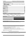

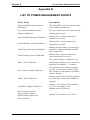


![[ENG] Genibo-SD User Manual Ver.1.0](http://vs1.manualzilla.com/store/data/006872773_1-9d5625b8ce4c775096d8fc2cc6d1600e-150x150.png)