1
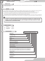
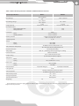
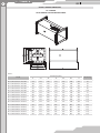
USER’S MANUAL
KP, PL
Fire-Resisting Duct Damper
KP, PL
2
Contents
Safety Requirements
Introduction
Purpose
Delivery Package
Designation Key
Technical Specifications
Design and Operating Principle
Installation and Setup
Connection to Power Mains
Technical Maintenance
Storage and Transportation Regulations
Manufacturer's Warranty
Recycling
Acceptance Certificate
Seller Information
Installation Certificate
Warranty Card
3
4
4
4
4
5
14
15
19
19
19
20
20
21
21
21
22
www.ventilation-system.com
3
Safety Requirements
•
•
•
•
•
•
Read the User's Manual carefully prior to operating and installing the fire-safety damper (hereinafter "Damper").
Installation and operation of the unit must be performed in accordance with the present User's Manual as well as the provisions
of all the applicable local and national construction, electrical and technical codes and standards.
The warnings contained in the present User's Manual must be considered most seriously since they contain vital personal safety
information.
Failure to follow the safety regulations may result in an injury or damper damage.
Upon familiarization keep the User's Manual for the entire service life of the damper.
While transferring equipment control the User's Manual must be turned over to the receiving operator.
The symbols used in the present User's Manual have the following meanings:
ATTENTION!
RESTRICTIONS
Safety precautions to be followed while installing the damper
The damper must be disconnected from the
power mains prior to installation or repair.
Do not use damaged equipment or
conductors to connect the damper to the
power mains.
While installing the damper follow the safety
regulations specific to the use of power tools.
Unpack the damper with care.
Do not change the power cable length at your
own discretion.
Do not bend the power cable.
Avoid damaging the power cable.
Do not position any heating devices or other
equipment in close proximity to the damper
power cable.
Safety precautions to be followed while operating the damper
Avoid damaging the power cable while
operating the damper.
Do not put any foreign objects on top of the
power cable.
Kg
Do not wash the damper with water.
Avoid penetration of water onto the electric
parts of the damper.
ON
Do not sit on the damper or put any foreign
objects on top of it.
Disconnect the damper from the power
mains prior to any technical maintenance.
OFF
Should the damper generate any unusual
sounds, smells or smoke disconnect it from the
power mains and contact the service centre.
Check the damper for secure installation
from time to time in case of prolonged
operation.
KP, PL
4
Introduction
The present operation manual consisting of technical details, operating instructions and technical specification applies to KP and PL
fire-resisting duct dampers.
Purpose
The normally open fire-resisting duct dampers are designed to block the spread of fire and combustion products through the
ventilation and air-conditioning ducts, channels and shafts of various-purpose buildings, spaces and structures.
The KP dampers are compatible with square and rectangular air ducts whereas the PL dampers are designed for round ones.
The dampers is designed for extended periods of continuous operation without disconnection from the power mains.
Being a component unit, the dampers may not be commissioned for standalone operation.
The handled air must not contain flammable or explosive mixtures, chemically active vapours, coarse dust, soot, fats or environments
favourable for the formation of hazardous substances (toxic substances, dust, pathogenic germs), sticky substances and fibrous materials.
The damper is not intended for operation by children or persons with reduced physical, mental or sensory
capacities, or lacking the appropriate training. The damper must be handled only by properly qualified
personnel after the appropriate briefing. The choice of damper installation location must prevent
unauthorized access by unattended children.
Delivery Package
Damper
User's Manual
Shipping Box
Hex Wrench
— 1 piece
— 1 piece
— 1 piece
— 1 piece
DESIGNATION KEY
KP-Х-Х-Х-ХхХ-Х-Х-Х-Х-X
Unit Designation
KP - Fire-Resisting Damper, for Square and Rectangular
Ventilation Ducts
Fire Resistance, hours
1, 2.
Purpose
O − Fire-Resisting
Version
N - General-Purpose Industrial
Damper Flow Area Width, mm
200, 250, 300, 400, 500, 600, 800, 1000.
Damper Flow Area Height, mm
200, 250, 300, 400, 500, 600, 800, 1000.
Number of Flanges
1, 2.
Actuation Mechanism
72S − Thermal Link and Return Spring (Manual Actuation);
BLF24-Т - Electric Actuator with Return Spring and Thermal Sensor; Belimo BLF24-T;
BF24-Т- Electric Actuator with Return Spring and Thermal Sensor; BelimoBF24-T;
BLF230-Т- Electric Actuator with Return Spring and Thermal Sensor; BelimoBLF230-Т;
BF230-Т- Electric Actuator with Return Spring and Thermal Sensor; BelimoBF230-T.
Actuator Position
VN - Internal;
SN - External.
Protective Grille
S − Vandal-Proof Mesh;
R - Decorative Grille;
O - No Grille.
Design Variant
1 - Light-Weight Damper Version;
www.ventilation-system.com
5
PL-10 - Х- DNX/X
Unit Designation
PL-10 - Fire-Safety Damper for Round Ventilation Ducts
Actuator Type
1А − Thermal Link (72 °C), Return Spring (manual actuation);
2-BLF230-Т − Electric Actuator (with Return Spring and Thermal Sensor);
2-BLF24-Т − Electric Actuator (with Return Spring and Thermal Sensor).
Nominal Damper Diameter [mm]
100, 125, 150, 160, 180, 200, 250, 315.
Fire Resistance
EI 120 − 2 hours;
EI 60 − 1 hour.
TECHNICAL SPECIFICATIONS
The dampers are designed for operation in spaces with non-aggressive environment, the air temperature ranging from -30°C to +45°C
and relative humidity up to 80%.
The dampers are compliant with IP X4 standard (hazardous parts access and water ingress protection).
In terms of electric shock hazard the products belong to the following categories of electrical appliances:
• Class III (low voltage) for the dampers with 24 V electric actuator power supply;
• Class II (complete insulation) for the dampers with 230 V electric actuator power supply.
The dampers may not be integrated:
Into air ducts and on premises rated explosion and fire safety category A and B;
Into air ducts of local intakes for flammable and explosive mixtures;
Into systems which do not undergo periodic cleaning pursuant to an approved schedule to prevent the build-up of combustible
deposits.
The damper undergoes continuous improvement. Therefore, some models may slightly differ from the ones described herein.
KP, PL
6
TECHNICAL SPECIFICATIONS: ELECTRIC ACTUATORS
Table 1. Main Technical Specifications of BLF24-T and BLF230-T Electric Actuators
Technical Specifications
BLF24-T
BLF230-T
Rated Voltage
24 V~ 50/60 Hz
24=
230 V~ 50/60 Hz
Rated Voltage Range
19,2…28,8 V~
21,6…28,8 V=
198…264 V~
7 VА
I max 5,8 А at t = 5 ms
7 VА
I max 150 mА at t = 10 ms
5W
2,5 W
6W
3W
Design Capacity
Rated Power Input
During Motor Operation
During Retention
Connection
Cable:
1 m, 2 х 0,75 mm2
1 m, 6 х 0,75 mm2
Power
Auxiliary Switches
Auxiliary Switches
2 single-pole with double switching
1 mА…3 A (0,5 A), 5 V=…250 V~
5° , 80°
- Switching Points
Torque:
Motor
Spring
Switch Actuation Temperature
min. 6 Nm
min. 4 Nm
Tf1: Outside Air Duct Temperature 72 °C
Tf2+ Tf3: Inside Air Duct Temperature 72 °C
Rotational Direction
Swing Angle
Selected by L/R Setting
Max. 95° , (including 5° of factory spring pre-cocking)
Position Indication
Mechanical Pointer
Via a 12 mm Transmission Link
(10 mm with the optional adapter)
Damper Swing
Swing Time:
Noise Level:
Motor
Spring
40…75 с (0…6 Nm)
≈20 s at –20…+50 °С / max. 60 s at –30 °С
Motor
Spring
max 45 dB(А)
≈62 dB(А)
Protection Class
III (for low voltages)
Casing IP Code
Safe Temperature
II (complete insulation)
IP 54
The flap assumes the protective position
at ambient temperatures above +75° C
Ambient Temperature
–30° ... +50 °C
Storage Temperature
–40° ... +50 °C
Technical Maintenance
Weight [kg]
Not Required
1,6
1,7
www.ventilation-system.com
7
Table 2. Main Technical Specifications of BLF24-T and BLF230-T Electric Actuators
Technical Specifications
BF24-T
BF230-T
Rated Voltage
24 V~ 50/60 Hz
24=
230 V~ 50/60 Hz
Rated Voltage Range
19,2…28,8 V~
21,6…28,8 V=
198…264 V~
10 VА
I max 8,3 А at t = 5 ms
12,5 VА
I max 500 mА at t = 5 ms
7W
2W
8W
3W
Design Capacity
Rated Power Input
During Motor Operation
During Retention
Connection
Cable:
1 m, 2 х 0,75 mm2
1 m, 6 х 0,75 mm2
Power
Auxiliary Switches
Auxiliary Switches
2 single-pole with double switching
1 mА…6 A (3 A), 5 V=…250 V~
5° , 80°
- Switching Points
Torque:
Motor
Spring
Switch Actuation Temperature
min 18 Nm
min 12 Nm
Tf1: Outside Air Duct Temperature 72°C
Tf2 + Tf3: Inside Air Duct Temperature 72°C
Rotational Direction
Swing Angle
Selected by L/R Setting
Max. 95° , (including 5° of factory spring pre-cocking)
Position Indication
Mechanical Pointer
Via a 12 mm Transmission Link
(10 mm with the optional adapter)
Damper Swing
Swing Time:
Noise Level:
Motor
Spring
140 s
≈16 s (at ambient t° = 20 °С)
Motor
Spring
Макс. 45 dB(А)
≈62 dB(А)
Protection Class
III (for low voltages)
Casing IP Code
Safe Temperature
II (complete insulation)
IP 54
The flap assumes the protective position
at ambient temperatures above +75° C
Ambient Temperature
–30° ... +50 °C
Storage Temperature
–40° ... +50 °C
Technical Maintenance
Not Required
Weight [kg]
2,8
3,1
The manufacturer reserves the right to equip the dampers with various actuators at its own discretion as long as it does not affect their
original technical parameters.
KP, PL
8
Overall Damper Dimensions
В2
В1
В
KP-1 Damper
with Thermal Link and Return Spring
А
А1
H
А2
Table 3.
Model
Dimensions [mm]
Weight [kg]
A
A1
A2
B
B1
B2
H
KP-1-0-N-200x200-2-72S-SN-0
200
220
240
200
220
240
350
7,5
KP-1-0-N-250x200-2-72S-SN-0
250
270
290
200
220
240
350
8,1
KP-1-0-N-250x250-2-72S-SN-0
250
270
290
250
270
290
350
8,7
KP-1-0-N-300x200-2-72S-SN-0
300
320
340
200
220
240
350
8,6
KP-1-0-N-300x250-2-72S-SN-0
300
320
340
250
270
290
350
9,34
KP-1-0-N-300x300-2-72S-SN-0
300
320
340
300
320
340
350
10
KP-1-0-N-400x250-2-72S-SN-0
400
420
440
250
270
290
350
10,6
KP-1-0-N-400x300-2-72S-SN-0
400
420
440
300
320
340
350
11,3
KP-1-0-N-400x400-2-72S-SN-0
400
420
440
400
420
440
350
12,8
KP-1-0-N-500x300-2-72S-SN-0
500
520
540
300
320
340
350
12,6
KP-1-0-N-500x400-2-72S-SN-0
500
520
540
400
420
440
350
14,2
KP-1-0-N-500x500-2-72S-SN-0
500
530
560
500
530
560
350
15,9
KP-1-0-N-600x400-2-72S-SN-0
600
620
640
400
420
440
350
15,7
KP-1-0-N-600x500-2-72S-SN-0
600
630
660
500
530
560
350
17,5
KP-1-0-N-600x600-2-72S-SN-0
600
630
660
600
630
660
350
19,2
www.ventilation-system.com
9
В2
В1
В
KP-1 Damper
with Electrical Actuator
А
А1
А2
А3
Table 4.
H
Dimensions [mm]
A
A1
A2
A3
B
B1
B2
H
Weight
[kg]
KP-1-O-N-200x200-2-BLF230-T-SN-О
200
220
240
340
200
220
240
350
7,5
KP-1-O-N-250x200-2-BLF230-T-SN-О
250
270
290
390
200
220
240
350
8,1
Model
KP-1-O-N-250x250-2-BLF230-T-SN-О
250
270
290
390
250
270
290
350
8,7
KP-1-O-N-300x200-2-BLF230-T-SN-О
300
320
340
440
200
220
240
350
8,6
KP-1-O-N-300x250-2-BLF230-T-SN-О
300
320
340
440
250
270
290
350
9,34
KP-1-O-N-300x300-2-BLF230-T-SN-О
300
320
340
440
300
320
340
350
10
KP-1-O-N-400x250-2-BLF230-T-SN-О
400
420
440
540
250
270
290
350
10,6
KP-1-O-N-400x300-2-BLF230-T-SN-О
400
420
440
540
300
320
340
350
11,3
KP-1-O-N-400x400-2-BLF230-T-SN-О
400
420
440
540
400
420
440
350
12,8
KP-1-O-N-500x300-2-BLF230-T-SN-О
500
520
540
640
300
320
340
350
12,6
KP-1-O-N-500x400-2-BLF230-T-SN-О
500
520
540
640
400
420
440
350
14,2
KP-1-О-Н-500x500-2-BF230-T-SN-О
500
530
560
650
500
530
560
350
15,9
KP-1-O-N-600x400-2-BLF230-T-SN-О
600
620
640
740
400
420
440
350
15,7
KP-1-О-N-600x500-2-BF230-T-SN-О
600
630
660
750
500
530
560
350
17,5
KP-1-О-N-600x600-2-BF230-T-SN-О
600
630
660
750
600
630
660
350
19,2
KP-1-О-N-800x500-2-BF230-T-SN-О
800
830
860
950
500
530
560
350
20,6
KP-1-О-N-800x600-2-BF230-T-SN-О
800
830
860
950
600
630
660
350
22,6
KP-1-О-N-800x800-2-BF230-T-SN-О
800
830
860
950
800
830
860
350
26,6
KP-1-О-N-1000x600-2-BF230-T-SN-О
1000
1030
1060
1150
600
630
660
350
26
KP-1-О-N-1000x800-2-BF230-T-SN-О
1000
1030
1060
1150
800
830
860
350
30,6
KP-1-О-N-1000x1000-2-BF230-T-SN-О
1000
1030
1060
1150
1000
1030
1060
350
36,4
Note: The table values for the dampers equipped with BF230-T/BLF230-T actuators are identical to those equipped with BF24-T/BLF24-T
actuators.
KP, PL
10
В2
В1
В
KP-2 Damper
with Thermal Link and Return Spring
А
А1
А2
H
А3
Table 5.
Model
Dimensions [mm]
A
A1
A2
A3
B
B1
B2
H
Weight
[kg]
KP-2-0-N-200x200-2-72S-SN-0
200
220
280
313,5
200
220
280
380
10
KP-2-0-N-250x200-2-72S-SN-0
250
270
330
363,5
200
220
280
380
11
KP-2-0-N-300x200-2-72S-SN-0
300
320
380
413,5
200
220
280
380
12
KP-2-0-N-250x250-2-72S-SN-0
250
270
330
363,5
250
270
330
380
12,1
KP-2-0-N-300x250-2-72S-SN-0
300
320
380
413,5
250
270
330
380
13,25
KP-2-0-N-400x250-2-72S-SN-0
400
420
480
513,5
250
270
330
380
15,5
KP-2-0-N-300x300-2-72S-SN-0
300
320
380
413,5
300
320
380
380
14,5
KP-2-0-N-400x300-2-72S-SN-0
400
420
480
513,5
300
320
380
380
16,9
KP-2-0-N-500x300-2-72S-SN-0
500
520
580
613,5
300
320
380
380
19,4
KP-2-0-N-400x400-2-72S-SN-0
400
420
480
513,5
400
420
480
380
19,9
KP-2-0-N-500x400-2-72S-SN-0
500
520
580
613,5
400
420
480
380
22,7
KP-2-0-N-600x400-2-72S-SN-0
600
620
680
713,5
400
420
480
380
25,5
KP-2-0-N-500x500-2-72S-SN-0
500
520
580
613,5
500
520
580
380
27,8
KP-2-0-N-600x500-2-72S-SN-0
600
620
680
713,5
500
520
580
380
31,25
KP-2-0-N-600x600-2-72S-SN-0
600
620
680
713,5
500
640
580
380
35
www.ventilation-system.com
11
KP-2 Damper
with Electrical Actuator
В2
В1
В
А2
А
А1
А3
H
Table 6.
Dimensions [mm]
A
A1
A2
A3
B
B1
B2
H
Weight
[kg]
KP-2-O-N-200x200-2-BLF230-T-SN-О
200
220
280
322,5
200
220
280
380
10,75
KP-2-O-N-250x200-2-BLF230-T-SN-О
250
270
280
372,5
200
220
280
380
11,6
Model
KP-2-O-N-300x200-2-BLF230-T-SN-О
300
320
280
422,5
200
220
280
380
12,45
KP-2-O-N-250x250-2-BLF230-T-SN-О
250
270
330
372,5
250
270
330
380
12,5
KP-2-O-N-300x250-2-BLF230-T-SN-О
300
320
380
422,5
250
270
330
380
13,4
KP-2-O-N-400x250-2-BLF230-T-SN-О
400
420
480
522,5
250
270
330
380
15,2
KP-2-O-N-300x300-2-BLF230-T-SN-О
300
320
380
422,5
300
320
380
380
14,3
KP-2-O-N-400x300-2-BLF230-T-SN-О
400
420
480
522,5
300
320
380
380
16,2
KP-2-O-N-500x300-2-BLF230-T-SN-О
500
520
580
622,5
300
320
380
380
18,1
KP-2-O-N-400x400-2-BLF230-T-SN-О
400
420
480
522,5
400
420
480
380
18,3
KP-2-O-N-500x400-2-BLF230-T-SN-О
500
520
580
622,5
400
420
480
380
20,4
KP-2-O-N-600x400-2-BLF230-T-SN-О
600
620
680
722,5
400
420
480
380
22,5
KP-2-О-Н-500x500-2-BF230-T-SN-О
500
520
580
622,5
500
520
580
380
22,6
KP-2-О-N-600x500-2-BF230-T-SN-О
600
620
680
722,5
500
520
580
380
25
KP-2-О-N-800x500-2-BF230-T-SN-О
800
820
880
922,5
500
520
580
380
29,5
KP-2-О-N-600x600-2-BF230-T-SN-О
600
620
680
722,5
600
620
680
380
27,4
KP-2-О-N-800x600-2-BF230-T-SN-О
800
820
880
922,5
600
620
680
380
32,4
KP-2-О-N-1000x600-2-BF230-T-SN-О
1000
1020
1080
1122,5
600
620
680
380
37,2
KP-2-О-N-800x800-2-BF230-T-SN-О
800
820
880
922,5
800
820
880
380
38,1
KP-2-О-N-1000x800-2-BF230-T-SN-О
1000
1020
1080
1122,5
800
820
880
380
43,9
KP-2-О-N-1000x1000-2-BF230-T-SN-О
1000
1020
1080
1122,5
1000
1020
1080
380
52,2
Note: The table values for the dampers equipped with BF230-T/BLF230-T actuators are identical to those equipped with BF24-T/BLF24-T
actuators.
KP, PL
12
В
В1
В2
KP-2-1 Damper
with Electrical Actuator
А
А1
А2
H
А3
Table 7.
Model
Dimensions [mm]
Weight
[kg]
A
A1
A2
A3
B
B1
B2
H
KP-2-O-N-200x200-2-BLF230-T-SN-О-1
200
220
240
340
200
220
240
350
9,5
KP-2-O-N-250x200-2-BLF230-T-SN-О-1
250
270
290
390
200
220
240
350
10,0
KP-2-O-N-250x250-2-BLF230-T-SN-О-1
250
270
290
390
250
270
290
350
11,5
KP-2-O-N-300x200-2-BLF230-T-SN-О-1
300
320
340
440
200
220
240
350
11,45
KP-2-O-N-300x250-2-BLF230-T-SN-О-1
300
320
340
440
250
270
290
350
11,95
KP-2-O-N-300x300-2-BLF230-T-SN-О-1
300
320
340
440
300
320
340
350
12,8
KP-2-O-N-400x250-2-BLF230-T-SN-О-1
400
420
440
540
250
270
290
350
13,7
KP-2-O-N-400x300-2-BLF230-T-SN-О-1
400
420
440
540
300
320
340
350
14,7
KP-2-O-N-400x400-2-BLF230-T-SN-О-1
400
420
440
540
400
420
440
350
16,8
KP-2-O-N-500x300-2-BLF230-T-SN-О-1
500
520
540
640
300
320
340
350
16,6
KP-2-O-N-500x400-2-BLF230-T-SN-О-1
500
520
540
640
400
420
440
350
18,9
KP-2-О-N-500x500-2-BF230-T-SN-О-1
500
530
560
650
500
530
560
350
21,1
KP-2-O-N-600x400-2-BLF230-T-SN-О-1
600
620
640
740
400
420
440
350
21,0
KP-2-О-N-600x500-2-BF230-T-SN-О-1
600
630
660
750
500
530
560
350
23,5
KP-2-О-N-600x600-2-BF230-T-SN-О-1
600
630
660
750
600
630
660
350
25,9
KP-2-О-N-800x500-2-BF230-T-SN-О-1
800
830
860
950
500
530
560
350
28,0
KP-2-О-N-800x600-2-BF230-T-SN-О-1
800
830
860
950
600
630
660
350
30,9
KP-2-О-N-800x800-2-BF230-T-SN-О-1
800
830
860
950
800
830
860
350
36,6
KP-2-О-N-1000x600-2-BF230-T-SN-О-1
1000
1030
1060
1150
600
630
660
350
35,7
KP-2-О-N-1000x800-2-BF230-T-SN-О-1
1000
1030
1060
1150
800
830
860
350
42,4
KP-2-О-N-1000x1000-2-BF230-T-SN-О-1
1000
1030
1060
1150
1000
1030
1060
350
50,7
Note: Thetable values for the dampers equipped with BF230-T/BLF230-T actuators are identical to those equipped with BF24-T/BLF24-T
actuators.
www.ventilation-system.com
13
D
В
PL DAMPER
WITH THERMAL LINK AND RETURN SPRING
L
Table 8.
Model
Dimensions [mm]
Weight [kg]
ØD
L
B
PL-10-1A-DN100
99
170
112
1,0
PL-10-1A-DN125
124
170
137
1,2
PL-10-1A-DN150
149
170
162
1,5
PL-10-1A-DN160
159
170
172
1,6
PL-10-1A-DN180
179
170
192
1,8
PL-10-1A-DN200
199
170
212
2,0
PL-10-1A-DN250
249
190
262
2,5
PL-10-1A-DN315
314
190
327
3,3
D
PL DAMPER
WITH ELECTRIC ACTUATOR, RETURN SPRING AND
THERMALLY SENSITIVE BREAKER
L
B
Table 9.
Model
Dimensions [mm]
Weight [kg]
ØD
L
B
PL-10-2-BLF230-T (BLF24-T)-DN100
99
300
185
2,9
PL-10-2-BLF230-T (BLF24-T)-DN125
124
300
205
3,1
PL-10-2-BLF230-T (BLF24-T)-DN150
149
300
240
3,4
PL-10-2-BLF230-T (BLF24-T)-DN160
159
300
245
3,5
PL-10-2-BLF230-T (BLF24-T)-DN180
179
300
255
3,8
PL-10-2-BLF230-T (BLF24-T)-DN200
199
300
265
4,0
PL-10-2-BLF230-T (BLF24-T)-DN250
249
310
290
4,7
PL-10-2-BLF230-T (BLF24-T)-DN315
314
310
340
5,6
KP, PL
14
KP Damper Design
DESIGN AND OPERATING PRINCIPLE
1
Damper Components:
1 - Hot and Cold Zone Baffle;
2 - Galvanized Casing;
3 - Fire-Proof Material Damper;
4 - Thermally Sensitive Breaker;
5 - Electric Actuator;
6 - Return Spring Mechanism Handle;
7 - Thermal Link (manually actuated dampers);
The hot and cold zone baffle (1) is absent in the KP1, PL1… EI60
(single-hour) series dampers.
The damper actuates in the event of fire shutting off the air
duct. The damper is closed by an electric actuator triggered by an
electric signal from a temperature transducer. The damper can also
actuate upon a closing signal from a fire-protection switchboard
after the fuse has burnt out.
PL Damper Design
2
3
6
7
Manually Actuated Damper with Thermal Link for Square
and Rectangular Ducts.
1
1
2
2
3
4
3
7
5
6
Manually Actuated Damper with Thermal Link and Return
Spring for Round Ducts.
1
2
Electrically Actuated Dampers for Square and
Rectangular Ducts.
2
7
3
3
4
6
5
Electrically Actuated Damper for Round Ducts.
Manually Actuated Damper with Thermal Link and Return
Spring for Square and Rectangular Ducts.
www.ventilation-system.com
15
Installation and Pre-Operation Setup
The dampers are installed into square or rectangular (KP series) and round (PL series) air ducts of ventilation systems, and the
apertures of ventilation shafts, division walls and fire partitions.
The installation of the dampers into ventilation systems must be carried out in consideration of the air flow direction.
While installing electrically actuated dampers provide for sufficient space for the actuator inspection.
• When preparing the fire-safety dampers for installation the damper casing must be fitted with wooden spreader bars to prevent
deformation, torsional twisting or geometry perturbation of the casing which may result in flap jamming and, eventually, loss of
the damper functionality.
• Following the damper installation into the shaft, wall or ceiling filler structure section and upon complete curing (immobilization)
of the mortar make sure to remove the wooden spreader bars. The damper must open and close freely without excessive friction.
• To install the dampers into the apertures of wall or ceiling slabs fill up the gaps between the damper casing and the aperture. The
gaps are filled with fire-resistant mortar.
• The damper design enables its attachment to air ducts and other ventilation system components by means of flanges as well as
its installation into filler structures. Under any installation scenario the mating structure fire-resistance level must be upgraded by
using extra fire insulation to at least match that of the filler structure of the respective fire-safety zone.
KP Damper Installation
The dampers can be installed in any position into vertical and horizontal channels of fire-protection structures. The damper installation
openings must be made in such a way so as to prevent the transfer of loads caused by the fire-protection structures to the damper casing.
The adjoining air duct must be suspended in such a way so as to prevent the transfer of air duct load to the damper flange. There must
be at least 350 mm of unrestricted clearance for accessing the control elements. Make sure to arrange an inspection hole. While carrying
out the installation mind size К. When two or more dampers are installed into the same fire-protection separation structure the distance
between the two adjacent dampers must be at least 200 mm.
The damper must be installed in such a way that the damper flap lies in the fire-protection divider structure plane while closed. If
such installation is not possible, the damper casing part between the fire-protection separation structure and the damper flap must be
insulated with a suitable material pursuant to the applicable standards.
The damper control mechanism must be protected against damage and contamination. Avoid damper casing deformation during the
embedding. After the installation the flap must not catch against the damper casing while opening or closing.
Fire-safety dampers can be integrated into a tight wall structure - e.g. made of conventional concrete work of minimum width W = 100
mm or into a plasterboard wall of the necessary fire resistance class or into a tight ceiling structure - e.g. made of conventional concrete
of minimum width W = 150 mm.
The recommended values for construction openings are given below.
KP, PL
16
KP-1 Damper with Thermal Link and Return Spring
KP-1 Fire-Resisting Damper with Thermal Link
and Return Spring
Intermediate Layer
W
В+160
В
K
A and B sizes (see Table 3, Page 8)
K
А
А+160
Intermediate Layer
W
Wall (fire separation)
Wall (fire separation)
Ceiling (fire separation)
Insulation
KP-1 Fire-Resisting Damper with Thermal Link
and Return Spring
Intermediate Layer
KP-1 Fire-Resisting Damper with Thermal Link
and Return Spring
KP-1 Damper with Electrical Actuator
Wall (fire separation)
KP-1 Fire-Resisting Damper
with Electrical Actuator
Intermediate
Layer
Intermediate
Layer
270
W
K
A and B sizes (see Table 4, Page 9)
KP-1 Fire-Resisting Damper
with Electrical Actuator
K
W
Ceiling (fire separation)
KP-2 DAMPER WITH THERMAL LINK AND RETURN SPRING
Wall (fire separation)
Intermediate Layer
KP-2 Fire-Resisting Damper
with Thermal Link and Return Spring
KP-2 Fire-Resisting Damper
with Thermal Link and Return Spring
Intermediate Layer
W
В
В+160
K
A and B sizes (see Table 5, Page 10)
Ceiling (fire separation)
А
А+160
K
W
www.ventilation-system.com
17
KP-2 DAMPER WITH ELECTRICAL ACTUATOR
Wall (fire separation)
KP-2 Fire-Resisting Damper
with Electrical Actuator
Intermediate Layer
KP-2 Fire-Resisting Damper
with Electrical Actuator
K
W
В
В+160
Ceiling (fire separation)
А
K
А+160
Intermediate Layer
W
A and B sizes (see Table 6, Page 11)
Wall (fire separation)
Insulation
Intermediate Layer
KP-2 Fire-Resisting Damper
with Electrical Actuator
KP-2-1 DAMPER WITH ELECTRICAL ACTUATOR
KP-2 Fire-Resisting Damper, Light-Weight
Version, with Electrical Actuator
Intermediate Layer
В
В+160
W
K
Wall (fire separation)
Intermediate Layer
А
А+160
Ceiling (fire separation)
K
W
A and B sizes (see Table 7, Page 12)
KP-2 Fire-Resisting Damper, Light-Weight
Version, with Electrical Actuator
KP, PL
18
PL Damper Installation
Fire-safety dampers can be installed into solid walls with the minimum width of W=100 mm, into both round and square apertures,
minimum intermediate layer thickness S=50 mm. The walls can be made of concrete, brick or foam concrete blocks. The intermediate
layer can be made of concrete or mortar. While carrying out the installation mind size К. When installing the dampers into thicker walls
add an extender section on one of the damper sides.
The electric actuator can be positioned freely on either side of the fire control sector (space) wall.
Стена (противопожарная преграда)
Wall (fire separation)
Intermediate Layer
Intermediate Layer
PL-10-2 Fire-Resisting Damper
with Electrical Actuator
S
S
PL-10-1 Fire-Resisting Damper
D
K
D
D+2S
D+2S
W
Size D (see Table on
Page 13)
W
K
Fire-safety dampers can be installed into solid ceiling panels with the minimum thickness of W=150 mm, minimum intermediate layer
thickness S=50 mm. The ceiling panels are made of concrete. The intermediate layer can be made of concrete or mortar. While carrying
out the installation mind size К.
When installing the dampers into thicker walls add an extender section on one of the damper sides.
The electric actuator can be positioned freely above or below the ceiling panel of the fire control sector (space).
Extender Section (if necessary)
Extender Section
(if necessary)
PL-10-1 Fire-Resisting Damper
Intermediate Layer
PL-10-2 Fire-Resisting Damper
with Electrical Actuator
Ceiling Panel (fire separation)
Ceiling Panel (fire separation)
S
K
W
W
S
K
Intermediate Layer
Permissible Positions for Fire-Safety Damper Installation.
The damper axle and actuation mechanism can be installed in any position - from horizontal to vertical.
www.ventilation-system.com
19
POWER MAINS CONNECTION
Connection
via Transformer
DISCONNECT THE DAMPER FROM
THE POWER SUPPLY PRIOR TO
ANY WORK PERFORMED ON THE
UNIT. ANY TAMPERING WITH
THE INTERNAL CONNECTIONS IS
PROHIBITED AND SHALL VOID
THE WARRANTY.
BF24-T, BF230-T
BLF24-T, BLF230-T
1 - Blue Wire
2 - Brown Wire
The actuators featuring a return spring are designed to control fire-resisting dampers and smoke-extraction dampers installed in
ventilation and air-conditioning systems.
The return spring is cocked upon setting the damper flap to the horizontal position. In case of a power failure the damper flap is re-set
to the protective position by the energy stored in the spring.
The damper does not require any limit switches and is overload-proof.
The thermally sensitive breaker Tf1 actuates upon ambient temperature exceeding 72 °C. The renewable thermally sensitive breakers
Tf2 and Tf3 actuate upon the air duct temperature exceeding 72 °C. The operation of the renewable thermally sensitive breakers interrupts
the electric power supply in such a way that it prevents actuator re-activation without their replacement.
The button on the thermally sensitive breaker body enables testing the damper functionality.
The actuator is equipped with two fixed microswitches which signal the end positions.
Intermediate positions of the damper are shown by the mechanical indicator (needle).
The BF24-T and BLF24-T actuators are connected via an insulated transformer unit .
The damper can also be controlled manually and fixed in any position. The unit can be unlocked either manually using a hex wrench
(included) or automatically upon power-up.
The actuator connections (cables and wires) must be durable, insulated and heat-resistant.
The recommended minimum conductor cross-section is 0.75 mm2. The conductor cross-section selection must account for the
maximum permissible wire heating which depends on the wire type, its insulation, length and installation method (i.e. overhead, in cable
channels or inside walls).
TECHNICAL MAINTENANCE
The damper technical maintenance includes routine inspections and functionality checks.
The damper technical maintenance frequency must comply with the established technical maintenance frequency of the fire safety
equipment complex of the facility.
The routine inspections must include repair-and-renewal operations and cleaning the damper internals of any debris as necessary.
The damper functionality is checked by energizing the electric actuator. The damper must close on power-up. The data obtained in the
course of the damper technical maintenance must be entered into the logbook. Combined logbooks may be kept for the entire fire-safety
equipment complex of the facility.
TRANSPORTATION AND STORAGE REGULATIONS
The dampers must be transported fully assembled either separately or in batches. The transportation method must prevent the
dampers from the effects of any significant vibrations or ingress of moisture. The damper must be stored in the original packing in a dry
ventilated area at temperatures from +10 °C to +40 °C. The air in the storage space must not contain any vapours or admixtures which may
lead to corrosion or compromise the insulation and seals. Use only suitable lifting equipment for handling operations to prevent damage
to the damper. Follow the applicable moving regulations specific to the cargo type while loading and unloading. The unit can be carried
in the original packing by any mode of transport without limitation provided proper protection against precipitation and mechanical
damage. Avoid sudden jolts and impacts while transporting or handling the unit.
KP, PL
20
Manufacturer's Warranty
The manufacturer hereby warrants normal operation (service life) of the damper over the period of 24 months from the retail sale date
provided observance of the transportation, storage, installation and operation regulations.
Should any malfunctions occur in the course of the damper operation through the Manufacturer's fault during the guaranteed period of
operation the user is entitled to elimination of faults by the manufacturer by means of warranty repair at the factory carried out free of charge.
The warranty repair shall include work specific to elimination of faults in the damper operation to ensure its intended use by the user
within the guaranteed period of operation. The faults are eliminated by means of replacement or repair of the damper components or a
specific part of such damper component.
The warranty repair does not include:
•
Routine technical maintenance;
•
Damper installation/removal;
•
Damper setup.
To benefit from warranty repair the user must submit the damper, the User's Manual with the sale date stamp and the payment document
certifying the purchase.
The damper model must comply with the one stated in the User's Manual.
Please contact the damper vendor for any matters related to warranty service.
The manufacturer's warranty does not apply to the following cases:
•
User's failure to submit the damper with the entire delivery package as stated in the User's Manual or with missing component parts
previously dismounted by the user;
•
Mismatch of the damper model and make with the respective details stated on the unit packaging and in the User's Manual;
•
User's failure to ensure timely technical maintenance of the damper;
•
External damage to the damper casing (excluding external modifications to the damper as required for installation) and internal
components caused by the user;
•
Alteration of the damper design or engineering changes to the product;
•
Replacement and use of the such damper assemblies, parts and components not approved by the manufacturer;
•
Damper misuse;
•
User's violation of the damper storage regulations;
•
User's violation of the damper operation regulations;
•
Damper connection to the power mains with a voltage different from the one stated in the User's Manual;
•
Damper failure due to voltage surges in the power mains;
•
Discretionary repair of the unit damper the user;
•
Damper repair by any persons without the manufacturer's authorization;
•
Expiration of the damper warranty period;
•
User's violation of the damper transportation regulations;
•
User's violation of the damper storage regulations;
•
Wrongful acts against the damper committed by a third party;
•
Damper failure due to circumstances of insuperable force (fire, flood, earthquake, war, hostilities of any kind, or blockade);
•
Missing seals if provided by the User's Manual;
•
Failure to submit the User's Manual with the damper sale date stamp;
•
Missing payment document certifying the damper purchase.
FOLLOWING THE REGULATIONS STIPULATED HEREIN WILL ENSURE A LONG AND
TROUBLE-FREE OPERATION OF THE DAMPER.
USERS' CLAIMS SHALL BE REVIEWED ONLY UPON PRESENTATION OF THE DAMPER, THE
PAYMENT DOCUMENT AND THE USER'S MANUAL WITH THE SALE DATE STAMP.
Recycling
The damper shall be recycled at the end of its service life. The unit shall be recycled pursuant to the standing norms and standards
which may vary by region.
www.ventilation-system.com
21
Acceptance Certificate
Product Type
Fire-Resisting Duct Damper
Model
Serial Number
Manufacture Date
Is recognized as serviceable.
Quality Inspector's
Stamp
Seller Information
Outlet Name
Address
Phone Number
E-mail
Purchase Date
This is to certify delivery of the complete damper with the User's Manual. The warranty terms are
acknowledged and accepted.
Vendor's Seal
Buyer's Signature
Installation Certificate
This is to certify that ______________________________ Fire-Resisting Duct Damperhas been installed
and connected to the power mains pursuant to the requirements stated in the present User's Manual.
Company Name
Address
Phone Number
Installation
Technician's Full Name
Installation Date:
Signature:
The damper has been installed in accordance with the provisions of all the applicable local and national
construction, electrical and technical codes and standards. The damper operates normally without any
flaws.
Signature:
Installation Technician's
Company Seal
KP, PL
22
Warranty Card
Product Type
Fire-Resisting Duct Damper
Model
Serial Number
Manufacture Date
Purchase Date
Warranty Period
Vendor Company
Vendor's Seal
______________________________________________________________________________________________________
______________________________________________________________________________________________________
______________________________________________________________________________________________________
______________________________________________________________________________________________________
______________________________________________________________________________________________________
______________________________________________________________________________________________________
______________________________________________________________________________________________________
_________________________________________________________________________________________________
Notes
_____________________________________________________________________________________
_____________________________________________________________________________________
_____________________________________________________________________________________
_____________________________________________________________________________________
_____________________________________________________________________________________
_____________________________________________________________________________________
_____________________________________________________________________________________
_____________________________________________________________________________________
_____________________________________________________________________________________
_____________________________________________________________________________________
_____________________________________________________________________________________
_____________________________________________________________________________________
_____________________________________________________________________________________
_____________________________________________________________________________________
_____________________________________________________________________________________
_____________________________________________________________________________________
_____________________________________________________________________________________
_____________________________________________________________________________________
_____________________________________________________________________________________
_____________________________________________________________________________________
_____________________________________________________________________________________
_____________________________________________________________________________________
www.ventilation-system.com
23
V58-1EN-01