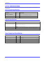
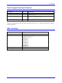
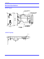
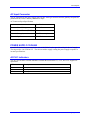
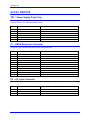
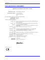
1
Looking for more information?
Visit us on the web at http://www.artisan-scientific.com for more information:
• Price Quotations • Drivers· Technical Specifications. Manuals and Documentation
Artisan Scientific is You~ Source for: Quality New and Certified-Used/Pre:-awned ECJuiflment
• Fast Shipping and DelIve1y
• Tens of Thousands of In-Stock Items
• Equipment Demos
• Hundreds of Manufacturers Supported
• Leasing / Monthly Rentals
Service Center Repairs
Experienced Engineers and Technicians on staff in our
State-of-the-art Full-Service In-House Service Center Facility
• Consignment
InstraView Remote Inspection
Remotely inspect equipment before purchasing with our
Innovative InstraView-website at http://www.instraview.com
We bUy used equipment! We also offer credit for Buy-Backs and Trade-Ins
Sell your excess. underutilized. and idle used equipment. Contact one of our Customer Service Representatives todayl
Talk to a live person: 88EM38-S0URCE fB88-887-68721 I Contact us by email: [email protected] I Visit our website: http://www.artisan-scientific.com
^1 USER MANUAL
^2 Accessory E1
^3 UMAC POWER SUPPLY
^4 31E-603269-10x
^5 July 7, 2006
Copyright Information
Single Source Machine Control
Power // Flexibility // Ease of Use
21314 Lassen Street Chatsworth, CA 91311 // Tel. (818) 998-2095 Fax. (818) 998-7807 // www.deltatau.com
© 2006 Delta Tau Data Systems, Inc. All rights reserved.
This document is furnished for the customers of Delta Tau Data Systems, Inc. Other uses are
unauthorized without written permission of Delta Tau Data Systems, Inc. Information contained
in this manual may be updated from time-to-time due to product improvements, etc., and may not
conform in every respect to former issues.
To report errors or inconsistencies, call or email:
Delta Tau Data Systems, Inc. Technical Support
Phone: (818) 717-5656
Fax: (818) 998-7807
Email: [email protected]
Website: http://www.deltatau.com
Operating Conditions
All Delta Tau Data Systems, Inc. motion controller products, accessories, and amplifiers contain
static sensitive components that can be damaged by incorrect handling. When installing or
handling Delta Tau Data Systems, Inc. products, avoid contact with highly insulated materials.
Only qualified personnel should be allowed to handle this equipment.
In the case of industrial applications, we expect our products to be protected from hazardous or
conductive materials and/or environments that could cause harm to the controller by damaging
components or causing electrical shorts. When our products are used in an industrial
environment, install them into an industrial electrical cabinet or industrial PC to protect them
from excessive or corrosive moisture, abnormal ambient temperatures, and conductive materials.
If Delta Tau Data Systems, Inc. products are directly exposed to hazardous or conductive
materials and/or environments, we cannot guarantee their operation.
REVISION HISTORY
REV.
DESCRIPTION
DATE
CHG
APPVD
1
ADDED CE DECLARATION
06/08/06
CP
S.FIERRO
2
MARKED FOR FULL RELEASE
07/07/06
CP
S.FIERRO
Accessory E1
Table of Contents
INTRODUCTION .....................................................................................................................................................1
SAFETY INSTRUCTIONS ......................................................................................................................................3
Power Disconnect....................................................................................................................................................3
ACC-E1 SPECIFICATIONS ...................................................................................................................................5
Environmental Specifications..................................................................................................................................5
Physical Specifications............................................................................................................................................5
Power Supply Input Specifications .........................................................................................................................5
Power Supply Output Specifications.......................................................................................................................6
EMC and Safety ......................................................................................................................................................6
Mechanical Specifications.......................................................................................................................................7
ACC-E1 Layout...................................................................................................................................................7
AC Input Connector ................................................................................................................................................8
POWER SUPPLY COOLING ................................................................................................................................8
ACC-E1 Indicators..................................................................................................................................................8
ACC-E1 PINOUTS....................................................................................................................................................9
TB1 – Power Supply Output Tap............................................................................................................................9
P1 – UBUS Backplane Connector ..........................................................................................................................9
P2 – AC Input Connector........................................................................................................................................9
DECLARATION OF CONFORMITY .................................................................................................................11
Table of Contents
i
Accessory E1
INTRODUCTION
The ACC-E1 power supply module is an accessory card that provides the UMAC backplane with system
operating power.
This ACC-E1 has an AC input connector to the switching power supply and provides DC outputs to the
UMAC control system via the UBUS backplane. The ACC-E1 also has a terminal block connector that
provides the regulated +5Vdc and ±15Vdc that can be used for general purpose DC power to other
components in the system
The ACC-E1 power supply also comes pre-configured for remote voltage sense on the 5Vdc bus: A
function that has been installed on the UMAC backplanes since their inception. LED’s on the front panel
indicate the presence of +5Vdc, +15Vdc, and –15Vdc.
The ACC-E1 power supply consists of a commercially available power supply mounted to a motherboard
that connects the DC power to the UBUS backplane board.
Introduction
1
Accessory E1
2
Introduction
Accessory E1
SAFETY INSTRUCTIONS
Qualified personnel must transport, assemble, install, and maintain this equipment. Properly qualified
personnel are persons who are familiar with the transport, assembly, installation, and operation of
equipment. The qualified personnel must know and observe the following standards and regulations:
IEC 364 resp. CENELEC HD 384 or DIN VDE 0100
IEC report 664 or DIN VDE 0110
National regulations for safety and accident prevention or VBG 4
Incorrect handling of products can result in injury and damage to persons and machinery. Strictly adhere
to the installation instructions. Electrical safety is provided through a low-resistance earth connection. It
is vital to ensure that all system components are connected to earth ground.
This product contains components that are sensitive to static electricity and can be damaged by incorrect
handling. Avoid contact with high insulating materials (artificial fabrics, plastic film, etc.). Place the
product on a conductive surface. Discharge any possible static electricity build-up by touching an
unpainted, metal, grounded surface before touching the equipment.
Keep all covers and cabinet doors shut during operation. Be aware that during operation, the product has
electrically charged components and hot surfaces. Control and power cables can carry a high voltage,
even when the motor is not rotating. Never disconnect or connect the product while the power source is
energized to avoid electric arcing.
After removing the power source from the equipment, wait at least 10 minutes before touching or
disconnecting sections of the equipment that normally carry electrical charges (e.g., capacitors, contacts,
screw connections). To be safe, measure the electrical contact points with a meter before touching the
equipment.
The following text formats are used in this manual to indicate a potential for personal injury or equipment
damage. Read the safety notices in this manual before attempting installation, operation, or maintenance
to avoid serious bodily injury, damage to the equipment, or operational difficulty.
WARNING:
A Warning identifies hazards that could result in personal injury or death. It
precedes the discussion of interest.
Caution:
A Caution identifies hazards that could result in equipment damage. It precedes the
discussion of interest
Note:
A Note identifies information critical to the user’s understanding or use of the
equipment. It follows the discussion of interest.
Power Disconnect
A power disconnect should be installed by the user between the input power service and the ACC-E1
power supply for a fail–safe method to disconnect power.
Safety Instructions
3
Accessory E1
4
Safety Instructions
Accessory E1
ACC-E1 SPECIFICATIONS
Please note that these are design specifications. Performance may differ slightly from these design
specifications.
Environmental Specifications
Description
Unit
Specification
Operating Temperature
ºC
Storage Temperature
Humidity
ºC
%
0°C to 45°C,
41°C to 70°C derate to 50%
-25°C to 70°C
10% to 95 % non-condensing
Physical Specifications
Item
Specification
Dimensions
Length: 16.256 cm
(6.4 in.)
Height: 10 cm (3.94 in.)
Width: 6.1
cm (2.4 in.)
480g
Weight (max)
MSTBW 1.5/6-G-5.08 from Phoenix Contact UL 94V-0 rating
Terminal Block
The width is the width of the front plate. The length and height are the dimensions of the PCB.
Power Supply Input Specifications
Description
Unit
Specification
AC Input
V
Power Supply Efficiency
Input Frequency
Input Current Max
Inrush Current
%
Hz
Arms
A
100V to 120V and 200V to 240V (autoranging)
82%
Specifications
50 Hz to 60 Hz
2.9 Arms
40A
5
Accessory E1
Power Supply Output Specifications
Description
Unit
Specification
Power Output
W
DC Output
A
80W without fan
130W with fan
+5V @ 14A with fan
+16.3V @ 1.5A with fan
-16.3V @ 1.5A with fan
Overload Protection
W
195W, +35W
The power supply has an in line slow-blow fuse rated at 250V @ 3.5A. If this fuse fails, please send unit
back to Delta Tau.
EMC and Safety
Item
Description
CE Mark
EMC
Full Compliance
Safety
Flammability Class
6
EN55011 Class A Group 1
EN61000-3-2 Class A
EN61000-3-3
EN61000-4-2
EN61000-4-3
EN61000-4-4
EN61000-4-5
EN61000-4-6
EN61000-4-11
EN 61010-1
UL 94V-0
Specifications
Accessory E1
Mechanical Specifications
ACC-E1 Layout
TB2
TB1
AC CABLE
J3
8
1
J2
16 AWG WIRE
6
2
1
P2
FACEPLATE
3 SLOT
ACC-E1 Top View
Pin 1
Specifications
7
Accessory E1
AC Input Connector
The AC input plug on the power supply unit is an IEC male type meant to meet the globally accepted IEC
publication 320, Class 1 industry standard AC input.
AC Connector Input Specifications
Item
Specification
Connector Rated Voltage
250 VAC
Connector Rated Current (UL/CSA)
15A
Dielectric Strength (one minute)
2000V between pins
Flammability Class
UL 94V-0
POWER SUPPLY COOLING
A small 12V fan has been mounted to the side of the UMAC rack to provide cooling for the AC supply.
The fan provides 14.0 CFM at 12V. The fan is needed to supply cooling the power supply to operate at
its rated specifications.
ACC-E1 Indicators
The ACC-E1 has three red LED indicators to inform the user that the 5V, +15V, and –15V supplies are
operational.
LED
Description
D1
D2
D3
+5V power indicator
+15V power indicator
-15V power indicator
8
Specifications
Accessory E1
ACC-E1 PINOUTS
TB1 – Power Supply Output Tap
This is a 6 pin Phoenix Combicon connector. This is a supply output connector which has 10A rated
Contacts and has a UL 94V0 flammability rating.
PIN#
Name
Description
1
2
3
4
5
6
+15V dc
+5V dc
+5V dc
AGND
GND
-15V dc
+15V DC Power
+5V DC Power
+5V DC Power
0V Reference for ± 15V
0V Reference for +5V
-15V DC Power
P1 – UBUS Backplane Connector
This is an 11-pin connector that plugs into the UBUS backplane
PIN#
Name
Description
2
5
8
11
14
17
20
23
26
29
32
Chassis GND
SenseSense+
Spare
GND
+5V
-15V
+15V
AGND
+5V
GND
Chassis GND
5V DC Sense- input
5V DC Sense+ input
0V reference for 5V
+5V DC Power
-15V DC Power
+15V DC Power
0V Reference for ± 15V
+5V DC Power
0V reference for 5V
P2 – AC Input Connector
This is an IEC 3-pin AC connector providing power to the power supply.
PIN#
Name
Description
1
2
3
Line
Chasis Ground
Neutral
AC Line
Ground
AC Neutral
Pinouts
9
Accessory E1
10
Pinouts
Accessory E1
DECLARATION OF CONFORMITY
Application of Council Directive: 89/336/EEC, 72/23/EEC
Manufacturers Name:
Manufacturers Address:
Delta Tau Data Systems, Inc.
21314 Lassen Street
Chatsworth, CA 91311
USA
We, Delta Tau Data Systems, Inc. hereby declare that the product
Product Name: ACC-E1
Model Number: 603269
conforms to the following standards:
EN61326: 1997
EN55011: 1998
EN61010-1
EN61000-3-2 :1995
A14:1998
EN61000-3-3: 1995
EN61000-4-2:1995
A1: 1998
EN61000-4-3: 1995
A1: 1998
EN61000-4-4: 1995
EN61000-4-5: 1995
EN61000-4-6: 1996
EN61000-4-11: 1994
Date Issued:
Place Issued:
Electrical equipment for measurement, control, and laboratory useEMC requirements
Limits and methods of measurements of radio disturbance characteristics
of information technology equipment
Electrical equipment for measurement, control, and laboratory use- Safety
requirements
Limits for harmonic current emissions. Criteria A
Limitation of voltage fluctuations and flicker in low-voltage supply
systems for equipment with rated current ≤ 16A. Criteria B.
Electro Static Discharge immunity test. Criteria B
Radiated, radio-frequency, electromagnetic field immunity test. Criteria A
Electrical fast transients/burst immunity test. Criteria B
Surge Test. Criteria B
Conducted immunity test. Criteria A
Voltage dips test. Criteria B and C
11 May 2006
Chatsworth, California USA
Yolande Cano
Quality Assurance Manager
Mark of Compliance
Declaration of Conformity
11
Looking for more information?
Visit us on the web at http://www.artisan-scientific.com for more information:
• Price Quotations • Drivers· Technical Specifications. Manuals and Documentation
Artisan Scientific is You~ Source for: Quality New and Certified-Used/Pre:-awned ECJuiflment
• Fast Shipping and DelIve1y
• Tens of Thousands of In-Stock Items
• Equipment Demos
• Hundreds of Manufacturers Supported
• Leasing / Monthly Rentals
Service Center Repairs
Experienced Engineers and Technicians on staff in our
State-of-the-art Full-Service In-House Service Center Facility
• Consignment
InstraView Remote Inspection
Remotely inspect equipment before purchasing with our
Innovative InstraView-website at http://www.instraview.com
We bUy used equipment! We also offer credit for Buy-Backs and Trade-Ins
Sell your excess. underutilized. and idle used equipment. Contact one of our Customer Service Representatives todayl
Talk to a live person: 88EM38-S0URCE fB88-887-68721 I Contact us by email: [email protected] I Visit our website: http://www.artisan-scientific.com