1
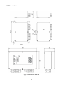
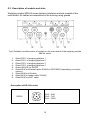
User Manual
Weighing Module MW-04
User manual no.:
ITKU-83-01-03-13-A
BALANCES AND SCALES
RADWAG 26 – 600 Radom, Bracka 28, POLAND
Phone: +48 (0-48) 38 48 800, fax. +48 (0-48) 385 00 10
[email protected]
www.radwag.com
MARCH 2013
2
TABLE OF CONTENTS
1.
2.
3.
4.
INTENDED USE..........................................................................................................................5
PRECAUTIONARY MEASURES................................................................................................5
WARRANTY CONDITIONS........................................................................................................5
TECHNICAL DATA.....................................................................................................................6
4.1. INPUT/OUTPUT parameters ................................................................................................7
5. CONSTRUCTION .......................................................................................................................7
5.1. View ......................................................................................................................................8
5.2. Dimensions ...........................................................................................................................9
5.3. Description of sockets and slots .........................................................................................10
5.4. Diagrams of connecting cables...........................................................................................11
6. 4IN/4OUT MODULE..................................................................................................................13
6.1. IN/OUT diagram..................................................................................................................13
6.2. Description on IN/OUT cables ............................................................................................13
7. INSTALLATION of “MwMANAGER” software.......................................................................14
7.1. Minimum hardware requirements .......................................................................................14
7.2. Installation procedure..........................................................................................................15
8. PC PROGRAM DESCRIPTION ................................................................................................18
8.1. Weighing window ................................................................................................................18
8.2. Application settings .............................................................................................................19
8.2.1. Connection settings...................................................................................................19
8.2.2. Language ..................................................................................................................22
8.2.3. Other .........................................................................................................................23
8.3. Parameters .........................................................................................................................24
8.3.1. User Parameters .......................................................................................................24
8.3.2. Communication settings ............................................................................................25
8.3.3. IN / OUT functions.....................................................................................................28
8.3.4. Previewing available weighing platforms...................................................................30
8.3.5. Previewing accessible A/D converters ......................................................................31
8.4. Functions ............................................................................................................................32
8.4.1. Dosing .......................................................................................................................32
8.4.2. Checkweighing ..........................................................................................................36
8.4.3. Input/output status.....................................................................................................37
9. WEIGHING................................................................................................................................38
9.1. Principles of use..................................................................................................................38
9.2. Zeroing................................................................................................................................39
9.3. Tarring.................................................................................................................................40
9.4. Weighing on dual range scales...........................................................................................40
9.5. Toggling between weighing units........................................................................................41
10. SCALE PARAMETERS ..........................................................................................................42
10.1. Autozero function ..............................................................................................................42
10.2. Median filter.......................................................................................................................43
10.3. Filter ..................................................................................................................................43
11. CHECKWEIGHING .................................................................................................................44
11.1. LO threshold......................................................................................................................44
11.2. MIN/MAX threshold ...........................................................................................................45
12. DOSING ..................................................................................................................................45
3
13. PARAMETERS IN FILE ..........................................................................................................46
13.1. Saving to file......................................................................................................................47
13.2. Uploading file data ............................................................................................................49
14. OFFLINE MODE .....................................................................................................................50
15. ERROR MESSAGES ..............................................................................................................52
16. COMMUNICATION PROTOCOL............................................................................................53
16.1. General information ..........................................................................................................53
16.2. A set of commands recognized by the module .................................................................53
16.3. Response message format ...............................................................................................54
16.4. Description of commands .................................................................................................55
16.4.1. Zero scale ...............................................................................................................55
16.4.2. Tare scale ...............................................................................................................55
16.4.3. Give tare value........................................................................................................55
16.4.4. Set tare ...................................................................................................................56
16.4.5. Send stable result in basic weighing unit of an active weighing platform ...............56
16.4.6. Immediately send the result in basic weighing unit of an active weighing platform 57
16.4.7. Immediately send the result in basic weighing unit of a n weighing platform .........58
16.4.8. Immediately send the result from all weighing platforms in basic weighing units ...58
16.4.9. Send the stable result in current weighing unit .......................................................59
16.4.10. Immediately send the result in current weighing unit ............................................60
16.4.11. Switch on continuous transmission in basic weighing unit ...................................60
16.4.12. Switch off continuous transmission in basic weighing unit ...................................61
16.4.13. Switch on continuous transmission in current weighing unit.................................61
16.4.14. Switch off continuous transmission in current weighing unit.................................61
16.4.15. Set low checkweighing threshold..........................................................................62
16.4.16. Set high checkweighing threshold ........................................................................62
16.4.17. Give value of low checkweighing limit...................................................................62
16.4.18. Give value of high checkweighing limit .................................................................62
16.4.19. Change platform n ................................................................................................63
16.4.20. Send all implemented commands.........................................................................63
17. COMUNICATION MODULE PROFIBUS ................................................................................64
17.1. General information ..........................................................................................................64
17.2. Setting instrument’s address in a Profibus network ..........................................................64
17.3. Memory map .....................................................................................................................65
17.3.1. Output address .......................................................................................................65
17.3.2. Input address ..........................................................................................................66
17.4. Description of variables.....................................................................................................67
17.4.1. Output variables......................................................................................................67
17.4.2. Input variables ........................................................................................................70
4
1. INTENDED USE
Weighing module MW-04 series is intended to design industrial load cell
scales. Depending on application, communication with the weighing module
can be carried out through the following interfaces: RS232, RS485, Ethernet
and Profibus. The MW-04 is designed for cooperation with terminals PUE 5
or PC computers.
Operating of the weighing module MW-04 from a PC level is carried out with
a computer software “MwManager”. A detailed description of the application
is included in the further section of the weighing module user manual.
2. PRECAUTIONARY MEASURES
A. Before putting into use read carefully this user manual. Use the device
as intended;
B. Weighed loads should be placed possibly in the central section of the
weighing platform;
C. The weighing platform should be loaded with objects which gross
weight does not exceed the maximum capacity;
D. Do not leave heavy loads on the weighing platform for longer period
of time;
E. In case of failure, immediately unplug the device from power supply;
F. Devices that are to be decommissioned should be decommissioned
according to valid legal regulations;
3. WARRANTY CONDITIONS
A. RADWAG is obliged to repair or change those elements that appear
to be faulty by production or construction reason,
B. Defining defects of unclear origin and outlining methods of their
elimination can be carried out only in participation of the user and
the manufacturer representatives,
C. RADWAG does not take any responsibility connected with defects
or loss deriving from unauthorized or inappropriate (not adequate
to manuals) production or service processes,
5
D. Warranty does not cover:
• Mechanical failures caused by inappropriate exploitation
of the device or failures of thermal or chemical origin or,
• Defects caused by atmospheric discharge, overvoltage in mains
or other random event,
• Maintenance activities (cleaning of the weighing module).
E. Warranty loss appears if:
• A repair is carried out by an unauthorized service,
• Intrusion into mechanical or electronic construction
of unauthorized personnel,
• Removing or destroying protection stickers for the weighing module.
F. The detailed warranty conditions are listed in the warranty certificate.
4. TECHNICAL DATA
MODEL
MW-04-1
MW-04-2
Number of platforms in standard
2
Max number of platforms
4
Interface
4IN/4OUT module
MW-04-3
RS232,
Ethernet
RS232,
RS485
RS232
PROFIBUS
YES
YES
NO
Housing
Aluminum
IP rating
IP65
Power supply
100 ÷ 240VAC 50 ÷ 60Hz
Power consumption
25W
Working temperature
-10°C ÷ 40°C
Maximum quantity of divisions
from converter
8388608
OIML class
III
Number of verification intervals
6000
Maximum signal increase
19,5mV
Maximum voltage per verification
interval
3,25uV
Minimum voltage per verification
interval
0,4uV
6
Minimum load cell impedance
80
Maximum load cell impedance
1200
Load cell excitation voltage
5V
Load cell connectivity
4 or 6 wires
*) – interface Profibus DP is assembled interchangeably with the module
4IN/4OUT (both modules are not assembled at the same time).
Accessories:
Additional weighing platform module: DP-4
,
4.1. INPUT/OUTPUT parameters
The module features 4 optoisolated inputs, and 4 outputs type OptoMOS.
Output parameters
No. of outputs
4
Outputs type
OptoMOS
Maximum switchable current
0,2A DC
Maximum conducted voltage
50V DC
Inputs parameters
No. of inputs
4
Inputs type
optoisolated
Control voltage range
5 -24V DC
5. CONSTRUCTION
The weighing module MW-04 series comprises a metal housing. The signal
cables are assembled on glands. MW-04 communicates with peripheral
devices through one of the available interfaces: RS485, RS232, Ethernet,
Profibus.
7
The weighing module enables cooperating with a terminal PUE 5 series or a
PC computer. It features 4 optoisolated inputs and 4 outputs type OptoMOS.
The MW-04 is supplied from mains 100-240VAC.
5.1. View
Fig. 1 Weighing module MW-04
8
5.2. Dimensions
Fig. 2 Dimensions MW-04
9
5.3. Description of sockets and slots
Weighing module MW-04 series features interfaces sockets located at the
main board. All cables are assembled in the housing using glands.
Fig.3 Schedule and description of sockets on the main board of the weighing module
MW-04 series
123456789-
Gland PG11 of weighing platform 1
Gland PG11 of weighing platform 2
Gland PG11 of weighing platform 3
Gland PG11 of weighing platform 4
Socket M12 8P for RS232
Gland M16 for Ethernet cable, RS485 or PROFIBUS (depending on module
version)
Gland M16 for 4IN cable
Gland M12 for feeder cable 230VAC
Gland M16 for 4OUT cable
Description of RS 232 socket:
RS232
Pin2 – RxD
Pin3 – TxD
Pin5 – GND
10
5.4. Diagrams of connecting cables
Cable: RS232 – DB9/F
Fig. 4 Cable PT0020
Cable: RS485
Fig. 5 Cable PT0012
Cable: Ethernet
Fig. 6 Cable PT0224
11
Cable: IN/OUT
Fig. 7 Cable PT0209
Cable: PROFIBUS
Fig. 8 Cable no. PT0225
12
6. 4IN/4OUT MODULE
The 4IN/4OUT module is assembled on the main board of the weighing
module MW-04 series. The in and out signal cables are assembled using
glands.
6.1. IN/OUT diagram
Inputs diagram
Outputs diagram
6.2. Description on IN/OUT cables
The signals are available on two cables, one for inputs and the other for
outputs. Below table demonstrates distribution of signals on each wire of the
cable.
CABLE for INPUTS
WIRE no.
1
2
3
4
5
6
7
CABLE for OUTPUTS
SIGNAL
IN1
IN 2
IN3
IN4
COM
+12V
GND
WIRE no.
1
2
3
4
5
6
7
SIGNAL
OUT1
OUT2
OUT3
OUT4
COM
+12V
GND
Signals +12VDC and GND are connected to the feeder of the weighing module
MW-04.
13
7. INSTALLATION of “MwMANAGER” software
Caution:
• In order to install the program on the computer with an older version
of the “MwManager” software, first uninstall the previous software
version.
• The installation manual was made for Windows XP and it is
compatible with former versions of MS Windows.
Proper operation of the software requires installing Microsoft .NET
Framework ver. 2.0 or higher. It is accessible on Microsoft website.
• Proper operation of the program requires installing all accessible
ServicePacks for your operating system, that are supplied by Microsoft.
• Due to continuous software updates there may occur some
discrepancies between the instruction and the program.
• RADWAG company takes no responsibility for the consequences
of the software operation, and any errors resulting from the incorrect
software operation.
• RADWAG company takes no responsibility for loss or protection
of any data caused by the incorrect use of the software or computer.
7.1. Minimum hardware requirements
Correct software operation requires a computer with below specified
configuration:
• A PC computer with installed OS MS Windows 2000/XP/2003/Vista/7,
• processor 2.4 GHz or faster,
• RAM 512 MB or more (recommended 1 GB),
• At least 1 GB of free space on the hard drive,
• Display with minimum resolution 800 x 600 pixels,
• DVD drive.
14
7.2. Installation procedure
1. When having the software installation version, run it with MwManager
x.x.x.x.exe file. Select one of software language version and press OK
button.
2. Press “Next” in the welcoming window.
15
3. Window for specifying installation directory:
Use the window to specify software location on the computer (default:
do not change the path), and press “Next” button.
4. Window for selecting tasks:
Mark / unmark options and press “Next” button.
16
5. Window on readiness to carry out installation process:
To continue press “Install” button.
6. Window on completion of software installation process:
Successfully installed application should be closed by pressing
“Close” button.
17
7. A shortcut will be created on computer’s desktop.
8. PC PROGRAM DESCRIPTION
Operation of the weighing module from PC computer level requires
application ”MwManager”. The application can operate in MS Windows
environment with installed add-on .NET framework 2.0.
The software enables reading mass value, tarring, zeroing, filter setting,
simulating operation of inputs and dosing function for an individual weighing
platform. Setting a function, inputs and outputs is enabled for an individual
weighing platform.
Caution:
1. This manual complies with the software “MwManager” starting from
version 1.0.3.1 and software of the weighing module MW-04 series
from version 1.1
2. The entered values are accepted by pressing Enter button. The
changes are saved in the weighing module on pressing Save button.
All temporary parameters settings that are not saved in the weighing
module are highlighted in red.
3. The look of some windows of software “MWManeger” depends on the
number of operated A/D converters, connected weighing platforms and
their configuration in the weighing module MW-04 series.
8.1. Weighing window
Fig. 9 View of the software’s weighing window
18
On completing initialization procedure, the weighing window displays below
pictograms:
- precise zero indication
- stable measurement result
- weighing unit
- weighing platform number
Function buttons:
-
Zeroing
-
Tarring
-
Weighing platform selection, enabled in case the MW-04
cooperates with more than one weighing platform.
Caution:
Zeroing and tarring functions are enabled for an active weighing platform.
8.2. Application settings
The
tab comprises the settings for connecting with the
weighing module, choosing interface language version and other software
options.
8.2.1. Connection settings
The
tab,
button enables a function
for establishing connection with the weighing module.
19
Fig. 10 Connection settings window
In order to establish a connection with the weighing module MW-04, go to tab
“Select device” and mark
option.
Description:
Select device
Device you want to connect to:
Weighing module MW-01 series
Weighing module MW-04 series
Mark in case of establishing connection with the weighing module
MW-04 series
20
Means of
connection
Interface for connecting to the weighing module
RS 232
Connection via RS232 socket
TCP/IP
Ethernet connection
RS 485
Connection via RS 485 network
Offline
The offline mode is used for saving and editing all indispensable
parameters of the configuration file.
RS232:
Port
Choosing a COM port number to which the weighing module is plugged
Baud rate
Baud rate for the RS232 interface. 57600 bps by default
Parity
Parity bit parameter. “None” by default (non-editable value)
Data bits
Number of data bits. 8 by default (non-editable value)
Stop bits
Number of stop bits. 1 by default (non-editable value)
TCP/IP:
IP address
IP address of the device, default setting 192.168.0.2
Port
Port set in the weight module, default setting 4001
RS485:
Port
Choosing a COM port number to which the weighing module is plugged
Baud rate
Baud rate for the RS232 interface. 57600 bps by default
Parity
Parity bit parameter. “None” by default (non-editable value)
Data bits
Number of data bits. 8 by default (non-editable value)
Stop bits
Number of stop bits. 1 by default (non-editable value)
Address
Weighing module address in network
Caution:
1. The default baud rate of RS232 and RS485 interfaces in the MW-04
is set to 57600 bps by default.
2. If case of problems with establishing a connection to the weighing
module via interfaces RS232, RS485, set and check accessible baud
rates or connect through Ethernet interface.
21
Description of buttons:
Establishing a connection with the weighing module. After
connecting, the button changes its function to “Disconnect” and colour of the
button changes to green.
Terminating communication with the module. In case of
terminating communication with the module, the button changes its function
to “Connect” and its colour changes to red.
8.2.2. Language
Use
tab, and
button to open a window enabling
changing the language of the software.
Fig. 11 Software language version selection window
22
On selecting the language version, press “Apply” button to save the
changes. Present software version provides access to the following
language versions:
• English
• Polish
8.2.3. Other
Use
tab,
button to start other software options.
Fig.12 Other options window
Mark “autostart” option, and after switching on the software automatically
establishes connection to the weighing module, using default or last used
means of connection.
23
Mark “Enable touch screen interface” option to adapt the look of software
“MwManager” to operation on weighing terminal PUE5 series and enabling
operation of the touch screen display.
8.3. Parameters
Tab
comprises all user parameters, communication
parameters of the weighing module and functions of inputs / outputs.
8.3.1. User Parameters
Tab
,
button enables opening a window with user
parameters of the weighing module. The displayed parameters are visible
for an enabled (active) weighing platform and they are editable for each
software user.
Fig.13 User parameters window
24
List of user parameters:
Auto-zeroing
-
YES / NO - enabling / disabling auto-zeroing function
Beep
-
Beep sound (not operated by the weighing module MW-04)
Median filter
-
Setting the value of median filter.
None – means disabling the median filter
Filter
-
Setting the speed of averaging filter operation
None – means disabling the filter
Current unit
-
Toggling between weighing units in the weighing window
Caution:
In case the MW-04 operates a few weighing platforms, then the displayed
parameters enable editing only the weighing platform currently previewed
in the weighing window:
8.3.2. Communication settings
Tab
,
button opens a window with communication
parameters of the weighing module. The parameters are previewed and
accessible for editing for each software user who establishes communication
with the weighing module.
25
• Ethernet
Fig.14 Communication parameters window for Ethernet
Description of window fields:
IP address
-
Device’s IP address, default 192.168.0.2
Subnet mask
-
Ethernet subnet mask, default 255.255.255.0
Default gate
-
Ethernet default gate, default 192.168.0.1
Port
-
TCP communication port, default 4001.
Timeout
-
Inactivity time in which the device breaks communication,
expressed in seconds, range 0 – 300 [s].
26
• RS 232/485
Fig.15 RS communication parameters window
Description of window fields:
Module address
-
Weighing module address in RS 485 network (the network requires
setting different address for each of the devices), default set to 1.
Range from 1 to 254.
Baud rate
RS232
-
Baud rate setting for RS 232 communication interface.
Default 57600 bit/s
Baud rate
RS485
-
Baud rate setting for RS 485 communication interface.
Default 57600 bit/s
On changing the communication parameters, save the settings and restart
the weighing module (by unplugging and repeated plugging to mains) to make
changes effective.
Remember, that the new parameters are inserted in the connection settings
window with the weighing module. See chapter 8.2.1 of this user manual.
27
8.3.3. IN / OUT functions
The weighing module MW-04 series comprises four inputs and four outputs.
Use tab
,
button to open a window enabling
software user to access configuring functions of the weighing module’s inputs
and outputs. Each input and output requires selecting number of a scale /
weighing platform for which its function should be carried out.
Fig. 16 Inputs / Outputs configuring window
28
• Inputs configuration
Functions accessible for inputs:
None
Input disabled
Tarring
Tarring of an individual platform
Zeroing
Zeroing of an individual platform
Start dosing
Initiate dosing process on an individual platform
Stop dosing
Stop dosing process on an individual platform
• Outputs configuration
Functions accessible for outputs:
None
Output disabled
Stable
Signaling stable weighing result over LO mass limit, on an
individual platform
MIN stable
Signaling stable weighing result over LO mass limit but below
MIN limit, on an individual platform
MIN
Signaling unstable weighing result over LO mass limit but below
MIN limit, on an individual platform
OK stable
Signaling stable weighing result between MIN and MAX limits, on
an individual platform
OK
Signaling unstable weighing result between MIN and MAX limits,
on an individual platform
MAX stable
Signaling stable weighing result over MAX limit, on an individual
platform
MAX
Signaling unstable weighing result over MAX limit, on an
individual platform
Caution:
If a function is assigned to a specific output and the same output is used
for bulk or fine dosing then on dosing start and continuation the outputs
will be activated compatibly to the dosing parameters. End of the dosing
process causes switching over the functions to outputs.
29
8.3.4. Previewing available weighing platforms
Tab
,
button opens a simultaneous view of weighing
windows of all weighing platforms operated by the weighing module MW-04.
Additionally, for information purposes, each weighing platform features data
on number A/D converter divisions (or converters), adjustment factor and
start mass.
Caution:
Window look depends on number of used A/D converters, connected
weighing platforms and their configuration.
Fig. 17 An example of a window for previewing four weighing platforms
30
8.3.5. Previewing accessible A/D converters
Tab
,
button enables previewing divisions, adjustment
factor, mass, correction factor and start mass of all available A/D converters.
Caution:
Window look depends on number of used A/D converters, connected
weighing platforms and their configuration.
Fig. 18 Window for previewing divisions from A/D converters
31
8.4. Functions
Tab
to set functions of dosing, checkweighing, inputs and outputs
status and simulation.
8.4.1. Dosing
Tab
,
button opens a window for settings dosing process
parameters of a weighing platform that is active in the weighing window.
Fig. 19 Window on dosing parameters
• Bargraph
The dosing window features a graphic bar visualizing mass indication
within the weighing range of the weighing module.
Ticking the additional option extends bar graph scaling to 120 %
of the maximum dosing limit. If the fine dosing threshold is disabled,
then the bargraph is scaled according to the bulk dosing threshold.
32
Fig. 20 Bargraph scaling for the bulk dosing limit
Fig. 21 Bargraph scaling for the bulk and fine dosing limits
Fig. 22 Bargraph for low mass without scaling
Fig. 23 Bargraph for the same low mass with enabled scaling option
33
•
Dosing parameters
Fig. 24 Window for setting dosing parameters
The dosing process can consist of one or two phases depending on the
needs.
Description of fields:
Threshold fast dosage
Output No
Mass value for which the first dosing
phase is completed.
(switching to the second dosing phase, or
and of dosing process in case of singlephase dosing process.)
Selection of output number or outputs
numbers enabled during the first
dosing phase (and for an active
weighing platform).
Threshold accurate dosing
Output No
Mass value for which the second dosing
phase is completed.
(End of dosing process)
Selection of output number or outputs
numbers enabled during the second
dosing phase (and for an active
weighing platform).
• Dosing status
The dosing status window displays
in the weighing window the current
status of dosing process on an active
weighing platform.
34
Description:
Dosing status
Dosing process status:
DOSAGE – dosing in progress
TERMINATED – dosing terminated by pressing STOP
button.
STOP – dosing stopped,
COMPLETED – Dosing completed.
• Simulation of inputs operation
Inputs simulation enables simulating the operation of a function assigned
to an individual input. See chapter 8.3.3 of this user manual.
Button of function assigned to input 1
Button of function assigned to input 2
Button of function assigned to input 3
Button of function assigned to input 4
• Dosing simulation
The bottom section of the window comprises buttons for starting and
stopping dosing process. They enable starting and stopping the dosing
process independently on the functions assigned to the inputs.
35
8.4.2. Checkweighing
Start option
and press
button to open a window enabling
checkweighing setting for a weighing platform that is active in the weighing
window.
Fig. 25 Checkweighing settings window
Description of fields:
LO threshold
Min threshold
Max threshold
Value of net mass, above which the checkweighing function is
active
Mass value for determining the value of tolerance thresholds.
- below the Min threshold value the MIN limit is signaled
- between the values of Min threshold - Max threshold the
OK limit is signaled.
- above the Max threshold value the MAX limit is signaled.
36
Signaling function with limits:
MIN
OK
MAX
Caution:
The checkweighing signalization in the software is accessible on setting
the functions to outputs.
8.4.3. Input/output status
and press
button to open a window enabling
Start option
setting inputs signalization and setting outputs status.
Fig. 26 Window of inputs and outputs status
37
Software inputs and outputs are numbered according the weighing module
documentation.
input / output enabled
input / output disabled
The simulation of output operation is possible on pressing the output number
which is activated immediately, provided there is no function assigned to the
output.
The simulation of inputs is accessible in the dosing window.
9. WEIGHING
Place weighed load on the weighing platform. As the stable measurement
is displayed, read the measurement result.
pictogram
Caution:
In case the weighing module MW-04 cooperates with more than one weighing
platform, pay attention that the weighing window previews the corresponding
weighing platform for reading mass of weighed loads.
9.1. Principles of use
In order to ensure a long lasting operation and correct measuring of weighed
loads it is advised to:
• Place loads to be weighed on the weighing platform gently and avoiding
shocks:
38
• Place the loads in the centre of the weighing platform (eccentric
weighing errors are outlined in the standard PN-EN 45501 sections
3.5 and 3.6.2):
• Do not load the weighing platform with concentrated force:
• Avoid side loads and particularly side shocks:
9.2. Zeroing
In order to zero the mass indication of an active weighing platform in program
button in the weighing window (located in the
“MwManager” press
the top right corner of the window) or enable the zeroing function.
The display should indicate mass equal to zero and pictograms:
.
and
Zeroing is equivalent to setting a new zero point comprehended by the
scale as a precise zero point. Zeroing is possible only for stable display
status.
39
Zeroing can be carried out by pressing the external push-button connected
to an input configured to zeroing function.
Caution:
Zeroing display status can only be carried out within the ±2% of the maximum
scale capacity. If a zeroed indication is beyond the range ±2% of maximum
scale indication, the display indicates an error message Err2.
The procedure of defining inputs – buttons is described in chapter 8.3.3
of this user manual.
9.3. Tarring
In order to determine net weight of a load weighed on an active weighing
platform , place a container on the weighing platform and on indication
button or enable tarring function. The display
stabilization press
. The scale
should indicate mass equal to zero and pictograms: Net and
is tarred.
While using the tarring function pay attention not to exceed the maximum
measuring range (maximum capacity) of a scale. When taking the load and its
packaging off the weighing platform the display indicates value that is a sum
of tarred weights preceded by minus sign.
Tarring can be carried out by pressing the external push-button connected
to an input configured to tarring function.
Caution:
Tarring cannot be carried out if the scale display indicates zero or negative
values. In such case the display indicates an error message Err3.
The procedure of defining inputs - buttons is described in chapter 8.3.3
of this user manual.
9.4. Weighing on dual range scales
Switching between the 1st range and the 2nd range takes place automatically,
without operator’s interference, (and at the point of reaching the Max of the
1st range).
40
Weighing in range II is signaled by displaying pictogram
in the top left
corner of the display. When unloading the weighing platform, the indication
returns to zero. Weighing in the 2nd range continuous until the indication
returns to zero indication.
Fig. 27 Weighing window in the 2nd range
Return from weighing in the II range to weighing in the I range takes place
automatically on removing the weighed load from the weighing platform and
at the moment the mass indication returns to AUTOZERO zone – confirmed
appearing on the display. Then the pictogram of the II
by pictogram
disappears from the display and the scale automatically
range
returns to weighing with the accuracy of the I range.
9.5. Toggling between weighing units
Change of a weighing unit of an active weighing platform is carried out in a
weighing window of the “MwManager” software by pressing
button in user parameters.
Fig. 28 The main window with changed weighing unit
41
Selection options:
• If the basic weighing unit is [kg], the following units are accessible:
[kg, lb, oz, ct, N, g]. For verified scales, [lb, oz, N] are not accessible;
• If the basic weighing unit is [g], the following units are accessible:
[g, kg, lb, oz, ct, N] For verified scales, [lb, oz, N] are not accessible.
10. SCALE PARAMETERS
Users can adjust the scale to ambient conditions (filtering level) or user
needs (autozero operation).
The parameters are grouped in tab
>
and they are
accessible and editable for an individual weighing platform in the weighing
window.
List of scale parameters:
•
•
•
Autozeroing
Median filter
Filter
10.1. Autozero function
In order to ensure precise scale indications the software “AUTOZERO”
function has been introduced. It is designed to automatically control and
correct scale’s zero indication.
When autozero function is enabled, the subsequent results are compared
in constant time intervals. If two subsequent results differ less than the
declared AUTOZERO range, e.g. 1 interval, the scale automatically sets
and precise zero –
new zero point and pictograms of stability –
are displayed.
If AUTOZERO is enabled, then each measurement always starts from the
precise zero point. There are, however, cases in which the function may
disturb the measuring process. It is for instance while very slow loading
the weighing platform (for instance pouring a load). In such case the zero
correcting system can correct the actual indication of load placed on the
scale’s weighing platform.
42
Procedure:
• Enter the group of User parameters window by pressing
button, choose parameter <Autozeroing> and set its appropriate value.
NO
YES
-
autozero disabled
autozero enabled
10.2. Median filter
The intended use of the median filtering is eliminating short lasting
interference of impulse character (e.g. mechanical shocks).
Procedure:
• Enter the group of User parameters window by pressing
button, select <Median filter> parameter and determine its
value.
Accessible settings:
None
- median filter disabled
0.5, 1, 1.5, 2, 2.5 - median filter enabled
10.3. Filter
The intended use of the averaging filter is adapting the scale to ambient
conditions at a workstation.
Procedure:
• Enter the group of User parameters window by pressing
button, select parameter <Filter> and determine its value.
Accessible settings:
None, Very Fast, Fast, Average (normal), Slow
43
Caution:
The higher filtering level, the longer stabilization time of measurement
result.
11. CHECKWEIGHING
Checkweighing is a function that aims at precise weighing
a sample with pre-defined low and high weighing limits
(checkweighing thresholds (LO – sample mass too low,
HI – sample mass too high, OK – sample mass correct).
Such software solution is a very good means for quick mass value evaluation
with no need for continuous monitoring the measurement result. The above
mentioned weighing status (LO, OK, HI) have their graphic visualization
presented on scale’s display.
The status is also indicated by optical signalization or controlled by the set
of external devices.
>0<
Lo
MIN
Min limit
OK
Max limit
MAX
HI
Fig. 29 Presentation of intervals for checkweighing function
Caution:
The means of enabling the checkweighing mode and its signalization are
described in chapter 8.4.2 of this user manual.
11.1. LO threshold
Parameter <LO threshold> determines the net mass value indicated on the
display which activates operation of outputs for status MIN, OK, MAX.
Procedure:
• Enter parameter <LO threshold>, determine the value of LO limit and
press
button. The
Enter button. Save changes by pressing
changes are saved in weighing module permanent memory.
44
11.2. MIN/MAX threshold
Parameter <MIN threshold> in checkweighing mode determines the net
weight limit for switching between the status from MIN to OK.
Parameter <MAX threshold > in checkweighing mode determines the net
weight limit for switching between the status from OK to MAX.
Output signalization is activated over the set net value of LO threshold.
Procedure:
• Enter parameter < MIN threshold > or < MAX threshold >, determine
the limit value and press Enter key. Save changes by pressing
button. The changes are saved in weighing module
permanent memory.
12. DOSING
Dosing is a function enabling precise load measurement
to a pre-defined target value.
Parameter <Threshold fast dosage> determines in fast (bulk) dosing
the value of net mass below which one or a few outputs are enabled.
(the outputs that are assigned to bulk dosing)
Parameter < Threshold accurate dosing > determines in slow (fine) dosing
the value of net mass below which, but above the value of the bulk dosing
limit, one or a few outputs are enabled. (the outputs that are assigned to fine
dosing).
Procedure:
• Enter parameter < Threshold fast dosage > or < Threshold accurate
dosing >, determine the limit value and press Enter button. Save
button.
changes by pressing
• The changes are confirmed by a message:
45
• If any changes in limits values are introduced and but not saved, then
it is possible to preview the currently set limits by pressing
button.
• The readout is confirmed by a message:
Caution:
Description and parameters of dosing mode is described in chapter 8.4.1 of
this user manual.
13. PARAMETERS IN FILE
“MwManager” software enables saving set parameters in a file format
*.sav. The function can be used for saving weighing module settings
in a backup copy, which is restorable in case of module defect or further
use of the parameters while configuring larger number of weighing modules.
46
Fig. 30 An instance of a window with accessible option for saving and reading a file.
File format:
MW04_(factory number)_YYYY-MM-DD_HH-MM.sav
13.1. Saving to file
Procedure:
•
As the weighing module parameters are set, press
button to save them in a file.
•
Then, using system operation window browse for file saving directory,
and press
button.
47
Fig. 31 System window “Save as”
•
Correctly saved parameters are followed by displaying the below
message:
Caution:
The system window look depends on installed OS version, and may differ
from the one visible in Fig.30.
48
13.2. Uploading file data
Procedure:
•
In order to upload parameters from a file, press
•
Then, using system dialogue window, see fig. 31, select a previously
saved file, and press
button.
button,
Fig. 32 System window „Open”
•
Next, using window for uploading groups of parameters select one
or all parameters to be uploaded to the weighing module.
49
Fig.33 Window for selecting groups of parameters.
The selected parameters are grouped according to their location
in the main software menu.
•
Parameters that are correctly uploaded are confirmed by the below
message:
14. OFFLINE MODE
The Offline mode enables starting different software options with no need to
connect to a weighing module. This means of connection is created to enable
saving parameters without establishing a physical connection to a weighing
device.
50
Fig.34 Window for enabling the Offline mode.
Procedure:
•
On software start, enter connection settings tab and in the connection
settings options select Offline, and press “Connect” button.
•
The weighing window displays a message “Offline”.
•
Set parameters and save them into a file according to description in
chapter 13.1 of this user manual.
51
15. ERROR MESSAGES
Err2
-
Value out of zeroing range
Err3
-
Value out of tarring range
Err8
-
Tarring / Zeroing operation timeout
NULL
-
Zero value from A/D converter
FULL
-
HI
-
LH
-
Maximum measuring range exceeded
Data to be displayed exceeds maximum display
capacity
Start mass error, indication out of range (from -5%
to +15% of start mass)
52
16. COMMUNICATION PROTOCOL
16.1. General information
A. Serial communication protocol “weighing module – terminal”
is designed for establishing communication between a RADWAG
scale and a peripheral device through interfaces: RS232, RS485 and
Ethernet.
B. The protocol consists of commands sent from a peripheral
device to the scale, and responses sent inversely.
C. The responses are sent from the scale on each receipt
of a command. Each response is a reaction for a specific command.
D. Commands which form serial communication protocol enable checking
device’s status, and trigger its reaction, e.g. obtaining measurement
result, etc.
16.2. A set of commands recognized by the module
Command
Description of command
Z
Zero scale
T
Tare scale
OT
Give tare value
UT
Set tare
Send stable result in basic weighing unit of an active weighing
platform
Immediately send the result in basic weighing unit of an active
weighing platform
Immediately send the result in basic weighing unit of a n weighing
platform
Immediately send the result from all weighing platforms in basic
weighing units
S
SI
SP
SIA
SU
Send the stable result in current weighing unit
SUI
Immediately send the result in current weighing unit
C1
Switch on continuous transmission in basic weighing unit
C0
Switch off continuous transmission in basic weighing unit
CU1
Switch on continuous transmission in current weighing unit
CU0
Switch off continuous transmission in current weighing unit
53
DH
Set low checkweighing threshold
UH
Set high checkweighing threshold
ODH
Give value of low checkweighing limit
OUH
Give value of high checkweighing limit
P
Set platform n
PC
Send all implemented commands
Caution:
1. Each command has to be terminated with CR LF characters;
2. When sending subsequent commands without waiting for a response
from a previous one may result in scale losing some of the commands.
The best policy for communication is not sending another
command until the answer for a former command has been received.
16.3. Response message format
After receiving an order, the scale can reply with:
XX_A CR LF
command understood and in progress
XX_D CR LF
command completed (appears only after XX_A)
XX_I CR LF
command understood but not accessible at this moment
XX _ ^ CR LF
command understood but max range is exceeded
XX _ v CR LF
command understood but min range is exceeded
XX _ OK CR LF command carried out (completed)
ES_CR LF
command not recognized
XX _ E CR LF
an error occurred on command carrying out (time limit exceeded
while waiting for stable measurement result (time limit is scale’s
characteristic parameter)
XX
_
- stands for a name of sent command
- substitutes spaces
54
16.4. Description of commands
16.4.1. Zero scale
Format: Z CR LF
Accessible responses:
Z_A CR LF
Z_D CR LF
Z_A CR LF
Z_^ CR LF
Z_A CR LF
Z_E CR LF
Z_I CR LF
- command understood and in progress
- command carried out
- command understood and in progress
- command understood but zeroing range exceeded
- command understood and in progress
- time limit exceeded while waiting for stable measurement result
- command understood but not accessible at this moment
16.4.2. Tare scale
Format: T CR LF
Accessible responses:
T_A CR LF
T_D CR LF
- command understood and in progress
- command carried out
T_A CR LF
T_v CR LF
- command understood and in progress
- command understood but tarring range exceeded
T_A CR LF
T_E CR LF
- command understood and in progress
- time limit exceeded while waiting for stable measurement result
T_I CR LF
- command understood but not accessible at this moment
16.4.3. Give tare value
Format: OT CR LF
Response: OT_TARE CR LF - command carried out
Response format:
55
1
2
3
4-12
13
O
T
space
tare
space
Tare
Unit
14
15
16
unit
17
18
19
space
CR
LF
- 9 characters with right justification
- 3 characters with left justification
Caution:
Tare value is always given in adjustment unit.
16.4.4. Set tare
Format:
UT_TARE CR LF, where TARE - tare value
Accessible responses:
UT_OK CR LF
- command carried out
UT_I CR LF
- command understood but not accessible at this moment
ES CR LF
- command not recognized (tare format incorrect)
Caution:
Use dot in tare format as decimal point.
16.4.5. Send stable result in basic weighing unit of an active weighing
platform
Format: S CR LF
Accessible responses:
S_A CR LF
S_E CR LF
- command understood and in progress
- time limit exceeded while waiting for stable measurement result
S_A CR LF
S_I CR LF
- command understood and in progress
- command understood but not accessible at this moment
S_A CR LF
MASS FRAME
- command understood and in progress
- response is mass value in basic measuring unit for an active
platform
56
Mass frame format which is scale’s response:
1
2-3
4
5
6
7-15
16
S
space
stability
marker
space
character
mass
space
17
18
19
unit
20
21
CR
LF
Example:
S CR LF – command sent from a computer
S _ A CR LF - command understood and in progress
S _ _ _ _ - _ _ _ _ _ _ 8 . 5 _ g _ _ CR LF - command carried out, response
is mass value in basic measuring unit.
16.4.6. Immediately send the result in basic weighing unit of an active
weighing platform
Format: SI CR LF
Accessible responses:
SI_I CR LF
- command understood but not accessible at this moment
MASS FRAME
- response is mass frame in basic weighing unit for an active
platform
Mass frame format which is scale’s response:
1
2
3
4
5
6
7-15
16
S
I
space
stability
marker
space
character
mass
space
17
18
unit
19
20
21
CR
LF
Example:
S I CR LF – command sent from a computer
S I _ ? _ _ _ _ _ _ _ 1 8 . 5 _ k g _ CR LF - command carried out, immediate
response of mass value in basic weighing unit
57
16.4.7. Immediately send the result in basic weighing unit of a n
weighing platform
Format:
SPn CR LF, where n – weighing platform no. (from 1 to 4)
Accessible responses:
SPn_I CR LF
- command understood but not accessible at this moment
MASS FRAME “Pn” CR LF
- immediate response of mass value in basic weighing
unit for n weighing platform
Mass frame format from n weighing platform which is scale’s response:
1
2
3
4
5
6
7-15
16
17
P
n
space
stability
marker
space
character
mass
space
18
19
unit
20
21
CR
LF
Where:
n
Mass
Unit
- weighing platform number
- 9 characters with right justification
- 3 characters with left justification
16.4.8. Immediately send the result from all weighing platforms in basic
weighing units
Format: SIA CR LF
Accessible responses:
SIA_I CR LF - command understood but not accessible at this moment
MASS FRAME “P1” ; MASS FRAME “P2” ; MASS FRAME “P3” ; MASS FRAME
“P4” CR LF - immediate response of mass value from each of all weighing platforms
in basic weighing unit
Mass frame format for each of weighing platforms which is scale’s response:
1
2
3
4
5
6
7-15
16
P
n
space
stability
marker
space
character
mass
space
58
17
18
unit
19
Where:
n
Mass
Unit
- weighing platform number
- 9 characters with right justification
- 3 characters with left justification
Example:
Assume the weighing module is connected with two weighing platforms
(platform 1, platform 2).
S I A CR LF – command sent from a computer
P1_?______118.5_g__;P2_________36.2_kg_;
P 3 _ I ; P 4 _ I CR LF - command understood, immediate responses are
mass values from all weighing platforms in basic weighing unit of each of the
weighing platform. Where: P 3 _ I – platform 3 not accessible, P 4 _ I platform 4 not accessible
16.4.9. Send the stable result in current weighing unit
Format: SU CR LF
Accessible responses:
SU_A CR LF
SU_E CR LF
- command understood and in progress
- time limit exceeded while waiting for stable measurement result
SU_A CR LF
SU_I CR LF
- command understood and in progress
- command understood but not accessible at this moment
SU_A CR LF
MASS FRAME
- command understood and in progress
- response is mass value in current weighing unit
Mass frame format which is scale’s response:
1
S
2
U
3
4
5
6
7-15
16
space
stability
marker
space
character
mass
space
17
18
unit
19
20
21
CR
LF
Example:
S U CR LF – command sent from a computer
S U _ A CR LF - command understood and in progress
S U _ _ _ - _ _ 1 7 2 . 1 3 5 _ N _ _ CR LF - command carried out, response
is mass value in current weighing unit.
59
16.4.10. Immediately send the result in current weighing unit
Format: SUI CR LF
Accessible responses:
SUI_I CR LF
- command understood but not accessible at this moment
MASS FRAME
- response is mass value in current weighing unit
Mass frame format which is scale’s response:
1
2
3
4
5
6
7-15
16
17
S
U
I
stability
marker
space
character
mass
space
18
19
unit
20
21
CR
LF
Example:
S U I CR LF – command sent from a computer
S U I ? _ - _ _ _ 5 8 . 2 3 7 _ k g _ CR LF – command carried out, response is
mass value in current weighing unit
Where: _ - space
16.4.11. Switch on continuous transmission in basic weighing unit
Format: C1 CR LF
Accessible responses:
C1_I CR LF
- command understood but not accessible at this moment
C1_A CR LF
MASS FRAME
- command understood and in progress
- response is mass value in basic weighing unit
Mass frame format which is scale’s response:
1
2
3
4
5
6
7-15
16
S
I
space
stability
marker
space
character
mass
space
60
17
18
unit
19
20
21
CR
LF
16.4.12. Switch off continuous transmission in basic weighing unit
Format: C0 CR LF
Accessible responses:
C0_I CR LF
- command understood but not accessible at this moment
C0_A CR LF
- command understood and in progress
16.4.13. Switch on continuous transmission in current weighing unit
Format: CU1 CR LF
Accessible responses:
CU1_I CR LF
- command understood but not accessible at this moment
CU1_A CR LF
MASS FRAME
- command understood and in progress
- response is mass value in current weighing unit
Mass frame format which is scale’s response:
1
2
3
4
5
6
7-15
16
S
U
I
stability
marker
space
character
mass
space
17
18
19
unit
20
21
CR
LF
16.4.14. Switch off continuous transmission in current weighing unit
Format: CU0 CR LF
Accessible responses:
CU0_I CR LF
- command understood but not accessible at this moment
CU0_A CR LF
- command understood and carried out
61
16.4.15. Set low checkweighing threshold
Format:
DH_XXXXX CR LF, where XXXXX – mass format
Accessible responses:
DH_OK CR LF
- command carried out
ES CR LF
- command not recognized (incorrect mass format)
16.4.16. Set high checkweighing threshold
Format:
UH_XXXXX CR LF, where XXXXX - mass format
Accessible responses:
UH_OK CR LF
- command carried out
ES CR LF
- command not recognized (incorrect mass format)
16.4.17. Give value of low checkweighing limit
Format:
ODH CR LF
Response: DH_MASA CR LF - command carried out
Response format:
1
2
3
4-12
13
D
H
space
mass
space
Mass
Unit
14
15
16
unit
- 9 characters with right justification
- 3 characters with right justification
16.4.18. Give value of high checkweighing limit
Format:
OUH CR LF
Response: UH_MASA CR LF - command carried out
62
17
18
19
space
CR
LF
Mass frame format of scale’s response:
1
2
3
4-12
13
U
H
space
mass
space
Mass
Unit
14
15
16
unit
17
18
19
space
CR
LF
- 9 characters with right justification
- 3 characters with right justification
16.4.19. Change platform n
Format:
Pn CR LF, where n – weighing platform no. (from 1 to 4)
Accessible responses:
Pn_OK CR LF
- command carried out
Pn_I CR LF
- command understood but not accessible at this moment
ES CR LF
- command not recognized (incorrect platform number)
16.4.20. Send all implemented commands
Format:
PC CR LF
Response:
PC_A_”Z,T,S,SI,SP,SIA,SU,SUI,C1,C0,CU1,CU0,DH,ODH,UH,OUH,
OT,UT,PC" - command carried out, terminal sent all implemented
commands.
63
17. COMUNICATION MODULE PROFIBUS
17.1. General information
Communication module Profibus ensures exchanging data between a
superordinated controlling unit (master) and a weighing module
MW-04 (slave) in accordance with protocol Profibus DP.
The superordinated unit (master):
•
•
cyclically reads signals from the weighing module MW-04,
cyclically saves status to the weighing module MW-04.
Functions of Profibus communication with the weighing module MW-04:
•
•
•
•
•
•
•
•
•
•
•
•
•
Mass readout from the weighing module
Tarring the weighing module
Zeroing the weighing module
Reading module’s status
Reading current weighing unit
Setting and reading tare value
Setting and reading LO threshold value
START / STOP of dosing process
Setting and reading the value of bulk (fast) dosing threshold
Setting and reading the value of fine (slow) dosing threshold
Reading the status of dosing process
Setting and reading Min threshold value
Setting and reading Max threshold value
17.2. Setting instrument’s address in a Profibus network
The address of the weighing module MW-04 in Profibus network has to be set
in accordance with module addressing specification. (See point 8.3.2 of this
user manual – „Communication settings”). Field module address is used to
set corresponding address of the device in Profibus network.
64
17.3. Memory map
17.3.1. Output address
Address
0
1
2
3
4
5
6
7
8
9
M1
M1
M1
M1
T1
T1
T1
T1
J1
J1
1
S1
S1
LO1
LO1
LO1
LO1
M2
M2
M2
M2
2
T2
T2
T2
T2
J2
J2
S2
S2
LO2
LO2
3
LO2
LO2
M3
M3
M3
M3
T3
T3
T3
T3
4
J3
J3
S3
S3
LO3
LO3
LO3
LO3
M4
M4
5
M4
M4
T4
T4
T4
T4
J4
J4
S4
S4
6
LO4
LO4
LO4
LO4
-
-
-
-
MIN
MIN
7
MIN
MIN
MAX
MAX
MAX
MAX
DS
DS
DS
DS
8
DW
DW
DW
DW
-
-
-
-
-
-
9
-
-
-
-
-
-
-
-
-
-
10
SK
SK
ST1
ST1
ST2
ST2
ST3
ST3
ST4
ST4
Offset
0
Tab. 1
M1
M2
M3
M4
T1
T2
T3
T4
J1
J2
J3
J4
S1
S2
S3
S4
- Mass for weighing platform no. 1, 4 bytes, float
- Mass for weighing platform no. 2, 4 bytes, float
- Mass for weighing platform no. 3, 4 bytes, float
- Mass for weighing platform no. 4, 4 bytes, float
- Tare for weighing platform no. 1, 4 bytes, float
- Tare for weighing platform no. 2, 4 bytes, float
- Tare for weighing platform no. 3, 4 bytes, float
- Tare for weighing platform no. 4, 4 bytes, float
- Current weighing unit for weighing platform no. 1, 2 bytes, word
- Current weighing unit for weighing platform no. 2, 2 bytes, word
- Current weighing unit for weighing platform no. 3, 2 bytes, word
- Current weighing unit for weighing platform no. 4, 2 bytes, word
- Status of weighing platform no. 1, 2 bytes, word
- Status of weighing platform no. 2, 2 bytes, word
- Status of weighing platform no. 3, 2 bytes, word
- Status of weighing platform no. 4, 2 bytes, word
65
LO1
LO2
LO3
LO4
MIN
MAX
DS
DW
SK
ST1
ST2
ST3
ST4
- LO threshold of weighing platform no. 1, 4 bytes, float
- LO threshold of weighing platform no. 2, 4 bytes, float
- LO threshold of weighing platform no. 3, 4 bytes, float
- LO threshold of weighing platform no. 4, 4 bytes, float
- MIN threshold of an active platform, 4 bytes, float
- MAX threshold of an active platform, 4 bytes, float
- Bulk (fast) dosing threshold of an active platform, 4 bytes, float
- Fine (slow) dosing threshold of an active platform, 4 bytes, float
- Adjustment status of an active platform, 2 bytes, word
- Process status for weighing platform no. 1, 2 bytes, word
- Process status for weighing platform no. 2, 2 bytes, word
- Process status for weighing platform no. 3, 2 bytes, word
- Process status for weighing platform no. 4, 2 bytes, word
17.3.2. Input address
Address
Offset
0
0
1
2
3
4
5
6
7
8
9
C
C
CP
CP
P
P
T
T
T
T
1
LO
LO
LO
LO
-
-
MIN
MIN
MIN
MIN
2
MAX
MAX
MAX
MAX
DS
DS
DS
DS
DW
DW
3
DW
DW
-
-
-
-
-
-
-
-
4
-
-
-
-
-
-
-
-
MW
MW
5
MW
MW
-
-
-
-
-
-
-
-
Table. 2
C
CP
P
T
LO
MIN
MAX
DS
DW
MW
- Command, 2 bytes, word
- Command with a parameter, 2 bytes, word
- Selected (active) weighing platform
- Tare for a platform, 4 bytes, float
- Lo threshold of a platform, 4 bytes, float
- MIN threshold of a platform, 4 bytes, float
- MAX threshold of a platform, 4 bytes, float
- Bulk (fast) dosing threshold of a platform, 4 bytes, float
- Fine (slow) dosing threshold of a platform, 4 bytes, float
- Mass of a standard for a platform, 4 bytes, float
66
17.4. Description of variables
17.4.1. Output variables
Readout of output variables enables obtaining data on instrument’s status.
Caution:
All output values, except for mass, are displayed in adjustment/calibration
unit
Name of output variable
address
mass of platform no. 1
tare of platform no. 1
unit of platform no. 1
status of platform no. 1
LO of platform no. 1
mass of platform no. 2
tare of platform no. 2
unit of platform no. 2
status of platform no. 2
LO of platform no. 2
mass of platform no. 3
tare of platform no. 3
unit of platform no. 3
status of platform no. 3
LO of platform no. 3
mass of platform no. 4
tare of platform no. 4
unit of platform no. 4
status of platform no. 4
LO of platform no. 4
MIN of an active platform
MAX of an active platform
bulk (fast) dosing threshold of an
active platform
fine (slow) dosing threshold of an
active platform
0
4
8
10
12
16
20
24
26
28
32
36
40
42
44
48
52
56
58
60
68
72
67
length
[word]
2
2
1
1
2
2
2
1
1
2
2
2
1
1
2
2
2
1
1
2
2
2
data type
float
float
word
word
float
float
float
word
word
float
float
float
word
word
float
float
float
word
word
float
float
float
76
2
float
80
2
float
adjustment status of an active
platform
process status of platform no. 1
process status of platform no. 2
process status of platform no. 3
process status of platform no. 4
100
1
word
102
104
106
108
1
1
1
1
word
word
word
word
Table. 3
• mass – mass value in current unit is returned
• tare – tare value in calibration/adjustment unit is returned
• unit – determines current (displayed) weighing unit
Byte no.
Unit
g
kg
ct
lb
oz
N
gram
kilogram
carat
pound
ounce
Newton
B5
B4
B3
B2
B1
B0
Dec
0
0
0
0
0
1
0
0
0
0
1
0
0
0
0
1
0
0
0
0
1
0
0
0
0
1
0
0
0
0
1
0
0
0
0
0
1
2
4
8
16
32
• status – status – determines scale (platform) status
Status
byte
Task
Dec
6
correct measurement (no error message
from scale)
stable measurement
scale in zero indication
scale tarred
scale in second weighing range
scale in third weighing range
scale reports NULL error
7
scale reports LH error
128
8
scale reports FULL error
256
0
1
2
3
4
5
68
1
2
4
8
16
32
64
Example:
byte no.
B8
B7
B6
B5
B4
B3
B2
B1
B0
0
0
0
0
1
0
0
1
1
value
The scale does not report an error, the measurement is stable in
the second weighing range.
• LO - the value of LO threshold in calibration/adjustment unit is returned
• MIN - set value of MIN Threshold (in calibration/adjustment unit) is
returned.
• MAX - set value of MAX Threshold (in calibration/adjustment unit) is
returned.
• Bulk (fast) dosing threshold – set value of bulk (fast) dosing threshold
(in calibration/adjustment unit) is returned.
• Fine (slow) dosing threshold – set value if fine (slow) dosing threshold
(in calibration/adjustment unit) is returned
• Adjustment status – determines the status of adjustment process
Adjustment status
Process not accessible
Process completed successfully
Process in progress
Error – out of range
Error – timeout
Determining process aborted
Waiting for data
Decimal value
-1
0
1
2
3
4
5
• Process status – determines the status of dosing process:
Decimal value of
a variable (Dec)
0
1
2
3
Process status
process disabled
(inactive)
dosing start
dosing stop
end of dosing process
69
Byte no.
B1
B0
0
0
0
1
1
1
0
1
17.4.2. Input variables
Saving the input variables in the weighing module MW-04 enables controlling
module’s operation.
Caution:
All input values are set in relation to calibration/adjustment unit.
Name of input variable
address length [word]
data type
command
0
1
word
complex command
2
1
word
platform
4
1
word
tare
6
2
float
LO
10
2
float
MIN
16
2
float
MAX
20
2
float
bulk (fast) dosing threshold
24
2
float
fine (slow) dosing threshold
28
2
float
mass of a standard
48
2
float
Complex command parameters
Table. 4
• command – basic command. Setting of an appropriate command’s byte
is directly responsible for carrying out a task, in accordance with below
table:
command
bytes
task
Dec
0
Platform zeroing
1
1
Platform tarring
2
5
dosing process start
32
6
dosing process stop
64
8
Determine start mass
256
9
Determine adjustment factor
512
10
Save factors
1024
70
Example:
0000 0000 0010 0000 – command carried out, dosing process start
on an active weighing platform.
• complex command - Setting of an appropriate command’s byte is
directly responsible for carrying out a task, in accordance with below
table:
command
task
bytes
0
1
3
4
5
6
7
8
Dec
setting tare value of an active platform
setting LO threshold value of an active platform
setting MIN threshold value of an active platform
setting MAX threshold value of an active platform
setting the value of bulk (fast) dosing threshold of
an active platform
setting the value of fine (slow) dosing threshold of
an active platform
Setting mass of a standard for an active platform
Setting an active weighing platform
1
2
8
16
32
64
128
256
Example:
0000 0000 0000 0010 – command carried out, LO threshold set to value
given in LO parameter (address 10); See Table. 4.
Caution:
A complex command requires setting an appropriate parameter of
address from 4 to 48. See Table. 4.
• platform – complex command parameter – number of an active weighing
platform:
Parameter decimal
value
0
1
2
3
Weighing platform
no.
1 platform
2 platform
3 platform
4 platform
71
• tare – complex command parameter – tare value
(in calibration/adjustment unit)
• LO – complex command parameter – LO threshold value
(in calibration/adjustment unit)
• MIN - complex command parameter – MIN threshold value
(in calibration/adjustment unit).
• MAX - complex command parameter – MAX threshold value
(in calibration/adjustment unit).
• bulk (fast) dosing threshold – complex command parameter –
value of bulk (fast) dosing threshold (in calibration/adjustment unit).
• fine (slow) dosing threshold – complex command parameter –
value of fine (slow) dosing threshold (in calibration/adjustment unit).
• mass of a standard – complex command parameter –
mass of a standard (in calibration/adjustment unit).
Caution:
A command or a command with a parameter is executed once on detecting
its corresponding byte setting. Should a command with the same byte be
re-executed, first the byte must be reset.
Example:
command
address 1
address 0
tarring
zeroing command bytes
tarring
0000 0000
0000 0000
0000 0000
0000 0010
0000 0000
0000 0010
72
MANUFACTURER
OF ELECTRONIC WEIGHING INSTRUMENTS
RADWAG WAGI ELEKTRONICZNE
POLAND, 26 – 600 Radom, Bracka 28
Phone. +48 (48) 38 48 800, fax. + 48 (48) 385 00 10
[email protected]
www.radwag.com
73