1
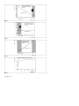
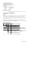
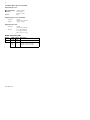
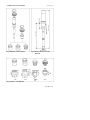
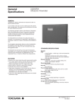
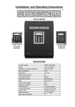
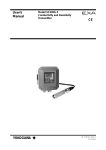
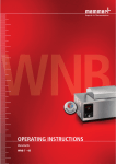
User’s
Manual
Model PH18
Differential pH sensor
IM 12B6J4-E-A
1st edition
(Rev. 4th edition H)
TABLE OF CONTENTS
PREFACE...........................................................................................................................1
1.INTRODUCTION ............................................................................................................3
2.GENERAL SPECIFICATIONS ........................................................................................5
2-1. Model PH18 differential pH sensor............................................................................5
2-2. Model WU18 cable for PH18 sensor ........................................................................6
2-3. Dimensions of the PH18SA ......................................................................................7
3.THE TYPE 18 PH PROBE..............................................................................................8
3-1.Typical applications ..................................................................................................8
3-2.Handling information for the glass lined pH probe ....................................................8
3-3.Storage and hydration ..............................................................................................8
3-4.Installation ................................................................................................................8
3-5.PH18 Installation examples ......................................................................................9
4.EXA PH202 OR PH402 INSTRUMENT ......................................................................10
4-1.Set-up ....................................................................................................................10
5.CALIBRATION ..............................................................................................................11
5-1.Calibration set-up....................................................................................................11
5-2.Isopotential pH value ..............................................................................................11
5-3.SLOPE ..................................................................................................................11
5-4.ASY ........................................................................................................................11
5-5.Process Temperature compensation ......................................................................11
6.CLEANING/STERILIZATION ......................................................................................12
6-1.Acceptable CIP cleaning processes........................................................................12
6-2.Sterilization methods ..............................................................................................12
7.MAINTENANCE............................................................................................................12
8. POSITION OF THE O-RINGS ......................................................................................13
9.ACCESSORIES ............................................................................................................13
APPLICATION DATA SHEET PH DIFFERENTIAL PH SENSOR ..................................14
IM 12B6J4-E-A
Caution - Inappropriate handling can
cause damage.
Striking or scratching the sensor against
hard surfaces such as steel, stone, glass or
ceramic, may cause damage to the
enamel. Such damage may not affect the
sensor performance immediately, but after
prolonged exposure to the process, flaking
of the enamel may occur.
Note - Enable impedance checks in the
PH202 or PH402
The sensor impedance checking can give
early warning of damage to the enamel
layers. If the transmitter signals an
impedance failure of the PH18, the sensor
should be removed from the process, as
soon as possible (within 24 hours). The
loss of significant amounts of enamel may
thus be avoided.
IM 12B6J4-E-A
1
PREFACE
The PH18 should only be used with
equipment that meets the relevant IEC,
American or Canadian standards.
Yokogawa accepts no responsibility for the
misuse of this unit.
The PH18 is packed carefully with shock
absorbing materials, nevertheless, it may
be damaged or broken if subjected to
strong shock, such as if the package is
dropped. Handle with care. Although the
PH18 has a weatherproof construction, the
connections can be harmed if it becomes
submerged in water or becomes
excessively wet.
Do not use an abrasive in cleaning the
PH18.
Notice
Contents of this manual are subject to
change without notice. Yokogawa is not
responsible for damage to the sensor, poor
performance, or losses resulting from such,
if the problems are caused by:
1. Incorrect operation by this user.
2. Use of the sensor in the wrong
applications.
3. Use of the sensor in an adverse
environment or incorrect utility program
4. Repair or modification of the sensor by
an engineer not authorized by
Yokogawa.
Warranty and service
Yokogawa products and parts are
guaranteed free from defects in
workmanship and material under normal
use and service for a period of (typically) 12
months from the date of shipment from the
manufacturer. Individual sales organisations
can deviate from the typical warranty
period, and the conditions of sale relating
to the original purchase order should be
consulted. Damage caused by wear and
tear, inadequate maintenance, corrosion,
or by the effects of chemical processes are
excluded from this warranty coverage.
In the event of warranty claim, the defective
goods should be sent ( freight paid) to the
service department of the relative sales
organisation for repair or replacement (at
Yokogawa discretion).
The following information must be included
in the letter accompanying the returned
goods:
1. Part number, model code and serial
number.
2. Original purchase order and date.
3. Length of time in service and a
description of the process.
4. Description of the fault, and the
circumstances of failure.
5. Process/environmental conditions that
may be related to the installation failure
of the device.
6. A statement whether warranty or nonwarranty service is requested.
7. Complete shipping and billing
instructions for return of material , plus
the name and phone number of a
contact person who can be reached
for further information.
Returned goods that have been in contact
with process fluids must be decontaminated/disinfected before shipment. Goods
should carry a certificate to this effect, for
the health and safety of our employees.
Material safety data sheets should be
included for all components of the
processes to which the equipment has
been exposed.
Unpacking and checking
Upon receipt of the goods, carefully
inspect the shipping package for any
evidence of damage. If the carton is
damaged, notify the shipping agent and
the sales organisation immediately.
If the shipping package is not damaged,
remove the products and parts. Confirm
that all items shown on the packing list are
available and that the package does not
contain any parts or accessories fillers.
Notify the sales organisation if items are
missing.
PH18 sensor
The box of the PH18 sensor contains the
following items:
Sensor complete, possible options (check
part number for possible options),
instruction manual, material certificate and
quality inspection certificate. The WU18
cable is packed separately.
IM 12B6J4-E-A
3
1. INTRODUCTION
The PH18 is not a conventional electrode. It
relies on two dissimilar ion sensitive enamel
membranes to generate the signal. The
measuring element is like a pH electrode,
and the reference like a Sodium ion
electrode.
Therefore the PH18 can only be used in
combination with pH meters that feature:
1 Dual high impedance inputs
2 Adjustable setting for Isothermal
Point
3 Adjustable temperature coefficient
The Yokogawa models PH202 and
PH402 satisfy these requirements.
In both cases the membrane enamels are
bonded directly to the metal substrate with
no filling solution.
The response curves Fig. 1 (pH), Fig. 2
(reference) and Fig. 3 (application range)
show the way in which the potential is
generated at each element and combined
in the output of the sensor.
Fig. 1 Above pH11 the effect of sodium on
the pH membrane starts to cause
non-linearity (Sodium error)
Fig. 2 Below pH3 the high Hydrogen ion
content causes a change in the
reference response
Fig. 3 A linear response to pH is obtained
between 3 and 11 pH
Fig. 4 A plot of reference voltage against
Sodium content.
Because of the exponential nature of the
response, it is plain that above about 0.5 N
Na+ (30 g NaCl/l) in the solution, the
reference output remains virtually constant.
Of course when the Sodium concentration
remains constant in a process the reference
voltage will also be constant at much lower
levels of Sodium.
It is because of the need to evaluate the
chemistry of the process, that it is
necessary to have an Application Data
Sheet (page 16) completed before
approval for this sensor can be made.
The mechanical construction of the sensor
also means that it may be used in
processes involving both high temperatures
and pressures. By eliminating the filling
solutions, the sensor is truly robust and can
even withstand severe thermal shocks that
would ruin most systems.
The stainless steel mounting adapter forms
the liquid earth (solution ground) connection
needed to ensure best stability of
measurement. EXA also uses this
connection in the diagnostic circuit.
The PH18 is a differential pH sensor. It
does not measure absolute pH except in
limited applications. It does, however,
measure a single control point
accurately, repeatably and with minimum
maintenance
The revolutionary measuring principle has
some big advantages. The absence of filling
solutions and reference junctions virtually
eliminates the problems caused by aging
and pollution of the reference sensor.
Regular cleaning of the sensor virtually
eliminates drift, and the sensor benefits
from a very long working life. It is vital,
however, to fit the sensor to the application
correctly. The special nature of the
reference element dictates that there must
be a certain Sodium level in the process.
Fig. 4 shows a plot of reference voltage
against Sodium content.
IM 12B6J4-E-A
4
Measuring Enamel mV vs.
pH in solution containing
0.1N Na+
Operating range
pH of sample
Fig. 1
Reference Enamel mV vs
pH in solution containing
0.1N Na+
Operating range
pH of sample
Fig. 2
PH18 system output
pH reading vs. pH in
solution containing
0.1N Na+
Operating range
pH of sample
Fig. 3
Reference Enamel mV vs Na + content
Fig. 4
IM 12B6J4-E-A
5
2. GENERAL SPECIFICATIONS
2-1. Model PH18 differential pH sensor
Temperature sensor
: Pt1000 Ω RTD
Wetted parts
- pH sensor
: pH sensitive enamel
- Reference sensor : Na+ sensitive enamel
- Liquid earth
: via SS adapter
- O-rings
: EPDM
- Adapters
: SS 316
Max. measuring range
: 3 to 11 pH
(The actual range will be advised with reference to the completed
application data sheet)
Temperature range : 0 to 140 ºC (284 ºF)
Pressure range
: -1 to 15 Bar (214 psi)
NOTE:
The use of this sensor is highly application specific.Your local Yokogawa sales office will be
pleased to advise on the suitability of your application, on receipt of the completed
application data sheet. Any and all information received by Yokogawa will be treated in the
strictest confidence. To maintain traceability, the completed application data sheet will form
part of the contract of sale.
Yokogawa offers no function guarantee for applications where the attached data sheet
(page 16) has not been satisfactorily completed. This does not affect the normal Yokogawa
warrantly covering defects in materials or workmanship.
MODEL AND SUFFIX CODE
Model
PH18
Sensor
mounting
O-ring
material
Instruction
manual
Options SA
Suffix Option Description
code code
......................... Model PH18 Differential pH sensor
-SA................... Compatible with 25mm
......................... process connection
-E................. Ethylene-propylene (EPDM)
-E................
-N...............
/SWA....
/SWR...
/SNS....
/SBS....
/BSA1..
English language
No manual
Angled weld-in adapter (SS316)
Straight weld-in adapter (SS316)
Adapter 1” NPT (SS316)
Adapter ISO 7/1-R1, JIS 1”(SS316)
Blind plug SS316 (EPDM O-ring)
Note:
The sensor is supplied with
cable connector. For first
installation cable must be
specified as well. (see par.2-2)
Note:
The material certificate 3.1.B is
supplied with the sensor and
the options.
IM 12B6J4-E-A
6
2-2. Model WU18 cable for model PH18
differential pH sensor
Max. temperature : 110 ºC (230 ºF)
Material
: Thermoplastic
Rubber (T.P.R.)
Colour
: Blue.
Shipping details sensor and adapter
- Package
: wxhxd
350 x 220 x 110 mm
- Weight
: approx. 1.4 kg
Shipping details cable
- Package
: wxhxd
350 x 220 x 110 mm
- Weight
: 2 m. approx. 0.6 kg
: 5 m. approx. 0.9 kg
: 10 m. approx. 1.4 kg
MODEL AND SUFFIX CODE
Model
WU18
Suffix Option Description
code code
......................... Cable for Differential pH Sensor
-02 ................... 02 meter connection cable
-05 ................... 05 meter connection cable
-10 ................... 10 meter connection cable
IM 12B6J4-E-A
7
2-3. Dimensions of the PH18-SA
Fig. 5 PH18-SA and the adapters
/SWR
/SWA
in mm (inches)
Fig. 6 External dimensions of the
PH18-SA
/SBS
/SNS
/BSA1
Fig. 7. Options of the PH18-SA
IM 12B6J4-E-A
8
3. THE TYPE 18 PH PROBE
3-1. Typical applications
• Fermentation
• Continuous reactions
• Production of diary products
• Product monitoring
3-2. Handling information for the glass
lined pH probe.
The differential pH probes are pressure and
thermal shock resistant due to the fused
steel/enamel construction. The probes have
a very high mechanical stability and are
extremely strong.
Inappropriate handling, e.g. hitting and
scratching the probe on steel, ceramics,
glass or stone may cause damage to the
probe. Depending on the scope of the
damage, the probe may not fail immediately
but rather when the temperature changes. If
a defective measuring probe remains in
aqueous solutions for prolonged periods of
time enamel may flake.
Enable the EXA impedance monitoring. If
sensor damage is indicated, the measuring
probe must be immediately removed (within
24h) after an alarm message. All probes for
use in the food sector are tested with a
voltage of 12 kV and conditioned for 5
hours in steam at a temperature of 134 °C.
3-3. Storage and hydration
The PH18 Probe can be stored dry for an
indefinite period of time at temperatures
between -30 and +80 ºC. After prolonged
storage or if this is a new probe from the
factory a simple steam sterilization should
be performed for 15-30 minutes prior to
calibration. This procedure revitalizes the
probes giving it a stable reference potential.
If steaming is not possible soak the PH 18
for 45-60 minutes in hot water (65 to
85 ºC). If steaming or a hot soak can not be
done, place the Probe in a standard pH7
Buffer solution for 24 hours prior to
installation. The probe must be immersed
so that both measuring elements are
covered with buffer.
IM 12B6J4-E-A
3-4. Installation
Procedure:
1. Remove the probe from the packaging,
remove the protective plastic hose and
carefully introduce the probe into the
nozzle.
2. Fasten probe with union nut
3. Connect cable. For this purpose, loosen
the heavy gauge conduit connection at
the protective plastic cover, push out
the connector, put the connector in the
proper position, and firmly press it into
the female connector of the probe
(water- tight interlock). Push the
protective cover and O ring sealing onto
the probe until the stop and tighten the
heavy gauge conduit connection again
manually.
4. The cable with high temperature
stability (blue) must be fastened
vibration free. The cable must not be
laid together with power cables.
Only suitable transmitters with symmetrical
high impedance inputs may be used. The
following units are approved:
• Yokogawa EXA PH 202
• Yokogawa EXA PH 402
9
3-5. PH18 Installation examples
Socket for connection
cable
Primary adapter
pH enamel
Reference enamel
Fig. 11 The primary adapter is used to
make a connection to the process used by
the transmitter as the liquid earth (solution
ground). This is needed for optimum
stability of the measurement and is used in
the impedance checking circuit.
Example A. Straight weld-in adapter
through a vessel wall.
Example B. 1” Screw-in adapter with
existing pipe nipple through a
vessel wall.
Example C. Angled weld-in adapter in
large bore pipe.
Example D. Angled weld-in adapter
mounted in a bend
Example E. Screw or weld-in adapter
mounted in a large bore pipe.
Example F. Screw or weld-in adapter
mounted on top of a large
bore pipe
Fig. 12. Model 18 elements
Note 1:
When measuring in plastic tanks
or pipes, ensure that the adapter is
wetted by the process. Avoid
installations where an air pocket can be
created (see fig 12 F). This isolates the
adapter, and hence loses the liquid earth
connection.
Note 2:
Flow rate from the side of the sensor (Fig
11) should not exceed 2 meters/second
in low viscosity fluids. In high viscosity
fluids (> 5cP) use only installation as
shown in Fig. 12 (D).
IM 12B6J4-E-A
10
4. EXA PH202 OR PH402 INSTRUMENT
4-1. Set-up
The EXA PH202 and PH402 are both
designed with dual matched high
impedance inputs which are necessary
when using a pH probe like the Model PH
18 with both a measuring and a reference
electrode that are high impedance. To
prepare the EXA instrument to work with
the PH18 make sure the input impedance
jumpers are placed in the correct positions:
PH202: See table 3-1 and fig. 3-8 on page
3-7 in the PH202 Instruction
Manual (IM 12B6C3-E-H) for
jumper positions.
PH402: See figure 3-9a on page 3-8 in the
PH402 Instruction Manual
(IM 12B6B3-E-H) for jumper
positions.
Since the Model PH18 has high impedances for both the measuring and the
reference elements, the high impedance
check functions (Service Codes 03 & 04)
must be set up according to the
procedures outlined in Section 5.3.1 in
either the PH202 or the PH402 Manual.
The Calibration check also needs to be
changed. Here you are instructed to set:
Service Code 03:
Change settings from 1.1.1 to 1.0.1 by
using the ^ and > keys.
Low limit 1Megohm. High limit 1 Gigaohm.
Service Code 04:
Change settings from 0.0.1 to 1.0.1 by
using the ^ and > keys.
Low limit 1Megohm. High limit 1 Gigaohm.
Service Code 05:
Change settings from 1.1 to 0.1 by using
the ^ and > keys. This disables the As. Pot.
check which is not appropriate for the
PH18 system.
Once the jumpers and impedance Service
Codes (03 & 04), Calibration Check (05) and
Temperature element have been set
correctly, wire the probe cable to the
instrument as shown in Fig. 13. Power
wiring instructions are located in the
respective instrument manuals:
PH202: See section 3-4-3 on page 3-6 in
the PH202 Instruction Manual
(IM 12B6C3-E-H).
PH402: See section 3-3-3 on page 3-5 in
the PH402 Instruction Manual
(IM 12B6B3-E-H).
Measuring range
MEASURE
SCREEN
SCREEN
REFERENCE
LIQUIDEARTH
TEMPERATURE
TEMPERATURE
1
2
Model PH18
sensor
pH of sample
Fig. 13 Connection diagram WU18 for
PH402 and PH202
IM 12B6J4-E-A
Fig. 14. Corrosion curve of the Model
PH18 Enamel
11
5. CALIBRATION
proper functioning of the sensor.
5-1. Calibration set-up
All pH sensors are characterized by
Isopotential (ITP), Asymmetry Potential
(ASY) and SLOPE (SL). Typically the ITP is
set by the factory for specific sensor types
and the ASY and the SL are adjusted by
the user during his buffer calibrations.
Calibration of the PH18 is slightly different
from calibration of conventional pH sensors
due to the differential nature of the
measurement. The ITP and SL are set
during commissioning and ASY is adjusted
by the user during his Grab Sample
calibrations.
5-4. ASYMMETRY Potential
The default setting for Asymmetry potential
is 0 mV at Isopotential pH value. This value
is always wrong for the PH18 sensor and
therefore the Asymmetry Potential must be
calibrated always. This cannot be done with
conventional pH buffer solutions, since
these buffer solutions will have salt
compositions, which differ from the actual
process. Therefore the calibration is done
using the grab sampling method: During the
most important stage of the pH control
application a sample is drawn and the pH of
the sample is measured with a calibrated
conventional pH meter. The analyzer is
adjusted to this value using the MAN.CAL
mode.
Notes: This adjustment should be done at
the normal working temperature at the most
important stage of the process (the control
setpoint, or the critical part of the pH
profile). This avoids the need for process
temperature compensation for constant
temperature processes.
5-2. Isopotential pH value
The default setting for the Isopotential point
is 0 mV at 7.00 pH, because most
manufacturers of Glass electrodes use 7
pH as internal fill solution. The PH18
differential sensor has two measuring
elements: one pH element which has an
Isopotential pH value of 1 pH and one pNa
element, which has an Isopotential pNa
value of –2. The Isopotential pH value of the
differential sensor depends on the Salt
concentration. It is recommended to set
the ITP as a function of the Conductivity
according to the graph.
5-3. SLOPE
The default setting for SLOPE is 100% of
theoretical value, which is 59,16
mV/pH@25°C. It is only possible to calibrate
the SLOPE, if pH buffers are used with
identical salt concentration. These buffers
are not commercially available, so it is
recommended not to perform a SLOPE
calibration, but leave the analyzer in its
default settings. It is however recommended
to perform a regular SLOPE check to verify
5-5. Process Temperature
Compensation
This setting is needed only when the
temperature of the process is not
(reasonably) constant. When setting
process TC, it should be done before step
5-4. to avoid influencing the Asymmetry
potential calibration.
The procedure is as follows: Allow sensor to stabilize fully in the process.
Note down the temperature and pH
readings (t1 & pH1).
Allow sample and sensor to cool (together)
to room temperature, and stabilize.
Again note down the temperature and pH
readings (t2 & pH2)
T.C. = (pH1-pH2)x10/(t1-t2) pH/10°C
Note: to calculate TC from temperature
readings in Farenheit,
TC = (pH1-pH2)x18/(t1-t2)
IM 12B6J4-E-A
12
6. CLEANING/STERILIZATION
7. MAINTENANCE
The probe can be cleaned/sterilized inside
the reactor. For CIP cleaning it must be
ensured that the admissible alkali and acid
concentration as well as the maximum
temperature or cleaning time are not
exceeded. Otherwise, the enamel of the
electrode would be subject to increased
corrosion.
The PH18 does not normally require
maintenance, as long as it is kept clean.
Buffer checks may be done if it is
suspected that the sensor performance has
drifted appreciably. It is best, however,
simply to do a single point “Manual”
calibration against a grab sample taken at
the process temperature and normal pH
value.
NOTE: With alkali cleaning, corrosion is
doubled with every temperature
jump of 10 ºC. The use of oxidizing
acids, such as HNO 3, is limited to
solutions of 1.5% at a maximum of
50 °C.
6-1. Acceptable CIP cleaning processes
1. 1.5 - 2% alkaline solution, max 85 ºC,
max 1 hour.
2. 1.5% acid (HNO 3 ), 50 ºC, max. 15 min.
3. Steam 134 ºC, max. 2 hours
After cleaning with alkaline solution without
acid and steam sterilization, a transitional
measuring error may occur if the wetting
time is too short.
6-2. Sterilization methods
The probe is resistant to the following
sterilization methods:
• with product
• with steam
• with alcoholic solutions
• with antiseptic solutions
IM 12B6J4-E-A
For cleaning or removal of residues dilute
acids may be used for a short time at room
temperature only.
Limescale may be removed with
commercially available “antiliming” agents.
The non-abrasive material intended for
ceramic cookers may be used to remove
sticky coatings from the PH18 Do not use any metallic or abrasive
substances!
13
8. POSITION OF THE O-RINGS
9. ACCESSORIESl
PH18 differential pH sensor
Number
K1500BJ
PH18-SA
K1500BR
K1500BS
K1500BT
K1522ER
K1522EQ
K1522ET
K1522ES
K1522MV
Size of the O-ring
A= 17.12 X 2.62
B= 20.30 X 2.62
C= 25.12 X 1.78
D= 17.12 X 2.62
Description
Q’ty
Set O-rings 20.3 x
5
2.62 (EPDM) unit
Set O-rings 17.12 x 2.62 5
(EPDM) unit
Set O-rings 25.12 x 1.78 1
(EPDM) unit
Nut
1
/SWR Straight
1
weld-in adapter
/SWA Angled
1
weld-in adapter
/SBS Adapter
1
ISO 7/1-R1, JIS 1”
/SNS
Adapter
1
1” NPT
/BSA1 Blind plug
1
EPDM
K1500BR
K1500BJ
K1500BS
K1500BR
IM 12B6J4-E-A
14
APPLICATION DATA SHEET PH18 DIFFERENTIAL PH SENSOR
Yokogawa
Confidential
IM 12B6J4-E-A
15
IM 12B6J4-E-A
16
EUROPEAN HEADQUARTERS
Yokogawa Europe B.V.
Databankweg 20
3821 AL AMERSFOORT
The Netherlands
Tel. +31-33-4641 611
Fax +31-33-4641 610
E-mail: [email protected]
www.yokogawa-europe.com
THE NETHERLANDS
Yokogawa Nederland B.V.
Hoofdveste 11
3992 DH HOUTEN
Tel. +31-30-635 77 77
Fax +31-30-635 77 70
AUSTRIA
Yokogawa Austria Ges.m.b.H.
Franzensbrückenstrasse 26
A-1021 WIEN
Tel. +43-1-2165 043 0
Fax +43-1-2165 043 33
BELGIUM
Yokogawa Belgium N.V./S.A.
Minervastraat 16
1930 ZAVENTEM
Tel. +32-2-719 55 11
Fax +32-2-725 34 99
FRANCE
Yokogawa Contrôle Bailey S.A.
Vélizy Valley
18-20 Rue Grange Dame Rose
78140 VELIZY VILLACOUBLAY
Tel. +33-1-39 26 10 00
UNITED KINGDOM
Yokogawa United Kingdom Ltd.
Stuart Road, Manor Park,
RUNCORN
Cheshire WA7 1TR
Tel. +44-1-928 597100
Fax +44-1-928 597101
GERMANY
Yokogawa Deutschland GmbH
Berliner Strasse 101-103
D-40880 RATINGEN
Tel. +49-2102-4983 0
Fax +49-2102-4983 22
HUNGARY
Yokogawa Hungaria Ltd.
Galamboc u. 30
1119 BP Budapest
Tel. +36-1-204 2797
Fax +36-1-204 2781
ITALY
Yokogawa Italia S.r.l.
Vicolo D. Pantaleoni, 4
20161 MILANO
Tel. +39-02-66 24 11
Fax +39-02-645 57 02
SPAIN
Yokogawa España S.A.
C/Francisco Remiro,
N°2, Edif. H
28028 MADRID
Tel. +34-91-724 20 80
Fax +34-91-355 31 40
AUSTRALIA
Yokogawa Australia Pty Ltd.
Private mail bag 24
Centre Court D3
25-27 Paul Street North
NORTH RYDE, N.S.W. 2113
Tel. +61-2-805 0699
Fax +61-2-888 1844
SINGAPORE
Yokogawa Engineering
Asia Pte. Ltd.
11, Tampines Street 92
SINGAPORE, 528872
Tel. +65-783 9537
Fax +65-786 2606
JAPAN
Yokogawa Electric Corporation
2-9-32, Nakacho, Musashino-shi
TOKYO, 180
Tel. +81-422 52 5617
Fax +81-422 52 0622
SOUTH AFRICA
Yokogawa South Africa (Pty) ltd.
67 Port Road, Robertsham
Southdale 2135,
JOHANNESBURG
Tel. +27-11-680-5420
Fax +27-11-680-2922
UNITED STATES OF
AMERICA
Yokogawa Corporation of
America
2 Dart Road
NEWNAN,GA 30265-1040
Tel. +1-770-253 70 00
Fax +1-770-251 28 00
CENTRAL/EAST REGION
Via Yokogawa Austria:
Czechia, Slovakia, Poland,
Croatia, Slovenia,
Jugoslavia, Bulgaria,
Romania, Macedonia,
Bosnia & Herzegovina
Distributors in:
Denmark, Finland,
Greece, Norway,
Portugal, Russian
Federation, Sweden,
Switzerland and Turkey.
Block 02A, 01-99
IM 12B6J4-E-A Copyright ©
Subject to change without notice
04-904 (A) Q
Printed in the USA