1
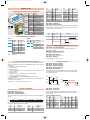
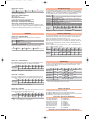
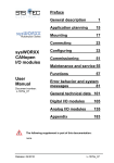
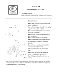
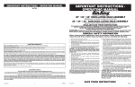
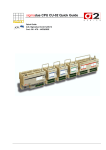
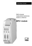
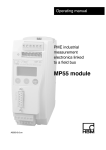
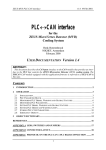
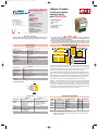
AI-02UI-uso-e
11-10-2011
15:37
Pagina 1
mod. IO-CB/AI-02UI-00
M.U. IO-CB/AI-02UI-3/11.05
Cod. J30-478-1AAI-02UI E
ISO9001 Certified
User
manual
Ascon Tecnologic S.r.l.
via Indipendenza 56,
27029 - Vigevano (PV), Italia
Tel.: +39 0381 69871,
Fax: +39 0381 698730
www.ascontecnologic.com
Contents
- Characteristics
- Functional Block Diagram
- PDOs used by the module
- Hardware Set-up
- Parameter configuration
- Commands
- Emergency messages
- Parameter Store/Restore
- Object Dictionary
E
CANopen I/O module
2 Universal Isolated
Analogue Inputs
mod. IO-CB/AI-02UI
2 isolated inputs for:
- Thermocouples
- RTD
- mA, mV, V linear inputs
- Potentiometers
- Custom sensors
APPLICABLE STANDARDS
WARNING
The AI-02UI module is suited for the CiA DS301 protocol [1] and implements the CiA DS 404
standard Device Profile, as far as the Analogue Input Function Block is concerned [2].
1) The product described in this manual should only be installed, operated and maintained by
qualified application programmers and software engineers who are familiar with automation
safety concepts and applicable national standards.
2) This product supports the Parameter defaults indicated by CiA standards, in addition, some parameters have a factory set (value present in the module when comes from the factory). The default
values can be loaded with the restore command, but after the restore, factory set values are lost.
Characteristics
Functional Block Diagram
Technical data
Accuracy at 25°C
Temperature coefficient
Cold junction compensation accuracy
Input impedance
Digital resolution
Input types
Conversion time
Overvoltage protection
NMR 50...60Hz
CMRR
±0.1% FS (RTD = ±0.05% FS)
0.005% FS/K
±0.5°K (between 0...50°C)
mA < 300Ω
mV > 100MΩ
V > 10kΩ
16 bit
TC J, K, L ,N, R, S, T - Pt100, Pt1000 - mA, mV, V
Potentiometer and other SW downloadable TCs
20 ms (RTD = 120 ms)
30 V
> 80 dB
> 100 dB
General
3 way isolation
Power supply
Power consuption
Dimensions
Weight
Safety regulations
EN61010-1
CE marking
2.5 kVp
24 Vdc; –15...+25%
2.5 W
L: 65; H: 110; W: 66
220 g
Isolation class II (50 Vrms),
Installation cathegory II,
Pollution degree 2
EN61131-2
3 way isolation diagram
Bus
Fieldbus
AI 1
Ch #1
AI 2
Ch #2
Logic
ADC
Field value
Status
Sensor type
Scaling 1 FV
Scaling 2 FV
Scaling 1 PV
Scaling 2 PV
Input offset
Autozero
Scaling
Delta
Lower
limit
Upper
limit
Process
value
Net PV
Physical
unit
Tare zero
Decimal
digits
Autotare
Transmit
∆
<
>
The analogue input function block describes, for each input channel, how field values are
converted to process values. The field values are converted to the real physical dimension
of the measured quantity, and the result is called "Process Value". The conversion from
Field Value to Process Value is generally described as a linear transformation.
This is defined by two pairs of field values and corresponding process values (Input Scaling 1
FV/Input Scaling 1 PV and Input Scaling 2 FV/Input Scaling 2 PV), called calibration point 1 and 2.
Non-linear transformation (e.g. for thermocouples and PT100 sensors) is possible, and is defined
within the parameter "Sensor Type". In this case the input scaling values are meaningless.
The calibration characteristic can be shifted by an additional "input offset" value.
Writing "1" on autozero will enable the zero offset value to be set so that the instantaneous
measured “process value” becomes zero. The tare-zero value works like the zero offset value,
but results in an additional "net process value". Writing "1" on autotare will enable the tare
zero value to be set so that the instantaneous measured “net process value” becomes zero.
The parameters "Span Start" and "Span End" define the process value validity range. If the
process value exceeds these limits it will be marked as "overflowed".
Power supply
2500Vp
PDOs used by the module
Environment
Operating
Temperature
-10...+65°C
Relative
5...95% non condensing
Humidity
Appropriate measures must
be taken against
humidity >85%
Mounting
Vertical, free air
Protection
IP20
Vibrations (3 axes) 10...57Hz 0.0375mm
57...150Hz 0.5g
Shock (3 axes)
15g, 11ms half sine
Storage
-40...+85°C
5...95% non condensing
For a short period, slight
condensation may appear
on the housing
TPDO
Properties
TPDO 1 COBID: 180h + NodeID
Transmission Type: 01h *
TPDO 2 COBID: 280h + NodeID
Transmission Type: 01h *
TPDO 3 COBID: 380h + NodeID
Transmission Type: 01h *
TPDO 4 COBID: 480h + NodeID
Transmission Type: 01h *
Mapped objects
NetPV1
AI status 1
NetPV2
AI status 2
NetPV1
NetPV2
Index
9140h
6150h
9140h
6150h
9140h
9140h
01h
01h
02h
02h
01h
02h
Sub-index
Cold junction Measure
2000h
01h
Note: * The Transmission Type is configurable:
01h is the factory set (value present in the modules when come from the factory);
FFh is the default value.
AI-02UI-uso-e
11-10-2011
15:37
Pagina 2
Hardware Set-up
Value
Hexadecimal rotary switches, service and I/O LEDs
LED
Status
ON
RUN Blinking
Single flash
OFF
ON
Single flash
ERR Double flash
Triple flash
OFF
ON
ST Blinking
Single flash
OFF
PWR ON
OFF
Top view
•
Hi
ide
nt s
Fro
•
Lo
Negative
screwdriver
0.4 x 2.5 mm
•
•
Meaning
Operational
Pre-operational (CANopen)
STOPPED
Device in RESET state
BUS OFF
Warning limit reached
Error Control Event
Sync Error (CANopen)
No error. Device working
DIAG Error
INIT and DIAG running
Baud rate setting
Module OK and ready
Module Power Supply ON
Module Power Supply OFF
Sensor Decimal
Value
type
digits
TCJ (default) 0x01
2
PT1000
TCK
0x02
2
PT100 2w
TCL
0x03
2
PT100 4w
TCN
0x04
2
0...10V
TCR
0x05
2
0...150mV
TCS
0x06
2
4...20mA
TCT
0x07
2
0...20mA
PT100 3w 0x1E
2
POT
(Sub-Index 1 channel 1, Sub-Index 2 channel 2)
Lo switch
AI Filter Type defines the type of filter to be applied to FV, AI Filter Constant defines
the iteration index. For both entries, subindex 01 refers to module channel 1 and
subindex 02 refers to module channel 2.
Value
0
1
2
3
4
5
6*
7
8
Description
No filter
1
Operation
ValueN = ValueN-1 +
Moving average
Node ID
Baud rate
kbps
20
50
100
125
250
500
800
1000
Input - ValueN-1
Filter Constant
N
Hi
Lo
Valid ID Node
switch switch
0
1
01h (address 1)
0
2
02h (address 2)
7
F
7Fh (address 127D) *
Bus length
m
2500
1000
500
500
250
100
50
25
Decimal
digits
2
2
2
3
3
3
3
3
Index 61A0h – AI Filter Type
Index 61A1h – AI Filter Constant
Bit Rate and Node ID configuration
Bit rate
Sensor
type
0x21
0x24
0x25
0x2A
0x2F
0x33
0x34
0x78
2
Repeating average Value =
1
InputN
N
N depends on Filter Constant
Module specific parameters
Index 2000h – Cold Junction Measure
Temperature of the cold junction, measured on the module’s terminal block.
Available through TPD04.
Index 2005h – 50/60 Hertz Input Filter
Filter against the Vac power line frequency
Note: * Default value
Index 3000h – Node Address
Current Module Node ID - Read only access
Index 3001h – Baudrate
Current Module Bit rate - Read only access
Procedure for Node ID and Bit Rate configuration
Scaling input variables
The HI and LO hexadecimal rotary swithches set the module’s Bit Rate and CAN Node ID.
During the configuration, the module must be off line and the CAN bus must be physically
disconnected.
To configure the module, follow the procedure:
1 Turn the Power OFF
2 Set the HI switch to “F”
3 Select the desired Bit Rate value by setting the LO switch following the table
(e.g. “8” for 1 Mbps)
4 Turn the Power ON
5 Shift the HI switch to “E” (all the module service LEDs should flash)
6 Turn the Power OFF. Now configure Node ID
7 Set the HI and LO switches to the desired valid Node ID following the table
8 Turn the Power ON.
Alternatively, at step 7 set the value 00h. Then, at the next Power ON, the last valid stored
value will be resumed as Node ID.
Default values:
Bit Rate = 500 kbps, Node ID = 127D
Index 9120h – AI Input Scaling 1FV
Index 9121h – AI Input Scaling 1PV
Index 9122h – AI Input Scaling 2FV
Index 9123h – AI Input Scaling 2PV
Index 9124h – AI Input Offset
As regards linear inputs, the above variables allow the scale of the physical input
to be changed and the desired physical unit to be assigned to this input. In addition, an offset can be added.
PV
Offset
PV2
Span
Measure
PV1
FV1
1
2
Negative
overload
FV2 FV
3
4
Positive
overload
Index 9148h – AI Span start
Index 9149h – AI Span end
Parameter configuration
Index 6110h - AI Sensor type
Index 6131h - AI Physical Unit PV
Index 6132h - AI Decimal Digits PV
These two variables take into account the validity of the span values, indicating
possible overloads and limiting the measure in correspondence of the extreme
points of the span.
The AI Physical Unit PV assigns SI units and prefixes to the process value, with the following
structure:
Span programmed values (°C)
31
MSB
24 23
Prefix
16 15
SI Numerator
8 7
SI Denominator
0
Reserved
LSB
Physical units and prefixes are coded according to CiA standard [3]. Within the DS404
profile, some additional physical units are specified:
Code
55h
56h
A1h
A2h
Physical unit
m/s
Nm
at
mmH2O
Code
A3h
A4h
ABh
ACh
Physical unit
mmHg
atm
PSI
°F
Input
TCJ
TCK
TCL
TCN
TCR
TCS
TCT
Span
Start
-210°C
-200°C
-200°C
0°C
0°C
0°C
-200°C
Span
End
1200°C
1372°C
600°C
1300°C
1600°C
1760°C
400°C
Input
LO
Range
PT100
PT1000
0...10V
0
0...150mV 0
4...20mA 0
0...20mA 0
POT
0
HI
Range
10.5
155
21
21
100
Span
Start
-200°C
-200°C
0V
0mV
4mA
0mA
0%
Span
End
600°C
600°C
10V
150mV
20mA
20mA
100%
AI-02UI-uso-e
11-10-2011
15:37
Pagina 3
Index 6150h – AI Status
bit 7 – 3
2
Reserved Negative overload
Emergency messages
1
Positive overload
0
Not valid (e.g. sensor break)
Index 9138h – Tare Zero
Tare value to be subtracted from PV.
Index 6114h – AI ADC Sample Rate
ADC acquisition time.
Index 6F20h – Life Counter
A counter that increments at each new generated sample.
Index 9143h – AI Interrupt Delta NetPV
Index 9144h – AI Interrupt Lower Limit Net PV
Index 9145h – AI Interrupt Upper Limit Net PV
The last the variables relate to the asynchronous mode of transmission of a PDO
(transmission type 255). A comparison is made with the mapped Net PV value and
a transmission is initiated asynchronously when any of the limits is reached.
The module automatically sends emergency messages including error codes. The communication errors are descrided in CiA DS301 [1]. The error codes are expressed as a DEVICE SPECIFIC ERROR type of code, one for each channel: 0xFF01 for channel 1 and 0xFF02 for channel 2.
The codes indicating a specific condition are also inserted, following the table below:
Error code Error
0000000000 No error –This code is generated when exiting an error contidion, to notify the
end of one of the error states
0000000001 Error No Valid Calib – An attempt to change the state of a input channel not
properly calibrated to “operating”
0000000002 Error No Config – An attempt to change the state of a input channel with a non
valid Sensor Type to “operating”
0000000006 Error No Command – Invalid command received
0000000007 Error Wrong Command – An attempt to execute a command from an illegal state
0000000008 Error Wrong Assignment – An attempt to assign a parameter from an illegal state
0
1
2
3
4
5
6
7
Emergency
0xh1
FFh
21h
00h
00h
00h
0Eh
00h
Message
COB – ID = [entry 1014h] + NodeID
Error
Notes: [1] x =1 for channel 1, 2 for channel 2
Commands
Parameter Store/Restore
Index 6112h – AI Operating Mode
Determines the operating state of the two input channels according to the
following values:
00h
Initialising (default)
01h
Operating
0Ah
Custom linearisation table assignment
Index 6160h – AI Control Byte
Enables (1) or disables (0) some of the commands accepted by the module:
Bit
7–3
1 = active Reserved
2
Auto-tare
1
Auto-zero
0
Auto-calibration
This module allows parameters to be saved in a non volatile memory. In order to avoid
storing parameters by mistake, storage is only executed when a specific signature is
written to the appropriate subindex. The signature is “save”.
Similarly, the default values of parameters, according to the communication or device
profile, are restored. On receipt of the correct signature in the appropriate subindex, the
device restores the default parameters and then confirms the SDO transmission. The
signature is “load”.
The new configuration becomes active after a reset, i.e. after a “Power OFF/Power ON
cycle” or an NMT “Reset Node” message.
Byte
0
1
2
3
4
5
6
7
22h
10h
10h
73h
61h
76h
65h
01h
Store
Parameter
s
a
v
e
COB – ID = 600h + NodeID
22h
11h
10h
6Ch
6Fh
61h
64h
01h
Restore
Parameter
l
o
a
d
COB – ID = 600h + NodeID
Index 6111h – AI Autocalibration
While in initialisation mode, the module can execute an autocalibration procedure
upon receipt of an SDO containing the “cali” signature in the data field.
Byte
0
1
2
3
4
5
6
7
22h
11h 61h 0xh1
63h
61h 6Ch 69h
Write request
c
a
l
i
COB – ID = 600h + NodeID
Notes: [1] x = 1 for channel 1, x = 2 for channel 2
SDO Messages
The entries of a device Object Dictionary are accessed trough SDO (Service Data Object)
messages. The basic SDO messages are as follows, as based on the Client – Server
request and response model:
Byte
Read request
Read response
Index 6125h – AI Autozero
Upon receipt of an SDO containing the “zero” signature in the data field, the module modifies the AI Input Offset in such a way that the AI Input PV becomes zero.
Byte
0
1
2
3
4
5
6
7
22h
25h 61h 0xh1
7Ah
65h 72h 6Fh
Write request
z
e
r
o
COB – ID = 600h + NodeID
Write request
Write response
0
40h
4xh *
22h
60h
1
2
3
4
5
6
Sub-Index
Reserved
COB – ID = 600h + NodeID
Index
Sub-Index
Data
COB – ID = 580h + NodeID
Index
Sub-Index
Data
COB – ID = 600h + NodeID
Index
Sub-Index
Reserved
COB – ID = 580h + NodeID
7
Index
* This code is type dependant.
Please refer to the CIA DS301 Profile for more details.
Notes: [1] x =1 for channel 1, x = 2 for channel 2
Index 6139h – AI Autotare
Writing a signature value of “tara” to this object causes the AI Tare Zero to be modified in such a way that the actual AI Net PV becomes zero.
Byte
0
1
2
3
4
5
6
7
22h
39h 61h 0xh1
74h
61h 72h 61h
Write request
t
a
r
a
COB – ID = 600h + NodeID
Notes:
[1]
x =1 for channel 1, x = 2 for channel 2
Reference documents
List of CiA documents to which the user should refer:
[1] CiA DS301 - CANopen Application Layer and Communication Profile
[2] CiA DS404 - CANopen Device Profile: Measuring Devices and Closed-Loop Controllers
[3] CiA DRP303-2 – Representation of SI Units and Prefixes
Accessories, Spare Parts and Warranty
Power Supply 45W 24Vdc 2A
Power Supply 120W 24Vdc 5A
Additional Terminal Block 2x11
Female Plug 11 Screw clamp
Female Plug 11 Spring clamp
RJ45 terminated cable 14cm
RJ45 terminated cable 22cm
CAN termination Adapter
AP-S2/AL-DR45-24
AP-S2/AL-DR120-24
AP-S2/TB-211-1
AP-S2/SPINA-V11
AP-S2/SPINA-M11
AP-S2/LOCAL-BUS76
AP-S2/LOCAL-BUS152
AP-S2/TERM-CAN
Warranty: 3 years excluding defects due to improper use
AI-02UI-uso-e
11-10-2011
15:37
Pagina 4
Object Dictionary structure (with default values)
A
In order to configure the module, it is necessary to connect it to a PC with the CAN interface and the superivisory software installed. The configuration can be obtained by
writing the desired values to the module’s variables listed in the Object Dictionary.
Index Sub
(hex) Index
1000
1001
1003
1005
1006
1007
1008
1009
100A
100C
100D
1010
00h
01h
1011
00h
01h
1014
1015
1017
1018
00h
01h
1200
1800
00H
01h
02h
03h
04h
05h
1801
00h
01h
02h
03h
04h
05h
1802
00h
01h
02h
03h
04h
05h
1803
00h
01h
02h
03h
04h
05h
1A00
00h
01h
02h
1A01
00h
01h
02h
1A02
00h
01h
1A03
00h
01h
02h
2000
00h
01h
2005
3000
3001
3500
00h
01h
02h
6110
00h
01h
02h
6111
00h
01h
02h
6112
00h
01h
02h
6114
00h
01h
02h
6125
00h
01h
02h
Object
Name
VAR
VAR
ARRAY
VAR
VAR
VAR
VAR
VAR
VAR
VAR
VAR
ARRAY
VAR
VAR
ARRAY
VAR
VAR
Device Type
Error Register
Predefined error field
COB-ID SYNC
Communication cycle period
Synchrounous window length
Manufacturer Device Name
Manufacturer Hardware Version
Manufacturer Software Version
Guard Time
Life Time Factor
Store Parameters
Largest subindex supported
Save all parameters
Restore Default Parameters
Largest subindex supported
Restore all default parameters
VAR
VAR
VAR
RECORD
VAR
VAR
RECORD
RECORD
VAR
VAR
VAR
VAR
VAR
VAR
RECORD
VAR
VAR
VAR
VAR
VAR
VAR
RECORD
VAR
VAR
VAR
VAR
VAR
VAR
COB-ID EMCY
Inhibit Time EMCY
Producer heartbeat time
Identity Object
Number of entries
Vendor ID
Server SDO Parameters
1st Transmit PDOComm Param.
Largest subindex supported
COB-ID used
Transmission type
Inhibit time
Reseved
Event timer
2nd Transmit PDOComm Param.
Largest subindex supported
COB-ID used
Transmission type
Inhibit time
Reseved
Event timer
3rd Transmit PDOComm Param.
Largest subindex supported
COB-ID used
Transmission type
Inhibit time
Reseved
Event timer
RECORD
VAR
VAR
VAR
VAR
VAR
VAR
RECORD
VAR
VAR
VAR
RECORD
VAR
VAR
VAR
RECORD
VAR
VAR
RECORD
VAR
VAR
VAR
ARRAY
VAR
VAR
VAR
VAR
VAR
4th Transmit PDOComm Param.
Largest subindex supported
COB-ID used
Transmission type
Inhibit time
Reseved
Event timer
1st Transmit PDOMapping
No. of mapped application obj
Net PV1
AI status Ch 1
2nd Transmit PDOMapping
No. of mapped application obj
Net PV2
AI status Ch 2
3rd Transmit PDOMapping
No. of mapped application obj
Net PV1
4th Transmit PDOMapping
No. of mapped application obj
Cold Junction Measure
ARRAY
VAR
VAR
VAR
ARRAY
VAR
VAR
VAR
ARRAY
VAR
VAR
VAR
ARRAY
VAR
VAR
VAR
ARRAY
VAR
VAR
VAR
ARRAY
VAR
VAR
VAR
Out of Range mode
Number of entries
Ch1 Out of Range mode
Ch2 Out of Range mode
AI Sensor Type
Number of entries
AI Sensor Type ch1
AI Sensor Type ch2
AI Autocalibration
Number of entries
AI Autocalibration ch1
AI Autocalibration ch1
AI Operating Mode
Number of entries
AI Operating Mode ch1
AI Operating Mode ch2
AI ADC Sample Rate
Number of entries
AI ADC Sample Rate ch1
AI ADC Sample Rate ch2
AI Autozero
Number of entries
AI Autozero ch1
AI Autozero ch2
Cold Junction Temperature
Number of entries
Cold Junction Measure
50/60 Hz Input Filter
Node Address
Node Baudrate
Default
[hex]
00020194
00
00000000
00000080
00000000
00000000
“02UI”
“1.00”
“1.00”
0000
00
01
03
01
01
80+NodeID
0000
07D0
01
000000E9
Type
UNSIGNED32
UNSIGNED8
UNSIGNED32
UNSIGNED32
UNSIGNED32
UNSIGNED32
Vis-String
Vis-String
Vis-String
UNSIGNED16
UNSIGNED8
UNSIGNED32
UNSIGNED8
UNSIGNED32
UNSIGNED32
UNSIGNED8
UNSIGNED32
UNSIGNED32
UNSIGNED16
UNSIGNED16
Identity (23h)
UNSIGNED8
UNSIGNED32
PDOCommPar (20h)
UNSIGNED8
UNSIGNED32
UNSIGNED8
UNSIGNED16
UNSIGNED8
0000
UNSIGNED16
PDOCommPar (20h)
05
UNSIGNED8
280+NodeID UNSIGNED32
FF *
UNSIGNED8
0000
UNSIGNED16
UNSIGNED8
0000
UNSIGNED16
PDOCommPar (20h)
05
UNSIGNED8
380+NodeID UNSIGNED32
FF *
UNSIGNED8
0000
UNSIGNED16
UNSIGNED8
0000
UNSIGNED16
05
180+NodeID
FF *
0000
05
480+NodeID
FF *
0000
0000
02
91400120
61500108
02
91400220
61500208
02
91400120
01
20000110
00000000
01
00
7F
06
2
0
0
02
01
01
02
02
00
00
02
00004E20
00004E20
02
PDOCommPar (20h)
UNSIGNED8
UNSIGNED32
UNSIGNED8
UNSIGNED16
UNSIGNED8
UNSIGNED16
PDOMapping (21h)
UNSIGNED8
UNSIGNED32
UNSIGNED32
PDOMapping (21h)
UNSIGNED8
UNSIGNED32
UNSIGNED32
PDOMapping (21h)
UNSIGNED8
UNSIGNED32
PDOMapping (21h)
UNSIGNED8
UNSIGNED32
UNSIGNED32
INTEGER16
UNSIGNED8
INTEGER16
UNSIGNED8
UNSIGNED8
UNSIGNED8
UNSIGNED8
UNSIGNED8
UNSIGNED8
UNSIGNED8
UNSIGNED16
UNSIGNED8
UNSIGNED16
UNSIGNED16
UNSIGNED32
UNSIGNED8
UNSIGNED32
UNSIGNED32
UNSIGNED8
UNSIGNED8
UNSIGNED8
UNSIGNED8
UNSIGNED32
UNSIGNED8
UNSIGNED32
UNSIGNED32
UNSIGNED32
UNSIGNED8
UNSIGNED32
UNSIGNED32
Acc.
Attr.
RO
RO
RO
RW
RW
RW
const
const
const
RW
RW
MO
M
M
O
O
O
O
O
O
O
O
O
O
RO
RW
RW
RO
RW
O
RW
RW
RW
O
O
O
M
Index Sub
(hex) Index
6131
00h
01h
02h
6132
00h
01h
02h
6139
00h
01h
02h
6150
00h
01h
02h
6160
00h
01h
02h
61A0
RO
RO
00h
01h
02h
M
RO
RW
RW
RW
RW
RW
61A1
00h
01h
02h
6F20
00h
01h
02h
M
RO
RW
RW
RW
RW
RW
9100
00h
01h
02h
9120
00h
01h
02h
M
RO
RW
RW
RW
RW
RW
9121
00h
01h
02h
9122
00h
01h
02h
M
RO
RW
RW
RW
RW
RW
9123
00h
01h
02h
M
9124
00h
01h
02h
RO
RO
RO
M
9130
00h
01h
02h
RO
RO
RO
M
9138
00h
01h
02h
RO
RO
M
9140
RO
RO
RO
00h
01h
02h
O
RO
RO
RW
RO
RO
9143
O
O
O
00h
01h
02h
9144
C
RO
RW
RW
00h
01h
02h
9145
O
RO
RW
RW
00h
01h
02h
9148
O
WO
WO
00h
01h
02h
9149
O
00h
01h
02h
RO
RW
RW
Object Name
Default
[hex]
ARRAY
VAR
VAR
VAR
ARRAY
VAR
VAR
VAR
ARRAY
VAR
VAR
VAR
ARRAY
VAR
VAR
VAR
ARRAY
AI Physical Unit PV
Number of entries
AI Physical Unit PV ch1
AI Physical Unit PV ch2
AI Decimal Digits PV
Number of entries
AI Decimal Digits PV ch1
AI Decimal Digits PV ch2
AI AutoTare
Number of entries
AI AutoTare ch1
AI AutoTare ch2
AI Status
Number of entries
AI Status ch1
AI Status ch2
AI Control Byte
UNSIGNED32
02
UNSIGNED8
002D0000 UNSIGNED32
002D0000 UNSIGNED32
UNSIGNED8
02
UNSIGNED8
02
UNSIGNED8
02
UNSIGNED8
UNSIGNED32
02
UNSIGNED8
UNSIGNED32
UNSIGNED32
UNSIGNED8
02
UNSIGNED8
00
UNSIGNED8
00
UNSIGNED8
UNSIGNED8
VAR
VAR
VAR
ARRAY
VAR
VAR
VAR
ARRAY
VAR
VAR
VAR
ARRAY
VAR
VAR
VAR
ARRAY
VAR
VAR
VAR
ARRAY
VAR
VAR
VAR
ARRAY
VAR
VAR
VAR
ARRAY
Number of entries
AI Control Byte ch1
AI Control Byte ch2
AI Filter Type
Number of entries
AI Filter Type ch1
AI Filter Type ch2
AI Filter Constant
Number of entries
AI Filter Constant ch1
AI Filter Constant ch2
Life Counter
Number of entries
Life Counter ch1
Life Counter ch2
AI Input FV
Number of entries
AI Input FV ch1
AI Input FV ch2
AI Input Scaling 1 FV
Number of entries
AI Input Scaling 1 FV ch1
AI Input Scaling 1 FV ch2
AI Input Scaling 1 PV
Number of entries
AI Input Scaling 1 PV ch1
AI Input Scaling 1 PV ch2
AI Input Scaling 2 FV
02
VAR
VAR
VAR
ARRAY
VAR
VAR
VAR
ARRAY
VAR
VAR
VAR
ARRAY
VAR
VAR
VAR
ARRAY
VAR
VAR
VAR
ARRAY
VAR
VAR
VAR
ARRAY
VAR
VAR
VAR
ARRAY
Number of entries
AI Input Scaling 2 FV ch2
AI Input Scaling 2 FV ch2
AI Input Scaling 2 PV
Number of entries
AI Input Scaling 2 PV ch1
AI Input Scaling 2 PV ch2
AI Input Offset
Number of entries
AI Input Offset ch1
AI Input Offset ch2
AI input PV
Number of entries
AI input PV ch1
AI input PV ch2
AI Tare Zero
Number of entries
AI Tare Zero ch1
AI Tare Zero ch2
AI Net PV
Number of entries
AI Net PV ch1
AI Net PV ch2
AI Interrupt Delta Net PV
Number of entries
AI Interrupt Delta Net PV ch1
AI Interrupt Delta Net PV ch2
AI Interrupt Lower Limit Net PV
VAR
VAR
VAR
ARRAY
VAR
VAR
VAR
ARRAY
VAR
VAR
VAR
ARRAY
VAR
VAR
VAR
Number of entries
AI Interrupt Lower Limit Net PV ch1
AI Interrupt Lower Limit Net PV ch2
AI Interrupt Upper Limit Net PV
Number of entries
AI Interrupt Upper Limit Net PV ch1
AI Interrupt Upper Limit Net PV ch2
AI Span Start
Number of entries
AI Span Start ch1
AI Span Start ch2
AI Span End
Number of entries
AI Span End ch1
AI Span End ch2
02
00
00
02
01
01
02
00
00
02
02
02
02
02
02
00000000
00000000
02
02
00000000
00000000
02
02
00000001
00000001
02
FFFFB1E0
FFFFB1E0
02
0001D4C0
0001D4C0
02
FFFFB10
FFFFB10
02
0001D4C0
0001D4C0
Type
Acc. MO
Attr.
O
RO
RW
RW
O
RO
RW
RW
O
RO
WO
WO
O
RO
RO
RO
O
UNSIGNED8
UNSIGNED8
UNSIGNED8
UNSIGNED8
UNSIGNED8
UNSIGNED8
UNSIGNED8
UNSIGNED8
UNSIGNED8
UNSIGNED8
UNSIGNED8
UNSIGNED8
UNSIGNED8
UNSIGNED8
UNSIGNED8
INTEGER32
UNSIGNED8
INTEGER32
INTEGER32
INTEGER32
UNSIGNED8
INTEGER32
INTEGER32
INTEGER32
UNSIGNED8
INTEGER32
INTEGER32
INTEGER32
RO
WO
WO
UNSIGNED8
INTEGER32
INTEGER32
INTEGER32
UNSIGNED8
INTEGER32
INTEGER32
INTEGER32
UNSIGNED8
INTEGER32
INTEGER32
INTEGER32
UNSIGNED8
INTEGER32
INTEGER32
INTEGER32
UNSIGNED8
INTEGER32
INTEGER32
INTEGER32
UNSIGNED8
INTEGER32
INTEGER32
INTEGER32
UNSIGNED8
INTEGER32
INTEGER32
INTEGER32
RO
RW
RW
UNSIGNED8
INTEGER32
INTEGER32
INTEGER32
UNSIGNED8
INTEGER32
INTEGER32
INTEGER32
UNSIGNED8
INTEGER32
INTEGER32
INTEGER32
UNSIGNED8
INTEGER32
INTEGER32
O
RO
RW
RW
O
RO
RW
RW
O
RO
RO
RO
O
RO
RO
RO
O
RO
RW
RW
O
RO
RW
RW
O
O
RO
RW
RW
O
RO
RW
RW
O
RO
RO
RO
O
RO
RW
RW
O
RO
RO
RO
O
RO
RW
RW
O
RO
RW
RW
O
RO
RW
RW
O
RO
RW
RW
O
RO
RW
RW
O
RO
RO
RO
O
RO
WO
WO
*
The factory set (value present in the modules when new) for the transmission
type is: 01h.