1
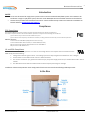
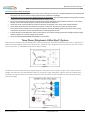
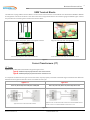
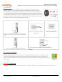
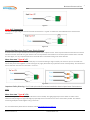
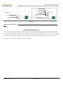
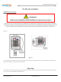
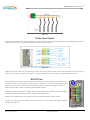
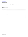
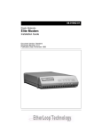
BRULTECH RESEARCH INC GEM Quick Guide 3-Phase Basic Installation Manual For Three Phase System Installation Only! DOC Code: GEM-3QG Ver 1.0 This manual is an installation brief. For more detailed information, download a more detailed version from our site: www.brultech.com/software Brultech Research Inc 2 Introduction NOTE: Do not use this manual for single phase systems such as common residential 120V/240V systems. If the GEM is to be installed on a single or split phase system, then refer to the GEM-QGD document available from the site listed below. This document provides brief installation instructions. A more detailed and up to date User’s Manual is available from Brultech website: www.brultech.com/software Compliance FCC Compliance The GreenEye Monitor has been tested to Comply with FCC Standards for Home and Office Use. This device complies with Part 15 of the FCC Rules. Operation is subject to the following two conditions: (1) this device may not cause harmful interference, and (2) this device must accept any interference received, including interference that may cause undesired operation. Wireless Versions: Contains FCC ID: OUR-XBEE2 (USA) (Wireless Versions Only) Contains Model XBee® ZNet 2.5 Radio, IC: 4214A-XBEE2 (Canada) May Contain Roving Networks WiFly Module FCC ID: T9J-RN171 May Contain FCC ID: AZYHF-A111 UL and CSA Compliance The GREENEYE MONITOR (GEM) operates as a “Class II” low voltage device. This requires that all connections to the GEM comply with the following: 1. Voltage from external signal must be “Low Voltage” (less than 50V) and galvanic isolated from “line” voltages 2. All connections to the GEM must be “Class II” double insulated 3. The current transformer (CT), potential transformer (PT) and power supply must be UL/c certified when used in USA or Canada 4. The GEM device must NOT be installed inside an electrical panel possessing line voltages. Installation of the GreenEye Monitor must comply with all local codes and must be installed by qualified personnel. In the Box 2 © Brultech Research Inc www.brultech.com Brultech Research Inc 3 GEM Connection Layout 1 - The outlined section in the “1” circle of Figure 1 shows where the current transformer leads connect. Refer to “Current Transformers (CT)” section for more information. 2 – The two terminal blocks is where connection from a pulse signal connects. See “Pulse Count Inputs” chapter for more information 3 – Is the 3.5mm jack for connection to the Potential Transformer (PT). The PT senses the line voltage and should be plugged into a receptacle as near as possible to the electrical panel for best accuracy 4 – This is not a USB connection! This mini USB jack may be used as an alternate power supply or PT signal jack. 5 - The 5VDC power supply plugs into an outlet. The power supply cable then plugs into the barrel jack. 6 – This auxiliary terminal block provides +3.3VDC or +5VDC supply for auxiliary devices. 7 – The “1-Wire” bus connection for temperature sensors. 8 – The RS-232 communication terminal block 13 – Status LEDs. The “System” LED (left) provides GEM operational status while the “Communication” LED (right) shows the status of the communication module. Figure 1 Safety All safety rules described below must be obeyed. Please read carefully before proceeding with the installation of the GreenEye Monitor and associated current transformer. Brultech Research Inc. assumes no liability for failure to comply with the safety guidelines described below. The GREENEYE MONITOR (GEM) operates as a “Class II” low voltage device. This requires that all external connected signals be low voltage (<50V) and provided by Class II approved power supply and sensors. All of our power supplies are UL, CSA or UL/c approved for use in USA and Canada. Most of our current transformers (CT) are UL/c listed. No direct line connections to the GEM are allowed. All signals must be galvanic isolated from the power-line. WARNING ! Read All Of The Safety Rules Before Installing! Never install the GEM inside an electrical panel. A separate “low voltage” panel may be used if required. The GREENEYE MONITOR (GEM) installation requires the installation of current transformers (CT) installed inside the electrical service panel. This portion of the installation MUST be performed by a qualified electrician or individual. The installer must follow all local safety codes and use proper safety practices and equipment. The qualified installer must be aware that main panels may still contain dangerous voltage levels even though the main breaker is in the “OFF” position. Cont’d Next Page 3 © Brultech Research Inc www.brultech.com Brultech Research Inc 4 The rules listed below MUST be obeyed! Any work performed inside the electrical panel must be done by an electrician or qualified individual. This individual will be familiar with the local electrical code and perform the installation accordingly. NEVER install the GreenEye Monitor (GEM) inside the electrical panel. Only low voltage (12VAC or less) galvanic isolated connections are to be made to the GREENEYE MONITOR (GEM) terminals. The current transformer (CT) leads must exit the electrical panel through an appropriate box connector, strain relief or bushing. The CT leads must be properly anchored on the outside of the panel. The portion of the CT leads inside the panel must not have any damage, cuts or wear to the outside insulation. The CT leads inside the panel must not have any splices or extension. The entire CT lead must exit the panel. The CT leads must be routed in such a way that its insulation will not be rubbing against live terminals. Care must be exercised not to pinch the CT leads especially when re-installing the panel cover. If panel voltages exceed 300V, then make sure that the CTs are rated for voltage greater than the highest panel voltage and that a proper PT is used for voltage measurement. Do not install the GREENEYE MONITOR (GEM) in a wet location. Three Phase (Polyphase) 4-Wire Wye(Y) System Most commercial and light industrial buildings will have three phase panels. Three phase (sometimes referred to as “polyphase”) is preferred for powering large motors such as those found in rooftop AC units, refrigeration units and machinery. The most common system is the 4-wire “Y” 120V/208V feed as shown in Figure 2 below. Figure 2 The GEM uses a unique method of monitoring the voltage of a three phase system. Typically, energy monitors require all three voltages to be monitored. The GEM simplifies matters by monitoring a single voltage phase. Figure 3 shows the simplicity of the installation. The voltage is obtained via a wall-transformer. Other PT solutions are also available that allow monitoring 3-phase systems up to 480V. Figure 3 4 © Brultech Research Inc www.brultech.com Brultech Research Inc GEM Terminal Blocks The GEM uses “spring loaded” terminal blocks. The wire to be inserted into the terminal block must be between 18AWG to 26AWG and stripped to a minimum of 10mm. If two wires must share a single terminal then the maximum gauge is 24AWG. Figure 4 shows the procedure for connecting the CT leads to the terminal block. Make sure the wire is of the proper gauge and stripped to 10mm Align the wire ends with the appropriate holes Press the spring lever with a flat screwdriver Insert the wire ends fully and release the lever Figure 4 Current Transformers (CT) CT Types Important: The GEM will accommodate two general types of CTs: Type A : Millivolt output proportional to the sensed current Type B : Milliamp output proportional to the sensed current It is important to determine the type of CT used so that it may be properly connected to the GEM. Figure 5 describes the difference between the two types and also lists various CT models for each type. Type A CT Type B CT SPLIT-60, SPLIT-100, SPLIT-200, SPLIT-400/600 Micro-40, SPLIT-30, Micro-50, Micro-80, Micro-100 Type A CT has an internal burden resistor. Type B CT has no internal burden resistor and uses the GEM’s built-in burden resistor connected between terminals 2 and 3. Figure 5 5 © Brultech Research Inc www.brultech.com 5 Brultech Research Inc CT Orientation The orientation specifies the direction that the CT is facing when installed on the circuit breaker conductor. The CT orientation is either facing toward or way from the breakers. Current transformers generally have a marking “K L” where “K” is the source (breaker) and “L” is the load. See Figure 6. All CTs should be installed with the arrow pointing away from the circuit breaker, toward the load “L”. Figure 7 shows the polarization arrow location for various CT models. The “Micro” CT does not have an arrow stamped on its casing. You must determine the imaginary arrow based on the top left diagram of Figure 7. Figure 6 Micro-40, Micro-50, Micro-80, Micro-100 There is no arrow stamped on the “Micro” CTs. The arrow is imaginary and based on the side that the CT leads exit the CT casing. SPLIT-60 The arrow is stamped on the bottom of the SPLIT-60 CT SPLIT-200 The arrow is stamped on the side of the SPLIT-200 CT SPLIT-100 The arrow is stamped on the bottom of the SPLIT-100 CT SPLIT-400/600 The arrow is stamped on the bottom of the SPLIT-400/600 CT Figure 7 CT Connection (3-phase) Each of the GEM’s 32 channels has a four point terminal block (see Figure 8). Each point is numbered 1-4. The numbers are not marked on the terminal block. You must presume the number “1” to “4” starting from the bottom as displayed in Figure 8. The type of CT used determines which of the four terminals the CT leads will be connected to. Figure 8 Type A CT Connection The diagram in Figure 9 shows the lead connection for a “Type A” CT. Make sure the solid black lead is connected to terminal “1”. 6 © Brultech Research Inc www.brultech.com 6 Brultech Research Inc 7 Figure 9 Type B CT Connection The diagram in Figure 9Figure 10 shows the lead connection for a “Type B” CT. Make sure the solid black lead is connected to terminal “2”. Figure 10 Connecting More than One CT on a Single Channel It is best to use one CT per channel when monitoring loads from a 3-phase service. There may be occasions where there is a need to monitor more than one load on a given channel. This can only be done if the loads are on the same phase and the same CT models are used. Again, it is very important that all CTs mounted with its orientation facing in the same direction. More than one “Type A” CT If only two “Type A” CTs are to be connected, they can connect according to Figure 11 (left). For three CTs you can use small wire nuts to daisy chain them together in series. See Figure 11 (right). Remember to pay attention to the CT lead polarity. The two ends of the CT chain then connects to CT terminals “1” and “4”. Figure 11 Important Safety Warning: The CT lead splices MUST be located outside the electrical panel even if wire nuts are used. More than two “Type B” CTs Connect the “Type B” CTs in parallel (must all be the same CT model). Use light gauge lamp cord or similar to create a short extension lead (see Figure 12 right side diagram) especially when more than two CTs are in connected in parallel. This enables connecting multiple CT leads together using a “wire nut”. For more information please refer to the latest manual www.brultech.com/software. 7 © Brultech Research Inc www.brultech.com Brultech Research Inc 8 Figure 12 Important Safety Warning: The CT lead splices MUST be located outside the electrical panel even if wire nuts are used. Potential Transformer The potential transformer (PT) is used to sample the power line voltage. Its function is to reduce the line voltage to safe levels and create “Class II” isolation between the power line and the GEM. The PT included in the GEM package is an AC wall transformer which must be connected to a 120VAC outlet as close as possible to the electrical panel monitored. The PT’s 12VAC connects to the GEM via a 3.5mm phone plug. When plugging the PT’s 3.5mm plug into the PT jack on the GEM, make sure the plug is fully inserted! Other PTs are available for other voltage potential such as 240VAC. 8 © Brultech Research Inc www.brultech.com Brultech Research Inc 9 Pre-Plan the Installation GEM Mounting Location WARNING ! NEVER Install the GREENEYE MONITOR (GEM) unit inside the Electrical Panel Determine the best mounting location for the GEM taking into consideration the length of the CT leads. Some CT models have longer leads than others. The two large main panel CTs such as SPLIT-100 or SPLIT-200 have longer leads than Micro-CTs do, so it may be preferable to locate the GEM at the opposite end of the panel feed from where the large CTs are installed. See Figure 13 Figure 13 It is also important to consider where the CT leads will be routed when choosing a location to mount the GEM. If mounted too far away, the CT leads may not reach the terminal strips 1-Wire Bus The “1-Wire” bus is used to connect up to eight temperature sensors. All sensors connect to the same three wires (bus), see Figure 14. The sensors may be DS18B20 or DS18S20 types. 9 © Brultech Research Inc www.brultech.com Brultech Research Inc 10 Figure 14 Pulse Count Inputs The GEM has four pulse count inputs (see Figure 15). Pulse counter #1 and #2 are totally isolated from the GEM ground and circuit. If using any of these inputs, a DC pulse signal between 3V and 24VDC is required. Figure 15 Pulse counters #3 and #4 are “dry” contact type counters. These inputs require switch contacts not connected to any power source, such as relay contacts or magnet switch contacts. Very low voltage from the circuit (5VDC) is used to complete the circuit. RS-232 Port Every GEM device comes with two RS-232 ports. The RS-232 port may be used to connect directly to an automation system, a “Serial to Ethernet” device such as “EtherPort” or to a serial to USB adaptor. Either of these ports may be used at the main communication gateway or simply to configure the GEM, the GEM’s (optional) WiFi module or the GEM’s (optional) XBee® module. The GEM is capable of being put in “Bridge Mode” which causes Com1 and Com2 to be linked together so that the RS-232 port can talk directly to a module on the opposite port. Connection to the RS-232 port is accomplished via terminal blocks #8 in the “layout” section. Typically only one RS-232 port would be used therefore there is only one common (GND) connection available. See Figure 16. Figure 16 10 © Brultech Research Inc www.brultech.com Brultech Research Inc 11 Channel Assignment Worksheet GEM CH # Load Description Breaker Number 1 2 3 4 5 6 7 8 9 10 11 12 13 14 15 16 17 18 19 20 21 22 23 24 25 26 27 28 29 30 31 32 Breaker Amps A A A A A A A A A A A A A A A A A A A A A A A A A A A A A A A A 11 © Brultech Research Inc www.brultech.com CT Model 120V 240V 1-CT 240V 2-CTs