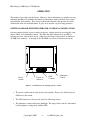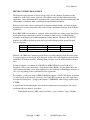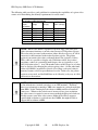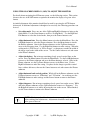
1
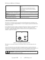
EDL Displays, Inc. 1300 Research Park Drive Dayton, Ohio 45432 (937) 429-7423 www.edldisplays.com Part Number: 3018-19-MAN-LCD, rev. 2, April 10, 2003 EDL Displays 3000 Series LCD Monitors Notice to Users The equipment described in this manual uses and generates radio frequency energy and can cause interference to other equipment if not installed and used in accordance with guidelines set forth here. This equipment is designed to meet requirements for Class B computing devices set forth in FCC Rules, Part 15, Subpart J, and requirements of the European Union for electromagnetic compatibility of equipment to be used in residential and light industrial environments (Directive 89/336/EEC, EN50081-1, EN50082-1). When used as recommended, radio frequency emissions from this equipment will fall within acceptable limits for residential and light industrial environments. Operation of this equipment in other environments could subject it to interference from other equipment. This manual provides guidelines for the safe and effective use of the equipment described. However, EDL Displays, Inc. makes no warranty concerning the suitability of this equipment for any particular use and explicitly disclaims any responsibility or liability for loss or damage that might result from its improper application. Knowledge of good practice as it relates to display devices and solid state electronics in general is necessary for the proper application of these guidelines, and this manual assumes such knowledge on the part of the reader. EDL Displays, Inc. has made every effort to ensure that information presented in this manual is complete and accurate. However, EDL Displays, Inc. cautions that this information often relates, of necessity, to a typical or exemplary situation. EDL Displays, Inc. explicitly disclaims any responsibility or liability for any loss or damage that might result from the use of this information in particular situations. EDL reserves the right to make changes to this manual at any time without obligation to provide notification of such changes. This manual is distributed under copyright. It may not be reproduced for commercial purposes, in whole or on part, without the written permission of EDL Displays, Inc. Limited Warranty EDL Displays, Inc. (hereinafter “EDL”) warrants that the products described herein will remain free from defects in material and workmanship for a period of two years from the date of delivery. EDL will, at its own expense, correct any such defect that might manifest itself and be properly reported during this period. EDL’s corrective action shall be limited to repair of the defect, or, at its discretion, replacement of the defective unit. In order to obtain the benefits of this warranty, it shall be the purchaser’s obligation to obtain prior authorization (in the form of an RMA number) from EDL for return of the product, and to provide for shipment of the product both to and from EDL’s repair facility. This warranty does not extend to damage caused by mishandling during shipping or to damage caused by misapplication or abuse (whether intentional or accidental) of the product or failure to follow EDL’s guidelines. This warranty is offered in lieu of any warranty concerning the suitability or fitness of this product for a particular application and is extended only to the original purchaser. The symbol at left, together with the word “warning,” is used throughout this manual to call special attention to information that is intended to help the user avoid personal injury and/or damage to equipment. The symbol at left, together with the word “note,” is used throughout this manual to call attention to supplementary information that might be of special interest or value to the user. Copyright © 2002 -ii- by EDL Displays, Inc. User’s Manual Table of Contents INTRODUCTION................................................................................................................... 1 FEATURES OF EDL 3018 AND 3019 LCD MONITORS ............................................................ 1 CONFIGURATION GUIDE ......................................................................................................... 1 INSTALLATION.................................................................................................................... 3 UNPACKING ........................................................................................................................... 3 CHECKING PACKAGE CONTENTS............................................................................................ 3 MOUNTING............................................................................................................................. 3 Rack Mounting .................................................................................................................. 3 Console or Panel Mounting .............................................................................................. 4 VESA Arm or Yoke Mounting ........................................................................................... 5 MAKING VIDEO INPUT CONNECTIONS ................................................................................... 6 MAKING POWER AND GROUND CONNECTIONS ...................................................................... 6 AC Power .......................................................................................................................... 6 DC Power.......................................................................................................................... 7 OPERATION .......................................................................................................................... 8 GETTING FAMILIAR WITH THE OPERATOR CONTROLS AND INDICATORS .............................. 8 SETTING UP THE VIDEO SOURCE ............................................................................................ 9 USING THE ON-SCREEN DISPLAY (OSD) TO ADJUST THE MONITOR.................................... 11 NAVIGATING THE ON-SCREEN MENU SYSTEM IN DETAIL ................................................... 12 Main Menu ...................................................................................................................... 12 Picture Submenu ............................................................................................................. 13 OSD Submenu ................................................................................................................. 14 Utility Submenu............................................................................................................... 15 Quick Menu ..................................................................................................................... 16 MAINTENANCE AND SERVICE ..................................................................................... 17 ROUTINE MAINTENANCE ..................................................................................................... 17 TROUBLE-SHOOTING ............................................................................................................ 17 LINE FUSE REPLACEMENT ................................................................................................... 18 BACKLIGHT REPLACEMENT .................................................................................................. 19 SERVICE AND SUPPORT ........................................................................................................ 19 APPENDIX A: VIDEO INPUT CONNECTOR PIN ASSIGNMENTS .......................... 20 APPENDIX B: VIDEO CABLE OPTIONS ....................................................................... 21 HD-15 TO HD-15 ................................................................................................................ 21 HD-15 TO 5 BNC ................................................................................................................ 21 APPENDIX C: TOUCHSCREEN SERIAL INTERFACE .............................................. 22 APPENDIX D: X-TERMINAL OPTION........................................................................... 23 INSTALLATION ..................................................................................................................... 23 RECOMMENDATIONS FOR SETUP OF THE X-TERMINAL ......................................................... 24 Copyright 2002 -iii- by EDL Displays, Inc. EDL Displays 3000 Series LCD Monitors APPENDIX E: IR REMOTE CONTROL OPTION......................................................... 25 APPENDIX F: OUTLINE AND MOUNTING DRAWINGS........................................... 26 APPENDIX G: TECHNICAL SPECIFICATIONS .......................................................... 30 MODEL 3018........................................................................................................................ 30 MODEL 3019........................................................................................................................ 31 Table of Figures Figure 1 -- Rear view of 3018/19 showing connectors............................................................. 6 Figure 2 – 3018/19 front view, showing operator controls....................................................... 8 Figure 3 – OSD Controls ........................................................................................................ 12 Figure 4 -- 3018/19 I/O panel showing fuse location ............................................................. 18 Figure 5 – Rear View 3018/3019 with X-terminal ................................................................. 23 Figure 6 – Optional Hand-held control unit............................................................................ 25 Figure 7 – Model 3018RM Outline Drawing (shown with X-terminal option) ..................... 26 Figure 8: 3018 Outline Drawing ............................................................................................. 27 Figure 9: 3019RM Outline Drawing....................................................................................... 28 Figure 10: 3019 Outline Drawing ........................................................................................... 29 Copyright © 2002 -iv- by EDL Displays, Inc. User’s Manual INTRODUCTION FEATURES OF EDL 3018 AND 3019 LCD MONITORS • • • • • • Screen diagonals of 18.1” and 19.0” High performance video controller/scaler common to all models. Full-range backlight dimming standard on all models Luminance stabilization circuit standard on all models Rugged enclosures suitable for rack, console panel, VESA arm or yoke mounting Options include touchscreens, DC power, more CONFIGURATION GUIDE A 3000 series monitor is specified using the model numbering scheme illustrated in the table below. The full model number consists of a base model number followed by a series of designators indicating options installed. Base Model Number 3018CM 3018RM 3018VM 3019CM 3019RM 3019VM Description 18.1” LCD monitor, 1280x1024, console/panel mount package 18.1” LCD monitor, 1280x1024, rack mount package 18.1” LCD monitor, 1280x1024, VESA arm or yoke mount package 19.0” LCD Monitor, 1280x1024, console/panel mount package 19.0” LCD Monitor, 1280x1024, rack mount package 19.0” LCD Monitor, 1280x1024, VESA arm or yoke mount package Copyright 2002 -1- by EDL Displays, Inc. EDL Displays 3000 Series LCD Monitors Options available for the 3000 series monitors are described in the table below. Power Supply Options 115 to 230VAC Input (85 to 264VAC, 47 to 66Hz and 400Hz), IEC receptacle 115 to 230VAC Input (85 to 264VAC, 47 to 66Hz and 400Hz), military receptacle 24VDC Input (-18VDC to +32VDC), screw terminal block Screen Overlay Options Strengthened glass, A-R coating, unbonded Strengthened glass, fine etch, unbonded Capacitive touchscreen, A-R etch, 88% transmissivity, unbonded, with serial controller Bonding of overlay to LCD panel Optional Add-on Modules X-terminal Operator Controls Options Front controls, including digital controls for OSD, analog luminance control and power switch Front controls, including digital controls for OSD, analog luminance control, but no power switch Remote control option IR remote controls for OSD Video cable options HD-15 to HD-15, 2m HD-15 to 5 BNC, 2m Copyright © 2002 -2- 3018CM 3019CM 3018RM 3019RM 3018VM 3019VM Std Std Std Opt Opt Opt Opt Opt Opt Std Std Std Opt Opt Opt Opt Opt Opt Opt Opt Opt Opt Opt Opt Std Std Std Opt Opt Opt Opt Opt Opt Opt Opt Opt Opt Opt Opt by EDL Displays, Inc. User’s Manual INSTALLATION This section describes the unpacking and installation of the monitor. UNPACKING Before unpacking, the shipping carton should be inspected for damage. Then, the carton should be carefully opened and the monitor removed. The monitor itself should be carefully inspected for shipping damage. If damage has occurred, the shipping carton and all packing materials should be saved for possible inspection by the shipping company, and the shipping company and EDL Displays should be notified immediately. NOTE: EDL recommends saving the packaging for re-use in case the monitor should ever have to be shipped to a new location. CHECKING PACKAGE CONTENTS All EDL monitors are supplied with a User’s Manual and with cables and other optional accessories as specified by the customer at the time of order. The contents of the package should be checked against the packing list to ensure that all items are present. MOUNTING Rack Mounting The 30xx-RM monitors are designed to be mounted without slides in an EIA 19” rack cabinet. The hole pattern on the monitor’s front panel allows mounting the unit on rack rails that have either a “Wide” or a “Universal” hole pattern. NOTE: About “Universal” vs. “Wide” hole spacings on EIA rack cabinet rails. The mounting rails that run vertically along the inside edges of the front and rear openings of EIA rack cabinets can be of two types. “Wide” rails have holes spaced 0.5” and 1.25” on centers, in a repeating pattern. These rails are prevalent in Europe. “Universal” rails have holes spaced 0.5” 0.625” and 0.625” on centers, in a repeating pattern. Thus the “Universal” rails have a hole pattern that contains the “Wide” pattern but provides an additional hole at the midpoint of the pattern. “Universal” rails are most prevalent in the U.S. Before installing the monitor in a rack, ensure that the following conditions for installation are met: Copyright 2002 -3- by EDL Displays, Inc. EDL Displays 3000 Series LCD Monitors • Adequate ventilation must be available within the rack cabinet to ensure that monitor is not exposed to ambient temperatures above 50°C. • The relative humidity of the air within and around the rack cabinet should not exceed 85%. • Following installation, there must be sufficient clearance around the ventilation holes in the monitor’s rear enclosure to allow good circulation. Whenever possible, avoid mounting the monitor in the uppermost part of the rack cabinet. • Power and earth ground should be accessible when the monitor is installed in the cabinet. NOTE: To provide maximum comfort for the user, the monitor should be mounted so that the top of the screen is at or slightly below eye level, and so that light from nearby windows, overhead fixtures, etc. does not reflect off the screen. Installation in the rack cabinet is easy and should proceed as follows: • Before positioning the monitor on the rack rails, identify the holes in the rails that will match up to the holes in the monitor’s panel and install clip nuts in those holes. Please refer to the appropriate outline drawing for the locations of the holes in the monitor panel. • If there is no access to the monitor from the rear of the cabinet following installation, power, ground and video connections should be made prior to installing the monitor on the rails. Please refer to the following sections of the manual for connection guidelines. • Position the monitor on the rails and run screws through the front panel holes into the pre-installed clip nuts. NOTE: The monitor must be positioned on the rack rails in such a way that the top and bottom edges of its panel fall midway between rail holes spaced 0.5”. Console or Panel Mounting The 30xx-CM monitors are designed for mounting on a console panel. Before installing the monitor on a panel, ensure that the following conditions for installation are met: Copyright © 2002 -4- by EDL Displays, Inc. User’s Manual • Adequate ventilation must be available within the console to ensure that monitor is not exposed to ambient temperatures above 50°C. • The relative humidity of the air within and around the console should not exceed 85%. • Following installation, there must be sufficient clearance around the ventilation holes in the monitor’s rear enclosure to allow good circulation. • Power and earth ground should be accessible when the monitor is installed in the console. Installation on a console panel should proceed as follows: • Refer to the appropriate outline and mounting drawings in Appendix F for dimensions and locations of mounting holes. • Make a rectangular cut-out in the console panel to accommodate that part of the monitor’s enclosure that projects backward behind its front panel. The monitor must drop into this cut-out in such a way that the back surface of its front panel rests against the front surface of the console panel on all four sides. • Drill holes around the periphery of the cut-out just made in the console panel. The holes should be located in such a way that they will align with the mounting holes on the monitor. • Power, ground and video connections can be made prior to installing the monitor in the console panel, or afterwards, if there is sufficient access to the rear of the console. Assess the situation before making final installation of the monitor. • Position the monitor in the console panel cut-out and install screws through the mounting holes to secure the monitor. NOTE: To provide maximum comfort for the user, the monitor should be mounted so that the top of the screen is at or slightly below eye level, and so that light from nearby windows, overhead fixtures, etc. does not reflect off the screen. VESA Arm or Yoke Mounting The 30xx-VM monitors are designed for mounting to an articulated arm that provides a mounting flange with a VESA standard hole pattern. Please refer to mounting instructions supplied with the VESA arm to be used. Copyright 2002 -5- by EDL Displays, Inc. EDL Displays 3000 Series LCD Monitors MAKING VIDEO INPUT CONNECTIONS All EDL 3000 series monitors accept analog RGB video signals at an HD-15 connector. When connecting the monitor to an analog signal source, it is necessary to use a cable that terminates on the monitor end with an HD-15 connector that mates to the monitor’s connector, and on the source end with an HD-15 connector or with some combination of three to five BNC connectors, as appropriate to the source. (See cable descriptions in the appendices for details. Cables are available from EDL.) Provided the correct cable is used, the monitor will automatically sense and adapt to the sync type (sync-on-green, composite separate sync, or separate horizontal and vertical syncs). Please refer to the following figure for location of the HD-15 connector on the monitor’s rear panel. VIDEO IN POWER SERIAL FUSE 85-265 VAC 47- 440Hz VIDEO IN POWER SERIAL FUSE 85-265 VAC 47-440HZ Figure 1 -- Rear view of 3018/19 showing connectors MAKING POWER AND GROUND CONNECTIONS AC Power A monitor equipped for operation on AC power should be connected to a single-phase power source providing 115 to 230VAC nominal (85 to 264VAC) at 47 to 66Hz, or 400Hz. Copyright © 2002 -6- by EDL Displays, Inc. User’s Manual Connection is made by way of an IEC power cord at the monitor’s power input connector, or by way of a military style connector, when that option is specified. (See figure above for the location of the input connector on the monitor’s rear panel.) WARNING: To ensure against fire or shock hazards, the monitor chassis should be connected to an earth ground by a path that is independent of the power cord. While the AC power cord provides a ground wire, the power cord ground can be defeated by use of an extension cord or 3-prong to 2prong AC adapter, and it can be rendered ineffective by improper wiring of the AC receptacle. NOTE: To minimize ground loop induced “noise” on the video inputs, it is good practice to connect the monitor’s AC power cord to the same receptacle that supplies power to the video source. DC Power A monitor equipped for operation from a DC power source should be connected to the DC main using UL approved #10 stranded wire. The wire should use properly color-coded insulation. Copyright 2002 -7- by EDL Displays, Inc. EDL Displays 3000 Series LCD Monitors OPERATION The monitor is pre-aligned at the factory. However, minor adjustments are usually necessary following installation to optimize the monitor’s performance with a particular video source and particular video formats. This section of the manual describes the operator accessible controls that allow for such adjustment. It goes on to describe a typical setup procedure. GETTING FAMILIAR WITH THE OPERATOR CONTROLS AND INDICATORS Operator controls include a power switch (an option), a button panel for accessing the setup menus (OSD), and a luminance control. The 3018 and 3019 monitors have an LED to indicate power on; other models do not. Otherwise, the layout of the controls is similar for all 3000 series monitors. A drawing of the 3018-RM is used here to illustrate the layout. POWER ON Power Switch SOURC E MENU DOWN UP LEFT RIGHT Power on indicator AUTO BRIGHTN ESS OSD Controls Luminance Control Figure 2 – 3018/19 front view, showing operator controls • The power switch controls main power to the monitor. Power on is indicated by an LED next to the switch. • The OSD controls are discussed in detail in a following section. • The luminance control controls the backlight. The range of the control is determined by the brightness setting made with the OSD. Copyright © 2002 -8- by EDL Displays, Inc. User’s Manual SETTING UP THE VIDEO SOURCE The monitor can be adjusted to display a wide range of video formats, depending on the capabilities of the video source (typically a PC graphics card) and the requirements of the application. Once adjustments have been made for a given format, they are remembered, and readjustment is automatic when switching between remembered formats. However, most video sources can themselves support multiple formats, and some thought should be given to the setup of the video source to take maximum advantage of the monitor’s capabilities. Every EDL 3000 series monitor is equipped with a state-of-the-art scaling engine that allows it to display images formatted at various resolutions in such a way as to take optimum advantage of the display area while minimizing scaling artifacts. However, like all LCD monitors, the 3000 series units provide the best possible imagery when operated at their native resolutions. Model 3018 3019 Native Resolution 1280 x 1024 1280 x 1024 Aspect Ratio 5:4 5:4 Color Depth 24 bpp 24 bpp Likewise, the 3000 series monitors provide the best possible imagery when the video source is set up to support a color depth of 24 bits/pixel, because this color depth corresponds to the capabilities of all these monitors, allowing them to display over 16 million distinct colors at once. In order to support a resolution of 1280x1024 or 1600x1200 and a color depth of 24 bits/pixel, a video source must have a large frame buffer (RAM). In cases where the video card has limited memory, color depth might have to be sacrificed to obtain high resolution, or vice versa, depending on the requirements of the application. For example, a video card with 2.25MB of RAM can support a 1024 x 768 display resolution at a color depth of 24 bits/pixel. However, for 1280x 1024 resolution, the color depth must be reduced to 8 bits/pixel. (16 bpp would require 2.5MB RAM, while 24 bpp would require 3.75MB.) A general rule for determining the video memory requirements (in megabytes) for a given resolution and color depth is given here: Frame buffer memory (MB) = horz_resolution * vert_resolution * bpp / 8388608 Copyright 2002 -9- by EDL Displays, Inc. EDL Displays 3000 Series LCD Monitors The following table provides a good guideline for estimating the capabilities of a given video source or for determining the memory requirements for a new source. Video RAM Requirements for Various Display Resolutions and Color Depths* Color 256 colors 65536 colors 16777216 Depth / (8 bpp) (16 bpp) colors (24 bpp) Resolution 640x480 0.5MB 1.0MB 1.0MB 800x600 0.5MB 1.0MB 1.5MB 1024x768 1.0MB 1.5MB 2.5MB 1152x864 1.0MB 2.0MB 3.0MB 1280x1024 1.5MB 2.5MB 4.0MB 1600x1200 2.0MB 4.0MB 5.5MB *Note: Rounded up to the nearest 0.5MB. NOTE: When video RAM is organized to provide 8bpp, each 8-bit pixel value in memory functions as an index into an array of 256 palette registers. The color value presented to the monitor (either directly or by way of a D/A converter) is that contained in the indexed palette register. The palette registers can contain color values with more than 8-bits (typically 18-bits). Thus, while it is possible to display only 256 distinct colors, these colors constitute a subset of a potentially much larger color set (typically a set of 262,144 distinct colors.). Any 256-member subset of this larger set of colors may be displayed by changing the palette register values. On the other hand, when video RAM is organized to provide 16 or 24bpp, each pixel value in memory becomes a direct representation of a color. In this case, the palette registers are not used, and the RAM data are fed directly (or by way of a D/A converter) to the monitor. NOTE: LCD monitors are not subject to “flicker” when displaying imagery at low refresh rates (vertical sync rates) as are CRT monitors. Therefore, there is no advantage to running a 3000 series monitor at a refresh rate higher than 60Hz. In fact, limiting the refresh rate to 60Hz could be of benefit in some cases. Whenever the refresh rate is increased for a given resolution, the video source is required to run at correspondingly higher pixel clock rate. For this reason, some older video sources might not be able to support a specific high resolution at a refresh rate above 60Hz, but might be able to support that resolution at 60Hz. Copyright © 2002 -10- by EDL Displays, Inc. User’s Manual USING THE ON-SCREEN DISPLAY (OSD) TO ADJUST THE MONITOR For details about navigating the OSD menu system, see the following section. This section discusses the use of the OSD menus to optimize the monitor for display of a given video format. An initial adjustment of the monitor should first be made by pressing the AUTO button. Afterwards, if additional adjustment is thought to be necessary, the following procedure can be used. • Set scaling mode. Press any one of the Up/Down/Right/Left buttons to bring up the Quick Menu. Use the Down button to scroll to “Scaling Mode”. Use the Right and Left Buttons to select the desired mode, then press the Source button to exit. • Adjust horizontal size. Press the Menu button to invoke the Main Menu. Press the Left/Right buttons to select the Picture submenu. Press the Menu button to invoke the Picture submenu. Once in the Picture submenu, use the Up/Down buttons to move to the Frequency item. Use the Right/Left buttons to make settings. When the scaling mode is “Fill Screen” or “Fill to Aspect”, set frequency to make the width of the image equal to the width of the screen. Use the Source button to exit and return to the Picture submenu. • Adjust clock phase. Put an image containing closely spaced vertical lines on the screen. Press the Menu button to invoke the Main Menu. Use the Left/Right buttons to move to the Picture submenu and press the Menu button to select it. Once in the Picture submenu, use the Up/Down buttons to move to the Phase item. Use the Right/Left buttons to make the setting. Set phase for the sharpest possible vertical lines, with no dark areas; then use the Source button to exit and return to the Picture submenu. • Adjust horizontal and vertical position. While still in the Picture submenu, use the Up/Down buttons to move to “H Position” and “V Position”. At each item, use the Left/Right buttons to make settings and the Source button to return to the Picture submenu. • Adjust sharpness. Put an image containing closely spaced text on the screen. While still in the Picture submenu, use the Up/Down buttons to move to “Sharpness”. Use the Right/Left buttons to set, while observing the text on the screen. When finished, use the Source button to return to the Picture submenu. NOTE: For best results, allow the monitor to warm up for 20 minutes before making final adjustments. Adjustments should be made in the order given in the text. Copyright 2002 -11- by EDL Displays, Inc. EDL Displays 3000 Series LCD Monitors NAVIGATING THE ON-SCREEN MENU SYSTEM IN DETAIL The EDL 3000 series monitors’ integrated On-Screen Display (OSD) is used to control various display and system parameters. The OSD provides a system of setup menus that are accessed with the controls shown below. SOURC E MENU DOWN UP LEFT RIGHT AUTO Figure 3 – OSD Controls Button SOURCE (EXIT) MENU UP DOWN LEFT RIGHT AUTO Use The first button press displays the current source. A second button press starts a search for the next available input source in the following order: Digital RGB, Analog RGB, Composite Video, S-Video. The current version of the 3000 series product does not support sources other than Analog RGB. Note: When either the Main Menu or Quick Menu is activated, the SOURCE button acts like the EXIT button to exit the menu or to move up a level. Press to enter the Main Menu or move down to a submenu in the Main Menu. Navigate the menu items. Navigate the menu items Navigate the menu items and make settings Navigate the menus items and make settings Press to perform an automatic adjustment procedure. Only applicable for analog RGB source modes. Main Menu If the MENU button is pressed while no OSD is active, the Main Menu will be activated. The Main Menu gives access to three submenus: Picture, OSD, and Utility. Use the LEFT or RIGHT buttons to select the desired submenu. Press the MENU button to enter the selected submenu. Navigation Buttons LEFT Menu Item PICTURE OSD UTILITY Copyright © 2002 RIGHT Explanation Refers to the Picture submenu Refers to the OSD submenu Refers to the Utility submenu -12- by EDL Displays, Inc. User’s Manual Picture Submenu The Picture submenu presents a list of items that depends on the selected video source (digital, analog RGB, S-video, or composite video). The current version of the product supports only an analog RGB source. Accordingly, the Picture submenu contains the following functions: Navigation Buttons LEFT Menu Item BRIGHTNESS CONTRAST PHASE UP DOWN FREQUENCY (H SIZE) H POSITION V POSITION SHARPNESS RIGHT Explanation On a CRT monitor, the brightness control is really a black level adjustment and is set so that the background raster is just cut off when a black screen is displayed. On an LCD monitor, the brightness control is a control of the backlight luminance level. Both black and white levels change with changes in backlight luminance. When setting this control, the analog luminance control should be set full clockwise (maximum). The setting of this control then becomes a limit on the range of the analog luminance control. The contrast adjustment is an adjustment of the gain of the monitor’s video amplifiers, or, in other words, of the range in luminance between black and white. When analog video is presented to the monitor, a black to white transition is represented, ideally, by a voltage transition of 0.7V. This is the phase relationship between transitions of the monitor controller’s internal pixel clock, and transitions of pixel information coming from the external source. The phase should be set after setting the horizontal size and the frequency while observing an image presented by the external source. Set the phase to obtain the sharpest and most distinct vertical lines. The legend for this control refers to the frequency of the monitor controller’s internal pixel clock. Effectively, it is a horizontal size control. When the scaling mode is set to … Set the horizontal position to center the image on the screen. Make this adjustment after making a first adjustment of horizontal size. It might be necessary to alternate between horizontal size and horizontal position once or twice to obtain the best possible image. Set the vertical position to center the image on the screen. This is usually the last format adjustment to be made. The sharpness adjustment is available to minimize undesirable artifacts of the image scaling process. If the video source is presenting an image at the monitor’s native resolution, or if the scaling mode is set for 1:1 display of the incoming image, no scaling takes place, and the sharpness setting will have no effect. However, if the monitor controller is scaling the image, the sharpness can be set to obtain the best possible image. This setting should be made while observing a display of text. Copyright 2002 -13- by EDL Displays, Inc. EDL Displays 3000 Series LCD Monitors Use the UP or DOWN button to select the desired function. Use the LEFT or RIGHT button to set the value of the selected function. Use the SOURCE button once a setting has been made, and again to return to the Main Menu. OSD Submenu The OSD submenu contains the following functions: Navigation Buttons LEFT Menu Item H POS V POS RIGHT Explanation Note that H POS and V POS refer to the position on the screen of the OSD itself, not to the position of the image from an external source. UP DOWN OSD TIMEOUT LANGUAGE The OSD TIMEOUT period is the time the OSD will remain on the screen in the absence of user input. If there is no user input for the duration of the timeout period, the OSD will disappear. LANGUAGE refers to the national language in which the OSD menu items will be presented. At present only English is supported. Use the UP or DOWN button to select the desired function. Use the LEFT or RIGHT button to set the value of the selected function. Use the SOURCE button once a setting has been made, and again to return to the Main Menu. Copyright © 2002 -14- by EDL Displays, Inc. User’s Manual Utility Submenu The UTILITY submenu contains the following functions: Navigation Buttons LEFT Menu Item FREEZE FRAME RESET UP COLOR TEMPERATURE DOWN INFO RIGHT Explanation This selection is used to “capture” the image content currently being displayed. Updates of the display based on subsequent signal changes at the video inputs are temporarily halted. This control could be useful, for example, in conjunction with a Print Screen operation. Select with caution. All controls will be returned to factory default settings and any remembered settings for specific formats will be erased. Color temperature corresponds to a particular balance of the red, green and blue components of white. When the color temperature is increased, the blue component becomes more prominent. When the color temperature is decreased, the red component becomes more prominent. Best performance of an LCD is generally obtained when the color temperature is set to about 5600°K. This provides a white with more red than the white commonly obtained with a CRT (9300°K). Select this item to obtain a display of information about the current video source, including horizontal frequency, vertical frequency (refresh rate), etc. There are no settings to make. Use the UP or DOWN button to select the desired function. Use the LEFT or RIGHT button to set the value of the selected function. Use the SOURCE button once a setting has been made, and again to return to the Main Menu. NOTE: When no video signal is applied to any of the monitor’s video inputs, the OSD will present the following message: “No input signal.” This message will remain on display for the OSD timeout period; then the monitor will go into a Sleep Mode. Sleep Mode is a reduced power mode in which the backlights are turned off. The monitor continues to monitor the video inputs. If it detects signals from an external source, it “wakes up” in order to be able to display the image. When no signals from an external source are present and the monitor is in Sleep Mode, access to the OSD controls is limited. In this case, only the AUTO and SOURCE buttons are useful. When the AUTO button is pressed, the effect is to awaken the monitor manually. If there are no signals at the monitor’s inputs, the “No input signal” message will again be presented and the monitor will then return to sleep. When the SOURCE button is pressed, the monitor will likewise wake up, scan its inputs and present a message about what it found before returning to sleep. Copyright 2002 -15- by EDL Displays, Inc. EDL Displays 3000 Series LCD Monitors Quick Menu If any of the direction buttons are pressed while no OSD is active, the Quick Menu will be activated. The Quick Menu consists of 4 functions: Navigation Buttons LEFT Menu Item BRIGHTNESS CONTRAST PIP MODE SCALING MODE UP DOWN RIGHT Explanation Same as presented on the Picture submenu. See the explanation for that menu above. Same as presented on the Picture submenu. See the explanation for that menu above. PIP means “picture in picture”. PIP mode is available only when both an RGB video source (digital or analog) and an NTSC/PAL video source (S-video or composite video) are connected to the monitor. The current version of the product does not support this function. When the format of the video presented by the external source does not correspond to the monitor’s native format the image is displayed in one of three ways: 1) it is scaled to fit the screen, 2) it is scaled up, but the aspect ratio is preserved, 3) it is not scaled, but mapped to the screen pixel for pixel. Fill All: Scaling an image so that it fills the screen provides the largest usable image. However, when the aspect ratio of the image does not correspond to the aspect ratio of the screen its original aspect is lost. Thus, if it contains circles, they can look like ellipses after scaling. Fill Aspect: Scaling an image up while preserving aspect ratio ensures that the original image is presented without major distortions. However, in this case, the image might not fill the screen entirely. It will fill the screen horizontally, but not vertically. 1:1: For very exacting applications, usually applications involving the display of very fine text or symbols, in which no scaling artifacts can be tolerated, it might be desirable not to scale the image but to map it pixel for pixel to the display. In this case, the image might fill only a small area of the display, leaving black at right and left as well as at top and bottom. But note that the scaling engine in this monitor can be adjusted to minimize artifacts using the SHARPNESS control on the Picture menu. The UP or DOWN button will scroll through the Quick Menu to select a function. Use the LEFT or RIGHT buttons to adjust or change the value of the selected function. SOURCE will exit the Quick Menu. Copyright © 2002 -16- by EDL Displays, Inc. User’s Manual MAINTENANCE AND SERVICE ROUTINE MAINTENANCE • Clean the screen as required. The LCD panel is protected either by an anti-reflective strengthened glass panel, or (if a touchscreen option has been specified) by a touch sensor panel. Any of these protective panels may be cleaned as required with a lintfree cloth that has been dampened with denatured alcohol. Avoid using glass cleaners that contain ammonia on resistive touch sensor panels. • Periodically check the power and video cables for looseness, fraying or damage. • Periodically check fans and fan filters (if any) and ventilating holes in the enclosure for dirt or other blockage. WARNING: To prevent fire or shock hazards, do not operate the monitor when its AC power cord is frayed or otherwise damaged. TROUBLE-SHOOTING The following table provides guidelines for resolving commonly encountered problems. If a problem can’t be resolved by following these guidelines, contact your distributor or EDL for support. Problem Front panel power indicator does not come on when power switch is set to “on” position. Corrective Action Check for a loose, damaged, or disconnected power cord. Check for power available at the AC receptacle. (Plug in a known good lamp.) Check the monitor’s AC fuse. (Refer to the section below on fuse replacement.) Monitor is powered on, but has no display Check for a loose, damaged, or disconnected video cable. Ensure that the luminance control is not turned all the way down. Check for activation of screen saver software at the video source. Activate the monitor’s OSD using either the AUTO button or the SOURCE button to verify that the Copyright 2002 -17- by EDL Displays, Inc. EDL Displays 3000 Series LCD Monitors monitor is capable of displaying a locally generated image. Check for presence of video signals from the external source. (Connect source to a different display device.) A display is present, but it appears distorted (for example, circles appear as ellispes) Text and fine resolution graphics do not appear to be sharply defined. The display appears “noisy” or has alternating dark and light bands. Use the OSD controls to check the scaling mode. If scaling is set to “Fill All”, try changing to “Fill Aspect”. Use the OSD controls to adjust sharpness. Use the OSD controls to adjust Frequency (horizontal size) and Phase. LINE FUSE REPLACEMENT The line fuse is designed to protect against fire and shock hazards that could otherwise be present in case of a major component failure. It is also designed to protect the monitor from damage by line surges. It is possible for a line fuse to blow on account of a line surge. In this case, the monitor can be returned to operation by replacement of the fuse. However, if the line fuse blows repeatedly, a serious fault in the monitor is indicated, and service by qualified personnel should be sought for the monitor. POWER VIDEO IN SERIAL FUSE 85-265 VAC 47-440HZ Figure 4 -- 3018/19 I/O panel showing fuse location The line fuse is accessible from the rear of the unit. Please refer to the figure above for location. Always disconnect the power cable before attempting to inspect or replace the line fuse. After the fuse is removed from its holder it can be tested for continuity with an ohmmeter. If it appears blown, it should be replaced with a new fuse of equivalent size and rating. WARNING: To prevent fire or shock hazards, always replace the AC fuse with a fuse of correct size and rating. Copyright © 2002 -18- by EDL Displays, Inc. User’s Manual WARNING: If the line fuse blows repeatedly, a fault in the monitor is indicated. To avoid fire or more serious damage, immediately disconnect the monitor from the power source and seek the assistance of qualified service personnel. BACKLIGHT REPLACEMENT The backlights in the 3000 series monitors are designed to provide years of reliable service. When replacement is required, it should be performed by qualified service personnel in a controlled environment. EDL provides backlight replacement service at its factory in Dayton, OH and at other authorized service centers. Contact EDL for further information. WARNING: The monitor’s backlight system incorporates cold cathode fluorescent lamps (CCFLs). CCFLs contain mercury vapor, which is hazardous when released into the atmosphere. CCFLs should be replaced only by qualified service personnel, and spent lamps should be handled in accordance with government regulations. WARNING: Do not open the monitor enclosure and attempt to perform service unless you are properly qualified and authorized to do so. Personnel are exposed to dangerous voltages when the enclosure is removed. Removal of the enclosure can result in emissions of radio frequency energy that can cause interference to other equipment. Removal of the enclosure by unauthorized personnel can void EDL’s warranty of the product. SERVICE AND SUPPORT If you need in-warranty or out-of-warranty service or repair, including backlight replacement, please contact your distributor or EDL directly: EDL Displays, Inc. 1300 Research Park Drive Dayton, OH 45432 Telephone 937-429-6985 FAX 937-429-6985 Copyright 2002 -19- by EDL Displays, Inc. EDL Displays 3000 Series LCD Monitors APPENDIX A: VIDEO INPUT CONNECTOR PIN ASSIGNMENTS 1 6 2 7 11 3 8 12 4 9 13 5 10 14 15 HD15 VIEW LOOKING INTO THE PIN END OF MALE CONNECTOR OR SOLDER TERM END OF FEMALE CONNECTOR Pin 1 2 3 4 5 6 7 8 9 10 11 12 13 14 15 Copyright © 2002 Signal Red Video Green Video Blue Video ID2 Reserved Red Return Green Return Blue Return Reserved Ground ID0 ID1 Horz Sync Vert Sync Reserved -20- by EDL Displays, Inc. User’s Manual APPENDIX B: VIDEO CABLE OPTIONS HD-15 TO HD-15 This cable should be used when connecting the monitor to a signal source that provides analog RGB outputs by way of an HD-15 connector. HD-15 TO 5 BNC This cable should be used when connecting the monitor to an analog source that provides RGB video by way of BNC connectors. There are three possible wiring schemes, depending on the type of sync supplied by the source. The DVI-I to BNC cable can be used with all three schemes. When the source provides composite sync on green, only three of the cable’s five BNC connectors are used. When the source provides RGB video and separate composite sync, four of the cable’s five BNC connectors are used. When the source provides RGB video and separate horizontal and vertical sync, all five of the cable’s BNC connectors are used. Source w/3 BNCs BNC R BNC G Source w/4 BNCs BNC R BNC G Source w/5 BNCs BNC R BNC G BNC B BNC B BNC H/C BNC B BNC H/C (BNC RGB shells) (BNC RGB shells) BNC H/C shell BNC V (BNC RGB shells) (BNC H/C and V shells) Copyright 2002 Signal Analog Red Analog Green (with sync if 3 BNC setup) Analog Blue Composite Sync (4 BNC setup) or Horizontal Sync (5 BNC setup) Vertical Sync Analog RGB Ground Sync Ground -21- by EDL Displays, Inc. Monitor HD-15 1 2 3 13 14 6,7,8 10 EDL Displays 3000 Series LCD Monitors APPENDIX C: TOUCHSCREEN SERIAL INTERFACE When an EDL 3000 series monitor is equipped with a high resolution resistive or capacitive touchscreen, a touch controller is integrated into the monitor enclosure. The touch controller provides an RS-232C serial interface to a remote computer at a DE-9 female connector. Signal connections are shown in the following table. 1 2 6 3 7 4 8 5 9 DE9 VIEW LOOKING INTO PIN END OF MALE CONNECTOR OR SOLDER TERM END OF FEMALE CONNECTOR Monitor DE-9 (female) 1 2 3 4 5 6 7 8 9 Signal Host DE-9 (male) 1 2 3 4 5 6 7 8 9 DCD RD TD DTR SG DSR RTS CTS RI Copyright © 2002 -22- DB-25 (male) 8 3 2 20 7 6 4 5 22 by EDL Displays, Inc. User’s Manual APPENDIX D: X-TERMINAL OPTION A 3018 or 3019 monitor equipped with an integrated X-terminal is shipped with a keyboard, mouse, video jumper cable, a 10Base2 to 10/100BaseT Ethernet adapter, and a separate Xterminal manual (in addition to other options that might have been specified by the customer.) The integrated X-terminal draws power from the monitor’s power supply. Accordingly, it does not have a separate power cable. For information about operation of the X-terminal, please refer to the accompanying manual. This appendix covers connections that must be made at the time of installation, and provides recommendations for setting up the X-terminal to function with the monitor. INSTALLATION A 3000 series monitor with X-terminal mounts in the same way that the standard product mounts. Please refer to the chapter on installation for mounting instructions. Monitors equipped with integrated X-terminals have a rear panel connector layout that differs somewhat from that of the standard products. See the following figure. J2 F J6 1 AMP J5 VIDEO J1 KEYBOAR MOUS J1 J4 VIDEO J2 DATA J6 ETHERNET F1 1 AMP SB J5 VIDEO OUT J13 KEYBOARD MOUSE • J1 POWER J4 VIDEO IN Figure 5 – Rear View 3018/3019 with X-terminal Connect one end of the supplied video jumper cable (a short cable with an HD-15 connector on each end) to the X-terminal’s video output connector (J5). Connect the other end to the monitor’s video input connector (J4). Copyright 2002 -23- by EDL Displays, Inc. EDL Displays 3000 Series LCD Monitors • Connect the mouse and keyboard cable to the X-terminal’s mouse/keyboard input connector (J13). • Connect the X-terminal to the local Ethernet drop, using the 10Base2 to 10/100BaseT adapter as required, at J6. • Connect power at J1. RECOMMENDATIONS FOR SETUP OF THE X-TERMINAL Use the X-terminal’s monset command (as described in the accompanying manual) to select a video mode appropriate to the monitor. Recommended modes are as follows: Monitor 3018 3019 Arg to monset command 130 130 Copyright © 2002 -24- Resolution 1280x1024 1280x1024 Refresh Rate 60Hz 60Hz by EDL Displays, Inc. User’s Manual APPENDIX E: IR REMOTE CONTROL OPTION 3000 Series monitors are available with an optional hand-held remote controller. The remote control unit provides the same functions as those provided by the buttons on the front panel of a 3000 Series monitor. See the section of the manual on operator controls for details. When equipped for remote control operation, an infra-red sensor is installed on a 3000 Series monitor next to the button panel. The sensor is capable of detecting signals sent by infra-red from the hand-held unit at distances of several feet. Figure 6 – Optional Hand-held control unit Copyright 2002 -25- by EDL Displays, Inc. EDL Displays 3000 Series LCD Monitors APPENDIX F: OUTLINE AND MOUNTING DRAWINGS J 1 P O W 1 A M P F J 6 E T H E J 2 D A J 5 V I D E J 4 V I D K M J E Y O 1 B U O S B R I G H T A U T R I G L E U P D O W M E N S O U R P OO WN E Figure 7 – Model 3018RM Outline Drawing (shown with X-terminal option) Copyright © 2002 -26- by EDL Displays, Inc. User’s Manual Figure 8: 3018 Outline Drawing Copyright 2002 -27- by EDL Displays, Inc. EDL Displays 3000 Series LCD Monitors VID EO IN SE RIA L 8547265 440 VA C Hz PO WE R FU SE B R I G H T A U T R I G L E U P D O W M E N S O U R P OO WN E Figure 9: 3019RM Outline Drawing Copyright © 2002 -28- by EDL Displays, Inc. User’s Manual Figure 10: 3019 Outline Drawing Copyright 2002 -29- by EDL Displays, Inc. EDL Displays 3000 Series LCD Monitors APPENDIX G: TECHNICAL SPECIFICATIONS MODEL 3018 Display Active area 359mm x 287mm Native resolution 1280 x 1024 Pixel pitch 0.28mm Colors 16,777,216 (256 gray levels) 350:1 (typical, at 25°C) Contrast ratio Luminance Luminance variation Viewing angle, H Viewing angle, V CIE white Response time Backlight Type Lifetime Electromagnetic Environment Susceptibility Emissions 235 cd/m² (typical, at 25°C) 20% (max, at 25°C) Physical Environment Temperature (operating) Temperature (storage) Relative Humidity (operating) Relative Humidity (storage) Altitude (operating) Altitude (storage) ± 85° (typical, for CR 10) ± 85° (typical, for CR 10) X = 0.313, Y = 0.329 (typical, at 25°C) tr = 5msec, tf = 20msec (typical, at 25°C) 4 CCFL 50,000 hrs (typical, at 25°C) Shock (operating) Shock (storage) Vibration (operating) Vibration (storage) Inputs Video signal inputs Sync signal input Sync selection Per EN50082-1 Per EN50081-1, FCC Class B Signal connector Safety 0°C to +50°C -20°C to +60°C 85%, non-condensing (to 50°C) 85%, non-condensing (to 50°C) Sea level to 15,000ft (4500m) Sea level to 40,000ft (12000m) 30g, 11msec ½ sine 30g, 11msec ½ sine ±1mm, 2 to 13Hz; 0.7g, 13 to 100Hz, 3 axes TBD RGB analog, 0.7Vp-p into 75 Ohms Separate TTL H&V, Composite TTL H&V, Sync on green Automatic HD-15 Per UL/C 1950, EN60950* * Note: The monitor does not comply with UL/C and EU requirements for maximum leakage current when operated at 400Hz AC. Copyright © 2002 -30- by EDL Displays, Inc. User’s Manual MODEL 3019 Display Active area 376mm x 301mm Native resolution 1280 x 1024 Pixel pitch 0.29mm Colors 16,777,216 (256 grey levels) 500:1 (typical, at 25°C) Contrast ratio Luminance Luminance variation Viewing angle, H Viewing angle, V CIE white Response time Backlight Type Lifetime Electromagnetic Environment Susceptibility Emissions Physical Environment Temperature (operating) Temperature (storage) Relative Humidity (operating) Relative Humidity (storage) Altitude (operating) 0°C to +50°C -20°C to +60°C 85%, non-condensing (to 50°C) 85%, non-condensing (to 50°C) Sea level to 15,000ft (4500m) 250 cd/m² (typical, at 25°C) 30% (max, at 25°C) Altitude (storage) Shock (operating) Sea level to 40,000ft (12000m) 30g, 11msec ½ sine ± 85° (min, for CR 10) ± 85° (min, for CR 10) X = 0.313, Y = 0.329 (typical, at 25°C) tr = 15msec, tf = 10msec (typical, at 25°C) Shock (storage) 30g, 11msec ½ sine Vibration (operating) ±1mm, 2 to 13Hz; 0.7g, 13 to 100Hz, 3 axes TBD 4 CCFL 50,000 hrs (typical, at 25°C) Vibration (storage) Inputs Video signal input Sync signal input Sync selection Per EN50082-1 Per EN50081-1, FCC Class B Signal connector Safety RGB analog, 0.7Vp-p into 75 Ohms Separate TTL H&V, Composite TTL H&V, Sync on green Automatic HD-15 Per UL/C 1950, EN60950* * Note: The monitor does not comply with UL/C and EU requirements for maximum leakage current when operated at 400Hz AC. Copyright 2002 -31- by EDL Displays, Inc.