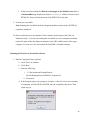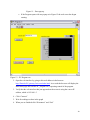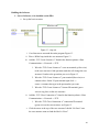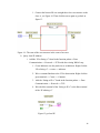
1
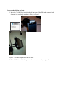
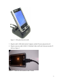
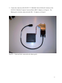
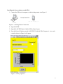
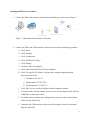
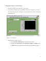
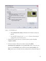
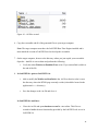
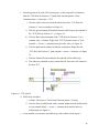
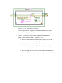
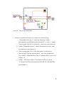
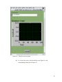
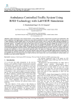
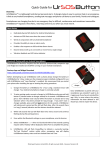
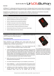
PDA Data Acquisition and Control System
User Manual
Patrick Bowles & Scott Marks
CDA 4170 – Data Acquisition and Control Systems
Janusz Zalewski, Ph.D.
Florida Gulf Coast University
April 23, 2009
Hardware Installation and Setup
1. Insert the CF-6004 Data Acquisition board into to top of the PDA in the compact flash
slot until it is completely seated in the PDA, see Figure 1.
Figure 1 – CF-6004 being inserted into the PDA
2. Place the PDA into the docking station referred to as the cradle, see Figure 2.
2
Figure 2 – PDA placed into the cradle
3. Plug the cradle’s USB cable into the Computer, and the DC power plug in the wall.
4. Plug the connector cable NI SH-15-15 Shielded Cable with D-sub Connector into the CF6004, see Figure 3.
Figure 3 – Connector cable installed in the CF-6004.
3
5. Connect the connector cable NI SH-15-15 Shielded Cable with D-sub Connector to the
NI SCB-15 Shielded Compact Connector Block (DB-15 adapter), see Figure 4. The
Battery pack is already connected to the DB – 15 adapters, see Figure 4.
Figure 4 – Connector block connected to the battery pack.
4
Installing the Server software on the PDA
1. Connect the PDA to the computer via the docking station as in Figure 5:
Figure 5 – Docking Station Connection
2. Open LabVIEW
3. Open the LabVIEW Project Labeled: PDA_Project.lvproj
4. From the Project Window open the LabVIEW VI Labeled: PDA_Program.vi. As a result
a window shown in Figure 6 will appear.
Figure 6 – PDA_Program.vi
5
5. Click the run button
on the toolbar of the VI, and wait for LabVIEW to finish
uploading the software to the PDA it will take approximately 3 minutes. If the VI does
not load after that a possible error may have occuried.
a. Possible Solutions
i. Verify that the cradle’s USB cable is connected to the development
computer.
ii. Verify that the PDA_Program.vi is not already loaded into the PDA
memory using the following steps.
1. On the PDA, click “Start”
2. Click “Settings”
3. Click on the “System” Tab
4. Click “Memory”
5. Click on the “Running Programs” Tab if the program is in the list
select it then click “Stop”
6. Click “Ok” & “Exit”
iii. If the first two solutions don’t help completely shut down LabVIEW and
restart it.
6. Remove the PDA from the docking station (optional).
6
Running the PDA Server Software
1. Connect the PDA to the compact connector block and battery pack as seen in Figure 7:
Figure 7 – Illustration of the Physical Connection.
2. Connect the PDA to the CSPrivateLab wireless network using the following procedure:
a. Click “Start”
b. Click “Settings”
c. Click “Connections”
d. Click “Dell WLAN Utility”
e. Click “Setting”
f. Click tab “Network Adapters”
g. Click “Dell Axim X50 WLAN Wireless Adapter”
h. Click “Use specific IP Address” and type these settings:(depending on the
network you run it on)
i. IP address: 192.168.1.5
ii. Subnet mask: 255.255.255.0
iii. Default gateway: 192.168.1.1
i. Click “OK” twice to exit the Configure Network Adapters settings.
j. If wireless card is already enabled, press twice the wireless button on the left side
of the PDA, to disconnect it first.
k. To enable wireless with the new configureation, press twice the wireless button
on the left side of the PDA
l. Connect to the CSPrivateLab wireless network using the correct key (obtained
from Dr. Zalewski)
7
3. Run the PDA(Server) software:
a. Click “Start”
b. Click “File Explorer”
c. Click “PDA”
8
Setting up the Web Server Client Software
1. Open the LabVIEW Project Labeled: PC_Project.lvproj.
2. From the Project Window open the LabVIEW VI Labeled: PC_Program.vi. As a result
the window shown in Figure 8 will appear. The development of the Client VI is described
in the build section.
Figure 8 – PC_Program.vi
3. Build the html web page for your VI:
•
Select Tools»Web Publishing Tool... from the Project explorer
•
Configure the Viewing Mode as either Embedded, Snapshot, or Monitor (click
the Help button for an explanation of each option) and click Next as in Figure 9.
9
Figure 9 – Web Publishing tool
•
Edit the Document title, Header, and Footer and click Next to configure the
html file.
•
Save the HTML document in your \labVIEW\www directory while noting the
resulting URL (you will need it for step 9)
4. Add the HTML document from step 3 to Project Explorer by right-clicking My
Computer»Add»File
5. In the Project Explorer, Build your executable by right-clicking Build
Specifications»New»Application. Select the Source Files category. Then, place your
top level VI under Startup VIs and your HTML file under Always Included. Click
Build, which creates an executable and some configuration file as illustrated in figure 10.
10
Figure 10 – All files created
6. Copy the executable and all of the generated files to your target computer
Note: The target computer must have the LabVIEW Run-Time Engine installed and it
must match the version of LabVIEW used to develop the executable.
7. On the target computer, browse to the directory where you just copied your executable.
Open the .ini file in a text editor and perform the following:
•
Verify the token WebServer.Enabled=True exists. If you cannot find it, add it to
the end of the file
8. In LabVIEW 8.x prior to LabVIEW 8.6:
•
Add or modify the WebServer.RootPath in the .ini file so that its value is set to
the directory where the HTML page currently resides (it should be located in the
application's data directory)
•
Save the changes to the .ini file and close it
In LabVIEW 8.6 and later:
•
Close the .ini file and open niwebserver.conf in a text editor. This file was
created to handle the new functionality provided by the LabVIEW web server in
LabVIEW 8.6
11
•
In the second section labeled Directives that apply to the default server there is
a DocumentRoot tag. Replace the default LabVIEW\www with the location of your
HTML file. Do not include the name of the HTML file in the path
9. Launch your executable
Note: Running the executable on the development machine requires that LabVIEW be
completely shutdown.
10. Open a web browser on any Internet Client computer and navigate to the URL you
obtained in step 3. If you are not running the executable on your development machine,
replace the name of the development computer in the URL with the name of the target
computer. You can now view and control the LabVIEW executable remotely.
Running the Web Server Executable Software
1. Run the Computer(Client) software:
a. Click “Start” in windows.
b. Click “Run”
c. Enter the following:
i.
“C:\Documents and Settings\Patrick
Bowles\Desktop\Project\builds\PC_Program.exe”
ii. Press enter
d. If the Program opens with a popup as in Figure 11 the web server is not running
exit program, and LabVIEW. LabVIEW must be completely shut down. Then
repeat step (a).
12
Figure 11 – Error pop-up
e. If the Program opens with out popup as in Figure 12 the web server has began
running.
Figure 12 – PC Program.exe
2. Open the web interface by going to this web address in the browser:
http://Patricks-PC.gateway.2wire.net/index.html. As a result the browser will display the
index.html page and load the PC_Program.exe, requesting control of the program.
3. Verify that the web interface that just appeared on the screen is using the correct IP
address, which is 192.168.1.5
4. Click “Connect”
5. Wait for readings to show in the graph
6. When you are finished click “Disconnect” and “Exit”
13
Building the Software
1. Server Software, to be installed on the PDA
a. Set up the basic structure
Figure 13 - step one.
i. Case Structure to surround the entire program Figure 13.
ii. Place a While loop inside the case structure Figure 13.
iii. Add the “TCP Create Listener.vi” found in the function palette>>Data
Communication >> Protocols >>TCP.
1. Wire the “TCP Create Listener.vi” error out terminal (yellow wire)
to the case structure’s little question mark this will change the case
structure’s border to the green that you see in Figure 13.
2. Wire the “TCP Create Listener.vi” port terminal (blue wire) to a
constant value. On the VI port terminal right click >>
create>>constant, then type in the port number you want.
3. Wire the “TCP Create Listener.vi” listener ID terminal (green
wire) to any place on the case structure.
iv. Add the “TCP Close Connection.vi” found in the function palette>>Data
Communication >> Protocols >>TCP.
1. Wire the “TCP Close Connection.vi” connection ID terminal
(green wire) to the case structure, see Figure 13.
v. Click the arrow at the top of the case structure Labeled “No Error” once
the case structure turns red and the label is “Error”
14
1. Connect the listener ID wire straight threw the case structure to the
close vi, see Figure 14. Then click the arrow again to get back to
figure 13.
Figure 14 - The state of the case structure in the event of an error.
b. Query local IP Address
i. Add the “IP to String.vi” found in the function palette>>Data
Communication >> Protocols >>TCP inside the existing While Loop.
1. Create Indicator wire the pink wire to an Indicator. Right click the
“IP to String.vi” >>create >> indicator.
2. Wire a constant Boolean to the VI for dot notation. Right click the
green terminal >> Create >> Constant.
3.
Add the “String to IP.vi” found in the function palette >> Data
Communication >> Protocols >>TCP.
4. Wire the blue terminal of the “String to IP.vi” to the blue terminal
of the “IP toString.vi”
Figure 15 get local IP.
15
c. From this point on all code will be inside part a. while loop and Case Structure.
Add the “TCP Wait On Listener.vi” found in the function palette>>Data
Communication >> Protocols >>TCP.
i. Wire the yellow error wire from the while loop to the “TCP Wait On
Listener.vi” error in terminal, see figure 16.
ii. Wire the green listening ID terminal from the while loop to the terminal of
the “TCP Wait On Listener.vi” , see figure 16.
iii. Wire the blue timeout terminal of the “TCP Wait On Listener.vi” to a
constant value = 3000ms. Right click “TCP Wait On Listener.vi” blue
terminal >> Create >> constant, then type in the value, see figure 16.
iv. Wire the pink remote address terminal to an indicator. Right click the
“TCP Wait On Listener.vi” pink terminal >>create >> indicator, see figure
16.
v. Wire the listener ID out terminal to the right side of the while loop.
vi. The other two terminals to deal, (connection ID, Error out) will connect to
the next TCP
Figure 16 – TCP wait VI
d. While loop wait timer.
i. Add the “Wait (ms).vi” found in the function palette>>Timing.
ii. Wire the delay in millisecond with a constant. Right click the milliseconds
to wait terminal (blue) >> create >> constant, then enter the delay in
milliseconds, see figure 16.
e. Create another case structure and while loop comb similar to that in part a.
16
Figure 17 – Case, while and TCP write.vi
i. Will not repeat how to setup the Case structure and while loop again,
please refer to the beginning of this section.
ii. Add the “TCP Write.vi” in the while loop, found in the function
palette>>Data Communication >> Protocols >>TCP.
1. Wire the connection ID (green) and error (yellow) wires to and
from the write VI as seen in figure 17.
2. Add the “Unbundle by Name.vi” and connect the error wire to the
input side of the Unbundle VI, and the output side to a “logical or”
connector then to the loop terminator.
3. Wire the string data (Pink) to the Write VI, this is the data that is
collected by the data acquisition part of this project, see figure 17.
17
Figure 18 – Source code for the DAQ.
f. The data Acquisition subVI has to be created in the following steps:
i.
“DAQmxBase Start task.vi”, outside the while loop, with the
task/channels in wired. Right click the Start task VI >> create >> control.
ii. Wire the purple Task out wire and yellow – error wires to the while loop.
iii. Add the “DAQmxBase Read.vi” connect the terminal wire to the while
loop junction as seen in figure 18.
iv. Wire the orange data wire to a Waveform graph VI on the project.
v. After the purple Task out wire and yellow – error wires exit the while
loop, Add the “DAQmxBase Stop Task.vi” and attach the to wires as seen
in figure 18.
vi. Add the “”PDA error handler.vi” found in the vi.lib file, located at
“C:\Program Files\National Instruments\LabVIEW 8.2\vi.lib\PDA\PDA
Error Handler.vi”.
18
Figure 19 – DAQ for retrieving data.
vii. As a result, the source code should look as in Figure18, with
corresponding front panel in Figure 19.
19
Client Software, to be installed on computer to host webpage.
Figure 20 – Client Software
g. Set up the basic structure
i. Case Structure to surround the entire program Figure 20.
ii. Place a While loop inside the case structure Figure 20.
iii. Add the “TCP Open Connection.vi” found in the function palette>>Data
Communication >> Protocols >>TCP.
1. Wire the “TCP Open Connection.vi” error out terminal (yellow
wire) to the case structure’s little question mark this will change
the case structure’s border to the green that you see in Figure 20.
2. Wire the “TCP Open Connection.vi” port terminal (blue wire) to a
constant value. On the VI port terminal right click >>
create>>constant, then type in the port number you want.
3. Wire the “TCP Open Connection.vi” connection ID terminal
(green wire) to any place on the case structure.
4. Wire the pink address terminal to a control. On the VI address
terminal (pink)right click >> Create >> Control.
iv. Add the “TCP Close Connection.vi” found in the function palette>>Data
Communication >> Protocols >>TCP.
1. Wire the “TCP Close Connection.vi” connection ID terminal
(green wire) to the case structure, see Figure 20.
v. Click the arrow at the top of the case structure Labeled “No Error” once
the case structure turns red and the label is “Error”
20
1. Connect the connection ID wire straight threw the case structure to
the close VI, see Figure 14. Then click the arrow again to get back
to figure 20.
h. Inside the While loop.
i. Add the “TCP Read.vi” twice, as seen in figure 20.
21