1
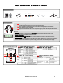
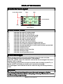
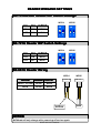
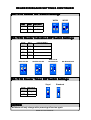
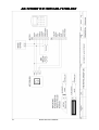
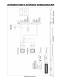
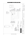
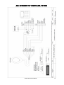
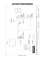
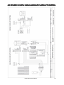
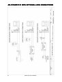
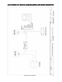
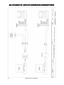
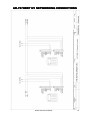
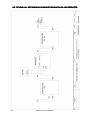
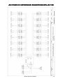
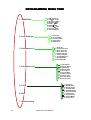
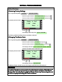
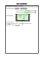
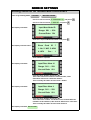
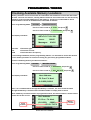
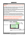
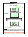
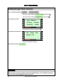
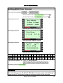
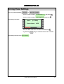
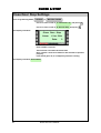
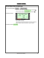
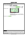
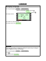
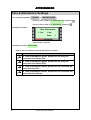
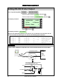
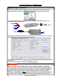
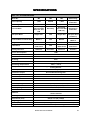
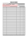
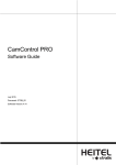
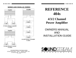
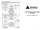
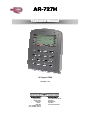
ARAR-727H Technical Manual 26 August 2008 Version 1.10 Southern Office: Raytel House Brook Road Rayleigh Essex, SS6 7XH Tel: (01268) 749310 Fax: (01268) 749315 Northern Office: 20-23 Woodside Place, Glasgow, Strathclyde, G3 7QF. Tel:(0141) 5821275 CONTENTS GENERAL INFORMATION System Overview ..................................................................................... 4 Box Contents, Installation & Connectors .................................................. 5 Display and Keypad Layout ...................................................................... 6 Display Messages..................................................................................... 7 Reader Wiegand Settings ......................................................................... 8 Wiring Diagrams..................................................................................... 10 Programming Menu Tree ........................................................................ 22 PROGRAMMING Initial Setup ............................................................................................ 23 Changing Control Mode.......................................................................... 24 System Information & Clock Settings ..................................................... 26 Lock Time & Latch Mode ........................................................................ 27 Setting Exit Button Function ................................................................... 28 Setting Node ID For Networked Controllers ........................................... 29 Checking Available Memory Locations ................................................... 30 Add Card ID............................................................................................ 31 Add RF-Learn To Enter Sequential Tokens ............................................. 33 Add RF-Learn To Enter Non Sequential Tokens ...................................... 34 Add RF-Learn To Enter A Single Token................................................... 35 Setting Access Mode For Tokens ........................................................... 36 Suspend Address ................................................................................... 37 Recover Address ................................................................................... 38 Delete Address....................................................................................... 39 Suspend ID............................................................................................. 40 Recover ID ............................................................................................. 41 Delete ID ................................................................................................ 42 Setting Anti-passback ............................................................................ 43 Setting Anti-passback For Individual Addresses .................................... 44 Setting Anti-passback For Multiple Addresses ....................................... 45 Auto Open Zone Settings........................................................................ 46 Open Time Zone Settings ....................................................................... 47 2 RSSD AR-727H MANUAL CONTENTS CONTINUED Lift Control Setting Single Floor Access ................................................. 48 Lift Control Setting Multi Floor Access ................................................... 49 Setting AR-401RO16B DIP Switches....................................................... 50 Doorbell Settings.................................................................................... 51 Auto Relock Settings .............................................................................. 52 Door Close Time Settings ....................................................................... 53 Alarm Relay Time Settings ..................................................................... 54 Alarm Delay Time Settings ..................................................................... 55 Arming Password Settings ..................................................................... 56 Arming Pulse Settings ............................................................................ 57 Close Door Stop Settings ....................................................................... 58 Force Open Alarm Settings .................................................................... 59 Duress Code Settings............................................................................. 60 Changing Language ............................................................................... 61 Time & Attendance Settings ................................................................... 62 Setting Serial Port Output ...................................................................... 63 Setting RS232 Printer Output ................................................................. 64 Resetting Master Code ........................................................................... 65 Upgrading Firmware .............................................................................. 66 Specifications ........................................................................................ 67 Table Of Users ....................................................................................... 68 RSSD AR-727H MANUAL 3 SYSTEM OVERVIEW The ARAR-727H Controller The AR-727H is a versatile single door proximity controller that can be used as stand-alone or networked. Key Features: 4 Built-in Proximity reader 1,024 User card capacity, 65,536 User card capacity in stand-alone mode Tamper Switch 32 floor lift control Door Monitoring Code in/Code out (with additional Wiegand Keypad) Optional Anti-pass back function with Code In/Out Optional Egress Function Network capability up to 254 x 16 doors each with Keypad In/Out Programmable Duress Code Optional Lock Output - Timed 0.1 to 600 seconds, Latched On/Latched Off Universal Serial Port for LED Display, Printer, Lift Control etc. Alarm function for Tamper, Forced Entry, Duress and Door Open Will run as a Standalone Controller during Host Controller failure Add tokens/cards using built in reader Buffer for storing up to 1,200 Transactions Auto-Relock Function Real Time Clock 2x Auto Open Time Zones in Standalone mode with Firmware version 7V4 and earlier 10x Auto Open Time Zones in Standalone mode with Firmware version 7V5 and later IP65 rated RSSD AR-727H MANUAL BOX CONTENTS & INSTALLATION BOX CONTENTS C. Connection Cables C.Terminal Cable B.B.User User Guide Guide A. Controller A.Reader INSTALLATION STEPS 2 D. Water Resistant Strip D.Water-risisting Strip E. Allen Key Screws E.Screw && Wrench 1 Screw mounting plate to the wall. 2 Pull cable ends through the access hole in the mounting plate. 3 Attach controller to the mounting plate and install screw (supplied) into the hole at the bottom with the allen key (supplied). 1 3 4 Apply power. Sounder will emit a short beep and the green power LED & display will illuminate. NOTICE 4 CONDUIT The communication wires and power line Should Not be housed in the same electrical conduit. They should always be installed in separate conduit. CABLE SELECTION Use twisted pair and Do Not star out. This will cause problems with data to and from the readers. POWER SUPPLY Do Not connect the reader and lock to the same power supply. While the lock is active it can destabilize the power supply and effect the readers function. The standard connection of the power supply is to connect the door relay and lock to one power supply and the reader on a separate power supply. CONNECTOR DIAGRAM P1 Table1: CN-3 Colour Coding Wire Application Door Relay 2 Description Colour Blue/White NO 24VDC 1A Purple/White NC 24VDC 1A Door/Alarm Relay 3 Door Sensor 4 Exit Switch 5 6 White Orange Purple Grey 7 Thick Red DC Power 12V 8 Thick Black DC Power 0V Alarm Relay Power P2 Wire 1 P3 Table3: CN-4 Colour Coding Wire Application Wire 1 Colour 2 Orange Yellow Tamper Switch Red 3 COM 24VDC 1A Negative Trigger Input Description Normally Closed Common Normally Open Negative Trigger Input NO/NC Optional (By Jumper) P1 P2 P3 Table2: CN-1 Colour Coding Wire Application Networking P4 Wire Colour 1 2 Thick Green Thick Blue 3 Thin Blue Wiegand Buzzer LED Description RS-485 (B-) RS-485 (A+) Wiegand DAT:1 Input BA Clock Input (W1) P4 Table4: CN-2 Colour Coding Wire Application Arming Setting Input Wire 1 Colour Serial Port 2 Yellow/White Wiegand DAT:0 Input BA Data Input (W0) Arming Status Output 3 Red/White Buzzer Output 5V 100mA, Low Green LED Output 5V 20mA, Max Card Present 4 Brown/White . 4 Thin Green 5 6 Pink 7 Brown Yellow Description Orange/White on off Arming Output (Active Low) Card Present Output Active Low (Transistor Output) Red LED Output 5V 20mA, Max RSSD AR-727H MANUAL Latch Type Serial Output (Transistor Open Collector) (4800,N,8,1) 5 DISPLAY AND KEYPAD LAYOUT LAYOUT Front Panel Layout Work Status Day Date Arming (Green) Alarm (Red) Receive (Red) Transmit (Green) 18/02 FRI Duty:0 10 : 49 : 34 Ready….. Input Indicator (Red) Card Present (Green) Stand-by (Green) Error (Red) Up Down Left Escape/Quit Right Enter/OK LED’s Arming (Green) Alarm (Red) Receive (Red) Transmit (Green) Input Indicator (Red) Card Present (Green) StandStand-by (Green) Error (Red) - Indicates Arming function is active. Indicates Alarm function is active. Indicates data received from host. Indicates data transmitted to host. Indicates peripheral device to activate arming status is active. - Indicates a card is present at the reader. - Indicates power on/operating OK. - Indicates system error. Display Date Day Work Status - Shows current date. - Shows current day of the week. - Shows current Work Status. Buttons F1 F2 F3 F4 # &# 6 - Navigates up the menu. In Time & Attendance mode, press once for Duty On, press twice for Break Start. - Navigates down the menu. In Time & Attendance mode, press once for Duty Off, press twice for Break End. - Navigates up the menu. In Time & Attendance mode, press once for Overtime On, press twice for Go. - Navigates down the menu. In Time & Attendance mode, press once for Overtime Off, press twice for Return. - Press to escape current menu screen. - Press to enter data. - Press together to lock/unlock Keypad. RSSD AR-727H MANUAL DISPLAY MESSAGES Events Screen Layout Event Status Code Date Time A 10/18 16:42:32 FRI 00153 1200 16 05/13 12:09:55 WED 00001 0001 Event Number Day User Address Event Status Code A: B: C: D: E: F: G: H: 01: 03: 04: 11: 16: 17: 31: Indicates the start of a duty period Indicates the end of a duty period Indicates the start of an overtime period Indicates the end of an overtime period Indicates the start of a break period Indicates the end of a break period Indicates user has left the premises Indicates the user has returned to the premises Indicates an erroneous password has been entered Indicates an unprogrammed or invalid card has been presented Indicates a time-zone error Indicates normal access Indicates egress via exit function Indicates an alarm state Indicates an anti-passback error Event Messages When viewing events, the screen will always show 2 events at a time. The controller can store a maximum of 1,200 events. After the 1,200th event, the controller overwrites the messages from event number 0001 onwards. Two messages are shown on screen at a time and scrolling up (with F1) or down (with F2) will take you to the next or previous message. The messages can be deleted from the controller by performing a factory reset. NOTICE If a Factory Reset is performed to erase the event messages, all other programming will be lost. Before attempting a Factory Reset make a record of all necessary programming. RSSD AR-727H MANUAL 7 READER WIEGAND SETTINGS SETTINGS ARAR-737HB737HB-RAY Reader DIP Switch Settings WG34 SW1 SW2 OUTPUT ON OFF WG34 OFF OFF WG26 WG26 ON 1 ON 2 1 2 ARAR-721U Reader DIP Switch Settings WG34 SW1 SW2 OUTPUT OFF ON WG34 OFF OFF WG26 WG26 ON 1 ON 2 1 2 ARAR-661U Reader Wiring YELLOW BROWN OUTPUT SHORT TO GND OPEN WG34 OPEN OPEN WG26 WG34 WG26 AR-661U AR-661U SHORT TO GROUND NOTICE WG Mode will only change after powering off and on again. 8 RSSD AR-727H MANUAL OPEN READER WIEGAND SETTINGS SETTINGS CONTINUED ARAR-737U Reader DIP Switch Settings WG26 WG34 SW1 SW2 OUTPUT OFF OFF WG34 ON OFF WG26 ON 1 ON 2 1 2 ARAR-737U Reader Indication DIP Switch Settings SW3 SW4 INDICATION ON ON Red LED On OFF ON Green LED On ON OFF Red LED & Buzzer On OFF OFF No Indication RED LED ON ON 3 RED LED & BUZZER ON GREEN LED ON ON ON 4 3 NO INDICATION 3 4 ON 4 3 4 ARAR-737U Reader Token DIP Switch Settings Soyal SW5 TOKENS ON Soyal OFF Standard Standard ON ON 5 5 NOTICE WG Mode will only change after powering off and on again. RSSD AR-727H MANUAL 9 ARAR-727HBR1121 WITH ARAR-737HB737HB-RAY 10 RSSD AR-727H MANUAL ARAR-727HBR1121 WITH 2X 2X ARAR-737HB737HB-RAY FOR READ ININ-READ OUT RSSD AR-727H MANUAL 11 ARAR-727HBR1121 WITH ARAR-721U 12 RSSD AR-727H MANUAL ARAR-727HBR1121 WITH ARAR-727HU RSSD AR-727H MANUAL 13 ARAR-727HBR1121 WITH ARAR-661U 14 RSSD AR-727H MANUAL ARAR-727HBR1121 WITH SINGLE SINGLE AND MULTI FLOOR LIFT CONTROL RSSD AR-727H MANUAL 15 ARAR-727HBR1121 WITH OPTIONAL OPTIONAL LOCK CONNECTIONS 16 RSSD AR-727H MANUAL ARAR-727HBR1121 WITH ALARM ALARM SOUNDER AND DOOR CONTACTS RSSD AR-727H MANUAL 17 ARAR-727HBR1121 WITH PC INTERFACE CONNECTIONS CONNECTIONS 18 RSSD AR-727H MANUAL ARAR-727HBR1121 NETWORKING NETWORKING CONNECTIONS RSSD AR-727H MANUAL 19 ARAR-727HBR1121 NETWORKING NETWORKING CONNECTIONS WITH RSRS-485 REPEATER 20 RSSD AR-727H MANUAL ARAR-727HBR1121 NETWORKING NETWORKING CONNECTIONS WITH ARAR-716E RSSD AR-727H MANUAL 21 PROGRAMMING MENU TREE 1. Add/Delete 2. User Settings 1. Add Card ID 2. Add RF Learn 3. Suspend Addr 4. Suspend ID# 5. Delete Addr 6. Delete ID# 7. Recover Addr 8. Recover ID# 9. Antipass Group 1. Password 2. Access Mode 3. Extend Options 4. Single Floor 5. Multi Floors 1. Node ID 2. Auto Open Zone 3. Door Relay Tm 4. Door Close Tm 5. Alarm RelayTm 6. Alarm DelayTm 7. ArmingDelayTm 8. Arming PWD. 9. Arming Pulse 3. Parameters (1) 1. Auto Relock 2. Egress (R.T.E) 3. Attendance 4. Master Node 5. Force Open.. 6. Close & Stop 7. Anti-passback 8. Duress Code 9. Factory Reset 0. Key (#) is Bell 4. Parameters (2) 1. Language 2. Master Code 3. Master Range 4. Terminal Port 5. AR401R16 Port 6. Open TimeZone 7. Informations 8. Clock Setting 9. Control Mode 0. View Events 5. Tools 6. Quit 7. Quit & Arming 22 RSSD AR-727H MANUAL INITIAL PROGRAMMING Initial Setup 1. Restoring Factory Settings Enter Programming Mode *123456# or *MASTER CODE# Use F1 or F2 to scroll to 4.PARAMETERS (2) and press # Use F1 or F2 to scroll to 9.FACTORY RESET and press # The display will now show:- Ready to 1: YES Go? 2:NO Data: 1 Press 1 or # The display will briefly show INITIAL SYSTEM… The factory default settings have now been restored. 2. Changing The Master Code Enter Programming Mode *123456# or *MASTER CODE# Use F1 or F2 to scroll to 5.TOOLS and press # Use F1 or F2 to scroll to 2.MASTER CODE and press # The display will show INPUT 6 DIGIT NO 000001~999999 ENTER THE NEW 6 DIGIT MASTER CODE. The display will now show:- Ready to 1: YES Go? 2:NO Data: 1 Press 1 or # The display will show SUCCEEDED! The Master Code should now be the 6 digit code that was just entered. NOTICE It is important that a record of the new Master Code is kept somewhere safe in case any further programming is required. Once changed, if the Master Code is lost, the only way to reset the Master Code is by connecting the unit to a PC or Laptop and using ISP Tools software. RSSD AR-727H MANUAL 23 CONTROL MODE Changing Control Mode AR-727H MODE 4 MODE 6 MODE 8 NETWORKING 1,024 65,536 1,024 Depends on Controller § Card Only Card and PIN User No and PIN Card Only Card Only Card and PIN PIN only Card Only Card and PIN User No and PIN PIN only Anti-Pass Back Single Door N/A Single Door Up To 16 Doors Code Capacity 1,024 1 1,024 Depends on Controller † Event Capacity 1,200 N/A 1,200 Depends on Controller ‡ 4 Digit Code N/A 4 Digit Code Up To 4x 4 Digit N/A N/A N/A 11 Time Zones Control Mode in Networking Mode 4 N/A Mode 8 Mode 4 or Mode 8 Wiegand Output WG32 WG16 WG32 WG32 32 Floors 1,024 Card Users N/A User Card Capacity Access Mode Duress Time Zone Lift Control 32 Floors 32 Floors 1,024 Card Users 1,024 Card Users § If using an AR-716E, User Card Capacity can be up to 15,000 Users. † If using an AR-716E, Code Capacity can be up to 15,000 codes. ‡ If using an AR-716E, Event Capacity can be up to 11,000 events. Control Modes Mode 4 is for Stand-Alone and Networking directly to a PC or under a 716E. This is similar to Mode 8 with the only difference being in Access Mode. Mode 6 is for Stand-Alone applications only. Mode 8 is for Stand-Alone and Networking directly to a PC or under a 716E. This is similar to Mode 4 with the only difference being in Access Mode. Networking is for Modes 4 and 8 and is specifically for networking either directly to a PC or under a 716E. NOTICE When changing Control Mode from Mode 6 to Mode 4 and vice versa, it is necessary to delete all User Card Data first. 24 RSSD AR-727H MANUAL CONTROL MODE Changing Control Mode Continued Enter Programming Mode *123456# or *MASTER CODE# Use F1 or F2 to scroll to 5. Tools and press # Use F1 or F2 to scroll to 9. Control Mode and press # The Display will show:- 1: M4 2:M6 3:M8 Current Data: 1 4:M9 Enter number for required Control Mode. The Display will show:- Egress Sounds : 1:B . . BB 3:No 2:B . . Curr. : 1 Enter number for required Egress Tone. Parameter Function 1:B..BB Triple Beep 2:B.. Single Beep 3:No No Beep The Display will show:- Tags Format 1:Normal 2:SOYAL Data: 1 Enter Number for required Tag Format. The Display will now show Succeeded ! NOTICE When changing Control Mode from Mode 6 to Mode 4 and vice versa, it is necessary to delete all User Card Data first. RSSD AR-727H MANUAL 25 SYSTEM INFORMATION & CLOCK SETTINGS Viewing Information Enter Programming Mode *123456# or *MASTER CODE# Use F1 or F2 to scroll to 5. Tools and press # Use F1 or F2 to scroll to 7. Informations and press # The Display will show:- AR7x7V3 7V3.125K Users: 00025 Messages: AR7x7V3 7V3. 125K Users: 00025 Messages: 00456 00456 = The version of Firmware and Frequency. = The quantity of tokens programmed. = The quantity of stored messages. Setting Clock Enter Programming Mode *123456# or *MASTER CODE# Use F1 or F2 to scroll to 5. Tools and press # Use F1 or F2 to scroll to 8. Clock Setting and press # The Display will show:- Input Date & Time YyMmDdHhMmSs Enter the time and date The Display will show:- Month/Day Format 1: DD/MM 2: MM/DD Current Data: 2 Enter the required number for month/day format and press # The Display will now show Succeeded ! 26 RSSD AR-727H MANUAL LOCK TIME AND LATCH MODE Setting Lock Time Enter Programming Mode *123456# or *MASTER CODE# Use F1 or F2 to scroll to 3. Parameters (1) and press # Use F1 or F2 to scroll to 3. Door Relay Tm and press # Input: The Display will show:- 0 ~ 600 Current Data: 002 Enter the time required in seconds and then press # E.g. Entering 010 will give a lock open time of 10 seconds. The Display will now show Succeeded ! Setting Latch Mode Enter Programming Mode *123456# or *MASTER CODE# Use F1 or F2 to scroll to 3. Parameters (1) and press # Use F1 or F2 to scroll to 3. Door Relay Tm and press # The Display will show:- Input: 0 ~ 600 Current Data: 002 Enter 0 and # press The Display will now show Succeeded ! NOTICE When Latch Mode has been set, the lock relay will switch and the door will latch open after a valid programmed token has been presented. The door will then stay open until a valid programmed token is presented and then the relay will switch back and the door will lock. RSSD AR-727H MANUAL 27 EXIT FUNCTION Setting Exit Button Function Enter Programming Mode *123456# or *MASTER CODE# Use F1 or F2 to scroll to 4. Parameters (2) and press # Use F1 or F2 to scroll to 2. Egress (R.T.E) and press # The Display will show:- Request To Exit 1: YES 2:NO Data: 1 Enter number required. Entering 1 will enable Exit function, entering 2 will disable Exit Function. The Display will now show Succeeded ! 28 RSSD AR-727H MANUAL NODE ID SETTINGS Setting Node ID for Networked Controllers Enter Programming Mode *123456# or *MASTER CODE# Use F1 or F2 to scroll to 3. Parameters (1) and press # Use F1 or F2 to scroll to 1. Node ID and press # Input New Node ID The Display will show:- Range: 001 ~ 254 Current Data: 001 Enter the required Node ID number and press # Show Card The Display will now show:- ID ? 1: No 2: WG 3: ABA 4: HEX Cur. : 1 Enter Number required. Input Door Num: H The Display will show:- Range: 001 ~ 254 Current Data: 001 Input the Door Number and press # This is the Hardware number of the Controller, each Controller must have a different number. This is usually the same as Door Num: L below. Input Door Num: L The Display will show:- Range: 001 ~ 254 Current Data: 001 Input the Door Number and press # This is the Door number. For all the doors to show different numbers in the software, this must be different for each door. This is usually the same as Door Num: H above. The Display will show Succeeded! RSSD AR-727H MANUAL 29 PROGRAMMING TOKENS Checking Available Memory Locations Memory locations can be overwritten on controllers with Firmware version 7V4 and earlier (on later versions of firmware, existing tokens cannot be overwritten but it is still necessary to keep a record of token addresses in the memory), therefore it is advisable to check which firmware version is installed on the controller as follows:Enter Programming Mode *123456# or *MASTER CODE# Use F1 or F2 to scroll to 5. Tools and press # Use F1 or F2 to scroll to 7. Informations and press # The Display will show:- AR7x7V3 7V3.125K Users: Messages: AR7x7V3 7V3. 125K 00025 00456 = Controller type. = Firmware Version. = The Controllers Frequency. In an existing installation, before programming tokens, it is advisable to check the amount of free memory locations to avoid overwriting any previously programmed tokens. View the remaining memory locations as follows:Enter Programming Mode *123456# or *MASTER CODE# Use F1 or F2 to scroll to 1. Add/Delete and press # Use F1 or F2 to scroll to 1. Add The Display will show:- Card ID and press # User Address : F3: Prev F4: Next (0-01023):00000 Use F1 to scroll backwards through the Memory Locations, use F2 to scroll forwards through the Memory Locations until a suitable number of empty slots is found. When a Memory Location contains a programmed token, the token number is shown on the bottom line of the screen:- User Address : F3: Prev F4: Next Token Number 30 (0-01023): 00000 05121:73478 RSSD AR-727H MANUAL Memory Location ADD/DELETE WARNING Before Proceeding with any token programming, please read the following. The last page of this manual is a token/memory slot record sheet. The blank sheet should be photocopied and the photocopy kept up-to-date with the location and number of each token added or deleted. Failure to do so might result in valid tokens being overwritten when batches of tokens are added en bloc, if deletion of individual tokens have left vacant memory slots scattered amongst valid tokens. If the first token in a new batch is directed to a single vacant memory slot, then the rest of the batch will overwrite (and replace) any subsequent valid tokens in the memory. For this reason, it is advisable to read the section “Checking Available Memory Locations” (page 38 opposite) before adding tokens since the F3 and F4 functions can be used to identify the location and quantity of vacant memory slots even if the Token Record Sheet has not been kept up-to-date. This applies to all firmware versions up to and including 7V4. Version 7V5 automatically avoids overwriting valid tokens. A record should still be kept of token location in the memory, however, to facilitate deletion of specific tokens. Add Card ID Enter Programming Mode *123456# or *MASTER CODE# Use F1 or F2 to scroll to 1. Add/Delete and press # Use F1 or F2 to scroll to 1. Add The Display will show:- Card ID and press # User Address : F3: Prev F4: Next (0-01023):00000 Enter the User Address, for this example 00000 and press # (User Address is the memory slot into which the token will be entered) Continued Over RSSD AR-727H MANUAL 31 ADD/DELETE Add Card ID continued. The Display will now show:- Set 00000 Site: 00000:00000 (1-65535) 00001 Enter the FIRST five digit number on the bottom line of the token Using this token as an example, type in 00012 The Display will now show:- Set 00000 Code: 00012:_xxxx (1-65535) 00001 Enter the SECOND five digit number on the bottom line of the token Using the above example, type in 62362 The Display will briefly show:- Set ***** Code: 00012:62362 Scan Data: XXXX **** Scan Data: XXXX will quickly scroll through 00001 to 65535 The Display will now show:- Completed! Address: 00000 ID: 00012:62362 The Token has been programmed successfully. 32 RSSD AR-727H MANUAL ADD/DELETE Add RF-Learn To Enter Sequential Tokens Enter Programming Mode *123456# or *MASTER CODE# Use F1 or F2 to scroll to 1. Add/Delete and press # Use F1 or F2 to scroll to 2. Add The Display will show:- RF-Learn and press # User Address : F3: Prev F4: Next (0-01023):00000 Enter the User Address, for this example 00001 and press # (User Address is the memory slot into which the first token of the batch will be entered) The Display will now show:- Tag Units (pcs) Must Be Sequence (1-01024): 00001 Enter the quantity of tokens to be programmed, for this example 10 and press # The Display will now show:- Close Tag Into RF Area Present the token with the lowest Card Code number to the bottom of the controller. The Display will now show:- Close Tag Into RF Area 00001 - 00010 OK ! All Tokens have been successfully programmed. RSSD AR-727H MANUAL 33 ADD/DELETE Add RF-Learn To Enter Non Sequential Tokens Enter Programming Mode *123456# or *MASTER CODE# Use F1 or F2 to scroll to 1. Add/Delete and press # Use F1 or F2 to scroll to 2. Add The Display will show:- RF-Learn and press # User Address : F3: Prev F4: Next (0-01023):00000 Enter the User Address, for this example 00001 and press # (User Address is the memory slot into which the first token of the batch will be entered) The Display will now show:- Tag Units (pcs) Must Be Sequence (1-01024): 00001 Press 1 and # together. The Display will now show:- Close Tag Into RF Area Present the first token to the bottom of the controller. The Display will now show:- Close Tag Into RF Area 00001 - 00001 OK ! Present the rest of the tokens one at a time, and when finished press until the display shows 6. Quit and then press # 34 RSSD AR-727H MANUAL ADD/DELETE Add RF-Learn To Enter A Single Token Enter Programming Mode *123456# or *MASTER CODE# Use F1 or F2 to scroll to 1. Add/Delete and press # Use F1 or F2 to scroll to 2. Add The Display will show:- RF-Learn and press # User Address : F3: Prev F4: Next (0-01023):00000 Enter the User Address, for this example 00001 and press # (User Address is the memory slot into which the first token of the batch will be entered) The Display will now show:- Tag Units (pcs) Must Be Sequence (1-01024): 00001 Enter the quantity of tokens to be programmed, for this example 1 and press # The Display will now show:- Close Tag Into RF Area Present the token to the bottom of the controller. The Display will now show:- Close Tag Into RF Area 00001 - 00001 OK ! The Token has been programmed successfully. RSSD AR-727H MANUAL 35 ACCESS MODE Setting Access Mode For Tokens Enter Programming Mode *123456# or *MASTER CODE# Use F1 or F2 to scroll to 2. User Settings and press # Use F1 or F2 to scroll to 2. Access Mode and press # The Display will show:- User Address : F3: Prev F4: Next (0-01023) : 00000 Enter the user address and press # The Display will now show:- 1:Card 2: or PIN 3: & PIN 4: Pause (0-01023) : 00000 Enter Number required. Parameter Function 1: Card Token only 2: or PIN Token or PIN number 3: & PIN Token and PIN number 4: Pause Suspend token The Display will show Succeeded! NOTICE When Networking, the above programming is not required. Please refer to the 701 Client Software manual for Access Mode settings in networking mode. 36 RSSD AR-727H MANUAL ADD/DELETE Suspend Address Enter Programming Mode *123456# or *MASTER CODE# Use F1 or F2 to scroll to 1. Add/Delete and press # Use F1 or F2 to scroll to 3. Suspend Addr and press # The Display will show:- Input Start Address (0-01023): 00001 Enter the User Address, for this example 00001 and press # The Display will now show:- Input End Address (˜-01023): 00001 Enter the User Address, for this example 00001 and press # The Display will now show Succeeded! To suspend multiple addresses input the start address and press #, then input the end Address and press#. E.g. To suspend 25 addresses starting with address 00012:- Input Start Address (0-01023): 00000 Enter 00012 and press # The Display will now show:- Input End Address (˜-01023): 00012 Enter 00036 and press # The Display will now show Succeeded! RSSD AR-727H MANUAL 37 ADD/DELETE Recover Address Enter Programming Mode *123456# or *MASTER CODE# Use F1 or F2 to scroll to 1. Add/Delete and press # Use F1 or F2 to scroll to 7. Recover Addr and press # The Display will show:- Input Start Address (0-01023): 00000 Enter the User Address, for this example 00001 and press # The Display will now show:- Input End Address (˜-01023): 00001 Enter the User Address, for this example 00001 and press # The Display will now show Succeeded! To recover multiple addresses input the start address and press #, then input the end Address and press#. E.g. To recover 25 addresses starting with address 00012:- Input Start Address (0-01023): 00000 Enter 00012 and press # The Display will now show:- Input End Address (˜-01023): 00012 Enter 00036 and press # The Display will now show Succeeded! 38 RSSD AR-727H MANUAL ADD/DELETE Delete Address Enter Programming Mode *123456# or *MASTER CODE# Use F1 or F2 to scroll to 1. Add/Delete and press # Use F1 or F2 to scroll to 5. Delete Addr and press # The Display will show:- Input Start Address (0-01023): 00001 Enter the User Address, for this example 00001 and press # The Display will now show:- Input End Address (˜-01023): 00001 Enter the User Address, for this example 00001 and press # The Display will now show Succeeded! To delete multiple addresses input the start address and press #, then input the end Address and press#. E.g. To delete 25 addresses starting with address 00012:- Input Start Address (0-01023): 00000 Enter 00012 and press # The Display will now show:- Input End Address (˜-01023): 00012 Enter 00036 and press # The Display will now show Succeeded! RSSD AR-727H MANUAL 39 ADD/DELETE Suspend ID Enter Programming Mode *123456# or *MASTER CODE# Use F1 or F2 to scroll to 1. Add/Delete and press # Use F1 or F2 to scroll to 4. Suspend The Display will show:- Set ID and press # Site: _xxxx:xxxxx (1-65535) 00012 Enter the FIRST five digit number on the bottom line of the token Using this token as an example, type in 00012 and press # The Display will now show:- Set Code: 00012:xxxxx (1-65535) 62362 Enter the SECOND five digit number on the bottom line of the token Using the above example, type in 62362 The Display will now show Succeeded! 40 RSSD AR-727H MANUAL ADD/DELETE Recover ID Enter Programming Mode *123456# or *MASTER CODE# Use F1 or F2 to scroll to 1. Add/Delete and press # Use F1 or F2 to scroll to 8. Recover The Display will show:- Set ID and press # Site: _xxxx:xxxxx (1-65535) 00012 Enter the FIRST five digit number on the bottom line of the token Using this token as an example, type in 00012 and press # The Display will now show:- Set Code: 00012:xxxxx (1-65535) 62362 Enter the SECOND five digit number on the bottom line of the token Using the above example, type in 62362 The Display will now show Succeeded! RSSD AR-727H MANUAL 41 ADD/DELETE Delete ID Enter Programming Mode *123456# or *MASTER CODE# Use F1 or F2 to scroll to 1. Add/Delete and press # Use F1 or F2 to scroll to 6. Delete The Display will show:- Set ID and press # Site: _xxxx:xxxxx (1-65535) 00012 Enter the FIRST five digit number on the bottom line of the token Using this token as an example, type in 00012 and press # The Display will now show:- Set Code: 00012:xxxxx (1-65535) 62362 Enter the SECOND five digit number on the bottom line of the token Using the above example, type in 62362 The Display will now show Succeeded! 42 RSSD AR-727H MANUAL ANTIANTI-PASSBACK Setting Anti-passback Enter Programming Mode *123456# or *MASTER CODE# Use F1 or F2 to scroll to 4. Parameters (2) and press # Use F1 or F2 to scroll to 7. Anti-passback and press # The Display will show:- Enable Antipass 1: Yes 2: No Data : 2 Enter the number required. The Display will now show:- In or Out Door 1: In 2: Out Data : 2 Enter Number required. This function stops tokens being passed back to people who have either lost or forgotten theirs or are unauthorised to enter the premises, without the token passing out through the proper exit procedure. The Display will show Succeeded! NOTICE This only enables Anti-passback. Refer to the next two pages for full programming. RSSD AR-727H MANUAL 43 ACCESS MODE Setting Anti-passback For Individual Addresses Enter Programming Mode *123456# or *MASTER CODE# Use F1 or F2 to scroll to 2. User Settings and press # Use F1 or F2 to scroll to 3. Extend Options and press # The Display will show:- User Address : F3: Prev F4: Next (0-01023) : 00000 Enter the user address and press # The Display will now show:- Enable Antipass 1: Yes 2: No Data : 2 Enter Number required. The Display will show Succeeded! NOTICE For Anti-passback to function properly it needs to be enabled following the programming on the previous page of this manual. User Address = Memory Slot 44 RSSD AR-727H MANUAL ANTIANTI-PASSBACK GROUP Setting Anti-passback For Multiple Addresses Enter Programming Mode *123456# or *MASTER CODE# Use F1 or F2 to scroll to 1. Add/Delete and press # Use F1 or F2 to scroll to 7. Antipass Group and press # The Display will show:- Input Start Addr (0-01023) : 01023 Enter the first User Address and press # The Display will now show:- Input End Addr ( ~ -01023) : 00001 Enter the last User Address and press # The Display will now show:- Enable Antipass 1: Yes 2: No Data : 1 Enter the number required. The Display will show Succeeded! NOTICE For Anti-passback to function properly it needs to be enabled following the programming on page 51 of this manual. RSSD AR-727H MANUAL 45 AUTO OPEN ZONE Auto Open Zone Settings Enter Programming Mode *123456# or *MASTER CODE# Use F1 or F2 to scroll to 3. Parameters (1) and press # Use F1 or F2 to scroll to 2. Auto Open Zone and press # The Display will show:- Auto Open Zone 1:Yes 2:No Data: 1 Enter number required. The Display will show Succeeded! NOTICE This function only enables Auto Open Zone. Refer to the next page, Open Time Zone Settings for full programming parameters. 46 RSSD AR-727H MANUAL OPEN TIMEZONE Open TimeZone Settings Enter Programming Mode *123456# or *MASTER CODE# Use F1 or F2 to scroll to 5. Tools and # press Use F1 or F2 to scroll to 6. Open TimeZone and press # The Display will show:- Select Set Num: 1:00:00 ~ 00:00 2:00:00 ~ 00:00 Enter 1 for time zone 1, enter 2 for time zone 2. The Display will show:- AvailableWeekday Sun—Mon—…—Sat Cur. 1: 0000000 Enter a 1 for each day the open time zone is to be active. DAY Sun Mon Tues Wed Thurs Fri Sat ON 1 1 1 1 1 1 1 OFF 0 0 0 0 0 0 0 E.g. Enter 0111110 If active Monday to Friday only. The Display will show:- Start ~ Stop Time Ex: 08001230 Cur. 1: 0000000 Enter the start time and end time for time zone 1. The Display will show Succeeded! Repeat if necessary for time zone 2. NOTICE This function will only program time and date settings, refer to the previous page, Auto Open Zone Settings for details on enabling this function. For Firmware Version 7V6 Onwards, there are a total of 10 time zones. If any more than 1 time zone is required, follow the steps above for programming all desired time zones. RSSD AR-727H MANUAL 47 LIFT CONTROL Setting Single Floor Access Enter Programming Mode *123456# or *MASTER CODE# Use F1 or F2 to scroll to 2. User Settings and press # Use F1 or F2 to scroll to 4. Single Floor and press # The Display will show:- User Address : F3: Prev F4: Next (0-01023) : 00000 Enter the user address and press # The Display will now show:- Set Single Floor Range: 1 ~ 32 Enter floor number required. The Display will show Succeeded! NOTICE This function only programs access to single floors. For multi floor access, refer to the following page of this manual. 48 RSSD AR-727H MANUAL LIFT CONTROL Setting Multi Floor Access Enter Programming Mode *123456# or *MASTER CODE# Use F1 or F2 to scroll to 2. User Settings and press # Use F1 or F2 to scroll to 5. Multi Floors and press # The Display will show:- User Address : F3: Prev F4: Next (0-01023) : 00000 Enter the user address and press # The Display will show:- Select Range : 1: 01 - 16 2: 17 - 32 1 Enter floor group numbers required. The Display will show:- 0 Stop 1 Yes Current Setting : 0000000000000000 Enter the floor numbers required. FLOOR 1 2 3 4 5 6 7 8 9 10 11 12 13 14 15 16 ON 1 1 1 1 1 1 1 1 1 1 1 1 1 1 1 1 OFF 0 0 0 0 0 0 0 0 0 0 0 0 0 0 0 0 E.G. for access to floors 1, 3, 7, 9, 13, 14, 15 and 16 enter:1 0 1 0 0 0 1 0 1 0 0 0 1 1 1 1 The Display will show Succeeded! NOTICE For multi floor access, the AR-401-R016B needs to be set up. The following page shows DIP switch and jumpers settings needed for this function. RSSD AR-727H MANUAL 49 ADVANCED PROGRAMMING Setting AR401-RO16B DIP Switches Default DIP Switch settings on the AR-401RO16B are as follows:ID Number Baud Rate N/A Relay Floor Access is determined by the Node ID, which is set by Dip Switches 1 to 4. The Node ID of the AR-401RO16 must be set up to one of the following numbers. ID 1 ID 2 ID 3 ID 4 ID 5 ID 1 = Floors 1 - 16 ID 2 = Floors 17 - 32 ID 3 = Generally Not Used ID 4 = Floors 33 - 48 ID 5 = Floors 49 - 64 The Baud Rate is the communication speed between the AR-401RO16 and the associated access controller. The Baud Rate must be set to 4800 (Switches 5 on and 6 off). All Relay outputs can be set so all Relays are Normally Open or Normally Closed via the DIP Switch. DIP Switch 8 sets the state of all the Relays, in addition individual Relays can be set to Normally Open or Normally Closed separately via the Jumpers on each relay circuit. N.C. N.O. N.C. = Switch 8 on N.O. = Switch 8 off Jumper J10 set to Normally Open Jumper J10 set to Normally Open Jumper J9 set to Normally Closed (Default Setting) Jumper J9 set to Normally Closed (Default Setting) The default setting is with the Switch set to N.C. and the Jumpers set to NC. In this mode the Relays are normally open and normally closed when operated. Alternative settings are:With the Switch set to N.C. and the Jumpers set to NO, the Relays are closed going open. With the Switch set to N.O. and the Jumpers set to NC, the Relays are closed going open. With the Switch set to N.O. and the Jumpers set to NO, the Relays are open going closed. 50 RSSD AR-727H MANUAL KEY (#) IS BELL Doorbell Settings Enter Programming Mode *123456# or *MASTER CODE# Use F1 or F2 to scroll to 4. Parameters (2) and press # Use F1 or F2 to scroll to 0. Key (#) Is Bell and press # The Display will show:- Press (#) On Bell 1:Yes 2:No Data: 2 Enter Number required. The Display will show Succeeded! NOTICE When this function is enabled it uses the Alarm Output, which cannot be used for any other purpose. RSSD AR-727H MANUAL 51 AUTO RELOCK Auto Relock Settings Enter Programming Mode *123456# or *MASTER CODE# Use F1 or F2 to scroll to 4. Parameters (2) and press # Use F1 or F2 to scroll to 1. Auto Relock and press # The Display will show:- Auto Relock 1:Yes 2:No Data: 2 Enter number required and press # This function allows the door to lock after closing even if the lock release time is still active. This prevents unauthorised people from tailgating when the door is released. For example, if this function is not enabled and lock release time is set to 20 seconds, the door will be unlocked for the full amount of time, even if the person has already entered and the door shut. If this function is enabled, as soon as the door is closed, regardless of how much lock activation time is left, the door will lock. The Display will show Succeeded! 52 RSSD AR-727H MANUAL DOOR CLOSE TIME Door Close Time Settings Enter Programming Mode *123456# or *MASTER CODE# Use F1 or F2 to scroll to 3. Parameters (1) and press # Use F1 or F2 to scroll to 4. Door Close Time and press # The Display will show:- Input: 0 ~ 600 Current Data: 002 Enter the time required in seconds and then press # E.g. Entering 010 will give a door close time of 10 seconds. Door Close Time is the amount of time the door can be held open before activating the alarm output. The door has to have normally closed door contacts fitted for this function to work. The Display will now show Succeeded ! RSSD AR-727H MANUAL 53 ALARM RELAY TIME Alarm Relay Time Settings Enter Programming Mode *123456# or *MASTER CODE# Use F1 or F2 to scroll to 3. Parameters (1) and press # Use F1 or F2 to scroll to 5. Alarm Relay Time and press # The Display will show:- Input: 0 ~ 600 Current Data: 002 Enter the time required in seconds and then press # E.g. Entering 010 will give an alarm relay time of 10 seconds. This function controls how long the Alarm will be activated after an alarm event trigger. The Display will now show Succeeded ! 54 RSSD AR-727H MANUAL ALARM DELAY TIME Alarm Delay Time Settings Enter Programming Mode *123456# or *MASTER CODE# Use F1 or F2 to scroll to 3. Parameters (1) and press # Use F1 or F2 to scroll to 6. Alarm Delay Time and press # The Display will show:- Input: 0 ~ 600 Current Data: 002 Enter the time required in seconds and then press # E.g. Entering 010 will give an Alarm Delay Time of 10 seconds. Alarm Delay Time is the amount of time between an alarm event trigger and the alarm activating. The Display will now show Succeeded ! RSSD AR-727H MANUAL 55 ARMING PWD Arming Password Settings Enter Programming Mode *123456# or *MASTER CODE# Use F1 or F2 to scroll to 3. Parameters (1) and press # Use F1 or F2 to scroll to 8. Arming PWD and press # The Display will show:- Input 4 Digit No Range: 0001 ~ 9999 Data: 1234 Enter the desired password and then press # This function programs the Password for setting the Alarm. The Display will now show Succeeded ! 56 RSSD AR-727H MANUAL ARMING PULSE Arming Pulse Settings Enter Programming Mode *123456# or *MASTER CODE# Use F1 or F2 to scroll to 3. Parameters (1) and press # Use F1 or F2 to scroll to 9. Arming Pulse and press # The Display will show:- Input : (0 ~ 2500) Current (ms): 1000 Enter the time required in seconds and then press # E.g. Entering 0100 will give an Alarm Pulse of 0.1 seconds. The Display will now show Succeeded ! RSSD AR-727H MANUAL 57 CLOSE & STOP Close Door Stop Settings Enter Programming Mode *123456# or *MASTER CODE# Use F1 or F2 to scroll to 4. Parameters (2) and press # Use F1 or F2 to scroll to 6. Close & Stop and press # The Display will show:- Close Door Stop Alarm 1:Yes 2:No Data: 2 Enter number required. This function cuts short the alarm time. Door contact s need to be fitted for this function to operate properly. If the alarm goes off, it is stopped by the door closing. The Display will show Succeeded! 58 RSSD AR-727H MANUAL FORCE OPEN.. Force Open Alarm Settings Enter Programming Mode *123456# or *MASTER CODE# Use F1 or F2 to scroll to 4. Parameters (2) and press # Use F1 or F2 to scroll to 5. Force Open.. and press # The Display will show:- Force Open Alarm 1:Yes 2:No Data: 2 Enter number required. This function will enable the Alarm to activate if the door is opened without using a valid token or egress button. The Display will show Succeeded! RSSD AR-727H MANUAL 59 DURESS CODE Duress Code Settings Enter Programming Mode *123456# or *MASTER CODE# Use F1 or F2 to scroll to 4. Parameters (2) and press # Use F1 or F2 to scroll to 8. Duress Code and press # The Display will show:- Input Range: 4 Digit No 0001 ~ 9999 Data: 4321 Enter Number required. Duress Code only works in Modes 4 and 8 and Networking. Access Mode needs to be set to 2: or PIN or 3: & PIN for this function to work properly. The Display will show Succeeded! NOTICE For this function to work properly, the Serial Port needs to be enabled for Duress Code. For further details refer to Setting Serial Port Output on page 71 of this manual. 60 RSSD AR-727H MANUAL LANGUAGE Changing Language Enter Programming Mode *123456# or *MASTER CODE# Use F1 or F2 to scroll to 5. Tools and press # Use F1 or F2 to scroll to 1. Language and press # The Display will show:- 1: English 2: Italy (USA) (IT) Data: 1 Enter number for required language. The Display will now show Succeeded ! NOTICE If the language setting is changed by mistake the easiest way to change it back to English is to enter the following: Enter Programming Mode *123456# or *MASTER CODE# Enter 511 The display will show Succeeded ! RSSD AR-727H MANUAL 61 ATTENDANCE Time & Attendance Settings Enter Programming Mode *123456# or *MASTER CODE# Use F1 or F2 to scroll to 4. Parameters (2) and press # Use F1 or F2 to scroll to 3. Attendance and press # The Display will show:- Time Attendance 1:Yes 2:No Data: 1 Enter number required. The Display will show Succeeded! Refer to the chart below for Time & Attendance operation. Button Function 62 F1. F1. In Time & Attendance mode, press once for Duty On, press twice for Break Out. F2. F2. In Time & Attendance mode, press once for Duty Off, press twice for Break RTN. F3. F3. In Time & Attendance mode, press once for Overtime On, press twice for Go. F4. F4. In Time & Attendance mode, press once for Overtime Off, press twice for Return. RSSD AR-727H MANUAL TERMINAL PORT Setting Serial Port Output Enter Programming Mode *123456# or *MASTER CODE# Use F1 or F2 to scroll to 5. Tools and press # Use F1 or F2 to scroll to 4. Terminal Port and press # The Display will show:- 1:AR401R16 2:LED 3:PRN 4:Duress Current Data: 1 Enter Number required. This will select the function of the Serial Port output, refer to the table below for details. Parameter Function 1: AR401R16 Lift Control Output 2: LED LED Display Output 3: PRN Printer Output 4: Duress Duress Alarm Output The Display will show Succeeded! NOTICE The Serial Port Output can only be used for one of the four options. For further details on AR401R1 settings, refer to the Lift Control Section on pages 56 & 57. For further details on the Duress Alarm features refer to the Duress Code Settings section on page 68. RSSD AR-727H MANUAL 63 PRINTER OUTPUT Setting RS-232 Printer Output Enter Programming Mode *123456# or *MASTER CODE# Use F1 or F2 to scroll to 5. Tools and press # Use F1 or F2 to scroll to 4. Terminal Port and press # The Display will show:- 1:AR401R16 3: Prin 2:LED 4: Duress Current Data: 1 Enter 3 and press # The Display will show:- Succeeded ! Whenever the Controller powers on, the clock is set, a valid token is presented, the exit function is used or the messages are cleared, the following data is printed:Date 05/03/2009 05/03/2009 05/03/2009 05/03/2009 05/03/2009 05/03/2009 Week MON MON MON MON MON MON Time 20:24:16 20:24:18 20:24:22 20:25:01 20:25:30 20:26:20 Card ID 0000000248 02: 0000000250 01: 01;00001 01: Status Power On Ver 3.5 Reader Off Line Clear Message! Set Clock! Card Access OK Egress! NOTICE If the Printer Output is required, the circuit shown below has to be built. AR-727H DB25 Male Black (8th Pin of CN3) GND 7 Pin GND SH24 Printer Suggested Circuit TX Serial Port Yellow/White (2nd Pin of CN2) 2 Pin RX (in) MAX232A Or Alternative Circuit (Distance between AR-727H & SH24 Printer < 1M 4K7 V12 C1815 C TP1 DATA 4K7 E GND 64 TX B E RSSD AR-727H MANUAL CB RESETTING MASTER CODE Resetting Master Code If for any reason the master code needs resetting, you will need to exit 701 Server first. Right click on the 701 server icon in the bottom right of the toolbar and click exit. Connect the controller to the PC using an AR-701CM RS-232/RS-485 Converter or an AR-321CM USB/RS-485 Converter. +12VDC TO PC 0V BA+ TO PC A+ B- Open ISP Tools and select AR727,747H from the list on the left hand side, then select the relevant COM Port and Node Number of the controller. Click on the Reset Master Code button be reset to *123456#. RSSD AR-727H MANUAL and the master code will 65 UPGRADING FIRMWARE Upgrading Firmware If for any reason the firmware needs upgrading, you will need to exit 701 Server first. Right click on the 701 server icon in the bottom right of the toolbar and click exit. Connect the controller to the PC using an AR-701CM RS-232/RS-485 Converter or an AR-321CM USB/RS-485 Converter. +12VDC TO PC 0V BA+ TO PC A+ B- Open ISP Tools and select AR727,747H from the list on the left hand side, then select the relevant COM Port and Node Number of the controller. Click on the Load F/W button to upgrade to. Then click on the Upgrade Target button. and select the version of firmware you want WARNING Disconnect the PC and controller from any network before upgrading. If the controller is disconnected from the PC before the firmware upgrade has completed or there are any interruptions, such as network software updates, it can cause a failure of the main processor in the controller. This type of interruption WILL stop the controller from functioning and the processor will need to be replaced for the system to function correctly. 66 RSSD AR-727H MANUAL SPECIFICATIONS AR-727H Datasheet Mode No. User Capacity Event Log Access Mode Anti-pass Back Control Mode in Networking Wiegand Lift Control Editing Interface M4 M6 65,536 1,024 1,200 Card only, Card and PIN User no. and PIN N/A 1,200 Card only Card only Card and PIN PIN only Single door N/A Single door Mode 4 N/A Mode 8 WG32 WG16 WG32 WG32 32 Floor 1024 Users Controller/ Software 32 Floor 1024 Users Controller/ Software 32 Floor 1024 Users Controller/ Software N/A Controller < 3W Power Requirement 10-24 VDC Communication Interface DI Input DO Output Transistor Output Door Relay Time Alarm Relay Time Tamper Resist. Switch Serial Out Auxiliary Wiegand Port Real Time Clock Indicator Multi-door Anti-pass back (16 doors) Mode 4 or Mode 8 IP65 9600 bps (N, 8, 1) -20°C ~ +75°C Egress Button, Door Sensor Arming Switch 1 Door Relay Output Duress/Alarm/Arming LED 0~600 sec. 0~600 sec. Limit Switch (Form C) Anti-Passback Proximity Range Depends on Controller RS-485 IP Rating Operating Temperature Networking Depends on Controller 1,024 Power Consumption Baud Rate M8 Yes 10 - 18cm (125k) / 3 - 8cm (13.56M) TTL (4800 bps, N, 8, 1) WG26/34, ABA-II, OMRON Yes 1 Bi-Colour LED 1 Piezo Sounder Housing Material ABS Dimensions (mm) 126(H) x 91 (W) x 46(D) Weight (g) 200 ± 10 LCD Display 128 x 64 (4 message line, 16 characters each line) Compliance ISO14443A (13.56M only) RSSD AR-727H MANUAL 67 TABLE OF USERS Name of On-Site Programmer(s): ____________________________________________________________________ Installation Company: ____________________________________________________________________________ Tel: ____________________________ Date: __________________________ DEFAULT MASTER CODE:- *123456# Lock Time: ______________________ Lock Type: ______________________ USER MASTER CODE: User Address Users Name Card ID ; ; ; ; ; ; ; ; ; ; ; ; ; ; ; ; ; ; ; ; ; ; ; ; ; ; ; ; ; ; ; ; ; ; ; ; ; ; ; ; ; ; ; ; ; ; ; ; ; ; User Code Date responsible e for the upkeep of the system. We recommend this page should be filled in and regularly updated and kept in a safe and secure location by the person responsibl