1
Thermo Scientific
TSC Series -40C and -86C ULT Chest Freezer
Operating and Maintenance Manual 7008763 Rev. 0
Visit us online to register your warranty
www.thermoscientific.com/labwarranty
Preface
Important installer and user information:
A redundant temperature sensing device has been included in this ULT
freezer. This device is a type “T” thermocouple. For convenient access,
the thermocouple (Figure 1-3) terminates in an interconnect jack (Figure
1-5) behind the base front cover. (May be located differently in chests.
See Section 1.) It is strongly recommended that this thermocouple be
attached to a redundant 24 hour 7 day monitoring system with alarm
capabilities. Connecting the sensor to a monitoring and alarm system
separate from the freezer provides the utmost in product safety, should
the integral system fail. s
Packing List
Part No.
Description
Qty
34040
Key Ring
1
213F
Key
2
380520
Neoprene Cap
2
510016
1/4-20 x 5-1/2” Bolt
2
195763
Retaining Clip
1
370563
Remote Alarm Connector
1
-86C Models Covered
-40C Models Covered
Number
Model
Cu. ft.
Voltage
Number
Model
Cu. ft.
Voltage
TSC390A
8763
3
115/60
TSC350A
8775
3
115/60
TSC390V
8764
3
230/50
TSC350V
8776
3
230/50
TSC1390D
8765
12.7
230/50
TSC1350V
8777
12.7
230/50
TSC1390V
8767
12.7
230/60
TSC1350D
8778
12.7
230/60
TSC1390A
8768
12.7
120/60
TSC1350A
8779
12.7
120/60
TSC1790A
8769
17
120/60
TSC1750A
8780
17
120/60
TSC1790V
8770
17
230/50
TSC1750V
8781
17
230/50
TSC1790D
8771
17
230/60
TSC1750D
8782
17
230/60
TSC2090V
8772
20
230/50
TSC2050V
8783
20
230/50
TSC2090D
8773
20
230/60
TSC2050D
8784
20
230/60
TSC2090A
8774
20
120/60
TSC2050A
8785
20
120/60
MANUAL NUMBER 7008763
0
FR-2202
7/14/11
REV
ECR/ECN
DATE
Thermo Scientific
Release 6
ccs
DESCRIPTION
By
TSC Series
i
Preface
Important Read this instruction manual. Failure to read, understand and follow the instructions in this manual
may result in damage to the unit, injury to operating personnel, and poor equipment performance. s
Caution All internal adjustments and maintenance must be performed by qualified service personnel. s
Material in this manual is for information purposes only. The contents and the product it describes are subject
to change without notice. Thermo Fisher Scientific makes no representations or warranties with respect to this
manual. In no event shall Thermo be held liable for any damages, direct or incidental, arising out of or related
to the use of this manual.
© 2011 Thermo Fisher Scientific. All rights reserved.
ii
TSC Series
Thermo Scientific
Preface
Important operating and/or maintenance instructions. Read the accompanying text carefully.
Potential electrical hazards. Only qualified persons should perform procedures associated with this
symbol.
Equipment being maintained or serviced must be turned off and locked off to prevent possible injury.
Hot surface(s) present which may cause burns to unprotected skin, or to materials which may be
damaged by elevated temperatures.
Marking of electrical and electronic equipment, which applies to electrical and electronic equipment
falling under the Directive 2002/96/EC (WEEE) and the equipment that has been put on the market
after 13 August 2005.
This product is required to comply with the European Union’s Waste Electrical & Electronic
Equipment (WEEE) Directive 2002/96/EC. It is marked with the WEEE symbol. Thermo Fisher
Scientific has contracted with one or more recycling/disposal companies in each EU Member State
European Country, and this product should be disposed of or recycled through them. Further
information on Thermo’s compliance with this directive, the recyclers in your country and information
on Thermo Scientific products will be available at www.thermofisher.com.
4
Always use the proper protective equipment (clothing, gloves, goggles, etc.)
4 Always dissipate extreme cold or heat and wear protective clothing.
4 Always follow good hygiene practices.
4 Each individual is responsible for his or her own safety.
Thermo Scientific
TSC Series
iii
Preface
Do You Need Information or Assistance on
Thermo Scientific Products?
If you do, please contact us 8:00 a.m. to 6:00 p.m. (Eastern Time) at:
1-740-373-4763
1-800-438-4851
1-877-213-8051
http://www.thermoscientific.com
[email protected]
Direct
Toll Free, U.S. and Canada
FAX
Internet Worldwide Web Home Page
Service E-Mail Address
Our Sales Support staff can provide information on pricing and give you quotations. We can
take your order and provide delivery information on major equipment items or make
arrangements to have your local sales representative contact you. Our products are listed on the
Internet and we can be contacted through our Internet home page.
Our Service Support staff can supply technical information about proper setup, operation or
troubleshooting of your equipment. We can fill your needs for spare or replacement parts or
provide you with on-site service. We can also provide you with a quotation on our Extended
Warranty for your Thermo Scientific products.
Whatever Thermo Scientific products you need or use, we will be happy to discuss your
applications. If you are experiencing technical problems, working together, we will help you
locate the problem and, chances are, correct it yourself...over the telephone without a service
call.
When more extensive service is necessary, we will assist you with direct factory trained
technicians or a qualified service organization for on-the-spot repair. If your service need is
covered by the warranty, we will arrange for the unit to be repaired at our expense and to your
satisfaction.
Regardless of your needs, our professional telephone technicians are available to assist you
Monday through Friday from 8:00 a.m. to 6:00 p.m. Eastern Time. Please contact us by
telephone or fax. If you wish to write, our mailing address is:
Thermo Fisher Scientific
401 Millcreek Road, Box 649
Marietta, OH 45750
International customers, please contact your local Thermo Scientific distributor.
iv
TSC Series
Thermo Scientific
Table of Contents
Thermo Scientific
Section 1
Installation and Start-up . . . . . . . . . . . . . . . . . . . . . . . . . . . . . . . . . . . . . .1-1
Control Panel Keys, Display, Indicators . . . . . . . . . . . . . . . . . . . . . . .1-5
Install Freezer . . . . . . . . . . . . . . . . . . . . . . . . . . . . . . . . . . . . . . . . . . .1-7
Displays . . . . . . . . . . . . . . . . . . . . . . . . . . . . . . . . . . . . . . . . . . . . .1-7
RS-232 Communications . . . . . . . . . . . . . . . . . . . . . . . . . . . . . . . .1-8
Install Wall Bumpers . . . . . . . . . . . . . . . . . . . . . . . . . . . . . . . . . . . .1-8
Choose Location . . . . . . . . . . . . . . . . . . . . . . . . . . . . . . . . . . . . . . .1-8
Remote Alarm Contacts and Analog Output . . . . . . . . . . . . . . . . .1-9
Connect Unit to Electrical Power . . . . . . . . . . . . . . . . . . . . . . . . .1-10
Attach Power Cord . . . . . . . . . . . . . . . . . . . . . . . . . . . . . . . . . . . .1-10
Freezer Start-Up . . . . . . . . . . . . . . . . . . . . . . . . . . . . . . . . . . . . . . . .1-11
Set Operating Temperature . . . . . . . . . . . . . . . . . . . . . . . . . . . . . .1-11
Set Low Temperature Alarm . . . . . . . . . . . . . . . . . . . . . . . . . . . . .1-12
Set High Temperature Alarm . . . . . . . . . . . . . . . . . . . . . . . . . . . . .1-12
Access Code . . . . . . . . . . . . . . . . . . . . . . . . . . . . . . . . . . . . . . . . .1-13
Run Mode . . . . . . . . . . . . . . . . . . . . . . . . . . . . . . . . . . . . . . . . . . . .1-13
Section 2
Calibrate . . . . . . . . . . . . . . . . . . . . . . . . . . . . . . . . . . . . . . . . . . . . . . . . . . . .2-1
Calibrate Mode . . . . . . . . . . . . . . . . . . . . . . . . . . . . . . . . . . . . . . . . .2-1
Calibrate Control Probe . . . . . . . . . . . . . . . . . . . . . . . . . . . . . . . . .2-1
Section 3
Configuration . . . . . . . . . . . . . . . . . . . . . . . . . . . . . . . . . . . . . . . . . . . . . . . .3-1
Low Alarm Test . . . . . . . . . . . . . . . . . . . . . . . . . . . . . . . . . . . . . . . .3-1
High Alarm Test . . . . . . . . . . . . . . . . . . . . . . . . . . . . . . . . . . . . . . .3-1
BUS Battery Test . . . . . . . . . . . . . . . . . . . . . . . . . . . . . . . . . . . . . . .3-2
System Battery Test . . . . . . . . . . . . . . . . . . . . . . . . . . . . . . . . . . . . .3-2
Set Access Code . . . . . . . . . . . . . . . . . . . . . . . . . . . . . . . . . . . . . . .3-3
Clear High Stage Alarm . . . . . . . . . . . . . . . . . . . . . . . . . . . . . . . . .3-3
Display Temperature . . . . . . . . . . . . . . . . . . . . . . . . . . . . . . . . . . . .3-3
Back Up System Type . . . . . . . . . . . . . . . . . . . . . . . . . . . . . . . . . . .3-4
RS485 Address . . . . . . . . . . . . . . . . . . . . . . . . . . . . . . . . . . . . . . . .3-4
Reset Excursion . . . . . . . . . . . . . . . . . . . . . . . . . . . . . . . . . . . . . . . . .3-4
Warm Excursion . . . . . . . . . . . . . . . . . . . . . . . . . . . . . . . . . . . . . . . . .3-4
Cold Excursion . . . . . . . . . . . . . . . . . . . . . . . . . . . . . . . . . . . . . . . . .3-4
TSC Series
v
Table of Contents
vi
TSC Series
Section 4
Alarms . . . . . . . . . . . . . . . . . . . . . . . . . . . . . . . . . . . . . . . . . . . . . . . . . . . . . .4-1
Lost Communication . . . . . . . . . . . . . . . . . . . . . . . . . . . . . . . . . . .4-2
Micro Board Failure Alarm . . . . . . . . . . . . . . . . . . . . . . . . . . . . . . .4-2
Multiple Alarms . . . . . . . . . . . . . . . . . . . . . . . . . . . . . . . . . . . . . . .4-2
High Stage System Failure Alarm . . . . . . . . . . . . . . . . . . . . . . . . . .4-2
Section 5
Maintenance . . . . . . . . . . . . . . . . . . . . . . . . . . . . . . . . . . . . . . . . . . . . . . . .5-1
Clean Condenser . . . . . . . . . . . . . . . . . . . . . . . . . . . . . . . . . . . . . . . .5-1
Clean Air Filter . . . . . . . . . . . . . . . . . . . . . . . . . . . . . . . . . . . . . . . . .5-1
Replace Battery(s) . . . . . . . . . . . . . . . . . . . . . . . . . . . . . . . . . . . . . . .5-2
Clean Lid Gasket . . . . . . . . . . . . . . . . . . . . . . . . . . . . . . . . . . . . . . . .5-2
Defrost Chamber . . . . . . . . . . . . . . . . . . . . . . . . . . . . . . . . . . . . . . . .5-2
All Models Except 3 cu ft . . . . . . . . . . . . . . . . . . . . . . . . . . . . . . . .5-3
3 cu ft Models . . . . . . . . . . . . . . . . . . . . . . . . . . . . . . . . . . . . . . . .5-3
Prepare Unit for Storage . . . . . . . . . . . . . . . . . . . . . . . . . . . . . . . . . .5-4
PREVENTIVE MAINTENANCE . . . . . . . . . . . . . . . . . . . . . . . . .5-5
Section 6
Factory Installed Options . . . . . . . . . . . . . . . . . . . . . . . . . . . . . . . . . . . . . .6-1
Back Up System (BUS) . . . . . . . . . . . . . . . . . . . . . . . . . . . . . . . . . . .6-1
Install Injection Assembly . . . . . . . . . . . . . . . . . . . . . . . . . . . . . . . .6-1
Install Temperature Probe . . . . . . . . . . . . . . . . . . . . . . . . . . . . . . . .6-2
BUS Control Panel . . . . . . . . . . . . . . . . . . . . . . . . . . . . . . . . . . . .6-4
Connect Probe/Solenoid Harness . . . . . . . . . . . . . . . . . . . . . . . . . .6-4
Set Optional BUS Set Point . . . . . . . . . . . . . . . . . . . . . . . . . . . . . .6-5
Configure Optional Back Up System (BUS) . . . . . . . . . . . . . . . . . .6-5
Test the BUS . . . . . . . . . . . . . . . . . . . . . . . . . . . . . . . . . . . . . . . . . .6-6
Disconnect Fitting Assembly, Transfer Hose . . . . . . . . . . . . . . . . . .6-6
Chart Recorder . . . . . . . . . . . . . . . . . . . . . . . . . . . . . . . . . . . . . . . . . .6-6
Calibrate Chart Recorder . . . . . . . . . . . . . . . . . . . . . . . . . . . . . . . .6-7
Change Program . . . . . . . . . . . . . . . . . . . . . . . . . . . . . . . . . . . . . . .6-7
Install Chart Paper . . . . . . . . . . . . . . . . . . . . . . . . . . . . . . . . . . . . .6-7
Section 7
Specifications . . . . . . . . . . . . . . . . . . . . . . . . . . . . . . . . . . . . . . . . . . . . . . .7-1
Section 8
Exploded Parts Drawings . . . . . . . . . . . . . . . . . . . . . . . . . . . . . . . . . . . . .8-1
Section 9
Refrigeration Schematics . . . . . . . . . . . . . . . . . . . . . . . . . . . . . . . . . . . . .9-1
Section 10
Electrical Schematics . . . . . . . . . . . . . . . . . . . . . . . . . . . . . . . . . . . . . . .10-1
Section 11
Warranty Information . . . . . . . . . . . . . . . . . . . . . . . . . . . . . . . . . . . . . . . .11-1
Appendix
Handling Liquid Nitrogen . . . . . . . . . . . . . . . . . . . . . . . . . . . . . . . . . . . . .A -1
Handling Liquid CO2 . . . . . . . . . . . . . . . . . . . . . . . . . . . . . . . . . . . . . . . . .A -4
First Aid . . . . . . . . . . . . . . . . . . . . . . . . . . . . . . . . . . . . . . . . . . . . . . . . . . . .C - 1
Thermo Scientific
Section 1
Installation and Start-up
Figures 1-1 and 1-2 show the front view of the freezer and indicate the
following freezer components:
•
Control Panel - keypad, displays and indicators.
•
BUS (Optional Back Up System) panel.
•
Optional temperature recorder (7 day, one pen) or datalogger.
•
Keylock - keyed lid lock.
Key lock
Control Panel
Optional Back Up
System Controls
Optional
Datalogger
or Recorder
Figure 1-1. Front View 3 cu ft Models
EnviroScan
Control
Keylock
Optional
BUS Control
Optional Recorder
or Datalogger
Figure 1-2. Front View Remaining Models
Thermo Scientific
TSC Series
1-1
Section 1
Installation and Start-up
Figures 1-3 and 1-4 display the rear view of the freezer and indicate the
following freezer components:
•
Remote alarm contacts and selectable analog output connection - 01V, 4-20mA (default), 0-5V).
•
Power inlet for power cord connection.
•
Optional BUS connections for probe and solenoid.
•
RS-232 or RS-485 interface.
•
Power Switch (mains disconnect).
Optional
BUS Connections
Threaded holes for
wall bumpers
Access Port
Remote Alarm Contacts
and Analog Output
RS-232 or RS-485
Interface
Power Switch
(mains disconnect)
Optional BUS battery
(just behind this panel)
Power Inlet
Figure 1-3. Rear View 3 cu ft Models
Optional
BUS Connections
Remote Alarm Contacts
and Analog Output
RS-232 or RS-485
Interface
Threaded holes for
wall bumpers
Power Switch
(mains disconnect)
Power Inlet
Access Port
Figure 1-4. Rear View Remaining Models
1-2
TSC Series
Thermo Scientific
Section 1
Installation and Start-up
The probe cover houses the control, optional recorder, datalogger, Model
1535 alarm, or BUS probes.
Figure 1-5. Probe Cover
Figures 1-6, 1-7, and 1-8 indicate the following components:
•
Freezer filter location
•
Battery power switch (freezer and BUS)
•
Thermocouple receptacle
•
Battery mounting bracket
•
Freezer and optional BUS battery
Thermocouple
interconnect jack
To remove
filter
O
aaaaaaaaaaaaaaaaaa
aaaaaaaaaaaaaaaaaaaaa
aaaaaaaaaaaaaaaaaaaaa
aaaaaaaaaaaaaaaaaaaaa
aaaaaaaaaaaaaaaaaaaaa
aaaaaaaaaaaaaaaaaaaaa
a a a
Condenser
Battery
Switch
Figure 1-6. All Models Except 3 cu ft
Thermo Scientific
TSC Series
1-3
Section 1
Installation and Start-up
probe
access
port
battery
bracket
micro
board
battery
switch
Figure 1-7. Freezer Left Side - Sidecar panel removed
To
remove filter
Thermocouple
interconnect jack
Battery
switch
System
battery
O
O
aaaaaaaaaaaaaaaaaaaa
aaaaaaaaaaaaaaaaaaaaaaaa
aaaaaaaaaaaaaaaaaaaaaaaa
aaaaaaaaaaaaaaaaaaaaaaaa
aaaaaaaaaaaaaaaaaaaaaaaa
a a a a
Figure 1-8. 3 cu ft Models
1-4
TSC Series
Thermo Scientific
Section 1
Installation and Start-up
Control Panel Keys,
Display, Indicators
Mode Select Switch - Used to select Run, Settings, Calibrate and System
Configuration Modes.
Mode Select Indicators Run: Run Menu
Settings: Set Points Menu
Calibrate: Calibrate Menu
Configuration: Configuration Menu
Temperature Display - Displays temperature in degrees Celsius.
Alarm Indicator - Light pulses on/off during an alarm condition.
Silence - Mutes the audible alarm.
Low Battery - indicates a low battery condition of the freezer battery.
Hot Condenser - indicates a hot condenser condition.
Message Center - displays system status and alarms.
Scroll for Parameters Arrows - moves through the choices of the selected
mode.
Up and Down Arrows - Increases or decreases values, toggles between
choices.
Enter - Stores the value into computer memory.
Silence
Temp Display
Mode
Visual Alarm
Indicator
Low Battery
Indicator
Hot Condenser
Indicator
SYSTEM OK
Message
Center
Scroll for Parameters
Arrows
Enter
Up and Down
Arrows
Figure 1-9. Control Panel Keys, Display and Indicators
Thermo Scientific
TSC Series
1-5
Section 1
Installation and Start-up
Panel Keys, Display,
Indicators (cont.)
TSC Series freezers have four basic modes which allow freezer setup: Run,
Settings, Calibrate and Configuration.
Run is the default mode which the freezer will normally be in during
operation.
Settings is used to enter system set points for freezer operation.
Calibrate is used to calibrate various system parameters.
Configuration allows for custom setup of various options.
The chart below shows the selections under each of the modes.
Run
Settings
Calibrate
Configuration
Default Mode
System Ok
Control Set Point
Control Probe
High Alarm Test
Line Voltage
High Alarm Set Point
Optional Sample
Probe
Low Alarm Test
Compensated Voltage
Low Alarm Set Point
System Battery Test
* HSHX Temperature
Optional Back Up
System Set Point
BUS Battery Test
Display Temperature
* Clear High Stage
Alarm
Set Access Code
RS485 Address
BUS type CO2 or LN2
Cold Excursion
Warm Excursion
Reset Excursion
Table 1-1. Modes of Operation
* -86C units only
1-6
TSC Series
Thermo Scientific
Section 1
Installation and Start-up
Panel Keys, Display,
Indicators (cont.)
Scroll for Parameters Arrows: Steps the operator through the parameters
of Settings, Calibrate and Configuration Modes. The right arrow goes
to the next parameter, the left arrow returns to the previous parameter.
Up Arrow: Increases or toggles the parameter value that has been selected
in the Settings, Calibrate, and Configuration Modes.
Enter: Must press Enter key to save to memory all changed values.
Down Arrow: Decreases or toggles the parameter values that have been
selected in the Settings, Calibrate, and Configuration Modes.
Silence Key: Press to mute the audible alarm. See Section 4 for alarm
ringback times.
Message Center: Displays the system status (Mode) at all times. Displays
SYSTEM OK during normal operation, or alarm messages if the system
detects an alarm condition. See Section 4 - Alarms.
Displays
There are two displays on the control panel. The temperature display
shows the temperature in degrees Celsius. The message center displays the
system status (Mode) at all times. The message SYSTEM OK displays
during normal operation. Alarm messages are displayed if the system
detects an alarm condition. See Section 4 - Alarms.
Install Freezer
To remove the freezer from the pallet, use a 7/16" wrench to remove all the
bolts securing the shipping bracket to the pallet.
Note If tipped more than 45°, allow the unit to set upright for 24 hours
before start up. s
Remove the shipping bracket. Remove the ramp boards from the pallet
and place the slotted end over the ramp brackets on the pallet. The
support blocks on the ramps will be facing down. Before moving the
freezer, make sure the casters are unlocked and moving freely. Align the
caster with the ramp boards. Use adequate personnel to roll the freezer off
the pallet.
The freezer can be easily pushed to the desired approved location, as
described previously. When the freezer is in position, set the front caster
brakes.
Note Do not move the freezer with the product load inside. s
Thermo Scientific
TSC Series
1-7
Section 1
Installation and Start-up
Choose Location
Locate the freezer on a firm, level surface in an area with an ambient
temperature between 18°C and 32°C. Provide ample room to reach the
mains disconnect switch (power switch) located on the rear of the freezer.
Note For proper ventilation and airflow, a minimum clearance of 5” at the
rear and front and a clearance of 8” on the side of the freezer is required.
Allow adequate space for lid opening. If ambient increases above 36°C,
clearance at the rear of the cabinet must be increased to 8”. s
Install Wall Bumpers
The parts bag, located inside the cabinet, contains the following parts.
Quantity
Stock #
Description
Purpose
2
510016
1/4-20 x 5-1/2” Bolt
Wall Bumper
2
380520
Neoprene Cap
Cap Protector
Install the bolts into the pre-tapped holes on the back of the compressor
section. Install a neoprene cap on each bolt. Refer to Figure 1-2 for the
locations of the pre-tapped holes.
RS-232 Communications
TSC Series freezers have a data communications interface. The factory
default setting is RS-232.
The wiring identification for the interface is
shown in Figure 1-10. One nine pin, sub
"D" style connector is located on the back
of the freezer. See Figure 1-2 for the location
of the connector on the freezer.
Figure 1-10. RS-232 Interface
The freezer transmits temperature information every 60 minutes. A
standard DB9 serial extension cable can be used to connect the freezer to a
serial device. Some serial devices may require a null modem adapter.
Data format:
Baud . . . . . . . . . . . . . . . . . . . . . . . . . . . . . . . .1200
Data bits . . . . . .8 (7 bit ASCII with leading zero)
Start bits . . . . . . . . . . . . . . . . . . . . . . . . . . . . . . . .1
Stop bits . . . . . . . . . . . . . . . . . . . . . . . . . . . . . . . .2
Parity . . . . . . . . . . . . . . . . . . . . . . . . . . . . . . . .none
1-8
TSC Series
Thermo Scientific
Section 1
Installation and Start-up
RS-232 Communications
(continued)
The data transfer sequence is transmitted in the following format. X refers
to numerical temperature data.
(NUL) (-) XXX (SP) C (SP) (Error Message) (SP) (LF) (CR) (EOT) (SP)
In the event of a CNTRLFAIL, Er07, or the control probe is out of range
error, the numerical temperature data (XXX) in the transmission would be
replaced by T_ERR.
If no alarm condition exists, spaces will be sent. A total of 20 characters
will be sent.
SP - Space
LF - Line feed
CR - Carriage return
EOT - End of text (4)
NUL - Null character (00)
If an alarm condition does exist, “Error Message” in the protocol will be
replaced by the following:
UNDERTEMP (temperature above the low alarm setpoint)
OVERTEMP (temperature below the high alarm setpoint)
PWRFAIL (AC power failure)
CNTRLFAIL (Control probe failure)
Er07 (micro failure)
* HSHX FAIL (Heat exchanger failure)
HOT COND (Hot condenser)
Note The RS-232 is not compatible with Model 1535 Monitor/Alarm
System. s
* -86C units only
Remote Alarm Contacts
and Analog Output
Thermo Scientific
TSC Series freezers have remote
alarm contacts and analog output.
See Figures 1-3 and 1-4 for the
location of the remote alarm
contacts. The remote alarm
connector is located in the parts bag
provided with the manual. It must
be installed if connecting the freezer Figure 1-11. Remote Alarm Contacts
to an alarm system. After installing
the wiring from the alarm system to the connector, install the connector to
the freezer microboard and secure with the two screws provided. The
remote alarm provides a NO (normally open) output, a NC (normally
closed) output and COM (common). The contacts will trip on a power
outage, high temperature alarm or low temperature alarm. They will also
trip on high stage (-86C units only), control probe and microboard
failures. Figure 1-11 shows the remote contacts in alarm state.
TSC Series
1-9
Section 1
Installation and Start-up
Remote Alarm Contacts
and Analog Output (cont.)
The analog output function allows the
freezer to output signals representing
the temperature of the freezer cabinet.
The factory default setting is 4-20 mA.
Refer to Table 1-2 for output
specifications.
IMPORTANT USER INFORMATION
Caution! Stored product should be protected
by a redundant 24 hour/day monitoring
system with alarm capability. An interconnect
jack and thermocouple are installed
for centralized monitoring, should on-board
system fail.
Table 1-2. Analog Output Specifications
Temperature
Attach Power Cord
4-20 mA
0-1V
0-5V
-100 to +50°C
-100 to +50°C
-100 to +50°C
Insert the power cord into the power inlet module. Place the retaining
bracket (P/N 195763) over the connector. Tighten retaining screws to
secure.
Figure 1-12. Power Cord Attachment
Connect Unit to Electrical
Power
Note See the serial tag on the side of the unit for electrical specifications or
refer to the electrical schematics in this manual. s
The freezer should be operated on a dedicated, grounded service. Check
the voltage rating on the serial tag of the unit and compare it with the
outlet voltage. Then, with the power switch turned off, plug the line cord
into the wall outlet.
First, turn on the freezer power switch. Then open the lower front door by
grasping the bottom left corner. Locate the battery switch (Figure 1-4) and
turn it to Standby mode ( ). During initial freezer start-up, the system
battery may require charging and the Low Battery message may appear in
the message center.
Note Ensure the battery switch is turned to Standby mode ( ). The
rechargeable batteries require 36 hours to charge at initial start-up. A “Low
Battery” alarm may occur until the batteries are fully charged. Should a
power failure occur during the initial start-up period, the electronics will
have limited operation. s
1-10
TSC Series
Thermo Scientific
Section 1
Installation and Start-up
Freezer Start-Up
With the freezer properly installed and connected to power, system set
points can be entered. The following set points can be entered in Settings
mode: Control temperature, high temperature alarm set point, low
temperature alarm set point, and (optional) BUS set point. Default settings
are shown in the table below. See Chart 1-1 for more detail.
-86C Units
-40C Units
Control Set Point
-80°C
Control Set Point
-40°C
High Temperature Alarm
-70°C
High Temperature Alarm
-30°C
Low temperature alarm
-90°C
Low temperature alarm
-50°C
Optional BUS Set Point
-60°C
Optional BUS Set Point
-30°C
Note If the set point is changed and the low temperature and high
temperature alarms are set 10° from the set point, the alarm set points will
be adjusted automatically to maintain a distance of at least 10° from set
point. s
Set Operating
Temperature
The freezer has an operating temperature range of -50°C to -86°C (-86C
units) or -10°C to -40°C (-40C units), depending on ambient temperature.
The freezer is shipped from the factory with a temperature set point of
-80°C (-86C units) or -40° (-40C units). To change the operating
temperature set point:
1. Press the Mode key until the Settings indicator lights.
2. Press the right arrow until “SET PT = -XX” is displayed in the message
center.
3. Press the up/down arrow key until the desired temperature set point is
displayed.
4. Press Enter to save the set point.
5. Press the Mode key until the Run indicator lights for Run mode or
press the right/left arrow keys to go to next/previous parameter.
If no control keys are pressed, the freezer will automatically return to RUN
mode after 5 minutes.
Thermo Scientific
TSC Series
1-11
Section 1
Installation and Start-up
Set High Temperature
Alarm
The high temperature alarm activates an audible/visual warning when the
freezer chamber temp reaches or exceeds the high temp alarm set point.
To set the high temperature alarm set point:
1. Press the Mode key until the Set indicator lights.
2. Press right arrow until “HI ALM = -XX” displays in message center.
3. Press the up or down arrow key until the desired high temperature
alarm set point is displayed.
4. Press Enter to save the setting.
5. Press the Mode key until the Run indicator lights or press the right or
left arrow to go to the next or previous parameter.
If no control keys are pressed, the freezer will automatically return to RUN
mode after 5 minutes.
Note The high alarm set point must be set at least 5°C from the control
set point. s
Note At initial start-up, the high temperature alarm is disabled until the
cabinet reaches set point or 12 hours elapse. s
Set Low Temperature
Alarm
The low temperature alarm activates an audible/visual warning when the
freezer chamber temp reaches or decreases below low temp alarm set point.
To set the low temperature alarm set point:
1. Press the Mode key until the Settings indicator lights.
2. Press right arrow until “LO ALM = -XX” displays in message center.
3. Press the up or down arrow key until the desired low temperature
alarm set point is displayed.
4. Press Enter to save the setting.
5. Press the Mode key until the Run indicator lights or press the right or
left arrow to go to the next or previous parameter.
If no control keys are pressed, the freezer will automatically return to RUN
mode after 5 minutes.
Note The low alarm set point must be set at least 5°C from the control set
point. s
1-12
TSC Series
Thermo Scientific
Section 1
Installation and Start-up
Access Code
An access code can be set to prevent unauthorized change of settings in
Calibrate, Configuration and Settings mode. (An access code of 000 is
required to make changes.) If the access code is not at the default 000, you
can not leave RUN mode without entering a code. See Section 3,
Configuration for instructions on modifying the access code.
Run Mode
Run mode is the default mode for the freezer. The run mode displays the
cabinet temperature on the temperature display and ‘SYSTEM OK’ on the
message center under normal operating conditions. In addition, the Run
mode allows display of the following information:
LINE VOLTAGE
COMPENSATED VOLTAGE
* HSHX TEMPERATURE (heat exchanger temperature); -86C units only
This information is scrolled individually by pressing the right arrow key. In
each case, the message center returns to SYSTEM OK in 10 seconds if no
keys are pressed.
Thermo Scientific
TSC Series
1-13
Section 1
Installation and Start-up
Settings Mode
Press MODE
to light SETTINGS
indicator
To Set:
Control
Set Point
Press MODE to move
to CALIBRATE
mode
Numbers increase
MODE
SET PT = -XX
Scroll for Parameters
Press
to return
to previous parameter
Numbers decrease
Numbers increase
MODE
High Alarm
Set Point
HI ALM = -XX
Scroll for Parameters
Press
to return
to previous parameter
Numbers increase
LO ALM = -XX
Scroll for Parameters
Press
to return
to previous parameter
1-14
TSC Series
Press Enter
to save setting
Numbers decrease
Numbers increase
MODE
Optional
Back Up System
Set Point
Press Enter
to save setting
Numbers decrease
MODE
Low Alarm
Set Point
Press Enter
to save setting
BACKUP = -XX
Scroll for Parameters
Press
to return
to previous parameter
Press Enter
to save setting
Numbers decrease
Thermo Scientific
Section 2
Calibrate Mode
Calibrate
Once the freezer has stabilized, the control probe may need to be
calibrated. Calibration frequency is dependent on use, ambient conditions
and accuracy required. A good laboratory practice would require at least an
annual calibration check. On new installations, all parameters should be
checked after the stabilization period.
Note Before making any calibration or adjustments to the unit, it is
imperative that all reference instruments be properly calibrated. s
Calibrate Control Probe
Plug a type T thermocouple reader into the receptacle located inside the
lower door (see Figures 1-4 and 1-6). Compare the control temperature
set point to the temperature of the measuring device. See Chart 2-1 at the
end of this section for more detail.
1. Press the Mode key until the Calibrate indicator lights.
2. Press the right arrow until “CONT T = -XX.X” appears in the message
center.
3. Press up/down arrow to match the display to calibrated instrument.
4. Press Enter to store calibration.
5. Press the Mode key to return to Run or the right/left arrow to go to
next/previous parameter.
Temperature Stabilization Periods
Startup - Allow 12 hours for the temperature in the cabinet to stabilize
before proceeding.
Already Operating - Allow at least 2 hours after the display reaches set
point for temperature to stabilize before proceeding.
Note During calibration, the temperature display will not be available.
If no keys are pressed for approximately five minutes while in calibration
mode, the system will reset to Run mode.
Thermo Scientific
TSC Series
2-1
Section 2
Calibrate
Calibrate Mode
Chart 2-1
Press MODE
to light CALIBRATE
indicator
To Calibrate:
Control
Probe
Press MODE to move
to CONFIGURATION
mode
Numbers increase
MODE
CONT T = -XX.X
Scroll for Parameters
Press
to return
to previous parameter
Numbers decrease
Numbers increase
MODE
Optional
Sample Probe
SAMPT = -XX.X
Scroll for Parameters
Press
to return
to previous parameter
2-2
TSC Series
Press Enter
to save setting
Press Enter
to save setting
Numbers decrease
Thermo Scientific
Section 3
Configuration
Configuration Mode is used for testing and custom setup of the freezer.
The configuration functions listed and described below may not be
necessary in all applications, but are available if needed. See Chart 3-1 for
more detail.
High Alarm Test
The high alarm test is used to verify that the high alarm will activate,
should the freezer temperature equal or exceed the high alarm set point.
1. Press the Mode key until the Configuration indicator lights.
2. Press the right arrow until HI ALRM TEST is displayed in the
message center.
3. Press Enter to initiate the test.
The temperature on the display will begin to increase until the high alarm
set point has been reached. The audible alarm will sound and the alarm
indicator will flash. Press the Silence key to mute the alarm.
Low Alarm Test
The low alarm test is used to verify the that low alarm will activate, should
the freezer temperature equal or become less than the low alarm set point.
1. Press the Mode key until the Configuration indicator lights.
2. Press the right arrow until LO ALRM TEST is displayed in the
message center.
3. Press Enter to initiate the test.
The temperature on the display will begin to decrease until the low alarm
set point has been reached. The audible alarm will sound and the alarm
indicator will flash. Press the Silence key to mute the alarm.
Thermo Scientific
TSC Series
3-1
Section 3
Configuration
System Battery Test
To test the charge of the freezer battery:
1. Press the Mode key until the Configuration indicator lights.
2. Press the right arrow until SYS BAT TEST is displayed in the message
center.
3. Press Enter to initiate the test.
TESTING BATT will display during the testing period. Upon completion
of the test the message center will display BATT GOOD or BATT FAIL
When a test is failed, the audible alarm will sound, the alarm indicator and
the Low Battery indicator will light. Press the Silence key and the alarm
indicator will go off. The Low Battery light will stay on until a future
battery test is performed and passed.
BUS Battery Test
To test the charge of the BUS battery:
1. Press the Mode key until the Configuration indicator lights.
2. Press the right arrow until BUS BAT TEST is displayed in the message
center.
3. Press Enter to initiate the test.
TESTING BATT will display during the testing period. Upon completion
of the test the message center will display BBAT GOOD or BBAT FAIL If
this test fails, the audible alarm will sound, the alarm indicator and the
Low Battery indicator will light. Press the Silence key. The audible alarm
and alarm indicator will go off. The Low Battery light will stay on. If the
test fails, it is recommended to replace the BUS battery.
3-2
TSC Series
Thermo Scientific
Section 3
Configuration
Display Temperature
This function, only available on freezers with the optional sample probe,
allows the user to select which temperature is displayed in the temperature
display window. The options are CONTROL or SAMPLE.
1. Press the Mode key until the Configuration indicator lights.
2. Press the right arrow until DISP CONTROL or DISP SAMPLE is
displayed in the message center.
3. Press up/down arrow to toggle between the two display selections.
4. Press Enter to save.
If control probe is selected, the temperature display will be on
continuously. If sample probe is selected, the temperature display will be
preceded with a letter ‘S’.
Clear High Stage Alarm
(-86C units only)
Should a high stage alarm have occurred, it may become necessary to clear
the alarm condition after the condition has been corrected.
1. Press the Mode key until the Configuration indicator lights.
2. Press the right arrow until CLR HS ALARM is displayed in the
message center.
3. Press Enter to clear the alarm.
Set Access Code
To set the Access Code:
1. Press the Mode key until the Configuration indicator lights.
2. Press the right arrow until “SET ACC CODE” is displayed in the
message center.
3. Press Enter.
4. The message center will display ACC CODE = 000. Press the up or
down arrow key until the desired access code is displayed (000 - 999).
Press the left or right arrow key to select digit 1, 2, 3.
Note The left and right arrow keys are used to move from the first through
the third digits within the access code. s
5. Press Enter to save the setting
6. Press the Mode key until the Run indicator lights.A 3-digit Access
Code can be entered to avoid unauthorized personnel from changing
the set points, calibration, or configuration. A setting of 000 will
bypass the access code. The factory setting is 000.
Thermo Scientific
TSC Series
3-3
Section 3
Configuration
RS485 Address
If the freezer is configured for RS-485 communications, it will need to
have a unique identification address. This address is set through the
Configuration mode.
1. Press the Mode key until the Configuration indicator lights.
2. Press the right arrow until RS485ADDR is displayed in the message
center.
3. Press Enter. The message center will display 485 ADDR XX.
4. Press up/down arrow to select the appropriate address for the freezer
(1 - 24).
5. Press Enter to save.
Back Up System Type
This function, which is only available on freezers with the optional back up
system (BUS), allows the user to select which type of gas is injected into
the freezer chamber. The options are CO2 and LN2.
1. Press the Mode key until the Configuration indicator lights.
2. Press the right arrow until BUS TYPE CO2 or BUS TYPE LN2 is
displayed in the message center.
3. Press up/down arrow to toggle between the two display selections.
4. Press Enter to save.
Cold Excursion
3-4
This function displays the coldest temperature recorded by the control
probe.
Warm Excursion
This function displays the warmest temperature recorded by the control
probe.
Reset Excursion
This function resets the cold and warm excursions.
TSC Series
Thermo Scientific
Section 3
Configuration
Chart 3-1
Configuration Mode
Press MODE
to light
CONFIGURATION
indicator
To Configure:
Press MODE to move
to RUN mode
High Alarm
Test
MODE
HI ALRM TEST
Scroll for Parameters
Press
to return
to previous parameter
Press Enter
to initiate
test
MODE
Low Alarm
Test
LO ALRM TEST
Scroll for Parameters
Press Enter
to initiate
test
Press
to return
to previous parameter
System Battery
Test
MODE
SYS BAT TEST
Scroll for Parameters
Press
to return
to previous parameter
Optional
BUS Battery
Test
Thermo Scientific
Press Enter
to initiate
test
MODE
BUS BAT TEST
Scroll for Parameters
Press
to return
to previous parameter
Press Enter
to initiate
test
TSC Series
3-5
Section 3
Configuration
Configuration Mode, Chart 3-1, Page 2 of 3
refer to previous page
To Configure:
MODE
Display
Temperature
DISP CONTROL
Scroll for Parameters
Press
to return
to previous parameter
CONTROL probe
Press Enter to
save the setting
SAMPLE probe
MODE
Clear High
Stage Alarm
CLR HS ALARM
Scroll for Parameters
Press Enter to
clear the alarm
condition
Press
to return
to previous parameter
MODE
Access
Code
Numbers increase
SET ACC CODE XXX
Scroll for Parameters
Press Enter to
save the setting
Numbers decrease
Press Mode to exit.
Press right or left arrow
to move to next digit.
MODE
RS-485
Address
RS485 ADDR
Scroll for Parameters
Press
to return
to previous parameter
MODE
Optional
Back Up
System Type
3-6
TSC Series
Press Enter to
save the setting
Type CO2
BUS TYPE CO2
Scroll for Parameters
Press
to return
to previous parameter
Scroll through the
various options.
Press Enter to
save the setting
Type LN2
Thermo Scientific
Section 3
Configuration
Configuration Mode, Chart 3-1, Page 3 of 3
refer to previous page
To Configure:
MODE
Cold
Excusion
COLD EX = -XX
Scroll for Parameters
Press
to return
to previous parameter
MODE
Warm
Excursion
WARM EX = -XX
Scroll for Parameters
Press
to return
to previous parameter
MODE
Reset
Excursions
Thermo Scientific
RST EXCUR
Scroll for Parameters
Press Mode to exit.
Press right or left arrow
to move to next digit.
Press Enter to
reset the cold
and warm
excursion values
TSC Series
3-7
Section 4
Alarms
The TSC Series freezer alarm system is shown below. When an alarm is
active, a message appears in the LED message center. Press the Silence key
to mute the audible alarm for the ringback period. The visual alarm
continues until the freezer returns to a normal condition. The alarms are
momentary alarms only. If an alarm condition occurs and then returns to
normal, the freezer automatically clears the alarm condition and the
message center.
Table 4-1. Alarms
Description
Message
Delay
Ringback
Relay
No alarm condition exists
SYSTEM OK
----
----
----
Power Failure
POWER FAIL
1 min.
15 min.
Yes
High Temperature Alarm
TEMP IS HIGH
1 min.
15 min.
Yes
Low Temperature Alarm
TEMP IS LOW
1 min.
15 min.
Yes
Door Ajar
DOOR IS OPEN
1 min.
15 min.
No
Low Battery*
LOW BATTERY
1 min.
8 hours
No
Low BUS Battery (optional)
LOW BUS BATT
1 min
15 min.
No
Control Probe Failure
CNT PRB FLT
1 min.
15 min.
Yes
Heat Exchanger Probe Failure **
HSHX PRB FLT
1 min.
15 min.
No
Condenser Probe
COND PRB FLT
1 min.
15 min.
No
Sample Probe Failure (optional)
SMPL PRB FLT
1 min.
15 min.
No
High Stage System Failure **
HS SYST FAIL
1 min.
15 min.
YES
Condenser Hot Condition
HOT CONDENSR
1 min.
none
No
Wrong Power
WRONG POWER
0 min.
none
YES
Micro Board Failure
MICRO FAIL
0 min.
15 min.
YES
All alarm delays and ringback times are +30 seconds.
*The automatic battery test runs immediately on power-up, then every 8 hours thereafter.
** -86C units only
Thermo Scientific
TSC Series
4-1
Section 4
Alarms
High Stage System Failure
Alarm (-86C units only)
This condition is created when the high stage compressor and fans run for
30 minutes and are not capable of cooling the interstage heat exchanger to
the proper temperature. Under this condition, the high stage compressor
and fans will turn off after 30 minutes and an audible and visual alarm will
occur along with the "HS SYST FAIL" message in the LED message
center.
Multiple Alarms
When multiple alarm conditions occur, active messages are displayed in the
message center one at a time, updating at 5 second intervals. Pressing
Silence during multiple alarms causes all active alarms to be silenced and to
ring back in 15 minutes.
4-2
Micro Board Failure
Alarm
An internal communication failure has occurred with the micro board.
During this alarm, the compressor(s) attempt to run continuously.
However, with this type of failure, freezer operation becomes
undependable.
Lost Communication
Communication between the micro board and the display board has been
lost. Under this condition, the visual alarm flashes along with dashes in the
temperature display (----). Contact Technical Services.P
TSC Series
Thermo Scientific
Section 4
Alarms
Error
High End Message Notes
Er00
“INV. MODEL”
ErA1
“ NO FREQUENCY”
ErC1
“FREQ <50Hz”
Erd1
“FREQ >60Hz”
ErE1
“VAC < 180V”
ErF1
“VAC > 260V”
Erg1
“VAC < 85V”
ErH1
“VAC > 160V”
Thermo Scientific
Name: Improper model selected.
Description: Indicates that DIP SW3 has not selected a proper model or can’t be accessed properly.
Response: Display shows “Er00” and will not start-up until a proper model is selected. Contact Technical
Services.
This error condition will prevent peripherals (fans, compressors, etc.) from powering up with the incorrect
voltage.
Name: Voltage/Frequency failure
Description: Indicates the measured RMS line voltage did not agree with the logic level sensed by the
micros provided by the installed high voltage PCB; or the measured RMS voltage is not within a tolerable
range (<180VAC < 270 for 230VAC unit / <85 VAC < 160 for 115VAC unit); or the frequency measured over 10
cycles was not within a tolerable range (55 Hz < Freq < 70 Hz for 60 Hz units / 40 Hz < Freq < 55 Hz for 50 Hz
units)
Response: This condition is checked at power on reset and if it is active the unit will NOT power up. The
unit will indefinitely display “Er_1” in the display and continue to monitor the frequency and voltage.
Furthermore, the audible alarm will sound. Other startup error messages may be displayed prior to this message; however, the system will stop the startup sequence for this condition.
ErA1 .. No pulses (zero crossings) detected to determine frequency (50 / 60 Hz)
ErC1 .. Frequency detected is below 50 Hz
Erd1 .. Frequency detected is above 60 Hz (Possible noise spikes on supply voltage)
ErE1 .. Unit is 230V and the voltage detected is below the low limit (180VRMS)
ErF1 .. Unit is 230V and the voltage detected is above the high limit (260VRMS)
Erg1 .. Unit is 115V and the voltage detected is below the low limit (85VRMS)
ErH1 .. Unit is 115V and the voltage detected is above the high limit (160VRMS)
Ultima Plus
4-3
Section 4
Alarms
Error
(cont.)
Er02
Er03
Er05
Er06
High End Message Notes
“CNT PRB FLT”
Name: Control (Cabinet) Sensor Failure
Description: This condition indicates that the control sensor has failed to produce a valid reading for >12
consecutive reads (~60 seconds).
Response: The unit will stage both compressors on (if necessary) and the unit will attempt to head to bottom out. If the sensor recovers, the system will begin to operate normally and respond to the temperature
feedback. The remote alarm contacts will become active regardless of the key position for this mode of failure. ‘Er02’ will be added to the main display queue and the last valid cabinet temperature value will not be
displayed
“HSHX PRB FLT”
-86C units only
Name: Heat Exchange Sensor Failure
Description: This condition indicates that the heat exchange sensor has failed to produce a valid reading
for >12 consecutive reads (~60 seconds).
Response: The display will show “Er03” only when the button sequence to read the heat exchange sensor
is depressed.
N/A
Name: Display Firmware Integrity Failure
Description: The display firmware has failed to pass its CRC CCITT checksum integrity test.
Response: The display performs this check at startup and the display board will fail to startup with out any
error indication if it does not pass this at power on.
N/A
Name: Micro Firmware Integrity Failure
Description: The micro firmware has failed to pass its CRC CCITT checksum integrity test.
Response: This is checked at power on reset and the “Er06” will be displayed for ~10 seconds at startup if
this condition exists.
Name: Micro Fail - CS5521 SPI Failure / UISR Failure
Description: This condition indicates a micro board failure due to either the SPI bus is unable to communicate with the ADC device or a UISR event caused the microcontroller to be in an unstable state.
Response: The unit will try to recover from this fault three times by a hardware reset of the micro board. In
the event that the system couldn’t rectify the issue, the following sequence of events will occur:
Er07
“MICRO FAIL”
1.
2.
3.
4.
5.
4-4
Ultima Plus
Remote alarm contacts will become active.
Buzzer will annunciate audibly and will have a ringback of 15 minutes.
“Seven segment” display will show “Er07”.
The -86C system will have 10 minute staging between the high stage compressor and the low stage
compressor activation (-40C units will activate the compressor).
The system will go to bottom out temperatures.
Thermo Scientific
Section 4
Alarms
Error
(cont.)
High End Message Notes
Er09
N/A
Name: Stuck Button
Description: This condition indicates that the display board has a stuck button.
Response: The Er09 will show on the display periodically.
“COND PRB FLT”
Name: Condenser Probe Sensor Failure
Description: This condition indicates that the condenser probe sensor has failed to produce a valid reading
for >12 consecutive reads (~60 seconds).
Response: The display shows “Er11”.
N/A
“SMPL PRB FLT”
Name: Sample Probe Sensor Failure
Description: This condition indicates that the sample probe sensor has failed to produce a valid reading for
>12 consecutive reads (~60 seconds).
Response: The message center shows “SMPL PRB FLT”.
dErr
N/A
This is a general display error in which the value being displayed can not be represented within
the characters provided.
(four
dashes)
---- in
display
N/A
Name: Lost Communication
Description: Communication between the micro board and the display board has been lost. Under this condition, the visual alarm flashes along with dashes in thetemperature display (----). Contact Technical Services.
Er11
Thermo Scientific
Ultima Plus
4-5
Section 5
Maintenance
Wipe down the freezer exterior using soap and water and a general use
laboratory disinfectant. Rinse thoroughly with clean water and dry with a
soft cloth.
Caution Avoid the excessive use of water around the control area due to
the risk of electrical shock. Damage to the controls may also result. s
Clean Air Filter
The air filter should be cleaned a minimum of four times per year.
1. Open the front door by grasping the handle.
2. Locate the grille on the door. See Figures 1-6 and 1-8. Grasp the
middle of the grille material and gently pull out to remove.
3. Wash the filter material using water and a mild detergent.
4. Dry by pressing between two towels.
5. Install the filter back into the grille and close the door.
Depending upon environmental conditions, the filter may need to be
cleaned or replaced more frequently. If the filter becomes torn or
excessively dirty, a replacement can be purchased from Thermo. Order part
number 398216 for 3 cu. ft. units, or 398217 for 13, 17, and 20 cu. ft.
units.
Clean Condenser
The condenser should be cleaned a minimum of once per year.
1. Open the front door by grasping the handle. See Figures 1-6 and 1-8.
2. Using a vacuum cleaner, exercising care to not damage the condenser
fins, clean the condenser.
Depending upon environmental conditions, the condenser may need to be
cleaned more frequently.
Thermo Scientific
TSC Series
5-1
Section 5
Maintenance
Defrost Chamber
1. Remove all product and place it in another freezer.
2. Turn the unit off and disconnect it from the power source.
3. Turn off the battery switch (O). See Figures 5-1 and 5-2.
4. Open the lid and remove sub-lids. Place towels on the chamber floor.
5. Allow the frost to melt and become loose. Remove with a soft cloth.
7. After defrosting is complete, clean the interior with a non-chloride
detergent. Rinse thoroughly with clean water and dry with a soft cloth.
8. Plug unit in and turn power switch on.
9. Turn the battery power switch to Standby mode ( ).
10. Allow the freezer to operate empty overnight before reloading the
product.
Clean Lid Gasket
Replace Battery(s)
All Models Except 3 cu ft
The lid gasket should be cleaned a minimum of once per month. Using a
soft cloth, remove any frost build-up from the gasket, sub-lids and lids.
The clean gasket alarm occurs every three months as a reminder to remove
frost build-up from the gasket and doors. Press the Silence key to mute the
audible alarm. The lid gasket may need to be cleaned more frequently if
dirt or excessive frost build-up prevents the door from closing properly.
The following instructions describe the battery replacement procedure for
specific models.
1. Open the front door by grasping the handle and pulling.
2. Locate the battery power switch (Figure 5-1). Turn the battery power
switch to the Off position (O).
3. Remove the four screws holding the recorder bezel to gain access to the
battery.
4. Remove the three nuts securing the battery bracket. See Figure 5-1.
5. Remove the bracket and old battery. Discard properly. Install the new
battery and secure.
5-2
TSC Series
Thermo Scientific
Section 5
Maintenance
All Models Except 3 cu ft
(continued)
6. Reconnect the battery (red to
positive and black to
micro
negative).
probe
access
port
battery
bracket
board
7. Replace the recorder bezel.
8. Turn the battery power
switch to Standby mode ( ).
9. Close lower panel door.
battery
switch
Figure 5-1. Battery and Switch location
3 cu ft Models
1. Open the front door by
grasping the handle and pulling.
2. Locate the battery power switch
(Figure 5-2). Turn the battery
power switch to the Off
Thermocouple
position (O).
interconnect jack
3. Remove the two nuts securing
the battery bracket. See Figure
5-2.
5. Remove the bracket and old
battery. Discard properly.
Install the new battery and
secure.
Battery
switch
O
O
System
battery
aaaaaaaaaaaaaaaaaaaa
aaaaaaaaaaaaaaaaaaaaaaaa
aaaaaaaaaaaaaaaaaaaaaaaa
aaaaaaaaaaaaaaaaaaaaaaaa
aaaaaaaaaaaaaaaaaaaaaaaaaaaa
Figure 5-2. Battery and Switch location
6. Reconnect the battery (red to positive and black to negative).
7. Replace the recorder bezel.
8. Turn the battery power switch to Standby mode ( ).
9. Close lower panel door.
Note For a consistent and dependable charge, replace the battery every 2
years. Replacement batteries must be rechargeable and are available from
Thermo. Refer to the parts list for stock number and description of the
replacement batteries (P/N 400159). Dispose of the used batteries in a safe
manner and in accordance with good environmental practices. s
Thermo Scientific
TSC Series
5-3
Section 5
Maintenance
Prepare Unit for
Storage
Defrost the unit as previously described. This prepares the unit for storage.
Turn Off the battery power switch (O). Turn Off the freezer power switch.
Note If the unit has been in service, turn it off and disconnect the power
cord connector before proceeding with any maintenance. s
5-4
TSC Series
Thermo Scientific
Section 5
Maintenance
PREVENTIVE MAINTENANCE
Freezers
Your equipment has been thoroughly tested and calibrated before shipment. Regular preventive maintenance is important to keep your
unit functioning properly. The operator should perform routine cleaning and maintenance on a regular basis. For maximum
performance and efficiency, it is recommended that the unit be checked and calibrated periodically by a qualified service technician.
The following is a condensed list of preventive maintenance requirements. See the specified section of the instruction manual for
further details.
We have qualified service technicians, using NIST traceable instruments, available in many areas. For more information on Preventive
Maintenance or Extended Warranties, please contact the Technical Services Department.
Cleaning and calibration adjustment intervals are dependent upon use, environmental conditions and accuracy required.
Tips:
•
Fill an upright by starting at the bottom near the probe and add racks to one shelf at a time. Allow freezer to recover to set point
between shelves.
•
Fill a chest by starting at the left side near the probe. Filling with room temperature racks will result in a long pull-down time.
•
Fill unit with frozen product to help overall performance; frozen water jugs, for example.
•
Always make certain the vacuum relief port is free of frost and ice, to allow for timely re-entry into the freezer after a door opening.
Action
Monthly
Verify ambient temperature, <90°F
4
* Adjust door handle for firm latching, as needed
Yearly
Every
2 Years
4
4
Check and clean probe cover, gaskets, hinges and lid(s) of ice and snow. See
Figure 1-5 for probe location. See “Clean Lid Gasket”.
Check air filter. Clean or replace as needed. See “Clean Air Filter”.
Check alarm back-up battery. See “Connect Unit to Electrical Power” in
Section 1 and “Replace Battery” in Section 5.
Check condenser fan motor for unusual motor noise or vibration.
More frequent cleaning may be
required, depending on use and
environmental conditions.
4
4
**Replace
4
* Verify and document calibration, at the minimum, annually. See Section 2
Calibration.
* Clean condenser compartment and wipe off condenser. See “Clean
Condenser” in Section 5.
4
* Qualified service technicians only
** Dispose of properly, according to all state and federal regulations.
Thermo Scientific
TSC Series
5-5
Section 6
Back Up System (BUS)
- P/N 1950445, 1950447
Factory Installed Options
Note Before installation of BUS components, make sure the power to the
freezer is disconnected, the battery switch is turned off (O) and the freezer
has warmed to ambient temperature. s
The built-in BUS (back up system) will keep the freezer chamber
temperature below the critical level in the event of a power or equipment
failure. If power to the freezer fails, or temperature increases to the back up
alarm set point, the BUS injects liquefied gas into the chamber to keep the
chamber temperature within the specified range.
Install Injection Assembly
The BUS operates on an internal 12-volt, rechargeable battery which is
kept charged during normal operation by the integral battery charger.
Mounting hole for injection tee
Figure 6-1. Mounting location
1. Locate the mounting hole for installing the injection tee assembly. See
Figure 6-1.
Note Cover open end of injection assembly with tape to keep insulation
from entering the nipple. s
2. Slide 3/8” flatwasher over open end of nipple.
3. Insert the covered end of the injection assembly through exterior hole.
Thermo Scientific
TSC Series
6-1
Section 6
Factory Installed Options
Install Injection Assembly
(continued)
4. Remove the tape covering the end of the nipple and install the 1/8”
NPT brass tee on the open end of the nipple. Place Permagum sealant
between the brass tee and the interior top.
5. Go to the interior and seal around injection assembly with Permagum.
Figure 6-2. Injection Assembly
6. Install the transfer hose connecting one end to the injection assembly,
the other end to the solenoid valve. Install the solenoid valve to the
supply source. The solenoid mounting bracket is not required and may
be discarded.
Note When selecting a CO2 supply cylinder, it must be equipped with a
siphon tube. s
Install Temperature Probe
1. Plug the solenoid/probe connector into the BUS connection. Loop the
probe wire back into the base/side car. Secure the connector with a
screw on the ends of the connector. The connector is keyed.
2. Route the temperature probe through the probe port. The probe port is
located in the upper right corner (viewed from the side) of 12.7 and 20
cu. ft. models, and in the lower right corner (viewed from the back) of
3.0 cu. ft. models.
probe
wires
Figure 6-3. Probe and Solenoid Connections
6-2
TSC Series
Thermo Scientific
Section 6
Factory Installed Options
Install Temperature Probe
(continued)
3. Carefully remove the existing Permagum sealant from around the
probe port opening.
4. Open the freezer lid and locate the probe cover on the upper front left
wall. Remove the two Phillips head screws securing the probe cover
(see Figure 6-5).
micro
board
probe
access
port
battery
bracket
battery
switch
Figure 6-4. Probe Access Port
5. Route the BUS probe through the probe port, approximately 12”.
Secure the back-up probe to the temperature probe using a small tie
wrap (Figure 6-5).
Figure 6-5. Probe location
6. Seal around the interior and exterior opening of the probe port with
Permagum sealant.
7. Reinstall the probe cover (Figure 6-5).
Thermo Scientific
TSC Series
6-3
Section 6
Factory Installed Options
Connect Probe/Solenoid
Harness
1. Carefully coil the extra probe lead in the compressor compartment, and
secure it to the compartment wall with a tie wrap and tie wrap anchor
provided. Additional tie wraps and anchors may be used to secure the
probe lead to the exterior back wall of the freezer.
2. Loosen the terminal screws on the solenoid. Slide the spade lug
connectors under the screws and tighten to secure.
3. Connect power to the freezer. Turn the freezer On, with battery switch
Off (O).
a. The Solenoid Engaged light on the BUS control panel illuminates
(no injection occurs). This light stays on until the unit is below
BUS setpoint.
b. The Low Battery indicator may also illuminate.
4. Turn the battery switch to Standby mode ( ) to charge both batteries.
BUS Control Panel
The following section describes the configuration and operation of the
BUS.
Warning When activated, this unit injects liquid nitrogen or carbon
dioxide. Liquid nitrogen can cause serious freezing (frostbite) if it comes in
contact with unprotected skin or eyes. Nitrogen suppresses oxygen levels
and may cause suffocation if area is not well ventilated. Refer to Appendix
A for the proper handling of liquid LN2. s
Caution Make sure the pressure relief valve on any LN2 tank is adjusted to
30 PSI maximum blow-off. s
Warning Carbon dioxide gas suppresses oxygen levels and may cause
suffocation if area is not well ventilated. Refer to “Handling Liquid CO2 in
Appendix B of this manual. s
6-4
TSC Series
Thermo Scientific
Section 6
Factory Installed Options
BUS Control Panel
(continued)
Figure 6-6. BUS Control Panel
Power - indicates the unit has AC power.
Low Battery - battery charge is low. The battery needs replaced or
recharged.
Solenoid Engaged - BUS has opened the solenoid so it can inject gas (CO2
or LN2).
Press-To-Test - Activates the solenoid and injects LN2 or CO2 into the
freezer chamber as long as the button is depressed. The solenoid engaged
indicator should light. If the Low Battery indicator lights during the test,
replace the BUS battery.
Note The solenoid will not engage if lid is open. s
Configure Optional Back Up
System (BUS)
Set Optional BUS Set
Point
The optional BUS can be configured for LN2 or CO2 supply. Section 3 Configuration contains instructions for setting the BUS type.
The optional back up system is designed to inject CO2 or LN2 into the
freezer compartment if the temperature rises above back up system set
point. To set the BUS set point:
1. Press the Mode key until the Settings indicator lights.
2. Press right arrow until “BACKUP = -XX” displays in message center.
3. Press up or down arrow key until desired BUS set point is displayed.
4. Press Enter to save the setting.
5. Press the Mode key until the Run indicator lights, or press the right or
left arrow to go to the next or previous parameter.
If no control keys are pressed, the freezer will automatically return to
RUN mode after 5 minutes.
Thermo Scientific
TSC Series
6-5
Section 6
Factory Installed Options
Set Optional BUS Set
Point (continued)
Warning Changing operating temp set point can affect BUS set point.
BUS set point self adjusts to maintain a temp of at least 10°C above the
operating temp set point. s
Note The BUS set point cannot be set any colder than the high
temperature alarm set point. (See Section 1 - Setting the High Temperature
Alarm). If the back-up system is installed with CO2, then -65°C is the
coldest BUS set point that can be used (if the cabinet set point is -75°C or
colder). s
Test the BUS
After the freezer has stabilized and both batteries are fully charged, the
BUS can be tested to verify proper operation.
1. Disconnect the AC power to the freezer by turning power switch off.
2. As the freezer warms up, verify the BUS injects at the desired
temperature. Displayed temperature may vary by a few degrees from
inject temperature due to the differences in probe locations.
Disconnect Fitting
Assembly, Transfer Hose
To disconnect the freezer back-up from the gas supply:
1. Close the supply valve.
2. Depress the test button on the Back-Up System control box to remove
the gas from the line.
3. Slowly disconnect the fitting assembly from the supply (in the event
that any gas remains in the line).
Chart Recorder
Figure 6-7. Recorder Details
6-6
TSC Series
Thermo Scientific
Section 6
Factory Installed Options
Install Chart Paper
The following section describes the set up and operation of the optional
chart recorder.
1. Open the plastic door of the recorder and press button #3 until the
pen begins to move outward.
2. Unscrew the knob at the center of the chart and remove the paper.
3. Install the new chart paper, position the paper to the correct time line
and replace the knob.
4. Remove the cap from the felt pen and press button #3.
Change Program
The chart recorder contains eight temperature ranges and is factoryprogrammed for the freezer. To change the recorder range:
1. Press and hold button #3 for one second, then let the pen move off the
chart paper.
2. Press and hold for five seconds either button #1 or button #2.
Calibrate Chart Recorder
3. Release the button and the green LED will Program
begin to flash. Count the number of flashes 1
to determine the present program setting.
From
To
-40
30°C
2
0
60°C
4. To change the program setting, press the
left or right arrows to increase or decrease
the count.
3
-100
38°C
4
-5
50°C
5
0
100°C
5. When the desired program number is
flashing, press button #3 to bring the pen
arm back onto the chart. Recording will
begin in the new program.
6
-100
200°C
7
-115
50°C
8
-10
70°C
The recorder must be in service for 24 hours before performing the
following calibration procedure.
1. Place an accurate thermometer in the chamber next to the recorder
probe.
2. Temperature probes for the recorder are located in the left front corner
of the freezer chamber (Figure 1-4).
3. After about three minutes, compare the thermometer reading with the
chart recorder reading.
Thermo Scientific
TSC Series
6-7
Section 6
Factory Installed Options
Calibrate Chart Recorder
(continued)
4. If an adjustment is necessary, press the #1 button to move the pen to
the left or the #2 to move the pen to the right. The button must be
held about five seconds before the pen begins to move. Release the
button when the pen position matches the thermometer.
Note The felt-tip pen on the recorder requires periodic replacement.
Usually the ink will appear to fade before replacement becomes necessary.
Additional pen tips may be purchased from Thermo. s
6-8
TSC Series
Thermo Scientific
Section 7
Specifications
Number (Model)
TSC390A (8763)
Temperature Range
-50°C (-58°F) to -86°C (-123°F) in an 18C to 32C * (64.4F to 89.6F) ambient
Exterior Dimensions
28.5”W x 43.8” H x 29.9” F-B
(72.4cm x 111.3cm x 75.9cm)
Add 7.9” (20.1cm) to F-B for wall spacer/handle.
Interior Dimensions
18.5”W x 16.5”H x 18.5” F-B
(47.0cm x 41.9cm x 47.0cm)
Capacity
3.0 cu. ft. (84.9 liters)
Refrigeration
Cascade system, (2) hermetically-sealed compressors
Insulation
Non CFC, foamed-in-place urethane: 5.0" (12.7cm) cabinet; 2.0" (5.0cm) lid;
1.0" (12.5cm) sub-lids
Electrical nominal voltage ±10%
115VAC, 1 PH, 60 Hz, 10.5 FLA
Operating Range: 108VAC-130VAC
230VAC, 1 PH, 50 Hz, 5.4 FLA
Operating Range: 208VAC-240VAC
Breaker Requirements
15 Amp Dedicated Circuit,
15 Amp Time Delay Breaker
15 Amp Dedicated Circuit,
15 Amp Time Delay Breaker
Shipping Weight
432 lbs. (196kg)
Number (Model)
TSC1390D (8765)
Temperature Range
-50°C (-58°F) to -86°C (-123°F) in an 18C to 32C * (64.4F to 89.6F) ambient
Exterior Dimensions
72.0”W x 40.5” H x 33.4” F-B
(182.9cm x 102.9cm x 84.8cm)
Add 7.9” (20.1cm) to F-B for wall spacer/handle.
Interior Dimensions
42.5”W x 28.0”H x 18.5” F-B
(108.0cm x 71.1cm x 47.0cm)
Capacity
12.7 cu. ft. (360 liters)
Refrigeration
Cascade system, (2) hermetically-sealed compressors
Insulation
Non CFC, foamed-in-place urethane: 5.0" (12.7cm) cabinet; 2.0" (5.0cm) lid; 1.0" (12.5cm) sub-lids
Electrical nominal voltage ±10%
230VAC, 1 PH, 50 Hz, 12.0 FLA
Operating Range: 208VAC-240VAC
230VAC, 1 PH, 60 Hz, 12.0 FLA
Operating Range: 208VAC-240VAC
120VAC, 1 PH, 60 Hz, 16.0 FLA
Operating Range: 108VAC-130VAC
Breaker Requirements
15 Amp Dedicated Circuit,
15 Amp Time Delay Breaker
15 Amp Dedicated Circuit,
15 Amp Time Delay Breaker
20 Amp Dedicated Circuit,
20 Amp Time Delay Breaker
Shipping Weight
716 lbs. (325kg)
Thermo Scientific
TSC1390V (8767)
TSC390V (8764)
TSC1390A (8768)
TSC Series
7-1
Section 7
Specifications
7-2
Number (Model)
TSC1790A (8769)
Temperature Range
-50°C (-58°F) to -86°C (-123°F) in an 18C to 32C * (64.4F to 89.6F) ambient
Exterior Dimensions
87.6.0”W x 40.5” H x 33.8” F-B
(222.5cm x 102.9cm x 85.9cm)
Add 7.9” (20.1cm) to F-B for wall spacer/handle.
Interior Dimensions
58.8”W x 28.0”H x 18.5” F-B
(149.4cm x 71.1cm x 47.0cm)
Capacity
17.0 cu. ft. (481.4 liters)
Refrigeration
Cascade system, (2) hermetically-sealed compressors
Insulation
Non CFC, foamed-in-place urethane: 5.0" (12.7cm) cabinet; 2.0" (5.0cm) lid; 1.0" (12.5cm) sub-lids
Electrical nominal voltage ±10%
120VAC, 1 PH, 60 Hz, 16.0 FLA
Operating Range: 108VAC-130VAC
230VAC, 1 PH, 50 Hz, 12.0 FLA
Operating Range: 208VAC-240VAC
230VAC, 1 PH, 60 Hz, 12.0 FLA
Operating Range: 208VAC-240VAC
Breaker Requirements
20 Amp Dedicated Circuit,
20 Amp Time Delay Breaker
15 Amp Dedicated Circuit,
15 Amp Time Delay Breaker
15 Amp Dedicated Circuit,
15 Amp Time Delay Breaker
Shipping Weight
821 lbs. (372kg)
Number (Model)
TSC2090V (8772)
TSC2090D (8773)
TSC2090A (8774)
Temperature Range
-50°C (-58°F) to -86°C (-123°F) in an 18C to 32C * (64.4F to 89.6F) ambient
Exterior Dimensions
96.0”W x 40.5” H x 33.4” F-B
(243.8cm x 102.9cm x 84.8cm)
Add 7.9” (20.1cm) to F-B for wall spacer/handle.
Interior Dimensions
66.5”W x 28.0”H x 18.5” F-B
(168.9cm x 71.1cm x 47.0cm)
Capacity
20.0 cu. ft. (566.3 liters)
Refrigeration
Cascade system, (2) hermetically-sealed compressors
Insulation
Non CFC, foamed-in-place urethane: 5.0" (12.7cm) cabinet; 2.0" (5.0cm) lid; 1.0" (12.5cm) sub-lids
Electrical nominal voltage ±10%
230VAC, 1 PH, 50 Hz, 12.0 FLA
Operating Range: 208VAC-240VAC
230VAC, 1 PH, 60 Hz, 12.0 FLA
Operating Range: 208VAC-240VAC
120VAC, 1 PH, 60 Hz, 16.0 FLA
Operating Range: 108VAC-130VAC
Breaker Requirements
15 Amp Dedicated Circuit,
15 Amp Time Delay Breaker
15 Amp Dedicated Circuit,
15 Amp Time Delay Breaker
20 Amp Dedicated Circuit,
20 Amp Time Delay Breaker
Shipping Weight
833 lbs. (378kg)
TSC Series
TSC1790V (8770)
TSC1790D (8771)
Thermo Scientific
Section 7
Specifications
Number (Model)
TSC350A (8775)
Temperature Range
-10°C (-14°F) to -40°C (-40°F) in an 18C to 32C * (64.4F to 89.6F) ambient
Exterior Dimensions
28.5”W x 43.8” H x 29.9” F-B
(72.4cm x 111.3cm x 75.9cm)
Add 7.9” (20.1cm) to F-B for wall spacer/handle.
Interior Dimensions
18.5”W x 16.5”H x 18.5” F-B
(47.0cm x 41.9cm x 47.0cm)
Capacity
3.0 cu. ft. (84.9 liters)
Refrigeration
Hermetically-sealed compressor
Insulation
Non CFC, foamed-in-place urethane: 5.0" (12.7cm) cabinet; 2.0" (5.0cm) lid;
1.0" (12.5cm) sub-lids
Electrical nominal voltage ±10%
115VAC, 1 PH, 60 Hz, 6.0 FLA
Operating Range: 108VAC-130VAC
230VAC, 1 PH, 50 Hz, 3.0 FLA
Operating Range: 208VAC-240VAC
Breaker Requirements
15 Amp Dedicated Circuit,
15 Amp Time Delay Breaker
15 Amp Dedicated Circuit,
15 Amp Time Delay Breaker
Shipping Weight
395 lbs. (179kg)
Number (Model)
TSC1350V (8777)
Temperature Range
-10°C (-14°F) to -40°C (-40°F) in an 18C to 32C * (64.4F to 89.6F) ambient
Exterior Dimensions
72.0”W x 40.5” H x 33.4” F-B
(182.9cm x 102.9cm x 84.8cm)
Add 7.9” (20.1cm) to F-B for wall spacer/handle.
Interior Dimensions
42.5”W x 28.0”H x 18.5” F-B
(108.0cm x 71.1cm x 47.0cm)
Capacity
12.7 cu. ft. (360 liters)
Refrigeration
Hermetically-sealed compressor
Insulation
Non CFC, foamed-in-place urethane: 5.0" (12.7cm) cabinet; 2.0" (5.0cm) lid; 1.0" (12.5cm) sub-lids
Electrical nominal voltage ±10%
230VAC, 1 PH, 50 Hz, 3.0 FLA
Operating Range: 208VAC-240VAC
230VAC, 1 PH, 60 Hz, 3.0 FLA
Operating Range: 208VAC-240VAC
120VAC, 1 PH, 60 Hz, 6.0 FLA
Operating Range: 108VAC-130VAC
Breaker Requirements
15 Amp Dedicated Circuit,
15 Amp Time Delay Breaker
15 Amp Dedicated Circuit,
15 Amp Time Delay Breaker
20 Amp Dedicated Circuit,
20 Amp Time Delay Breaker
Shipping Weight
659 lbs. (299kg)
Thermo Scientific
TSC1350D (8778)
TSC350V (8776)
TSC1350A (8779)
TSC Series
7-3
Section 7
Specifications
7-4
Number (Model)
TSC1750A (8780)
Temperature Range
-10°C (-14°F) to -40°C (-40°F) in an 18C to 32C * (64.4F to 89.6F) ambient
Exterior Dimensions
87.6.0”W x 40.5” H x 33.8” F-B
(222.5cm x 102.9cm x 85.9cm)
Add 7.9” (20.1cm) to F-B for wall spacer/handle.
Interior Dimensions
58.8”W x 28.0”H x 18.5” F-B
(149.4cm x 71.1cm x 47.0cm)
Capacity
17.0 cu. ft. (481.4 liters)
Refrigeration
Hermetically-sealed compressor
Insulation
Non CFC, foamed-in-place urethane: 5.0" (12.7cm) cabinet; 2.0" (5.0cm) lid; 1.0" (12.5cm) sub-lids
Electrical nominal voltage ±10%
120VAC, 1 PH, 60 Hz, 9.0 FLA
Operating Range: 108VAC-130VAC
230VAC, 1 PH, 50 Hz, 7.0 FLA
Operating Range: 208VAC-240VAC
230VAC, 1 PH, 60 Hz, 7.0 FLA
Operating Range: 208VAC-240VAC
Breaker Requirements
20 Amp Dedicated Circuit,
20 Amp Time Delay Breaker
15 Amp Dedicated Circuit,
15 Amp Time Delay Breaker
15 Amp Dedicated Circuit,
15 Amp Time Delay Breaker
Shipping Weight
764 lbs. (347kg)
Number (Model)
TSC2050V (8783)
TSC2050D (8784)
TSC2050A (8785)
Temperature Range
-10°C (-14°F) to -40°C (-40°F) in an 18C to 32C * (64.4F to 89.6F) ambient
Exterior Dimensions
96.0”W x 40.5” H x 33.4” F-B
(243.8cm x 102.9cm x 84.8cm)
Add 7.9” (20.1cm) to F-B for wall spacer/handle.
Interior Dimensions
66.5”W x 28.0”H x 18.5” F-B
(168.9cm x 71.1cm x 47.0cm)
Capacity
20.0 cu. ft. (566.3 liters)
Refrigeration
Hermetically-sealed compressor
Insulation
Non CFC, foamed-in-place urethane: 5.0" (12.7cm) cabinet; 2.0" (5.0cm) lid; 1.0" (12.5cm) sub-lids
Electrical nominal voltage ±10%
230VAC, 1 PH, 50 Hz, 6.5 FLA
Operating Range: 208VAC-240VAC
230VAC, 1 PH, 60 Hz, 6.5 FLA
Operating Range: 208VAC-240VAC
120VAC, 1 PH, 60 Hz, 10.0 FLA
Operating Range: 108VAC-130VAC
Breaker Requirements
15 Amp Dedicated Circuit,
15 Amp Time Delay Breaker
15 Amp Dedicated Circuit,
15 Amp Time Delay Breaker
20 Amp Dedicated Circuit,
20 Amp Time Delay Breaker
Shipping Weight
776 lbs. ( 352kg)
TSC Series
TSC1750V (8781)
TSC1750D (8782)
Thermo Scientific
Section 7
Specifications
Certifications
Declaration of Conformity is available from the factory
Safety Specifications
Indoor Use Only
Altitude - up to 2,000 meters
Temperature - 5°C to 43°C
Humidity - Maximum RH 80% for temperatures up to 31°C, decreasing linearly to 50% RH at 40°C
Mains Supply Fluctuations - Mains supply voltage fluctuations not to exceed ±10% of the nominal voltage
Installation Category II 1
Pollution Degree 2 2
Class of Equipment I
Intended Use
This product is intended for use as a General Purpose Laboratory Freezer for storing samples or inventory
between -40 and -86C.
This unit is not intended for use in an explosive environment, nor to be used for the storage of flammable
inventory. This unit is not intended for use in a Class II medical application as defined by Title 21 of the
Federal Code of Regulations.
______________________________________________________________________
1 Installation category (overvoltage category) defines the level of transient overvoltage which the instrument is
designed to withstand safely. It depends on the nature of the electricity supply and its overvoltage protection
means. For example, in CAT II which is the category used for instruments in installations supplied from a supply
comparable to public mains such as hospital and research laboratories and most industrial laboratories, the
expected transient overvoltage is 2500V for a 230V supply and 1500V for a 120V supply.
2
Pollution degree describes the amount of conductive pollution present in the operating environment.
Pollution degree 2 assumes that normally only non-conductive pollution such as dust occurs with the exception of
occasional conductivity caused by condensation.
Thermo Scientific
TSC Series
7-5
Section 8
Spare Parts
Exploded Drawing
12.7, 17, 20 Chest
Freezer - Interstage
Heat Exchanger Assy
8704-201-1 Rev. 0
Page 1 of 1
Thermo Scientific
TSC Series
8-1
Section 8
Spare Parts
Exploded Drawing
3 cu ft Chest Freezer
Heat Exchanger
8700-201-1-B Rev. 0
Page 1 of 1
8-2
TSC Series
Thermo Scientific
Thermo Scientific
8700-200-1-B Rev. 0
Page 1 of 2
Exploded Drawing
3 cu ft Chest
Freezer Lid
(F - TS)
Section 8
Spare Parts
TSC Series
8-3
8-4
TSC Series
8700-200-1-B Rev. 0
Page 2 of 2
Exploded Drawing
3 cu ft Chest
Freezer Lid
(F - TS)
Section 8
Spare Parts
Thermo Scientific
Section 8
Spare Parts
Exploded Drawing
3/6.7 cu ft Chest
Freezer Cabinet Assy
(F - TS)
8700-200-2-B Rev. 0
Page 1 of 2
Thermo Scientific
TSC Series
8-5
Section 8
Spare Parts
Exploded Drawing
3/6.7 cu ft Chest
Freezer Cabinet Assy
(F - TS)
8700-200-2-B Rev. 0
Page 2 of 2
8-6
TSC Series
Thermo Scientific
Section 8
Spare Parts
Exploded Drawing
12.7 cu ft Chest
Freezer Side Car
(F - TS)
8704-200-3-B Rev. 0
Page 1 of 2
Thermo Scientific
TSC Series
8-7
Section 8
Spare Parts
Exploded Drawing
12.7 cu ft Chest
Freezer Side Car
(F - TS)
8704-200-3-B Rev. 0
Page 2 of 2
8-8
TSC Series
Thermo Scientific
Section 8
Spare Parts
Exploded Drawing
230V Relay Enclosure
Freezers
902-204-1-B Rev. 0
Page 1 of 2
Thermo Scientific
TSC Series
8-9
Section 8
Spare Parts
Exploded Drawing
230V Relay Enclosure
Freezers
902-204-1-B Rev. 0
Page 2 of 2
8-10
TSC Series
Thermo Scientific
Section 8
Spare Parts
Exploded Drawing
120V Relay Enclosure
Freezers
902-204-2-B Rev. 0
Page 1 of 2
Thermo Scientific
TSC Series
8-11
Section 8
Spare Parts
Exploded Drawing
120V Relay Enclosure
Freezers
902-204-2-B Rev. 0
Page 2 of 2
8-12
TSC Series
Thermo Scientific
Section 9
Refrigeration Schematics
Thermo Scientific
TSC Series
9-1
Section 9
Refrigeration Schematics
9-2
TSC Series
Thermo Scientific
Section 9
Refrigeration Schematics
Thermo Scientific
TSC Series
9-3
Section 9
Refrigeration Schematics
9-4
TSC Series
Thermo Scientific
Section 9
Refrigeration Schematics
Thermo Scientific
TSC Series
9-5
Section 10
Electrical Schematics
Electrical Schematic
230V
ULT Chest Freezers
(F - 86)
8702-70-1-D Rev. 0
Page 1 of 3
Thermo Scientific
TSC Series
10-1
Section 10
Electrical Schematics
Electrical Schematic
230V
ULT Chest Freezers
(F - -86)
8702-70-1-D Rev. 0
Page 2 of 3
10-2
TSC Series
Thermo Scientific
Section 10
Electrical Schematics
Electrical Schematic
230V
ULT Chest Freezers
(F - -86)
8702-70-1-D Rev. 0
Page 3 of 3
Thermo Scientific
TSC Series
10-3
Section 10
Electrical Schematics
Electrical Schematic
120V
ULT Chest Freezer
(F - 86)
8704-70-1-D Rev. 0
Page 1 of 3
10-4
TSC Series
Thermo Scientific
Section 10
Electrical Schematics
Electrical Schematic
120V
ULT Chest Freezer
(F - 86)
8704-70-1-D Rev. 0
Page 2 of 3
Thermo Scientific
TSC Series
10-5
Section 10
Electrical Schematics
Electrical Schematic
120V
ULT Chest Freezer
(F - 86)
8704-70-1-D Rev. 0
Page 3 of 3
10-6
TSC Series
Thermo Scientific
Section 10
Electrical Schematics
Electrical Schematic
120V
3 cu ft -40C
Chest Freezer
8718-70-1-D Rev. 0
Page 1 of 3
Thermo Scientific
TSC Series
10-7
Section 10
Electrical Schematics
Electrical Schematic
120V
3 cu ft -40C
Chest Freezer
8718-70-1-D Rev. 0
Page 2 of 3
10-8
TSC Series
Thermo Scientific
Section 10
Electrical Schematics
Electrical Schematic
120V
3 cu ft -40C
Chest Freezer
8718-70-1-D Rev. 0
Page 3 of 3
Thermo Scientific
TSC Series
10-9
Section 10
Electrical Schematics
Electrical Schematic
230V
3 cu ft -40C
Chest Freezer
8719-70-1-D Rev. 0
Page 1 of 3
10-10
TSC Series
Thermo Scientific
Section 10
Electrical Schematics
Electrical Schematic
230V
3 cu ft -40C
Chest Freezer
8719-70-1-D Rev. 0
Page 2 of 3
Thermo Scientific
TSC Series
10-11
Section 10
Electrical Schematics
Electrical Schematic
230V
3 cu ft -40C
Chest Freezer
8719-70-1-D Rev. 0
Page 3 of 3
10-12
TSC Series
Thermo Scientific
Section 10
Electrical Schematics
Electrical Schematic
230V
12.7, 17, 20 cu ft
-40C Chest Freezers
8722-70-1-D Rev. 0
Page 1 of 3
Thermo Scientific
TSC Series
10-13
Section 10
Electrical Schematics
Electrical Schematic
230V
12.7, 17, 20 cu ft
-40C Chest Freezers
8722-70-1-D Rev. 0
Page 2 of 3
10-14
TSC Series
Thermo Scientific
Section 10
Electrical Schematics
Electrical Schematic
230V
12.7, 17, 20 cu ft
-40C Chest Freezers
8722-70-1-D Rev. 0
Page 3 of 3
Thermo Scientific
TSC Series
10-15
Section 10
Electrical Schematics
Electrical Schematic
Model:
120V
12, 17, 20 cu ft
-40C Chest Freezers
8728-70-1-D Rev. 0
Page 1 of 3
10-16
TSC Series
Thermo Scientific
Section 10
Electrical Schematics
Electrical Schematic
Model:
120V
12, 17, 20 cu ft
-40C Chest Freezers
8728-70-1-D Rev. 0
Page 2 of 3
Thermo Scientific
TSC Series
10-17
Section 10
Electrical Schematics
Electrical Schematic
Model:
120V
12, 17, 20 cu ft
-40C Chest Freezers
8728-70-1-D Rev. 0
Page 3 of 3
10-18
TSC Series
Thermo Scientific
Thermo Scientific
Rev. 0 6/11
REGISTERED
ISO
9001
If equipment service is required, please call your Technical Services Department at 1-800-438-4851 (USA and Canada) or
1-740-373-4763. We're ready to answer your questions on equipment warranty, operation, maintenance, service, and
special applications. Outside the USA, contact your local distributor for warranty information.
Your local Thermo Sales Office is ready to help with comprehensive site preparation information before your equipment
arrives. Printed instruction manuals carefully detail equipment installation, operation, and preventive maintenance.
THIS WARRANTY IS EXCLUSIVE AND IN LIEU OF ALL OTHER WARRANTIES, WHETHER WRITTEN, ORAL, OR
IMPLIED. NO WARRANTIES OF MERCHANTABILITY OR FITNESS FOR A PARTICULAR PURPOSE SHALL APPLY.
Thermo shall not be liable for any indirect or consequential damages including, without limitation, damages relating to lost
profits or loss of products.
Replacement or repair of component parts or equipment under this warranty shall not extend the warranty to either the
equipment or to the component part beyond the original two year warranty period. The Technical Services Department must
give prior approval for the return of any components or equipment.
In addition to the standard warranty, the foamed-in-place cabinet design carries a unit production lifetime warranty (foamedin-place cabinet, evaporator and foamed-in-place door; parts only). Please contact your sales representative or Thermo for
additional information.
During the first two years of the warranty period, component parts proven to be non-conforming in materials or workmanship
will be repaired or replaced at Thermo's expense, labor included. The ULT Freezers include an additional two year warranty
on the compressors, parts only, F.O.B. factory. Installation and calibration is not covered by this warranty agreement. The
Technical Services Department must be contacted for warranty determination and direction prior to any work being performed. Expendable items, i.e., glass, filters, pilot lights, light bulbs and door gaskets are excluded from this warranty.
The Warranty Period starts two weeks from the date your equipment is shipped from our facility. This allows for shipping
time so the warranty will go into effect at approximately the same time your equipment is delivered. The warranty protection
extends to any subsequent owner during the warranty period.
THERMO FISHER SCIENTIFIC FREEZER WARRANTY
Section 11
Warranty Information
TSC Series
11-1
11-2
TSC Series
Rev. 0 6/11
REGISTERED
ISO
9001
If equipment service is required, please contact your local distributor or Thermo (1-800-438-4851 in USA and Canada, or
1-740-373-4763). We're ready to answer your questions on equipment warranty, operation, maintenance, service, and special
applications. Outside the USA, contact your local distributor for warranty information.
Your local Thermo Sales Office is ready to help with comprehensive site preparation information before your equipment
arrives. Printed instruction manuals carefully detail equipment installation, operation, and preventive maintenance.
THIS WARRANTY IS EXCLUSIVE AND IN LIEU OF ALL OTHER WARRANTIES, WHETHER WRITTEN, ORAL, OR
IMPLIED. NO WARRANTIES OF MERCHANTABILITY OR FITNESS FOR A PARTICULAR PURPOSE SHALL APPLY.
Thermo shall not be liable for any indirect or consequential damages including, without limitation, damages relating to lost
profits or loss of products.
Replacement or repair of component parts or equipment under this warranty shall not extend the warranty to either the equipment or to the component part beyond the original two year warranty period. The Technical Services Department must give
prior approval for the return of any components or equipment.
In addition to the standard warranty, the foamed-in-place cabinet design carries a unit production lifetime warranty (foamed-inplace cabinet, evaporator and foamed-in-place door; parts only). Please contact your sales representative or Thermo for additional information.
During the first two years of the warranty period, component parts proven to be non-conforming in materials or workmanship
will be repaired or replaced at Thermo's expense, labor excluded. The ULT Freezers include an additional two year warranty
on the compressors, parts only, F.O.B. factory. Installation and calibration is not covered by this warranty agreement. The
Technical Services Department must be contacted for warranty determination and direction prior to any work being performed.
Expendable items, i.e., glass, filters, pilot lights, light bulbs and door gaskets are excluded from this warranty.
The Warranty Period starts two months from the date your equipment is shipped from our facility. This allows for shipping time
so the warranty will go into effect at approximately the same time your equipment is delivered. The warranty protection
extends to any subsequent owner during the warranty period. Dealers who stock our equipment are allowed an additional four
months for delivery and installation, providing the warranty card is completed and returned to the Technical Services
Department.
THERMO FISHER SCIENTIFIC FREEZER INTERNATIONAL DEALER WARRANTY
Section 11
Warranty Information
Thermo Scientific
Appendix A
Handling Liquid Nitrogen
Warning Contact of liquid nitrogen or cold gas with the skin or eyes may
cause serious freezing (frostbite) injury. s
Handle liquid nitrogen carefully.
The extremely low temperature can freeze human flesh very rapidly. When
spilled on a surface the liquid tends to cover it completely and intimately,
cooling a large area. The gas issuing from the liquid is also extremely cold.
Delicate tissue, such as that of the eyes, can be damaged by an exposure to
the cold gas which would be too brief to affect the skin of the hands or
face.
Never allow any unprotected part of your body to touch objects cooled
by liquid nitrogen.
Such objects may stick fast to the skin and tear the flesh when you attempt
to free yourself. Use tongs to withdraw objects immersed in the liquid,
and handle the object carefully.
Wear protective clothing.
Protect your eyes with a face shield or safety goggles (safety glasses without
side shields do not give adequate protection). Always wear gloves when
handling anything that is, or may have been, in immediate contact with
liquid nitrogen. Insulated gloves are recommended, but heavy leather
gloves may also be used. The gloves should fit loosely, so that they can be
thrown off quickly if liquid should splash into them. When handling
liquid in open containers, it is advisable to wear high-top shoes. Trousers
(which should be cuffless if possible) should be worn outside the shoes.
Thermo Scientific
TSC Series
A -1
Appendix A
Handling Liquid Nitrogen
Introduction
The safe handling and use of liquid nitrogen in cryogenic refrigerators and
dewar flasks is largely a matter of knowing the potential hazards and using
common-sense procedures based on that knowledge. There are two
important properties of liquid nitrogen that present potential hazards:
1. It is extremely cold. At atmospheric pressure, liquid nitrogen boils at
-320°F (-196°C).
2. Very small amounts of liquid vaporize into large amounts of gas. One
liter of liquid nitrogen becomes 24.6 cu. ft. (700l) of gas.
The safety precautions in this booklet must be followed to avoid potential
injury or damage which could result from these two characteristics. Do
not attempt to handle liquid nitrogen until you read and fully understand
the potential hazards, their consequences, and the related safety
precautions. Keep this booklet handy for ready reference and review.
Note Because argon is an inert gas whose physical properties are very
similar to those of nitrogen, precautions and safe practices for the handling
and use of liquid argon are the same as those for liquid nitrogen. s
Use only containers designed for low temperature liquids.
Cryogenic containers are specifically designed and made of materials that
can withstand the rapid changes and extreme temperature differences
encountered in working with liquid nitrogen. Even these special
containers should be filled SLOWLY to minimize the internal stresses that
occur when any material is cooled. Excessive internal stresses can damage
the container.
Do not cover or plug the entrance opening of any liquid nitrogen
refrigerator or dewar. Do not use any stopper or other device that would
interfere with venting of gas.
These cryogenic liquid containers are generally designed to operate with
little or no internal pressure. Inadequate venting can result in excessive gas
pressure which could damage or burst the container. Use only the loosefitting necktube core supplied or one of the approved accessories for
closing the necktube. Check the unit periodically to be sure that venting
is not restricted by accumulated ice or frost.
A -2
TSC Series
Thermo Scientific
Appendix A
Handling Liquid Nitrogen
Use proper transfer equipment.
Use a phase separator or special filling funnel to prevent splashing and
spilling when transferring liquid nitrogen into or from a dewar or
refrigerator. The top of the funnel should be partly covered to reduce
splashing. Use only small, easily-handled dewars for pouring liquid. For
the larger, heavier containers, use a cryogenic liquid withdrawal device to
transfer liquid from one container to another. Be sure to follow
instructions supplied with the withdrawal device. When liquid cylinders
or other large storage containers are used for filling, follow the instructions
supplied with those units and their accessories.
Do not overfill containers.
Filling above the bottom of the necktube (or specified maximum level) can
result in overflow and spillage of liquid when the necktube core or cover is
placed in the opening.
Never use hollow rods or tubes as dipsticks.
When a warm tube is inserted into liquid nitrogen, liquid will spout from
the top of the tube due to gasification and rapid expansion of liquid inside
the tube.
Warning Nitrogen gas can cause suffocation without warning! s
Store and use liquid nitrogen only in a well-ventilated place.
As the liquid evaporates, the resulting gas tends to displace the normal air
from the area. In closed areas, excessive amounts of nitrogen gas reduce
the concentration of oxygen and can result in asphyxiation. Because
nitrogen gas is colorless, odorless and tasteless, it cannot be detected by the
human senses and will be breathed as if it were air. Breathing an
atmosphere that contains less than 18% oxygen can cause dizziness and
quickly result in unconsciousness and death.
Note The cloudy vapor that appears when liquid nitrogen is exposed to the
air is condensed moisture; not the gas itself. The issuing gas is invisible. s
Never dispose of liquid nitrogen in confined areas or places where others
may enter.
Disposal of liquid nitrogen should be performed outdoors in a safe place.
Pour the liquid slowly on gravel or bare earth where it can evaporate
without causing damage. Do not pour the liquid on pavement.
Thermo Scientific
TSC Series
A -3
Appendix A
Handling Liquid Carbon Dioxide
Appendix B
Handling Liquid CO2
Warning High concentrations of CO2 gas can cause asphyxiation! OSHA
Standards specify that employee exposure to carbon dioxide in any eighthour shift of a 40-hour work week shall not exceed the eight-hour time
weighted average of 5000 PPM (0.5% CO2). The short term exposure
limit for 15 minutes or less is 30,000 PPM (3% CO2). Carbon dioxide
monitors are recommended for confined areas where concentrations of
carbon dioxide gas can accumulate. s
Store and use liquid CO2 only in a well-ventilated place.
As the liquid evaporates, the resulting gas tends to displace the normal air
from the area. In closed areas, excessive amounts of CO2 gas reduce the
concentration of oxygen and can result in asphyxiation. Because CO2 gas
is colorless, odorless and tasteless, it cannot be detected by the human
senses and will be breathed as if it were air. Breathing an atmosphere that
contains less than 18% oxygen can cause dizziness and quickly result in
unconsciousness and death.
Note The cloudy vapor that appears when liquid CO2 is exposed to the air
is condensed moisture; not the gas itself. The issuing gas is invisible. s
Never dispose of liquid CO2 in confined areas or places where others
may enter.
Disposal of liquid CO2 should be done outdoors in a safe place. Pour the
liquid slowly on gravel or bare earth where it can evaporate without
causing damage. Do not pour the liquid on pavement.
A -4
TSC Series
Thermo Scientific
Appendix C
First Aid
If a person seems to become dizzy or loses consciousness while working
with liquid nitrogen or carbon dioxide, move to a well-ventilated area
immediately. If breathing has stopped, apply artificial respiration. If
breathing is difficult, give oxygen. Call a physician. Keep warm and at
rest.
If exposed to liquid or cold gas, restore tissue to normal body temperature
(98.6°F) as rapidly as possible, followed by protection of the injured tissue
from further damage and infection. Remove or loosen clothing that may
constrict blood circulation to the frozen area. Call a physician. Rapid
warming of the affected part is best achieved by using water at 108°F.
Under no circumstance should the water be over 112°F, nor should the
frozen part be rubbed either before or after rewarming. The patient should
neither smoke nor drink alcohol.
Thermo Scientific
TSC Series
A -5
A -6
TSC Series
Thermo Scientific
Thermo Fisher Scientific
401 Millcreek Road
Marietta, Ohio 45750
USA
www.thermofisher.com
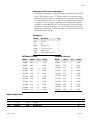
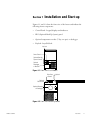
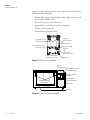
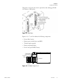
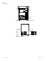
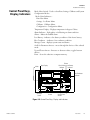
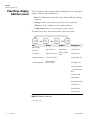
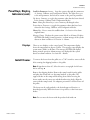
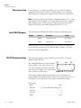

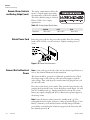
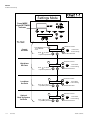
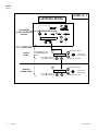
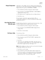

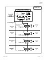
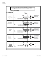
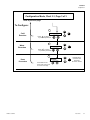

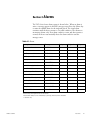
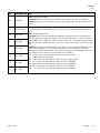
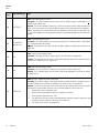
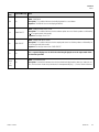


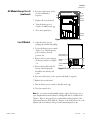

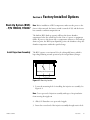
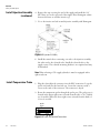
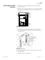
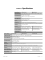
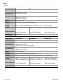
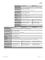


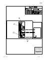
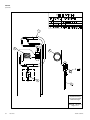
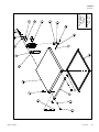

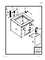
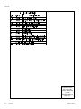
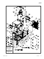
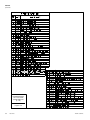
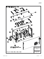

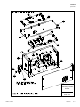
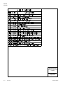
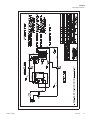
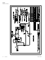
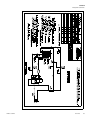
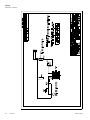
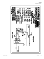

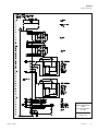
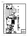
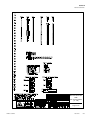
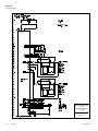
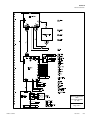
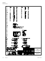
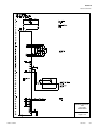
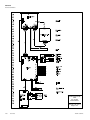
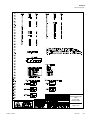
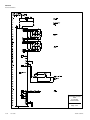
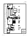

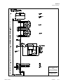

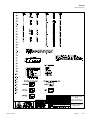
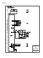

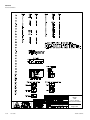
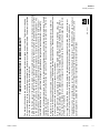
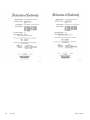

![TSC Series - User Manual [IT]](http://vs1.manualzilla.com/store/data/006117511_1-2773ea5de70324293bc89dec2c59e442-150x150.png)
![TSC Series - User Manual [ES]](http://vs1.manualzilla.com/store/data/006230477_1-11df1c39d3f2eebf5341d5bb9dc44b3c-150x150.png)
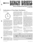
![TSD Series -40C ULT User Manual [EN]](http://vs1.manualzilla.com/store/data/005634658_1-66c9db561a67486106446026c707a26c-150x150.png)


![HFU B-Series -40C ULT User Manual [EN]](http://vs1.manualzilla.com/store/data/005939149_1-8517e65aa5244e7ea01bb15f66a7a44b-150x150.png)

![HFU B Series -86C ULT User Manual [EN]](http://vs1.manualzilla.com/store/data/005885768_1-df34a564309849efc50e986ca044a806-150x150.png)
![Revco ExF -86C ULT User Manual [EN]](http://vs1.manualzilla.com/store/data/005893203_1-9bb831e9c01339a2c9300ae02d73efa7-150x150.png)

![TSE Series -86C ULT Freezer User Manual [EN]](http://vs1.manualzilla.com/store/data/005901221_1-b339eb8511f0d627f85b4597dbd4f03d-150x150.png)