1
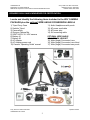
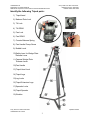
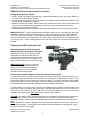
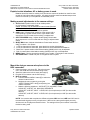
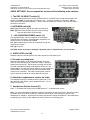
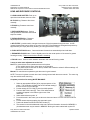
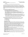
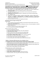
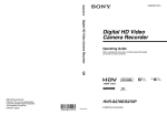
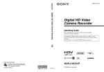
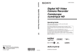
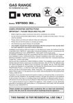
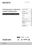
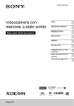
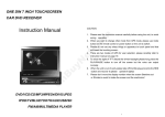
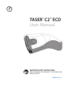
UHM Media Lab
2350 DOLE ST. KHET Studio B
WEB SITE: http://www.communications.hawaii.edu/mlab/about.htm
Sony HVR-V1U HDV Camcorder
Manager’s Phone: 956-3358
FRONT DESK: 956-3355
SONY HVR-V1U HDV CAMCORDER
STUDY GUIDE
PURPOSE
PURPOSE
This Study Guide was created to help Communication students to prepare for the HDV
Camcorder Certification exam, which is necessary to reserve and use the HDV remote
equipment, specifically for classroom purposes. This Study Guide provides all essential
information on the proper handling and use of the remote HDV equipment, including an
explanation of contents, procedures to demonstrate, and required features and techniques to
know.
"THE “GOLDEN RULES” OF THE UHM MEDIA LAB (REQUIRED KNOWLEDGE)
1. Never force anything! If something you are attempting to do requires any amount of
excessive force, STOP and review your methods.
2. Never over tighten! This may cause the stripping of threads. The use of excessive force
which can damage the equipment.
3. Never leave the camera equipment unattended! Camera and other video equipment
are prime targets for theft.
4. Never leave the camera equipment exposed to any heat source! e.g. - in the trunk
of a vehicle. Heat can cause tape to stretch. Excessive heat will cause camera parts to melt.
5. Never take the Media Lab equipment to the beach or near shorelines!
e.g. - where sand and salt air/spray can contact the equipment. Sand and salt air/spray
can clog and damage the sensitive equipment.
6. Never use equipment in “risky” situations/environments**! e.g. - any type of airborne
devices or locations including airplanes, helicopters, skateboards, motorcycles, rollerblades,
etc., night time shoots in low lit and/or unsafe areas, and “remote” areas which require
transport of equipment over rough terrain.
7. Never touch or attempt to clean the lens! There is a high probability of scratching
and permanently damaging the lens without the proper cleaning materials. Only use the
cleaning cloth provided.
8. Never aim the lens, the viewfinder, or the LCD screen directly at a strong light source!
This will cause permanent damage to the viewfinder/LCD screen. (e.g.- the sun, very bright
light, or its reflection from an object.)
Sony HVR-V1U HDV Camcorder
UHM Media Lab Tutorial
Updated 8/16/07
1
UHM Media Lab
2350 DOLE ST. KHET Studio B
WEB SITE: http://www.communications.hawaii.edu/mlab/about.htm
Sony HVR-V1U HDV Camcorder
Manager’s Phone: 956-3358
FRONT DESK: 956-3355
REQUIRED SKILLS AND KNOWLEDGE FOR CERTIFICATION
Locate and identify the following items included in the HDV CAMERA
PACKAGE plus the optional WIDE ANGLE CONVERSION LENS kit
1) Tripod Carry Case
2) Sachtler Tripod
3) Camera Bag
4) Shotgun Camera Mic
5) SONY HVR-V1U HDV camera
6) Battery #1
7) Battery #2
8) AC Adapter
9) AC Adapter power cord
10) Camera “Operating Guide” manual
11) Audio Headphones with pouch
12) AC power cord/cable
13) AC power strip
14) AV connecting cable
OPTIONAL WIDE ANGLE
CONVERSION LENS KIT
15) Wide (Angle) Conversion Lens
16) Wide (Angle) Conversion Lens Hood
17) Wide (Angle) Conversion lens pouch
Sony HVR-V1U HDV Camcorder
UHM Media Lab Tutorial
Updated 8/16/07
2
UHM Media Lab
2350 DOLE ST. KHET Studio B
WEB SITE: http://www.communications.hawaii.edu/mlab/about.htm
Sony HVR-V1U HDV Camcorder
Manager’s Phone: 956-3358
FRONT DESK: 956-3355
Identify the following Tripod parts:
1) Tripod head
2) Balance Plate Lock
3) Tilt Lock
4) Tilt DRAG
5) Pan Lock
6) Pan DRAG
7) Counter Balance Spring
8) Pan Handle Clamp Screw
9) Bubble Level
10) Safety lever for Wedge Plate
Release Lever
11) Camera Wedge Plate
Release Lever
12) Pan Handle
13) Tripod Head Lock
14) Tripod Legs
15) Leg Locks
16) Tripod Extension Legs
17) Spreader Locks
18) Tripod Speader
19) Buckles
Sony HVR-V1U HDV Camcorder
UHM Media Lab Tutorial
Updated 8/16/07
3
UHM Media Lab
2350 DOLE ST. KHET Studio B
WEB SITE: http://www.communications.hawaii.edu/mlab/about.htm
Sony HVR-V1U HDV Camcorder
Manager’s Phone: 956-3358
FRONT DESK: 956-3355
DEMONSTRATE the following Camera procedures:
Setting Up the Sachtler Tripod
1. Loosen, extend and re-tighten the tripod legs. Spread the tripod legs equally in one motion. Pulling out
one leg at a time will break the spreader.
2. Lock the tilt lock and pan locks, loosen the head lock, and adjust use the bubble level indicator to level
the tripod head. Re-tighten the head lock.
3. Mount the camera on the tripod. (Before mounting the camera to the tripod, make sure that the tilt lock
and pan lock are locked and all leg extensions are secured so that the tripod does not move or
collapse when mounting the camcorder.
4. Demonstrate safety procedure. Always double check tripod stability prior to mounting the camcorder.
IMPORTANT NOTE: To avoid potential accidents with tipping the tripod over, never leave the camcorder
unattended, especially when tripod head (tilt lock) is in an unlocked position. ALWAYS BE AWARE OF
THE STATUS OF THE TRIPOD! To avoid internal damage to the tripod head, never force a pan or tilt
when the tripod head is in a locked position. Also, always lay the tripod down when it is collapsed and not
in it’s carrying case. Tripods leaned against a wall or chair often fall over and end up with broken parts on
the head.
Setting Up the HDV Camcorder Unit
Demonstrate how to safely mount and
release the HDV Camcorder on the tripod.
From the back of the Tripod, slide the camera
wedge plate onto the tripod head. With your
free hand pull the wedge release lever to the left
while pushing up the lock lever. Carefully check
that the camera is securely mounted to the tripod.
IMPORTANT NOTE: The Pan Lock should
always remain unlocked after the camera is
secured to the tripod head to prevent the
accidental tipping over of the tripod if the
panhandle is accidentally pushed.
Hook up the AC power adapter and install and eject battery power.
To avoid pulling over the camera, start by working from the wall to the camera. Plug the extension cord
into the wall. Plug the power strip into the extension cord, making sure the power strip is turned off. Plug
the AC power adapter into the camera [f] (see picture on page 9). Connect the AC cable into the adapter
and the power strip. Turn on the power strip. Turn on the camera by pushing in on the lock release button
on the power switch and rotating the switch to point at the CAMERA designation.
To install a battery, turn off the camera, remove the AC adapter, lift the viewfinder. Insert the battery pack
with the arrow mark on the battery pack facing down. Slide the battery pack down until it is locked or you
hear a "click" sound. Now you can turn on the camera. To remove the battery, turn off the camera, lift the
viewfinder. While pressing the Batt Release button, slide the battery pack up.
CAUTION: If the battery pack is removed during recording or playback, the tape remains wound around
the video head cylinder and could become damaged. This is also the case during the loading and
unloading of the tape. Keep the power connected until the camera is switched off and completely shut
down.
NOTE: When the AC adapter is plugged into the camera and the camera is turned off, the battery on the
camera will be charged. A small yellow on the camera indicate that the battery is charging and it goes
out when the battery is fully charged.
Sony HVR-V1U HDV Camcorder
UHM Media Lab Tutorial
Updated 8/16/07
4
UHM Media Lab
2350 DOLE ST. KHET Studio B
WEB SITE: http://www.communications.hawaii.edu/mlab/about.htm
Sony HVR-V1U HDV Camcorder
Manager’s Phone: 956-3358
FRONT DESK: 956-3355
Explain in what situations AC or battery power is used.
Batteries should be used for mobility such as when the camera is handheld or used for short
periods of time before setting up again. AC power should be used for extended setups when
camera is to be set up in one place for an extended period.
Making manual adjustments to the camera settings
A. AUTO LOCK 3 position switch, set to middle position
up: All functions in automatic mode
middle: Functions may be switched to manual mode (Desired
position for Media Lab students)
down: Manually set functions locked into position
B. GAIN button: Increases light sensitivity of the camera with a
corresponding increase of video noise. Press button when
exposure is in AUTO mode and turn dial [F] to adjust level.
C. SHUTTER SPEED button: Adjusts shutter speed. Press button
when exposure is in AUTO mode and turn dial [F] to adjust shutter
speed.
D. WHITE BAL button: Adjusts white balance. Press button and turn
dial [F] to select 1 of 4 options.
1. A: Fill the frame with a white card, press the dial to set the white balance
2. B: Fill the frame with a white card, press the dial to set an alternate white balance
3. Black Dot: A preset outdoor white balance setting (5600K) which may be adjusted
4. Bulb: A preset indoor white balance setting (3200K) which may not be adjusted
E. MENU button: Push to access the camera’s menu system. Push again to exit the menu.
F. SEL/PUSH EXEC: Rotate and push to navigate the menu system.
Mount the shotgun camera microphone to the
HDV camcorder.
1. Open the shotgun mic clamp [G]. Place the shotgun
mic in the holder and secure the mounting screw.
2. Attach the cable to the built-in strain relief slot [H]
3. Plug the XLR connector into the XLR input [I]
4. Mic/Line setting.
a. Push the camera “MENU” button [E] to select the
camera’s internal menu
b. Navigate the menu system by turning the
“SELECT/PUSH EXEC” dial [F] and pushing it to
make the selection
c. Make the following selections: AUDIO SET; DV AU.MODE; FS48K
AUDIO SET; XLR SET; AU. MAN GAIN; SEPARATE
AUDIO SET; XLR SET; INPUT 1 LEVEL; MIC (for microphones) or LINE (for other audio
devices)
AUDIO SET; XLR SET; INPUT 2 LEVEL; MIC (for microphones) or LINE (for other audio
devices)
NOTE: You must be able to explain the difference between MIC level and LINE level. MIC level is
the weak audio signal put out by microphones. LINE level is a strong audio signal put out by
devices such as CD players and audio mixers. The settings of the input connector must match
the device being used.
Sony HVR-V1U HDV Camcorder
UHM Media Lab Tutorial
Updated 8/16/07
5
UHM Media Lab
2350 DOLE ST. KHET Studio B
WEB SITE: http://www.communications.hawaii.edu/mlab/about.htm
Sony HVR-V1U HDV Camcorder
Manager’s Phone: 956-3358
FRONT DESK: 956-3355
AUDIO SETTINGS: Set and explain the functions of the following audio switches:
1. The REC CH SELECT switch [J]
This switch determines how the audio from audio INPUT1 and INPUT2 are routed and recorded in the
camera. CH1-CH2 [1] mixes audio to Channel 1 only… nothing is recorded on Channel 2. CH1 [2]
allows audio to be recorded separately… INPUT1 audio is recorded on Channel 1 and INPUT2 audio is
recorded on Channel 2.
2. AUTO/MAN switch [K]
AUTO: [3] Automatically adjusts the audio recording level
MAN: [4] Allows manual control over the audio recording
level with the AUDIO LEVEL dial [M]
3. +48V (PHANTOM POWER) switch. [L]
The supplied shotgun mic is a condenser mic and needs
electrical power to function. Electrical power supplied by the
camera is known as PHANTOM POWER.
ON: [5] Provides phantom power to microphone through the
audio input connector
OFF: [6] No power
CAUTION: Some mics may be damaged if phantom power is supplied when it is not needed.
4. AUDIO LEVEL dial. [M]
Rotate to adjust the recording level of the audio signals from the audio inputs.
5. Set audio recording level
Open the LCD PANEL on the side of the camera. Push the
STATUS CHECK button [U] and select the “AUDIO” display by
rotating the menu dial [F]. Set the audio recording level so that
the meter indicates an average level between 30 and 10 in the
meter readout. You can also monitor audio by cycling through the
DISPLAY/BATT INTO button [Q] and using the smaller audio
monitor in the viewfinder. The audio recording level is set too
high if it touches the red bar and audio distortion will occur.
6. Attach the headphones to monitor the audio
The headphone jack [S] is located under the guard cap on the
back left side of the camera. Use a headphone with a 3.5 mm
stereo mini jack only.
7. Headphones Volume Control [O]
Push “+” to increase the volume to the headphones and “-“ to decrease the volume.
Note: You must understand the difference between recording level and volume level. Recording level is
the setting at which the audio recording is made and volume level is the setting for loudness in the
headphones or speakers. Adjusting the recording level will also change the loudness in the headphones,
but adjusting the volume for the headphones has no effect on the recording level.
Sony HVR-V1U HDV Camcorder
UHM Media Lab Tutorial
Updated 8/16/07
6
UHM Media Lab
2350 DOLE ST. KHET Studio B
WEB SITE: http://www.communications.hawaii.edu/mlab/about.htm
Sony HVR-V1U HDV Camcorder
Manager’s Phone: 956-3358
FRONT DESK: 956-3355
LENS AND EXPOSURE CONTROLS:
V. LENS HOOD SHUTTER: Push up to
open lens hood shutter, down to close
W. FOCUS ring: Rotate to focus lens
manually.
X. ZOOM ring: Rotate to zoom lens
manually.
Y. EXPOSURE/IRIS button: Push to
change between automatic and manual
exposure modes.
Z. EXPOSURE/IRIS dial: Rotate to
adjust exposure in manual mode.
a. ND FILTER: 3 position switch changes the amount of light that passes through the lens. An ND
(neutral density) filter has no effect on the color of the light. Each adjustment changes the exposure by
approximately 2 F stops (effectively doubling or halving the amount of light)
b. PUSH AUTO FOCUS button: One touch button focuses lens automatically when held down.
c. EXPANDED FOCUS button: Push to digitally zoom into the center portion of the scene for greater
focusing accuracy. Does not work when camera is recording.
d. FOCUS button: Push to switch between automatic and manual focusing modes
3 ways to make zoom adjustments to the lens
Servo: For motor driven zoom operations there are 2 options
1) The variable power zoom rocker lever on the handgrip
2) The power zoom rocker lever on the top handle with a switch to select 3 different settings: off,
slow zoom, and fast zoom
Manual: For manual zoom operations grab the zoom ring and rotate it.
NOTE: The zoom ring does not work when lens is being zoomed with the servo controls. The zoom ring
may also exhibit some control lag.
Complete procedure for setting WHITE BALANCE
1. Select an appropriate ND filter [a] for proper exposure of the
scene. The viewfinder will flash with an ND indicator setting if
there is too much or too little light.
2. Put the camera AUTO LOCK [A] into the middle position.
3. Push the WHT BAL button [D]. One of four white balance
symbols will appear in the bottom right corner of the
viewfinder.
4. Select white balance symbol “A”
5. Put a white card in the scene you are about to shoot and zoom in on the card until it fills the
frame
6. Put the camera exposure setting into automatic mode
7. Press and release the SEL/PUSH EXEC button [F]
8. The camera is now white balanced to the scene and the information is stored in MEMORY A.
(An alternate scene may be stored in MEMORY B using the same method with symbol “B”
Sony HVR-V1U HDV Camcorder
UHM Media Lab Tutorial
Updated 8/16/07
7
UHM Media Lab
2350 DOLE ST. KHET Studio B
WEB SITE: http://www.communications.hawaii.edu/mlab/about.htm
Sony HVR-V1U HDV Camcorder
Manager’s Phone: 956-3358
FRONT DESK: 956-3355
selected.)
9. Put the camera into manual exposure mode for proper exposure setting
Understanding WHITE BALANCE: Light consists of 3 different primary colors. The balance of these
different colors can shift depending on the light sources and environment. A video camera is usually
more sensitive to these differences than the human eye. When the camera is white balanced on a white
card, the card will be white in the video and all other colors will appear normal. A white balance “SUN”
symbol is set for an approximation of outdoor light with the sun shining at noon (5200K). A white balance
“INDOOR” symbol is set for an approximation of TV studio or stage lighting (without colored gels)
(3200K).
Standard procedure for setting the correct exposure
10. Set the Push the EXPOSURE/IRIS button [Y] to switch to manual control of the exposure
11. Rotate the EXPOSURE/IRIS dial to set the proper exposure
12. Use the ZEBRA switch [P] to assist in setting the proper exposure
*When the ZEBRA switch is set to 100, images that are over exposed lose their color and
definition and go totally white and have a “zebra pattern” on them in the viewfinder.
*When the ZEBRA switch is set to 70, a human face is properly exposed when a “zebra pattern”
just starts to appear on the face in the highlighted areas, it is especially noticeable between the
brows and on bridge of the nose.
13. Use additional lights and reflectors to achieve proper exposure in high contrast lighting
situations. For example, shooting a person’s headshot for an interview with the sun behind them
and sky as background… if the sky is properly exposed, the face will be too dark and if the face
is properly exposed, the sky will be “blown out’ to white plus the face will often shift to a reddish
tint. Adding more light to the face will help balance out the brightness of the sky.
Standard procedure for setting time code Time Code is set in the menu system “TC/UB SET”
14. Push MENU button [E], rotate SEL/PUSH EXEC dial [F] and push to select your choices
15. Select and push TC/UB SET: TC PRESET: PRESET: set to 01:00:00:00: OK: OK
16. TC FORMAT: DF
17. TC RUN: REC RUN
18. TC MAKE: PRESET
Understanding TIME CODE:
TC FORMAT: DF DF stands for Drop Frame. DF time code eliminates (or drops) 2 time counted
th
frames (0 & 1) every minute, except for every 10 minute to synchronize the time code with real time.
Although 30 frames are considered to be one second in time code processing, the actual frame rate
is 29.97 frames/second. As a result, the time code gradually lags behind real time as the recording
gets longer. The drop frame function adjusts the time code to match the real time.
TC FORMAT: NDF Without dropping time counted frames (known as NDF or Non-Drop Frame
mode) our time code will read 1 hour, but in real clock time it would equal that of 1 hour and 3.6
seconds (108 extra frames of video). (When shooting in 24P, the non-drop frame mode is
established regardless of this item's setting.) To learn more about setting Time Code refer to pages
78-79 of user manual.
TC RUN: REC RUN Record run is the advancement of time code only when recording video. With
this setting, 1 hour of time code yields 1 hour of video on tape.
TC RUN: FREE RUN Free run will advance the time-code continuously whether recording or not.
This method is often chosen to match the time during the day when the recording was made by
synching the time code with the time of day.
TC MAKE: PRESET Allows the camera operator to set the time code which is to be recorded at the
beginning of the tape. After that, the last recorded time code becomes the time code when recording
restarts.
TC MAKE: REGENERATE: recording proceeds in such a way that the time code continues (is
regenerated) from the time code on the tape. However, it must be cued to that video and time code.
Sony HVR-V1U HDV Camcorder
UHM Media Lab Tutorial
Updated 8/16/07
8
UHM Media Lab
2350 DOLE ST. KHET Studio B
WEB SITE: http://www.communications.hawaii.edu/mlab/about.htm
Sony HVR-V1U HDV Camcorder
Manager’s Phone: 956-3358
FRONT DESK: 956-3355
Using ASSIGN buttons [R] [e]
ASSIGN buttons can be used to trigger certain functions of your choice. These assignments are
made in the MENU system. The Media Lab suggests that 3 buttons assume the following
functions. You may use the other 3 assignable buttons for functions of your choice.
1. COLOR BARS changes the video input to color bars
2. RECORD REVIEW allows you to view the last 2 seconds of the last recorded scene
3. END SEARCH cues up the tape to the last recorded video
Attaching the AV CABLE
You can monitor video on a standard (4:3) monitor using this
cable (see item #14 on page 2). Plug it into the back of the
camera [e], above the external power connector [f].
Loading videotape
Use only SONY brand videotape! All other brands are not
recommended due to incompatibility issues. SONY Digital
Master or DVCAM tape is recommended, although consumer
grade SONY tape will work if necessary. Slide and hold the OPEN/EJECT button on the top of
the handgrip and pull open the lid. Wait for the cassette compartment to open up. Insert video
cassette with it’s window facing out, then press where it says “PUSH” on the side of the
compartment. Close the handgrip lid and you are ready to begin taping.
Tape playback
After recording video, press the green button on the camera power switch and move the lever to
the VCR mode. Use the VCR control buttons [N] to rewind and playback the video on the tape.
Use “END SEARCH” to re-cue the tape to the last video.
Attaching optional WIDE ANGLE CONVERSION LENS [E]+[G]
1. When the camera is mounted
on a tripod, tilt it upwards and
lock the pan and tilt locks (do
not point the camera into the
sun or a bright light source)
2. Remove the camera lens hood
(loosen the lens hood fixing
screw and turn the lens hood
counterclockwise an 1/8 turn
and pull off)
3. Remove (unscrew) and store
camera lens protection filter
4. Attach WIDE ANGLE
CONVERSION LENS [g]: align
marks on WA (Wide Angle)
lens and top of camera lens,
slip WA lens [g] over camera
lens and rotate clockwise
about 1/8 turn until it locks into
place
5. Attach WA CONVERSION lens hood [i]: Loosen WA hood locking screw [j], align marks at the
top, slip hood onto lens and tighten locking screw [j]
6. Removal is this process reversed except that the WA lens locking button [h] must be pushed to
release and turn the WA lens.
Sony HVR-V1U HDV Camcorder
UHM Media Lab Tutorial
Updated 8/16/07
9
UHM Media Lab
2350 DOLE ST. KHET Studio B
WEB SITE: http://www.communications.hawaii.edu/mlab/about.htm
Sony HVR-V1U HDV Camcorder
Manager’s Phone: 956-3358
FRONT DESK: 956-3355
Check important camera settings before shooting begins. NOTE: The Media Lab staff will not be
responsible for any settings of the camera. The students will be responsible for setting up the
camera for their use. The following are recommended settings suggested by the Media Lab.
Consult your instructor if you have any questions about the proper settings for your class.
1. REC FORMAT: DV | DV REC MODE: DVCAM | DV WIDE REC: OFF | This is the Media Lab’s
currently recommended video format setting (consult your class instructor)
2. Audio format: 48HZ
3. AU. MAN GAIN: SEPARATE (Allows manual audio controls to adjust audio record levels
separately for channels 1 and 2)
4. STEADYSHOT: OFF (Off when mounted on a tripod but may be useful for handheld shots)
5. PICT. PROFILE: OFF
6. ASSIGN BTN: ASSIGN4:COLORBAR | ASSIGN5: REC REVIEW | ASSIGN 6: END SEARCH
7. Time code: “TC FORMAT” to “DF” (drop frame); “TC PRESET” to 00:00:00 or 01:00:00 at start
of tape (or set “TC MAKE” to “REGENERATE” and cue up the end of the last recorded video to
record a continuous time code.
8. Record 30 seconds of color bars at the beginning of the tape.
Standard procedures to begin shooting video
Preset camera:
9. Turn on camera and set all important settings such as audio and video format choices, scene
profiles, time code preferences, etc.
10. Set personal camera preferences such as headphones volume, LCD panel brightness, viewfinder
diopter adjustment, etc.
11. Put tape in camera and rewind if tape was previously used
12. Turn on and record 30 seconds of COLOR BARS
Setup for shooting video on location
13. Hook up microphones to be used
14. Set proper audio recording levels and monitor with headphones
15. Set proper ND filter selection
16. Zoom in and focus on a white card in front of the subject matter
17. Set exposure to AUTO and set white balance with white card
18. Focus lens on subject matter in manual mode for maximum sharpness
19. Zoom back to compose scene to shoot
20. Set exposure to manual control and adjust for proper exposure
21. Record video while monitoring audio with headphones
22. Stop recording and check recorded video with REC REVIEW function
“Striking” / Packing the HDV Camcorder Unit and Sachtler Tripod
A. Demonstrate how to “strike” the HDV Camcorder unit when the video shoot is finished
• The tape must be remove, the camera turned off, and the battery must be removed
• The wide angle lens must be removed and stored correctly and the camera protection filter and lens
hood must be reattached, the lens hood shutter should be closed
• The AC cord must be coiled in the “over/under” method of coiling. (All audio and video cables must
be coiled in the same manner to prevent twisting when unwound.)
• All items must be neatly packed in their proper locations
B. Demonstrate how to “strike” the Sachtler tripod.
• The spreader extensions must be retracted and locked
• The tripod legs must be retracted and locked
• The legs must be collapsed and centered
• The pan handle is loosened and dropped to the side of the tripod
• The tripod is placed in the carrying case with tilt and pan unlocked
Sony HVR-V1U HDV Camcorder
UHM Media Lab Tutorial
Updated 8/16/07
10