1
Danaher Motion
Single-Axis Brushless Servo Drive
PCE830/40 User Manual
Pacific Scientific
Part Number: MAE800
Document Number: M-PE-800-0301
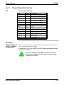
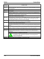
Record of Manual Revisions
ISSUE NO. DATE
0
1
BRIEF DESCRIPTION OF REVISION
Preliminary issue for review
Initial release
Copyright Information
© Copyright 2002 Pacific Scientific - All rights reserved.
Printed in the United States of America.
NOTICE:
Not for use or disclosure outside of Pacific Scientific Company except under written agreement. All rights are
reserved. No part of this book shall be reproduced, stored in retrieval form, or transmitted by any means,
electronic, mechanical, photocopying, recording, or otherwise without the written permission from the publisher.
While every precaution has been taken in the preparation of the book, the publisher assumes no responsibility for
errors or omissions. Neither is any liability assumed for damages resulting from the use of the information
contained herein.
This document is proprietary information of Pacific Scientific Company that is furnished for customer use ONLY.
No other uses are authorized without written permission of Pacific Scientific Company. Information in this
document is subject to change without notice and does not represent a commitment on the part the Pacific
Scientific Company. Therefore, information contained in this manual may be updated from time-to-time due to
product improvements, etc., and may not conform in every respect to former issues.
Limited Warranty
Includes software provided by Pacific Scientific
Seller warrants that the Goods sold hereunder are free from defects in material and workmanship for the product
warranty period of each item of Goods (Product Warranty Periods are listed below). Seller warrants its Good(s)
only to the original purchaser (the “Customer”), and in the case of original equipment manufacturers or
distributors, only to their original consumer (the “Customer”). There are no warranties whatsoever on Goods
built or acquired, wholly or partially, to a buyer’s designs or specifications
This express warranty is in lieu of and exclude all other warranties, express or implied, by operation or law or
otherwise including THE WARRANTY OF MERCHANTABILITY AND FITNESS FOR A PARTICULAR
PURPOSE (WHETHER KNOWN TO SELLER OR NOT), all other such warranties being hereby expressly
disclaimed by Seller and waived by Buyer.
Written notice of claimed defects shall have been given to Seller within the period set forth in the schedule below,
and within thirty (30) days from the date any such defect is first discovered.
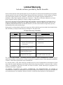
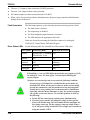
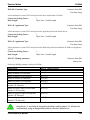
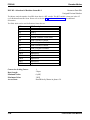
Product Warranty Schedules
Brand
Products
Warranty Period
Pacific
Scientific
All Products
24 months from date of
manufacture
Superior
All Products
12 months from date of
manufacture
Kollmorgen
Standard Brush-type
Motors, Electronics and
Accessories
12 months from date of
manufacture
Kollmorgen
Standard Brushless Motors, 24 months from date of manufacture
Electronics and Accessories
Kollmorgen
Standard Step Motors, Stepper 12 months from date of manufacture
Controls and Accessories
Kollmorgen
Custom Motion Systems or To be negotiated on a case-by-case
components of any type
basis, and set forth in the order.
The Good or parts claimed to be defective must be returned to Seller, accompanied by a Return Material
Authorization (RMA) issued by Seller’s facility responsible for supplying Goods, with transportation prepaid by
Customer, with written specifications of the claimed defect.
If a warranty claim is valid, Seller shall pay reasonable one-way costs of transportation of the defective Goods
from either the original destination or the location where defect occurred, whichever is closest to Seller’s facility.
Under no circumstances shall Seller be liable for removal of Seller’s Goods from Buyer’s equipment or reinstallation into Buyer's equipment.
NO PERSON, INCLUDING ANY AGENT, DISTRIBUTOR, OR REPRESENTATIVE OF SELLER, IS
AUTHORIZED TO MAKE ANY REPRESENTATION OR WARRANTY ON BEHALF OF SELLER CONCERNING
ANY GOODS MANUFACTURED BY SELLER, EXCEPT TO REFER PURCHASERS TO THIS WARRANTY.
SOFTWARE WARRANTY
Computer software programs that may be included in material or Goods sold to Buyer have been designed to
perform a given set of tasks as defined in the documentation provided and are offered AS IS. It is Buyer’s
responsibility to determine if the features of the software programs are suitable for Buyer’s requirements and must
confirm that the software programs operate correctly. Buyer understands that such software programs are of such
complexity that they may have inherent defects and that Seller makes no warranty that all software features will
perform correctly as supplied. For Seller’s software utilizing automation servers, improper reading and writing
data to the automation server can cause the automation server software to malfunction and may cause the
automation server and/or the program writing to the automation server to crash. Improperly reading and writing
data to an automation server may cause the device controlled by that automation server to malfunction. Seller
shall not be responsible for damage to any device or damage caused by any device due to the improper reading
and/or writing of data to an automation server.
LIMITATION OF LIABILITY
NOTWITHSTANDING ANYTHING TO THE CONTRARY, SELLER SHALL NOT BE LIABLE FOR ANY
SPECIAL, INCIDENTAL, INDIRECT OR CONSEQUENTIAL DAMAGES INCLUDING LOST PROFITS
ARISING OUT OF THE PERFORMANCE, DELAYED PERFORMANCE OR BREACH OF PERFORMANCE
OF THIS ORDER REGARDLESS WHETHER SUCH LIABILITY BE CLAIMED IN CONTRACT, EQUITY,
TORT OR OTHERWISE. SELLER’S OBLIGATION IS LIMITED SOLELY TO REPAIRING OR
REPLACING (AT ITS OPTION AND AS SET FORTH IN SECTION 10 AND SECTION 11), AT ITS
APPROVED REPAIR FACILITY, ANY GOODS OR PARTS WHICH PROVE TO SELLER’S
SATISFACTION TO BE DEFECTIVE AS A RESULT OF DEFECTIVE MATERIALS OR WORKMANSHIP,
IN ACCORDANCE WITH SELLER’S STATED WARRANTY. IN NO EVENT SHALL SELLER’S
LIABILITY EXCEED THE TOTAL PURCHASE PRICE SET FORTH IN THIS ORDER.
GENERAL INDEMNITY
Buyer agrees to hold Seller harmless from any and all liability, and to pay all costs and attorney’s fees, for injury
or damage to persons or property caused in any manner by Goods covered by the order while in possession or
under the control of Buyer or Buyer’s successor in interest.
SAFETY
The equipment described herein has been developed, produced, tested and documented in accordance
with the corresponding standards. During use conforming with requirements, the equipment is not
dangerous for people or equipment. Use conforming with requirements means that the safety
recommendations and warnings detailed in this manual are complied with and applicable regulations for
safety (machine directives, etc.) and noise suppression (EMC Directives) are observed while operating
the drive. At the end of its lifetime, dispose of or recycle the drive according to the applicable
regulations.
Installation and wiring of the drive must be completed only by qualified personnel having a basic
knowledge of electronics, installation of electronic and mechanical components, and all applicable
wiring regulations.
Commissioning of the machine utilizing the drives must be done only by qualified personnel having a
broad knowledge of electronics and motion control technology.
As the user or person applying this unit, you are responsible for determining the suitability of this
product for the application. In no event is the Pacific Scientific Company responsible or liable for
indirect or consequential damage resulting from the misuse of this product.
Read this manual completely to effectively and safely operate the PCE830/40.
Comply with the applicable European standards and Directives. In Germany, these include:
●
DIN VDE 0100 (instructions for setting up power installations with rated voltages below 1000V).
●
DIN - EN 60 204 - Part 1, (VDE 0113, part 1) instructions relative to electric equipment in
machines for industrial use.
●
DIN EN 50178, (VDE 0160) equipping high-voltage current installations with electronic operating
means.
Safety Requirements
The following requirements must be met to ensure compliance with the Low Voltage Directive:
●
380/400/480VAC mains must be balanced, three-phase, WYE-type with earthed neutral.
●
Never connect or disconnect any drive connectors or terminals while the power is switched on.
●
The climatic conditions shall be in accordance with EN 50178 climatic class: Type B,
temperature and relative humidity: Class 3K3.
●
This drive is to be installed inside a motor/control cabinet accessible only by qualified personnel.
●
Electronic drives contain electrostatic-sensitive devices that can be damaged when handled
improperly. Qualified personnel must follow ESD protection measures. For example, wear
grounded heel and wrist straps when contacting drive.
●
The discharge time for the bus capacitors may be as long as 5 minutes. After disconnecting the
drive from the AC mains, wait at least 5 minutes before removing the drive’s cover and exposing
live parts.
●
Follow IEC 536-2 and IEC 1140 for installation protection against electric shock.
●
Installation shall be performed in accordance with local electric codes, local accident prevention
rules, EN 50178 and EN 61800-3.
●
Due to high leakage current, this drive is to be permanently installed (hard wired). The PE
connection shall be made by two separate conductors between the earth ground and the two PE
terminals on the device.
●
Consult the factory before using this product on a circuit protected by a residual-current-operated
protective device (RCD).
●
External, supply line fusing is required. PCE8x3: Bussman, KTK-20, PCE8x5: Bussmann
KTK-30.
●
Motor cable shield must be connected to protective earth.
●
All covers shall be closed during operation.
●
During periods of extreme regeneration or excessively high input voltage, the temperature of the
regen resistor may exceed 70 °C.
●
When using an external regen resistor, if regen cabling is accessible during normal machine
operation, the regen resistor cable should be rated at 600VDC or higher and shielded with the
shield connected to PE.
Danaher Motion
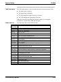
Table of Contents
Contents
1.
MOUNTING AND INSTALLATION ....................................................................................... 1-1
1.1.
INSTALLING THE PCE800 SERVO DRIVE .................................................................................. 1-2
1.1.1. Mounting the Drive .............................................................................................................. 1-2
1.1.2. Connecting to AC Power ..................................................................................................... 1-6
1.1.3. Connection to PE Ground.................................................................................................... 1-7
1.1.4. Grounding Shields for Safety and Low Emissions and Susceptibility ................................. 1-8
1.1.5. Grounding the Motor Case .................................................................................................. 1-8
1.1.6. Long Motor Power Cables and Baluns................................................................................ 1-9
1.2.
SAFE OPERATION OF THE DRIVE ............................................................................................ 1-10
2.
PCE830.......................................................................................................................................... 2-1
2.1.
800TOOLS ................................................................................................................................ 2-1
2.1.1. Installing 800Tools .............................................................................................................. 2-1
2.1.2. Starting 800Tools................................................................................................................. 2-1
2.1.3. Getting Around in 800Tools................................................................................................. 2-2
2.1.4. Configuring Your System ..................................................................................................... 2-3
2.1.5. Configuring Your Drive ....................................................................................................... 2-4
2.1.6. Changing Variables On-Line............................................................................................... 2-9
2.1.7. Uploading Parameters from the PCE830.......................................................................... 2-10
2.1.8. Edit a Configuration File................................................................................................... 2-10
2.1.9. Editing The Motor Database ............................................................................................. 2-11
2.1.10. Tuning Wizard ................................................................................................................ 2-12
2.1.11. Exiting 800Tools............................................................................................................. 2-12
2.2.
INTERFACES AND CONNECTIONS ............................................................................................ 2-12
2.2.1. Power Board Connector .................................................................................................... 2-13
2.2.2. Serial Port.......................................................................................................................... 2-16
2.2.3. Command I/O..................................................................................................................... 2-21
2.2.4. Base Servo Drive User I/O Connections ........................................................................... 2-36
2.3.
MAPPABLE I/O FUNCTIONS .................................................................................................... 2-38
2.4.
SELECTING MODES OF OPERATION ........................................................................................ 2-55
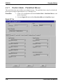
2.4.1. Position Mode - Predefined Moves.................................................................................... 2-56
2.4.2. Position Mode - Step and Direction................................................................................... 2-62
2.4.3. Position Mode - Electronic Gearing.................................................................................. 2-64
2.4.4. Velocity Mode - Analog Command .................................................................................... 2-66
2.4.5. Velocity Mode - Frequency Command .............................................................................. 2-67
2.4.6. Velocity Mode - Serial Command ...................................................................................... 2-67
2.4.7. Torque Mode - Analog Command...................................................................................... 2-68
2.4.8. Torque Mode - Frequency Command ................................................................................ 2-69
2.5.
TUNING .................................................................................................................................. 2-69
2.5.1. Current Loop Settings ........................................................................................................ 2-69
2.5.2. Velocity Loop Settings........................................................................................................ 2-70
2.5.3. Position Loop Settings ....................................................................................................... 2-72
2.5.4. Manual Tuning with SoftScope .......................................................................................... 2-73
2.5.5. High Inertial Load ............................................................................................................. 2-82
PCE830/40 User Manual
i
Table of Contents
Danaher Motion
2.5.6. Mechanical Resonance ...................................................................................................... 2-83
2.5.7. Inertia and Bandwidth ....................................................................................................... 2-85
2.6.
DIAGNOSTICS AND PROTECTION CIRCUITS ............................................................................. 2-87
2.6.1. FaultCode List ................................................................................................................... 2-89
2.6.2. Fault LED Troubleshooting............................................................................................... 2-91
2.7.
SERVO LOOP PARAMETERS .................................................................................................... 2-93
2.7.1. Velocity Loop ..................................................................................................................... 2-93
2.7.2. Position Loop ..................................................................................................................... 2-99
2.7.3. Advanced Velocity Loop Tuning ...................................................................................... 2-102
2.8.
COMCODER OR ENCODER FEEDBACK SETUP ........................................................................ 2-104
2.8.1. Configuring the PCE830 for a Motor with an Incremental Encoder .............................. 2-104
2.8.2. Configuring the PCE830 for a Motor With a Comcoder................................................. 2-106
2.9.
SIMPLE ASCII PROTOCOL .................................................................................................... 2-107
2.9.1. Pre-defined Identifiers ..................................................................................................... 2-109
3.
PCE840.......................................................................................................................................... 3-1
3.1.
SETTING UP INTENSITY AND BAUD RATE USING SW4 ............................................................. 3-1
3.2.
SETTING UP SERIAL ADDRESSES USING SWITCHES SW5 AND SW6......................................... 3-2
3.3.
IDENTIFICATION NUMBERS (IDNS) .......................................................................................... 3-4
3.4.
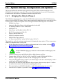
SYSTEM STARTUP, CONFIGURATION AND UPDATES ................................................................. 3-9
3.4.1. Bringing the Ring to Phase 4 ............................................................................................... 3-9
3.4.2. 800TOOLS PCE840 Setup................................................................................................. 3-10
3.4.3. C840 Flash (F/W) Update ................................................................................................. 3-14
3.5.
INTERFACES AND CONNECTIONS ............................................................................................ 3-15
3.5.1. Power Board Connector .................................................................................................... 3-16
3.5.2. Serial Port.......................................................................................................................... 3-19
3.5.3. Command I/O..................................................................................................................... 3-22
3.5.4. Feedback ............................................................................................................................ 3-35
3.6.
INPUTS AND OUTPUTS ............................................................................................................ 3-38
3.6.1. General Purpose Inputs/Outputs ....................................................................................... 3-38
3.6.2. Probe/Registration Functionality ...................................................................................... 3-42
3.6.3. Analog Input....................................................................................................................... 3-45
3.6.4. Analog Outputs .................................................................................................................. 3-45
3.6.5. DACMap Parameters......................................................................................................... 3-46
3.7.
SERVO LOOP PARAMETERS .................................................................................................... 3-49
3.7.1. Current Loop...................................................................................................................... 3-49
3.7.2. Velocity Loop ..................................................................................................................... 3-49
3.7.3. Position Loop ..................................................................................................................... 3-55
3.7.4. Advanced Velocity Loop Tuning ........................................................................................ 3-58
3.8.
IDN ATTRIBUTES ................................................................................................................... 3-60
3.8.1. SERCOS-Specific Parameters ........................................................................................... 3-60
3.8.2. Manufacturer-Specific IDNs.............................................................................................. 3-99
3.9.
DIAGNOSTICS AND PROTECTION CIRCUITS ........................................................................... 3-126
3.9.1. Troubleshooting ............................................................................................................... 3-129
3.9.2. Motor Commutation......................................................................................................... 3-131
3.9.3. System Protection............................................................................................................. 3-132
4.
MODEL IDENTIFICATION ..................................................................................................... 4-1
4.1.
ii
BASIC SERVO DRIVE PACKAGE ORDER NUMBERING SYSTEM.................................................. 4-1
PCE830/40 User Manual
Danaher Motion
4.2.
4.3.
5.
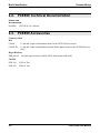
PCE800 TECHNICAL DOCUMENTATION ................................................................................... 4-2
PCE800 ACCESSORIES ............................................................................................................. 4-2
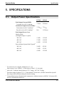
SPECIFICATIONS...................................................................................................................... 5-1
5.1.
5.2.
5.3.
5.4.
6.
Table of Contents
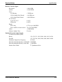
OUTPUT POWER SPECIFICATIONS ............................................................................................. 5-1
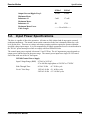
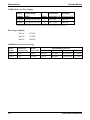
INPUT POWER SPECIFICATIONS ................................................................................................ 5-3
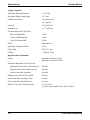
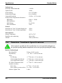
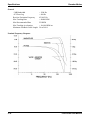
PERFORMANCE CHARACTERISTICS ........................................................................................... 5-5
RESOLVER FEEDBACK SPECIFICATIONS.................................................................................... 5-8
USING EXTERNAL REGEN .................................................................................................... 6-1
INDEX.........................................................................................................................................................I
PCE830/40 User Manual
iii
Table of Contents
Danaher Motion
This page intentionally left blank.
iv
PCE830/40 User Manual
Danaher Motion
Mounting and Installation
1. MOUNTING AND INSTALLATION
This section provides information on mounting and installing the equipment as well as grounding and
bonding requirements.
The equipment is not ready to operate without additional installations (cable, motor, etc.). All necessary
tests and measurements must be made on a typical installation. The test installation (with all peripheral
devices), as well as the test results and measurements are recorded in detail in documentation available
on request from the manufacturer.
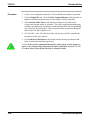
If the connection method on your machine is different from what is contained in this
document, or in the event of use of components other than those that we have specified,
adherence to interference limit values cannot be guaranteed.
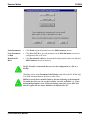
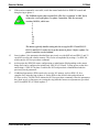
To go through this procedure, you will need the following items.
♦ PCE830/40 Servo Drive
♦ Appropriate Brushless Motor with nothing attached to the shaft
♦ PC Running Windows 95/98, Windows 2000, or WindowsNT
♦ 800Tools Installation Disk
♦ Motor Power and Feedback Cables (TB1, J3)
♦ RS-232 Communications Cable (J1)
♦ DB-44 Connector Mate (J2)
♦ AC Power Line (TB1)
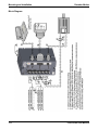
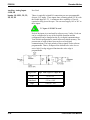
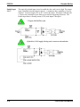
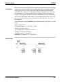
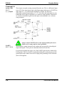
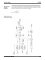
Wiring
Connections
Connect the motor, feedback, and AC Power cables as shown in the following
Connection Diagram but do not apply the AC Power at this time. It is highly
recommended that Pacific Scientific motor and feedback cables be used during setup
since improper cabling is the number one cause of start up problems.
The RS-232 cable made by Pacific Scientific (order number CS-232-5600) can be used
to connect the 9-pin serial port socket on the PCE830/40 to the PC. If this cable is
unavailable, a simple 3 wire cable can be made using the wiring diagram shown on
page 1-3.
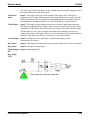
If you are using the drive’s +24VDC supply, connect I/O RTN (J2-38) to +24VDC
output RTN (J2-39).
The last connection needed is to provide the hardware enable to the PCE830/40 via J237 and +24V on J2-40. Preferably connect a toggle switch between J2-37 and J2-40. If
a toggle switch is not available a clip lead that can connect or not connect J2-40 to J237 will do.
PCE830/40 User Manual
1-1
Mounting and Installation
1.1.
Danaher Motion
Installing the PCE800 Servo Drive
Much of the connection information presented in this section is contained in Section 2.2,
Interfaces and Connections.
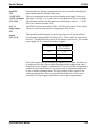
1.1.1. Mounting the Drive
The PCE830/40 drives are designed for operation in a cabinet. Follow these installation
instructions:
●
Mount the drives vertically inside a cabinet on a flat, solid, electrically conductive,
mounting surface connected to PE (protective earth ground) and capable of
supporting the weight of the unit.
●
Remove the paint on the mounting surface over an area extending at least 12 mm
(0.5”) from the mounting bolts to achieve good electrical connection over a large area
between the drive and grounded mounting surface.
●
Install conductive clamps near the drive on the mounting panel (ground plane) for
electrically connecting the outer shield of certain cables (defined below) to the panel.
The conductive clamps can also be attached to PE on the front of the drive. Remove
about 10mm (0.5”) of the outer jacket of these cables where the clamp will be
exposed to the braided shield before inserting under the clamp and tightening. The
length of the cable between the drive connection and the clamp should be as short as
possible (not exceeding 0.6 meters (two feet)). If a ground plane is available at the
other end of these cables, use a conductive clamp at that end to connect the shield to
that ground plane as well.
●
Provide a minimum unobstructed space of 100 mm (4”) above and below the drive.
With convection cooling, provide 40mm (1.6”) free space on either side of each unit.
With forced air cooling, provide 25mm (1") free space on the side of the drive with
the heat sink.
●
Insure the environment within the cabinet meets the requirements defined in the
Specifications section.
1-2
PCE830/40 User Manual
Danaher Motion
Mounting and Installation
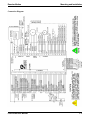
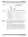
Connection Diagram
PCE830/40 User Manual
1-3
Mounting and Installation
Danaher Motion
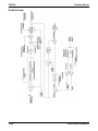
Block Diagram
1-4
PCE830/40 User Manual
Danaher Motion
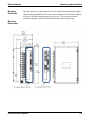
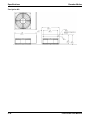
Mounting
Guidelines
Mounting and Installation
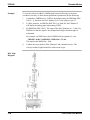
The figure below gives key dimensions for use in physically mounting the product.
When mounting multiple drives in a row, some customers have found the stiffness
of the drive and their mounting panel to be too low. To increase the mounted
mechanical integrity, connect to the threaded insert on the top front edge.
Mounting
Dimensions
PCE830/40 User Manual
1-5
Mounting and Installation
Danaher Motion
1.1.2. Connecting to AC Power
The PCE830/40 is designed to operate on balanced, three-phase mains from
380VAC to 480VAC. To insure compatibility with CE safety standard
EN50178, the mains phase voltage to neutral (PE) must remain within certain
limits. Compatibility of the PCE800-series with the major types of three-phase
mains is outlined below:
1-6
●
380/400/480 WYE with Earthed Neutral Mains (TB1-4, 5, 6)
This is the preferred mains for the PCE830/40 and insures that CE safety
standard EN50178 is met. An earthed neutral forces the phase voltages to
remain balanced with respect to neutral (PE), even if loads are unbalanced.
The phase to PE voltage of balanced mains measures about 57.7% of the
line-line voltage, so 380/400/480VRMS mains measures 220/231/277VRMS
nominal, meeting the EN50178 requirement for the PCE800-series of
300VRMS max.
●
380/400/480 Delta or WYE Unearthed Mains (TB1-4, 5, 6)
Phase to neutral (PE) voltages of unearthed WYE or delta mains often
measure balanced and below the 300VRMS requirement of EN50178.
However, the lack of neutral point earthing means the balance is not as
well maintained as with an earthed neutral. Pacific Scientific is unable to
ensure the unearthed 380/400/480VAC mains are compatible with CE
safety standard EN50178. You are advised to consult your CE safety
engineer about unearthed mains. For reference, the PCE830/40 human
safety barrier internal spacings are 5.5mm.
●
380/400/480 Delta or WYE Earthed, Unbalanced Mains (TB1-4, 5, 6)
Some three-phase mains are earthed in an unbalanced manner. One
example is a delta or WYE with one phase voltage earthed. 480VAC
mains of this type measure phase to PE: 480VAC, 480VAC, and 0VAC.
Another example is a delta mains with the mid-point of one delta leg
earthed: 480VAC mains of this type measure phase to PE: 240VAC,
240VAC, and 416VAC. Since the phase-to-PE voltage of these mains
exceeds the EN50178 design limit for PCE830/40 creepages and
clearances, the PCE800-series is not rated for operation on these mains.
PCE830/40 User Manual
Danaher Motion
Control Power
Mounting and Installation
The control power ( TB1-1, 2) is typically single-phase 115VAC to 240VAC
referenced to neutral (PE).
The control power is input to a switching power supply. The input (TB1-1 to
TB1-2) will accept voltages ranging from 85VAC to 265VAC or 120VDC to
375VDC.
To meet safety standard EN50178, the voltage from control voltage inputs
(TB1-1,2) to PE (TB1-3) must be less than 300V RMS.
●
Obtaining control power from the high voltage, three-phase AC bus
power mains
- Method 1: Stepdown Transformer (380/400/480VAC)
480VAC to 240VAC stepdown transformer, 25W to 50W connected
line-line from (380/400/480VAC) mains generates (190/200/240VAC)
suitable for the AC control power. Use of a line filter on the AC control
power input is recommended. For systems that must meet conducted
line noise regulatory requirements, a line filter on the AC control power
is required.
Method 2: No Transformer (380/400VAC ONLY)
Phase to neutral voltage of 380VAC and 400VAC mains is 220VAC
and 231VAC. The phase to neutral voltage of these mains is within the
range of the AC control supply and can be coupled through a line filter
to the AC control power inputs. Use of a line filter on the AC control
power input is REQUIRED when there is no transformer to block
mains spikes from the control supply.
A phase to neutral connection from 480VAC mains to AC control
power without a transformer is NOT possible. The phase to
neutral voltage for 480VAC mains is 277VAC, which is outside
the range of the AC control supply.
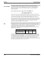
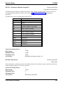
Fusing
Use high surge fuses in series with TB1 pins 4, 5, and 6.
Model
Fuse
PCE8x3 Bussman, KTK-20
PCE8x5 Bussman, KTK-30
AC control supply TB1 pins 1 and 2 is internally fused by a 1A, 250V fuse with
50A interrupt capability.
1.1.3. Connection to PE Ground
TB1-3 and chassis ground point must be connected to Protective Earth
ground (they are marked with the PE symbol). The connection at the
Protective Earth ground end must be hard wired (not utilize pluggable
connections)
A ground fault detector (RCD) cannot be depended on for safety.
PCE830/40 User Manual
1-7
Mounting and Installation
Danaher Motion
1.1.4. Grounding Shields for Safety and Low Emissions and
Susceptibility
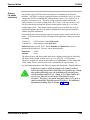
Dangerous voltages resulting from cable capacitance exist on some cable shields, if the
shields are not connected to PE ground.
If the motor power cable braid shield is exposed, it MUST be clamped to PE to
avoid a dangerous shock hazard.
Proper grounding of shields is also required to reduce radiated and conducted emissions as
well as to protect against susceptibility to external and self-generated noise. Follow these
shielding requirements carefully:
● The drive end of the motor cable shield must be connected to the PE or location on
the TB1 connector. The shield must also be clamped to the ground plane (described
above). If cable with a separate inner foil shield and outer braided shield is used
(Pacific Scientific CE cables for example), connect the foil shield to the PE or
location on the TB1 connector and clamp the outer braided shield to the ground plane.
If the leads for a motor holding brake are run with the motor leads, the holding brake
leads must be separately shielded and the shield connected to the PE or location on
the TB1 connector.
● The resolver cable should have inner shields around each twisted pair as well as an
overall outer braided shield. The inner shields are connected to J3 pin 5 while the outer
shield are clamped to the ground plane.
● The control leads to the J2 connector should have an outer braided shield with the
shield terminated through a conductive shell or clamped to the ground plane.
● When using an external regen resistor, if regen cabling is accessible during normal
machine operation, regen resistor cable should be rated at 600VDC and shielded with
shield connected to PE.
1.1.5. Grounding the Motor Case
Insure that the motor’s case is connected to PE ground by connecting the fourth wire
TB1-10
in the motor cable to the motor case.
If the motor is not properly grounded, dangerous voltages can be present on the motor
case due to capacitive coupling between the motor windings and case.
1-8
PCE830/40 User Manual
Danaher Motion
Mounting and Installation
1.1.6. Long Motor Power Cables and Baluns
Pacific Scientific cables are recommended for use with PCE830/40 drives. The drives have
been tested and characterized using these cables. There are two risks in using non-Pacific
Scientific cables:
● Drive performance or reliability may be adversely affected. The motor cable
capacitance, characteristics impedance, and shield termination affect the switching loss
of the transistors in the inverter.
● The motor power cable insulation can degrade over time and may fail. A long cable
driven by a switching inverter has internal voltage pulses due to reflections up and down
the cable that can easily be twice the bus voltage. If the cable is not designed for this
type of operation, even though it has the correct voltage rating, it will not be reliable.
If a non-Pacific Scientific cable is used, observe the following guidelines:
● Motor power cables should be "VFD" type. These cables are rated by the cable
manufacturer for Variable Frequency Drive operation.
● Motor power cables should be #14 AWG, 600V to 1,000V.
● Motor power cable shield and PE wire should be joined and connected to the PE
terminal of the drive.
PCE830/40 drives operated with Pacific Scientific PCE830/40 cables do not require a motor
cable balun for cables up to the maximum specified length (50m), but a motor cable balun is
RECOMMENDED when motor cable length exceeds 10m (32 ft.). The reasons for this
recommendation are:
Less Noise Coupling to Nearby Equipment
Motor cable baluns reduce the noise the drive can introduce into the machine grounding
resulting in an electrically quieter drive. When motor cable baluns are correctly applied
(i.e., they are sized for voltage and cable length such that they do not saturate),
substantial quieting is achieved.
Less Conducted Link Noise
Motor cable baluns lower conducted line noise by reducing the rise time of current
flowing in the motor cable shield. An external motor cable balun may be required to
meet CE when the motor cable is long.
Cooler Running Drive
Motor cable baluns used with long cables provide some reduction in transistor heating
and result in a cooler running drive. They lower the transistor switching loss by raising
the cable common mode impedance during the switching interval.
Pacific Scientific manufactures external motor cable baluns in different sizes and ratings.
New wide gap, high-energy baluns optimized for 480VAC drives like the PCE800 family are
in development. Contact the factory for assistance.
PCE830/40 User Manual
1-9
Mounting and Installation
1.2.
Danaher Motion
Safe Operation of the Drive
It is the machine builder’s responsibility to insure that the complete machine complies
with the Machine Directive (EN60204). The following requirements relate directly to
the servo controller:
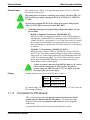
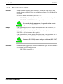
Prevent
Damage to
the Drive
Follow these guidelines to prevent damage to the servo drive during operation:
● Never plug or unplug connectors with power applied.
● Never connect or disconnect any wires to terminals with power applied
● Never plug or unplug an option card with control power applied
● If the drive indicates a fault condition, find the cause of the fault and fix it prior to
resetting the fault or power-cycling the drive.
Emergency
Stop
If personal injury can result from motor motion, the user must provide an external,
hardwired emergency stop circuit outside the drive. This circuit must simultaneously
remove power from the drive’s motor power terminal TB1-11, TB1-12, and TB1-13
and disable the drive (by disconnecting J2 pin 37 from I/O RTN).
The motor coasts under this condition with no braking torque.
If breaking torque is required to quickly stop the motor, a dynamic brake can be added
that loads the motor’s windings resistively. The motor should not be loaded until the
servo drive is disabled.
The holding brake (optional on Pacific Scientific motors) is NOT intended
to stop a spinning motor. It is designed to prevent a stopped motor from
rotating due to an applied torque
Avoiding
Unexpected
Motion
Always remove power from TB1 before working on the machine or working anywhere
machine motion can cause injury.
Avoiding
Electrical
Shock
Never power the servo drive with the cover removed or with anything attached to
circuitry inside the cover.
If the drive must be removed from the cabinet, wait at least five minutes after turning
off power before removing any cables from the drive or removing the drive from the
mounting panel.
Never connect or disconnect any wiring to the drive while power is applied. Always
power down and wait five minutes before connecting or disconnecting any wires to the
terminals.
Avoiding
Burns
The temperature of the drive’s heat sink and housing as well as external regen resistor
can be as high as 70°C (158°F). There is a danger of severe burns if these regions are
touched.
1-10
PCE830/40 User Manual
Danaher Motion
PCE830
2. PCE830
2.1.
800Tools
This section provides a step-by-step introduction to setting up the PCE830. This procedure uses the
minimum possible equipment to run an unloaded motor and set motor speed from a PC’s serial port. It
is strongly recommended that all first time users go through this procedure to become familiar with the
PCE830 and the PC interface software before installing the servo system in a machine.
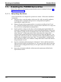
2.1.1. Installing 800Tools
Procedure
To install 800Tools:
1. Insert the 800Tools Installation disk in your CD-ROM drive (D:). From the
Windows95 or NT Start menu, select Run. At the Command Line, type
D:\setup.exe and click OK.
2. The install wizard will guide you through the installation.
When finished, the 800Tools disk should be removed from the PC and
stored in a safe place.
2.1.2. Starting 800Tools
Procedure
To begin using 800Tools, select Start|Program Files|Pacific Scientific|800Tools or
double click on the icon and the following window appears:
PCE830/40 User Manual
2-1
PCE830
Danaher Motion
800Tools
Main Menu
2.1.3. Getting Around in 800Tools
800Tools is a standard Windows application and the normal cursor movement keys operate the same
way as in all windows applications.
●
<F1> gives context sensitive on-line help
2-2
PCE830/40 User Manual
Danaher Motion
PCE830
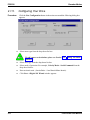
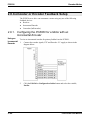
2.1.4. Configuring Your System
Applying AC
Power
Carefully check all wiring connections and ensure that J2-37 is not connected to
J2-40. Apply AC power to your controller.
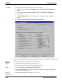
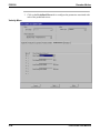
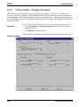
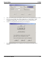
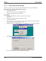
Serial Port
To specify the PC serial port that is connected to the PCE830:
1. Select Communication|Port/Axis and the following dialogue box appears:
2. Specify the serial port that a drive is connected with and the axis address of the
drive. If you do not know the axis address, choose Automatic Detected.
3. To verify your settings, click Test.
PCE830/40 User Manual
2-3
PCE830
Danaher Motion
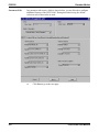
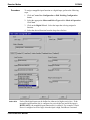
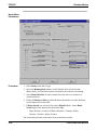
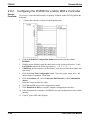
2.1.5.
Configuring Your Drive
Procedure
●
Click the New Configuration button in the main screen and the following dialog box
appears:
Select motor type from the drop down list box.
To add a motor to the database please see Section 2.1.9, “Editing The Motor
Database.”
2-4
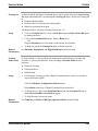
●
Select drive type from the drop down list box.
●
Select mode of operation. For example, Velocity Mode - Serial Command from the
drop down list box.
●
Enter an inertia ratio. (Inertia Ratio = Load Inertia/Motor Inertia).
●
Click Next. A Digital I/O Wizard window appears.
PCE830/40 User Manual
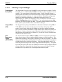
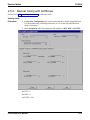
Danaher Motion
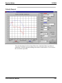
Digital
I/O Setting
PCE830
This wizard reminders you to set up the digital input and output. When the page
pops up, it shows default setting.
You can make your choice depended on your hardware connection.
Clicking Default brings back the default settings. Click Clear to clear all
selections.
After selecting I/O, click Next to go to the Parameter Edit Screen.
PCE830/40 User Manual
2-5
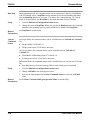
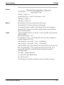
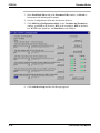
PCE830
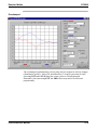
Parameter Edit
Danaher Motion
In a parameter edit screen, which is shown below, you are allowed to configure
additional features of the PCE830/40. During this initial set up, the default
values on each of these tabs are used.
●
2-6
Click Next to go to the next page.
PCE830/40 User Manual
Danaher Motion
PCE830
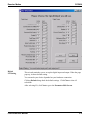
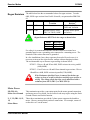
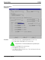
Print Parameters
•
Click Print to print all parameters in the Edit Parameter screen.
Save Parameters
to Disk
•
Click Save To File to save all parameters in the Edit Parameter screen to a
configuration file on PC disk.
Download To
Drive
•
Click Download To Drive to download the all parameters that were edited in
Edit Parameter screen to the drive.
Pacific Scientific recommends that you save the configuration to a file as a
backup.
Changing values on the Parameter Edit Window only affects the PC RAM copy.
You must download them to the drive to take affect.
800Tools sets the drive variable Enable to 0 at the beginning of the download.
To enable the drive you can use the Variables screen to set Enable = 1. If the
downloaded parameters were NVSaved, turning control AC power OFF and
then ON again will also return Enable to its default value of 1.
PCE830/40 User Manual
2-7
PCE830
NVSave to Drive
Danaher Motion
To save the configuration to the drive’s non-volatile memory:
● Click Yes to save to the drive's non-volatile memory.
Verify Setup
● Click Finish.
To verify that the set up procedure worked, turn the control AC power OFF and
then ON again. The Power LED should be BLINKING. If both LEDs are still
blinking, repeat the set up procedure.
The PCE830 is configured as a serial port commanded controller. The current
loop is properly compensated for the selected motor and the servo parameters
have been setup to give medium response (approximately 75 Hz velocity loop
bandwidth) with the unloaded motor. Additional default settings have also been
made.
Enable the Drive
The controller can be enabled at this time by closing the switch between the
Enable input (J2-37) and +24VDC (J2-40). Once enabled, the Power LED
should be ON. The commanded motor speed will be the power up default, set to
0 during configuration. Because the parameters were saved in non-volatile
memory, the controller can now be power cycled and, after power-up, be ready
to run with the parameters established during this session.
Before proceeding, the motor should be attached or temporarily clamped to
the table or bench. The inertial forces created during speed steps may make
the motor hop around.
2-8
PCE830/40 User Manual
Danaher Motion
PCE830
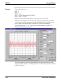
2.1.6. Changing Variables On-Line
Changing Motor
Velocity
Click Edit Drive Configuration On-Line to activate the variables window.
Getting Help
Context sensitive help is also available in the Parameter Edit window. Press
<F1> to get help information about a highlighted variable. Information about
all variables is available in this way.
Select VelCmd from the Variable dropdown list box. The current value of
VelCmd is displayed.
PCE830/40 User Manual
2-9
PCE830
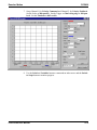
Changing A
Variable
Danaher Motion
To change the value of a VelCmd, click Change and the following window
appears:
●
Type in a new value.
●
Click OK to send the new value to the drive and return to the On-Line
Drive Configuration window.
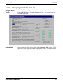
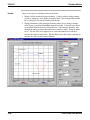
2.1.7. Uploading Parameters from the PCE830
Click Upload in the main screen to upload the current parameter values in the drive’s RAM to the
Parameter Edit screen. You can browse and modify them in this screen. Afterward, you can click Next
to go to the next pages to Save A File, Download To Drive or Print out. See Section 2.1.5, Configuring
Your Drive.
2.1.8. Edit a Configuration File
Click Edit File in the main screen. Select the file you would like to open from the list of files displayed.
The parameters in the file are loaded in the Edit Parameter screen. You can browse and modify them in
this screen. Afterward, you can click Next to go to the next pages to Save A File, Download To Drive
or Print out. See Section 2.1.5, Configuring Your Drive.
2-10
PCE830/40 User Manual
Danaher Motion
PCE830
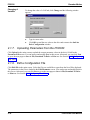
2.1.9. Editing The Motor Database
Add A Motor
To edit the motor database:
1. Select Utilities | Edit Motor Database.
2. Click New Motor to add a motor to the database. The following window
appears:
3.
4.
5.
6.
7.
Enter in a name for the motor. For example, MYMOTOR.
Select either Rotary or Linear as the Motor Type.
Select either English or Metric as the units.
Click OK.
Enter the motor parameters in the Motor Database Editor screen.
8.
Click OK. This motor appears in the motor list of Creating New
Configuration. See Section 2.1.5, Configuring Your Drive.
PCE830/40 User Manual
2-11
PCE830
Danaher Motion
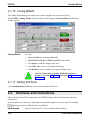
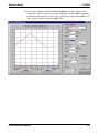
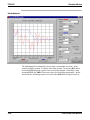
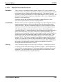
2.1.10. Tuning Wizard
The Tuning Wizard helps you to tuning your system. It applies only to the velocity loop.
Select Utilities | Tuning Wizard in the main menu. After inputting the Inertia Ratio, the following
window appears.
Tuning Wizard
You can:
•
Adjust the slider bar to change Bandwidth
•
Inertia Ratio, KVP, KVI, ARF0 and ARF1 can be altered.
•
Click Apply to send the changes to the drive.
•
Click Undo All to recover all variables in this page.
•
Click Default to set all variables in this page to default value.
For more information on Inertia, Bandwidth and Phase
Margin, see Section 2.5, Tuning and Section 2.7, Servo Loop
Parameters.
2.1.11. Exiting 800Tools
Click Communication | Exit in the main menu to terminate 800Tools.
2.2.
Interfaces and Connections
This section describes all the connections to the PCE830 and provides the information required to
interface to it.
In the list below, an overbar on a signal name means that the signal is active low logic. For example,
indicates the drive is faulted when it is pulled low.
Earth Ground
2-12
Chassis Ground, M4 x 12 screw with flat and lock washer.
PCE830/40 User Manual
Danaher Motion
PCE830
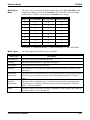
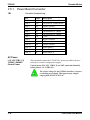
2.2.1. Power Board Connector
TB1
13 Position Terminal Strip
Pin
TB1-1
TB1-2
TB1-3
TB1-4
TB1-5
TB1-6
TB1-7
TB1-8
TB1-9
TB1-10
TB1-11
TB1-12
TB1-13
Label
L1C
L2C
PE
L1
L2
L3
+B
R
-B
PE
U
V
W
Description
120/240VAC Control Power
120/240VAC Control Power
Chassis Ground
380/400/480VAC (Input)
380/400/480VAC (Input)
380/400/480VAC (Input)
+ Bus
Regen Transistor
- Bus
Chassis Ground
Motor Phase U
Motor Phase V
Motor Phase W
AC Power
L1C, L2C (TB1-1, 2)
120VAC / 240VAC
Control Power
These terminals connect the 120/240 VAC power provided by the user to the
drive’s control voltage power supply.
Control power L1C, L2C (TB1-1,2) are NOT connected internally to bus
power L1, L2 (TB1-4,5).
The control voltage for the PCE830 controllers is input to a
switching power supply. This input accepts voltages ranging
from 85VAC to 265VAC.
PCE830/40 User Manual
2-13
PCE830
Danaher Motion
Chassis Ground
PE (TB1-3)
Convenience connector point for the user to connect the drive’s control
power and bus power to protective earth ground. This pin is directly
connected to the chassis and thus to the Chassis Ground Stud. Local
electrical code may require using the Earth Ground Chassis stud for this
function.
L1, L2, L3 (TB1-4, 5, 6)
380VAC/400VAC/480VAC
These terminals connect the balanced, three-phase 380/400/480 VAC
power provided by the user to the drive’s power output stage bus to
drive the motor.
380/400/480 VAC three-phase mains MUST be WYE type with
earthed neutral for PCE830 to be compatible with CE safety standard
EN50178. Earthed neutral WYE-type mains are strongly recommended
for all installations.
Single-phase or lower voltage operation is possible for
short periods of time to support installation or testing.
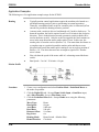
Regeneration Interface
+B, R, -B (TB1-7, 8, 9)
+Bus, Regen Resistor, - Bus
These terminals provide the connection points for a resistor to absorb
regenerated energy from the motor. A regeneration resistor goes from
+B to R. In the PCE833, if a regeneration resistor is not needed, (see
Appendix E), +B and R are open. In the PCE835, an internal regen
resistor is factory-wired to +B and R. -Bus (-B) on TB1-9 is usually
left open.
High Voltage! During normal operation +B, R, and -B
operate at the bus power voltages. The PCE830 regen
operates at about 800VDC. These are dangerous
voltages.
2-14
PCE830/40 User Manual
Danaher Motion
PCE830
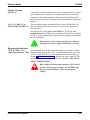
Regen Resistors The table below lists the recommended values for regen resistors. To order
66Ω, 200W regen resistor from Pacific Scientific, use part number PRK-20066.
Model
Resistance
PCE833 66Ω
PCE835 33Ω
Regen Resistor
Location
External
Internal (factory-wired
TB1-7 to TB1-8) 100W
External Regen
Resistor
66Ω, ±10%, 200W,
1500V min. isolation
External 400W option
(see below)
Regen Resistance MUST be in the range as shown below.
Model
PC833
PC835
Resistance
60 Ω to 72 Ω
30 Ω to 36 Ω
For safety it is recommended that the external resistor be mounted on a
grounded panel or use a grounding wire connected to a mounting screw. The
terminals of the resistor must not be grounded.
In a few installations, heavy duty regen may be needed. In such cases, it is
necessary to increase the regen resistor wattage without changing its ohms.
The recommended way to increase regen wattage is shown below:
PCE833 – Wire to +B and R four 66Ω, 200W resistors in series, parallel
(66Ω, 800W).
PCE835 – Cut off wires to +B and R from internal regen resistor. Wire to
+B and R two 66Ω, 200W resistors in parallel (33Ω, 400W).
Wait 10 minutes after Bus Power is removed for the bus cap
voltage to decay to a safe level before touching regen resistor or
wiring. The voltage on the bus caps can be monitored with a
voltmeter from +BUS (TB1-7) to -BUS (TB1-9).
Motor Power
PE (TB1-10)
Motor Case Ground
This termination provides a convenient point for the motor ground connection
and motor power wire shield. Local electrical code may require using the Earth
Ground Chassis stud for this function.
U, V, W (TB1-11, 12,
13)
Motor Phase
These three terminations provide the 3-phase power output to the brushless
motor. Observe motor polarity on these connections. For example, connect U
on the drive to U on the motor.
PCE830/40 User Manual
2-15
PCE830
Danaher Motion
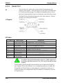
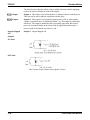
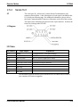
2.2.2. Serial Port
J1
The serial port (J1), utilizes the 9 contact female D subminiature style
connector shown below. A brief description of each signal is included in the
J1 I/O table on following page. For additional information, please refer to
the Serial Communications Transceiver Schematic at the end of this section.
The figureS below illustrates the pin-out for the 9-pin connector. It shows
the front view looking at the PCE830.
J1 Diagram
I/O Table
Pin Number
J1-1
J1-2
J1-3
J1-4
J1-5
J1-6
J1-7
J1-8
J1-9
Input/Output
Explanation
+5VDC RTN/ Shield
RS-232 TXD
RS-232 RXD
+5VDC
I/O RTN/+5VDC RTN
RS-485 TXD (+)
RS-485 TXD (-)
RS-485 RXD (+)
RS-485 RXD (-)
Common/shield - serial port interface
RS-232 transmitter output (from PCE830)
RS-232 receiver input (to PCE830)
+5VDC output (250 mA maximum between J1-4 and J1-5)
Common serial port interface
RS-485 transmitter output (from PCE830)
RS-485 receiver input (to PCE830)
An adapter can be powered from the serial port +5VDC output on J14 as long as the load current on J1-4, J2-14, and J3-10 total less than
250 mA.
The information provided in this section should be used to connect the PCE830 to
your computer for use with 800Tools. Two communication links are available, RS232 and RS-485. RS-485 allows a single computer to communicate with up to 32
PCE830s in multi-axis configurations. 800Tools defaults to communicate with axis
255 upon start up.
2-16
PCE830/40 User Manual
Danaher Motion
PCE830
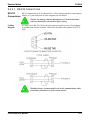
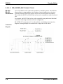
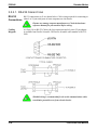
2.2.2.1. RS-232 CONNECTIONS
RS-232 connections on J1 are shown below. Cable wiring required for connecting to
RS-232
Connections either 9 or 25 pin serial ports of most computers are also shown.
Pinouts vary among computer manufacturers. Check the hardware
reference manual for your machine before wiring.
Cabling
Diagram
A 6-foot (1.8 m) RS-232 Cable with 9 pin connectors and a 9 pin to 25-pin adapter
is available from Pacific Scientific. The Pacific Scientific order number is RS-2325600.
Shielded wiring is recommended for the serial communications cable
to minimize potential errors from electrical noise.
PCE830/40 User Manual
2-17
PCE830
Danaher Motion
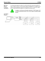
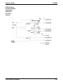
2.2.2.2. RS-485/RS-422 CONNECTIONS
RS-485 /
RS-422
Connections
Up to 32 PCE830s can be connected in parallel to a multidrop master. The PCE830s
must each have a unique address, set in software. Once the address is set, the Axis
Selection function in 800Tools must be used to select the designated axis address.
Then, either the RS-232 or RS-485 link can be used to communicate with the selected
axis.
For example, the RS-232 link can be used to completely setup and test an individual
axis before connecting it into the multi-axis configuration.
RS-485/RS-422 connections to J1 are shown below. A multidrop interconnection
diagram, showing multiple axes connected to a single host is also shown.
Connection
Diagram
2-18
PCE830/40 User Manual
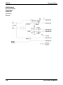
Danaher Motion
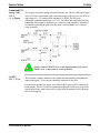
RS-232 to
RS-485
Converter
Installation
PCE830
It is often convenient to use an RS-232 to RS-485/RS-422 converter so an RS-232
port (available on all PCs) can be used to connect to multiple axes. The figure below
shows a typical installation, using the B & B Model 422 RS-232 to RS-422 adapter.
RS-232 to RS-485/RS-422 adapters are available from many sources.
An adapter can be powered from the serial port +5 VDC output on J14 as long as the load current on J1-4, J2-14, and J3-10 total less than
250 mA.
Installation
Diagram
PCE830/40 User Manual
2-19
PCE830
Danaher Motion
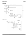
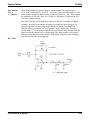
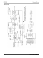
PCE830 Serial
Communications
Transceiver
Schematic
Installation
Diagram
2-20
PCE830/40 User Manual
Danaher Motion
PCE830
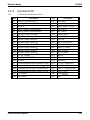
2.2.3. Command I/O
44 Position D subminiature female
J2
Pin
Description
J2-1
J2-2
J2-3
J2-4
J2-5
J2-6
J2-7
J2-8
J2-9
J2-10
J2-11
J2-12
J2-13
J2-14
J2-15
J2-16
J2-17
J2-18
J2-19
J2-20
J2-21
J2-22
Analog Command Input (+)
Analog Command Input (-)
I/O RTN
Analog Output1 (DACMonitor1)
Analog Output2 (DACMonitor2)
Analog Current Limit Input
I/O RTN
Encoder Output Channel A
Encoder Output Channel
Encoder Output Channel B
Encoder Output Channel
Encoder Output Channel Z
Encoder Output Channel
+5VDC (Output)
I/O RTN/ +5VDC RTN
I/O RTN
Command Encoder Input Channel A (Step)
Command Encoder Input Channel (Step)
Command Encoder Input Channel B (Dir)
Command Encoder Input Channel (Dir)
No Connect
No Connect
PCE830/40 User Manual
Pin
J2-23
J2-24
J2-25
J2-26
J2-27
J2-28
J2-29
J2-30
J2-31
J2-32
J2-33
J2-34
J2-35
J2-36
J2-37
J2-38
J2-39
J2-40
J2-41
J2-42
J2-43
J2-44
Description
No Connect
Relay Output (+) (Out4)
Relay Output (-) (Out4)
No Connect
No Connect
Analog Input 2
Analog Input 3
I/O RTN
Input 1 (Fault Reset)
Input 2 (CwInh)
Input 3 (CcwInh)
Input 4 (Reg1)
Input 5 (Reg2)
Input 6
Enable Input
Input RTN
+24VDC Output RTN
+24VDC (Output)
Out1, 2, 3 Supply (Input)
Out1 (
)
Out2 (
)
Out3
2-21
PCE830
J2 Diagram
2-22
Danaher Motion
The figure below illustrates the pin-out for the 44-pin connector. It shows the front
view looking at the PCE830.
PCE830/40 User Manual
Danaher Motion
PCE830
Command I/O
Analog CMD
J2-1, 2
(+), (-) Inputs
These inputs accept the analog command from the user. This is a differential input
to an A/D. It has a maximum single ended input range with respect to I/O RTN on
either input of ± 21V and an input impedance of 50 kΩ. The full-scale
differential command input range is ± 13.5V. The offset and single pole low pass
bandwidth of this signal is adjustable via a software setup parameter. When used
as a motion command the gain from this input is also adjustable via a software
setup parameter.
Always connect I/O RTN (J2-3) to the signal ground of the source.
Failure to do so may result in erratic operation.
I/O RTN
J2-3, 7, 15, 16
This terminal is signal common for the analog and non-optically isolated digital
inputs and outputs. These pins are internally connected in the drive.
For protection against line surges, one of the I/O RTN pins must be connected to
Earth ground. Pacific Scientific recommends making this connection at an earth
ground point in the cabinet reserved for single point grounding of all I/O Returns
(drives and supplies).
PCE830/40 User Manual
2-23
PCE830
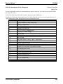
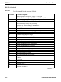
DAC Monitor
J2-4, 5
1, 2 Outputs
Danaher Motion
These analog outputs are general-purpose monitor points. The output range is
±5.5V with a resolution of 11V/65536 = 0.168 mV. The source impedance is 1 kΩ,
which yields a maximum short circuit to I/O RTN current of ± 5 mA. These outputs
are updated every 250 mS. There is a 2.5 kHz, 4.8 kHz and a 9.6 kHz analog Low
Pass Filter on these outputs.
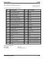
Each DAC Monitor can be mapped by software to be one of a number of internal
variables. The scale factor and the frequency of a single low pass filter pole are
software adjustable on each output by the DM1Gain, DM1F0 and DM2Gain,
DM2F0 software parameters for DAC Monitor 1 and 2 respectively. Variables
marked with a “*” are not range clamped and are allowed to wrap around when the
signal exceeds the output DAC’s voltage range. The other variables will clamp at
maximum when they exceed the analog voltage range. The table on the following
page lists the defined signal mappings.
DAC MON
2-24
PCE830/40 User Manual
Danaher Motion
PCE830
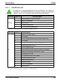
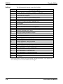
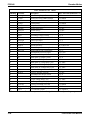
DAC Monitor List Table
DMxMap
Variable
Description
DAC Out Units (DMxGain = 1)
0
1
2
3
4
5
6
7
8
9
10
11
12
13
14
15
16
17
18
19
20
21
22
23
24
25
26
27
28
29
30
AnalogOutx
VelFB
VelCmdA
VelErr
FVelErr
Position
PosError
PosCommand
Icmd
IFB
AnalogIn
EncFreq
EncPos
ItFilt
HSTemp
Actual Analog Output Command
Measured Velocity (DM2 Default)
Actual Velocity Command (VelCmdA)
Velocity Error
Compensated Velocity Error
Measured Position*
Position Error*
Commanded Position*
Commanded Torque Current
Measured Torque Current (DM1 Default)
Filtered A/D Input
Encoder Frequency
Encoder Position*
Filtered Output Current Amplitude
Measured Heat Sink Temperature
Commutation Electrical Angle*
Motor Phase U Output Current
Motor Phase V Output Current
Motor Phase W Output Current
Motor Phase U Voltage Duty Cycle
Motor Phase V Voltage Duty Cycle
Motor Phase W Voltage Duty Cycle
Drive Bus Voltage
Resolver Absolute Position*
Commanded non-torque current
Measured non-torque current
Torque Voltage Duty Cycle
Non-torque Voltage Duty Cycle
Velocity Command (VelCmd)
Digital Command Frequency
I^2*t Filtered Current
V/V
1 V/kRPM
1 V/kRPM
1 V/kRPM
1 V/kRPM
1 V/Rev
1 V/Rev
1 V/Rev
1 V/A
1 V/A
1 V/V
1 V/Hz
10 V/4096 Cnts
1 V/100%
1 V/°C
1 V/Cycle
1 V/A
1 V/A
1 V/A
1 V/100%
1 V/100%
1 V/100%
1 V/V
1 V/Rev
1 V/A
1 V/A
1 V/100%
1 V/100%
1 V/kRPM
1 V/Hz
1 V/%Ipeak^2
IU
IV
IW
VBus
ResPos
VelCmd
DigitalCmdFreq
I^2*t
*These variables are allowed to wrap around when the signal exceeds the output voltage range.
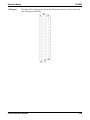
PCE830/40 User Manual
2-25
PCE830
Analog Current Limit
J2-6
Danaher Motion
This input limits the current flow to the motor when a voltage is applied
with respect to I/O RTN.
Outputs
J2-8, 9, 10, 11
CHAOUT
CH B Out
These two output pairs are differential TTL incremental position signals
generated by the Resolver feedback electronics. These outputs are
quadrature encoded to emulate an optical encoder. The resolution of these
signals, i.e. the emulated line count, is set by the EncOut parameter. These
outputs are buffered by 26LS31 type RS-422 compatible line drivers.
Maximum recommended load current is ± 20 mA, which corresponds to a
minimum line-to-line load resistance of 100 Ω. This drive capacity
corresponds to ten RS-422 compatible inputs such as the PCE830 encoder
inputs. These outputs are indefinitely short circuit proof to I/O RTN.
J2-12, 13
CH Z OUT
These two terminals function as a differential, TTL marker pulse. The
output pulse occurs once per motor shaft revolution starting at resolver
position = 0 and its width is approximately one quadrature encoder width.
This output comes from a 26LS31 type RS-422 compatible line driver.
Maximum recommended load current is ± 20 mA, which corresponds to a
minimum line-to-line load resistance of 100 Ω. This drive capacity
corresponds to ten RS-422 compatible inputs such as the PCE830 encoder
inputs. This output is indefinitely short circuit proof to I/O RTN.
J2-14, J2-15
+5VDC, I/O RTN/
+5VDC RTN
These two connections provide an auxiliary power supply for the user.
This output is 5VDC ±5% and is short circuit protected at 1 A nominal.
The maximum load limit for all connections to this supply is 250 mA.
The +5VDC RTN (J2-15) is connected to I/O RTN (J2-3, J2-7, J2-16, J230).
2-26
PCE830/40 User Manual
Danaher Motion
PCE830
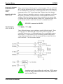
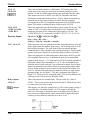
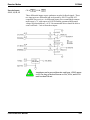
Encoder Inputs
CH A IN, CH IN, CH B IN, CH IN,
Step +, Step -, Dir +, Dir -,
Step Up +, Step Up -, Step Dn +, Step Dn -
J2-17, 18, 19, 20
These inputs are used as a quadrature encoder, step and direction, or up
and down count format incremental signal source. The decoding mode is
set by the EncMode parameter. The scale factor of this incremental
position command input is fully adjustable with software parameters. Full
decoding speed or more noise immune slow speed decoding is software
selectable.
These two input pairs are differential and are detected by 26LS32 type
RS-422 compatible line receivers. As differential inputs, the
recommended common mode range is < ±7V with respect to I/O RTN and
the guaranteed differential voltage logic thresholds are > ±0.2V.
Recommended drivers should be able to source and sink 3 mA to/from
these inputs. Each of these inputs has internal bias networks to allow easy
connection to single ended sources. When an input is open circuited it will
bias itself to between 2.2v and 2.5V, thus the remaining input pair
terminal will have a single ended guaranteed logic low for inputs < 2.0V
and a guaranteed logic high for inputs 2.7V. These levels are compatible
with a TTL driver combined with a pull up resistor. Pull up resistor should
be 470Ω.
Relay Outputs
J2-24, 25
These relay outputs are normally open. They are rated for 1 Amp at
30VDC. These relays may be opened/closed by Out4. When the drive
has no control power the relay is open.
PCE830/40 User Manual
2-27
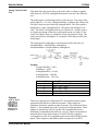
PCE830
Danaher Motion
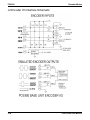
J2 Encoder I/O Interface Schematic
2-28
PCE830/40 User Manual
Danaher Motion
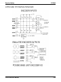
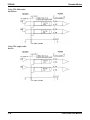
PCE830
Using TTL differential
line drivers
Using TTL single-ended
drivers
PCE830/40 User Manual
2-29
PCE830
Danaher Motion
Auxiliary Analog Inputs
J2-28, 29
Not Used.
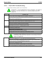
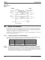
Inputs 1-6 J2-31, 32, 33,
34, 35, 36
These six optically isolated I/O connections are user programmable
discrete 24 V inputs. These inputs share a floating return (J2-38) with
the Enable Input (J2-37). A minimum drive capability of 4 mA is
required to fully power the opto. The user must supply 10V to 30V to
these inputs.
5 V inputs CANNOT be used.
Each of the inputs is set and read by software every 2 mSec. Each one
can be configured to be any of the available functions and the
configuration can be changed on the fly via digital communications.
Your default configuration is stored in the non-volatile memory. The
present state of each of these lines can be read via digital
communications. The logic polarity of these signals is also software
programmable. That is, an input can be defined to be active low or
active high. For edge triggered functions the active edge is
programmable.
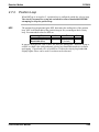
2-30
Logic State
InpX with respect to Input RTN
Low
0V to +2V
Undefined
+2V to + 10V
High
+10V to + 30V
PCE830/40 User Manual
Danaher Motion
PCE830
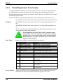
The list below describes the subset of the available functions and the mappings used as
the factory defaults for each of the inputs.
Fault Reset
Input
Input 1: This input is used to reset the amplifier following a fault. This input is
programmed active high so that an open circuited input does not activate the function.
During Fault Reset active the output stage is disabled and the reset condition will be
held in hardware for approximately 0.1 sec after Fault Reset is returned inactive.
CwInh Input
Input 2: This input prevents further motion in the clockwise shaft motion direction.
This input is programmed active high so that an open circuited input does not activate
the function. If the shaft is already moving in the clockwise direction, then the motor
will decelerate to zero velocity with the maximum torque allowed by the user set
output current limits. This input will have no effect on motion in the counterclockwise
direction. This input is useful for a clockwise over travel limit switch.
CcwInh Input
Input 3: Analogous to the CwInh input, except that this input prevents
counterclockwise motion.
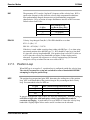
Reg1 Input
Input 4: This high speed input latches motor position within 50 µsec after a transition.
Reg2 Input
Input 5: Analogous to Reg1 input.
Input Mapped Input 6: Input Mapped Off
Off
Reg1 Input
J2-34
Probe inputs have a 50-µsec latch time.
PCE830/40 User Manual
2-31
PCE830
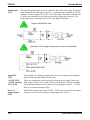
Enable Input
J2=37
Danaher Motion
This optically isolated input is used to enable the drive and is active high. The output
stage is disabled when this input is inactive. A minimum drive capability of 4 mA is
required. You must supply 10V to 30V to drive this input. This input is filtered with
a 1 mSec time constant low pass filter to prevent false triggering from noise. The
Enable input shares a floating return (J2-38) with Inputs 1 through 6.
5 V input CANNOT be used.
If the drive’s 24V supply is being used, connect as shown below.
2-32
PCE830/40 User Manual
Danaher Motion
PCE830
Input RTN
J2-38
This terminal is the floating common return for the six optically isolated digital
inputs and the optically isolated Enable input.
+24 VDC RTN,
+24 VDC (Output)
J2-39, J2-40
These two connections provide an auxiliary floating power supply for the user.
This output is 24VDC ± 10 % and is short circuit protected at 100 mA nominal.
The maximum load limit for all connections to this supply is 80 mA. + 24VDC
RTN is not connected to Input RTN.
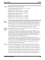
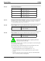
Out1, 2, 3
Supply (Input)
J2-41
The PCE830 requires an external 12VDC - 24VDC power source for the outputs.
This power source must be capable of supplying at least 150 mA.
Outputs
J2-42, 43, 44
These optically isolated outputs are current sourcing at 0 to 50 mA maximum.
External output supply should be limited to 30V. These outputs are short circuit
protected. Current folds back to about 25 mA during a short circuit. The external
output supply (J2-41) is shared by the three outputs.
VON
1.9V at 25 mA
2.25V at 50 mA
IOFF
5 µA
Response time
1 msec
Clamp voltage
40V (nominal)
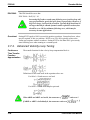
Each of the outputs is set and written to by software every 2 mSec. Each one can
be configured to be any of the available functions and the configuration can be
changed on the fly via digital communications. The user’s default configuration is
stored in the non-volatile memory. The present state of commanded outputs can
be read via digital communications. The logic polarity of these signals is also
software programmable. That is, an output can be defined to be active low or
active high. For edge triggered functions the active edge is programmable.
PCE830/40 User Manual
2-33
PCE830
Danaher Motion
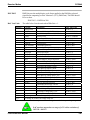
The list below describes the subset of the available functions and the mappings
used as the factory defaults for each of the outputs.
Output
Output
Output Mapped
Off
Output 1: This output is low when the drive is faulted or has no control power.
This line can be used to indicate a problem with the drive.
Output 2: This output is low when the control power is off, or when control
voltage is on and the drive is disabled (Enabled = 0). This output is pulled high
otherwise. This output is intended to drive a normally open relay that in turn
powers a mechanical brake on the motor shaft for applications that require a
positive shaft lock when the servo drive is off.
Output 3: Output Mapped Off
Outputs
ON State
OFF State
2-34
PCE830/40 User Manual
Danaher Motion
PCE830
Outputs Driving
Typical Loads
Output Schematic
PCE830/40 User Manual
2-35
PCE830
Danaher Motion
2.2.4. Base Servo Drive User I/O Connections
J3
FEEDBACK 15 Position D subminiature female
Pin
Description
1
RESOLVER S1 SIN + (Input) / Hall 1
2
RESOLVER S3 SIN - (Input) / Hall 2
3
RESOLVER S2 COS + (Input) / Hall 3
4
RESOLVER S4 COS - (Input)
5
SHIELD (I/O RTN)
6
RESOLVER R1 EXCITATION (Output)
7
RESOLVER R2 EXCITATION RTN (Output)
8
MOTOR PTC (Input)
9
MOTOR PTC RTN (Input)
10
+5VDC
11
I/O RTN
12
FEEDBACK ENCODER CHANNEL A (+)
13
FEEDBACK ENCODER CHANNEL A (-)
14
FEEDBACK ENCODER CHANNEL B (+)
15
FEEDBACK ENCODER CHANNEL B (-)
Feedback
Resolver
S1, S2, S3, S4 Inputs
J3-1, 2, 3, 4
These connections provide the inputs for the resolver’s sine/cosine outputs.
Differential inputs with 75Vµsec common mode impulse range and 25 kΩ
input impedance.
This only applies if a Resolver feedback device is being used.
Hall1, Hall2, Hall3
J3-1, 2, 3
These three single-ended hall channel sensor inputs are detected by +5VDC
CMOS compatible commutation signals with 60° spacing. These inputs are
each internally pulled-up to +5VDC via a 10 kΩ resistor. These input
signals are low pass filtered in hardware at 10 kHz.
This only applies if a Hall feedback sensor is being used.
2-36
PCE830/40 User Manual
Danaher Motion
Resolver R1 Excitation,
R2 Excitation RTN
Outputs
J3-6, 7
Motor PTC, PTC RTN
Inputs J3-8, 9
PCE830
These connections provide the resolver excitation output. 9.2V rms at 6510.42
Hz 75 mA rms maximum load. These outputs are fully short circuit protected
to I/O COMMON or to each other at room temperature (25°C), but at ambient
temperatures above 50°C, shorts longer than 5 minutes may cause damage.
These two inputs are intended to connect to a positive temperature coefficient
thermostat or normally closed thermostatic switch imbedded in the motor
windings. When the resistance between these terminals becomes greater than
6.2 kΩ the drive will fault and indicate a Motor Over Temperature fault. This
circuit directly interfaces with Pacific Scientific’s standard motor PTC.
PTC RTN is connected to I/O RTN.
Encoder Inputs
J3-12, 13, 14, 15
CH A,
, CH B,
These differential inputs expect quadrature encoder feedback signals. These
two input pairs are differential and are detected by 26LS32 type RS-422
compatible line receivers. As differential inputs, the recommended common
mode range is 7V with respect to I/O RTN and the guaranteed differential
voltage logic thresholds are ± 0.2V. Recommended drivers should be able to
source and sink > 3 mA to/from these inputs.
An adapter can be powered from the serial port +5VDC output
on J1-4 as long as the load current on J1-4, J2-14, and J3-10
total less than 250 mA.
PCE830/40 User Manual
2-37
PCE830
Danaher Motion
Using TTL
Differential Line
Drivers
2.3.
Mappable I/O Functions
The PCE830 has six user mappable inputs (J2-31 to J2-36), three user mappable outputs (J2-42 to J244), and one mappable relay output (J2-24, 25) which are available for users to interface to external
devices; proximity switch, PLC, LED.
Inputs Table
(InpMapX)
The following table lists the mappable input functions available for the Digital Inputs.
Mappable Input Function
Analog Input Null
Counterclockwise Inhibit
(default)
Clockwise Inhibit (default)
Command Gain Select
Enable 2
Fault Reset (default)
Gearing On
Home Switch Input
Move Select Bit 0, 1, 2
No Function
Position Mode Select
Run Stop
Start Move
Velocity Command Source
2-38
Description
Nulls the analog input by setting ADOffset to old ADOffset minus
AnalogIn
Inhibits motor motion in the counterclockwise direction when asserted
Inhibits motor motion in the clockwise direction when asserted
Switches the analog input scale factor between CmdGain and
CmdGain2
Second enable function
Resets drive faults
Turns electronic gearing on
Home switch input for a homing move
Determines the active move
Turns off mappable input functionality
Switches the active mode of operation to position mode
Selects between normal operation and setting the velocity command to
zero
Initiates the preset move as defined by the current state of the
MoveSelectBit inputs
Selects between VelCmd and VelCmd2
PCE830/40 User Manual
Danaher Motion
Procedure
PCE830
To assign a mappable input function to a digital input, perform the following
steps.
1. Click on Create New Configuration or Edit Exisiting Configuration
button.
2. Select the appropriate Motor and Drive Type and the Mode of Operation.
Click Next.
3. Click on the Digital I/O tab. Select the input that is being assigned a
function.
4. Select the desired function from the drop-down list-box.
Active hi/lo
Each of the digital inputs can be defined as either active high or active low. If the
mappable input function (bit) is configured as active high (low) and if the input is
HIGH (LOW), the mappable input function (bit) is asserted. For example, if Fault
Reset is configured as active high, when the input is high, Fault Reset is asserted.
PCE830/40 User Manual
2-39
PCE830
Analog Input
Null
Danaher Motion
In Analog Torque Mode or Analog Velocity Mode, the Command voltage can be nulled
to:
●
Reduce drift at zero volt command.
●
Set 50% analog offset for commanding bi-directional motion with a single
polarity adjustable voltage command source.
See AnalogIn and ADF0 in On-Line Help.
Related
Parameter(s)
Setup
1. Connect the Analog command source to J2-1 and J2-2.
2. Activate the input momentarily to offset the command for zero motion.
3. To reduce drift, command zero volts and remove small offsets with the null.
4. To set bi-directional motion with a single polarity input, convert a 0V to 10V analog
command to ±5V by commanding 5.0V on the analog input when you null the analog
input. Use Command Gain (CmdGain) to scale the input voltage for appropriate
output.
Command
Gain Select
In Torque Mode or Velocity Mode (except Serial Velocity), the command scale can be
switched between CmdGain value and CmdGain2 value for:
●
A Direction input that changes polarity of a jog command.
●
A complex motion input that changes speed.
●
An input to command zero motion.
Setup
1. Click the Edit Drive Configuration Online button.
2. Change the value of CmdGain2 to the desired value:
For Direction, set CmdGain2 = ( - CmdGain).
To Change speed, set CmdGain2 = NonZero value.
To hold zero command, set CmdGain2 = 0.
When you activate the Command Gain Select input, the command will switch from a
scale of Command Gain CmdGain to a scale of CmdGain2.
See CmdGain, CmdGain2, and BlkType(Operation Mode) in On-line Help.
Related
Parameter(s)
2-40
PCE830/40 User Manual
Danaher Motion
Gearing On
PCE830
In Position Mode, the Digital Command source can be turned on by activating Gearing
On input, and turned off by deactivating the Gearing On input. Deactivate Gearing On
to:
● Perform a Homing Move
● Perform a move to a flying shear start position
● Hold zero speed until next input
An Absolute Move will abort Gearing (Gearing On = 0)
Setup
1. Click on the Digital I/O tab. Setup a Start Move input and Move Select Bit inputs
for starting the move.
2. Click on the Predefined Moves tab. Setup a Home move.
OR
Setup an Absolute move to Position 0 or the known start position.
3. To hold zero speed the Gearing On input is all that is needed.
Related
Parameter(s)
See EncMode, DigitalCmd, and DigitalCmdFreq in in on-line Help.
Position
Mode Select
In Torque Mode or Velocity Mode, the mode can be switched between Torque and
Position, or Velocity and Position. After switching to Position Mode the drive
performs:
● Electronic Gearing
● Predefined Moves
● Hold Position
Setup
1. For Electronic Gearing, provide a Digital Command Source such as an encoder or
step and direction signals.
Click the Edit Drive Configuration OnLine button.
Set EncMode to the type of Digital Command Source provided.
2. To define moves, click on the Predefined Moves tab, and the Digital I/O tab to
define MoveSelectBits and StartMove inputs.
3. To Hold Position, activate the input.
Related
Parameter(s)
See CmdGain, VelCmd and BlkType(Operation Mode) in on-line Help.
PCE830/40 User Manual
2-41
PCE830
Danaher Motion
Run Stop
In any operating mode, the command source can be switched to 0 rpm for Clutch/Brake
with NO holding torque. StopTime sets the amount of time before disabling the motor
after the RunStop function is activated. This allows for a controlled stop. In Velocity
Mode or Position Mode, use DecelLmt to decelerate the motor before it disables.
Setup
1. Click the Edit Drive Configuration Online button.
2. Change the value of StopTime. When you activate the RunStop input, the command
switches from operating speed to 0 rpm, and the drive disables after StopTime.
See StopTime in on-line Help.
Related
Parameter(s)
Velocity
Command
Source
In Torque Mode, the command source can be switched between VelCmd and VelCmd2
for:
● Torque inhibit if VelCmd2 = 0.
● Torque preset select if VelCmd2 is non-zero.
In Velocity Mode, the command source can be switched between VelCmd and
VelCmd2 for:
● Clutch/Brake with holding torque if VelCmd2 = 0.
● Velocity preset select if VelCmd2 is non-zero.
In Position Mode, the command source can be switched between VelCmd and VelCmd2
for:
● Switching between electronic gearing follower and velocity preset command.
Setup
1. Click the Edit Drive Configuration OnLine button.
2. Change VelCmd2 to the desired preset value.
3. Activate the input mapped for Velocity Command Source to select the VelCmd2
value.
See VelCmd, VelCmd2, BlkType(Operation Mode) in on-line Help.
Related
Parameter(s)
2-42
PCE830/40 User Manual
Danaher Motion
Outputs Table
(OutMapX)
PCE830
The following table lists the mappable output functions available for the Digital and
Relay Outputs.
Mappable Output Function
Brake (default)
Electrical Revs
Enabled
Excess Position Error
Fault (default)
Mechanical Revs
Move Done
No Function
Zero Speed
Active hi/lo
Description
Indicates when the motor is not powered and a mechanical brake is
needed to hold the motor.
Square wave whose frequency is equal to the motor electrical
frequency.
Indicates whether power can flow to the motor.
Asserted when there is excess following error for an extended period
of time (following error limit is defined by PosErrorMax).
Indicates whether the drive has faulted and is disabled.
Square wave whose frequency is equal to the resolver’s electrical
frequency which is typically equal to the mechanical Rev/sec.
Indicates that a move is complete.
Turns off mappable output functionality.
Activated when the motor’s speed goes below the speed threshold set
by the parameter ZeroSpeedThresh.
Each of the digital outputs can be defined as either active high or active low. If the
mappable output function (bit) is configured as active HIGH (LOW), when the
function (bit) is asserted, the output is HIGH (LOW). For example, if Move Done is
configured as active high, when the move is complete, the output goes high.
PCE830/40 User Manual
2-43
PCE830
Procedure
Danaher Motion
To assign a mappable output function to a digital output:
1. Click either the Create New Configuration or Edit Exisiting Configuration
button.
2. Select the appropriate Motor and Drive Type and the Mode of Operation.
Click Next.
3. Click the Digital I/O tab. Select the output or relay that is being assigned a
function.
4. Select the desired function from the drop-down list-box.
Excess
Position
Error
In Position Mode, indicates synchronization failure for:
Setup
1. Click the Edit Drive Configuration OnLine button.
● Warning the master when out of synchronization
● Preventing a position error fault from disabling the drive
2. Change PosErrorMax to the appropriate Motor Counts as a trip threshold (Motor
Counts = 65536 counts/rev).
Related
Parameter(s)
2-44
See PosErrorMax, KPP, and KVFF in on-line Help.
PCE830/40 User Manual
Danaher Motion
PCE830
Move Done
When executing Predefined Moves, the Move Done output activates when the motor
feedback reaches the final move position. InPosLimit sets the window of motor counts
to determine if the motor is near final position. A smaller window (InPosLimit = 2)
provides more accurate results and takes longer to settle. Use the MoveDone output to
tell the master control that the drive is finished with the move and in final position.
Setup
1. Click the Edit Drive Configuration OnLine button.
2. Change InPosLimit to the appropriate Motor Counts as a trip threshold (Motor
Counts = 65536 counts/rev, 6 counts = 1/10000 rev).
Related
Parameter(s)
See InPosLimit in on-line Help.
Zero Speed
In any Operating Mode, the Zero Speed Output can be used to indicate:
● If the motor is near zero speed when ZeroSpeedThresh is near 0.
● If the motor is at speed when ZeroSpeedThresh is set near target speed.
Setup
1. Click the Edit Drive Configuration OnLine button.
2. Change ZeroSpeedThresh near but not past the desired target speed. There is
velocity ripple that can cause output bounce if the threshold is set too close to the
target.
Related
Parameter(s)
●
See ZeroSpeedThresh in on-line Help.
PCE830/40 User Manual
2-45
PCE830
Danaher Motion
Application Examples
The following are a few application example setups for the PCE830.
Homing
●
Typically motion control applications require the machine to be homed to a
predefined starting position, prior to performing its normal operations.
Generally, a mechanical home switch or a marker pulse is referenced (off an
encoder) to provide the homing reference position.
●
A motor (with a resolver) drives a load through a 0.5 inch/rev lead screw. To
home the machine, the load is required to move at 30 in/min in the clockwise
direction. This is in the direction toward a proximity switch (which will be
used as the home switch). After the switch is triggered, the load continues to
move in the same direction until a marker pulse is seen. In this case, the
marker pulse is from the resolver (ResPos = 0). The motor then decelerates to
a complete stop to a position beyond the marker pulse and then reverses
direction back toward the marker pulse coming to rest at resolver position of
ResPos = 10. The drive then activates an output to signal a PLC that the
move is done.
●
First calculate the speed of the motor while it’s advancing toward the home
switch:
●
Run Speed = 2 rev/in * 30 in/min = 60 rpm
Motion Profile
Procedure
2-46
1. Create a new configuration and select Position Mode - Predefined Moves as
the mode of operation.
2. Click the Digital I/O tab. Set up a Home Switch Input, a StartMove input,
and a MoveSelectBit. Set up a MoveDone output.
3. Click the Predefined Moves tab. Setup a Home move using the following
parameters:
Move Type:
Home
Run Speed:
60 rpm
Accel Rate:
1000 rpm
Decel Rate:
100 rpm
Distance Offset:
10 counts
Reg Select:
n/a
Homing Mode:
Home Switch + Marker Pulse
Home Direction: Clockwise
PCE830/40 User Manual
Danaher Motion
Clutch/Brake
PCE830
A thermal cut and seal machine uses an analog input signal to command a geared
motor (gear ratio 10:1) to spin a pinch roller that feeds material into the thermal
cutter and sealer. There is a 2.5 volt signal available to command speed. The roller
has a diameter of 3.82 inches and must advance roughly 24 inches of material in 1
second. A PLC provides an input to emulate a clutch/brake operation commanding
zero velocity and stopping motor motion. A second input from the PLC also reverts
the drive to maintain motor position during the cut and seal process. The cycle is
then repeated.
First calculate the required CmdGain to provide the necessary speed for the 1 second
move:
Roller Circumference =
p * Roller Diameter = p * 3.82 inch = 12 inch
Distance for motor to move =
10 * (24 inch move / 12 inch/rev) = 20 revs
Velocity = 20 rev/sec (1200 rpm) =
CmdGain (krpm/V) * AnalogIn (V)
CmdGain = 1.2 Krpm / 2.5V = 0.48 Krpm/V
Motion Profile
PCE830/40 User Manual
2-47
PCE830
Procedure
Danaher Motion
1. Create a new configuration and select Velocity Mode as the mode of operation.
2. Click the Digital I/O tab. Select Velocity Command Source as the function on
Input4 to switch between the sources of two unique velocity commands.
3. Select Position Mode Select as the function on Input5 to switch between
velocity and position modes of operation. This step is optional depending upon
whether your application can tolerate a small amount of drift when commanding
zero velocity as an analog input. When using this mode of operation during the
brake mode VelCmd is equal to zero.
4. Set VelCmd2 = zero. The direction of the velocity move will be controlled by
the polarity of the value entered.
5. Set AccelLmt and DecelLmt to the desired clutch activation acceleration and
brake activation deceleration respectively.
VelCmd is the velocity commanded through the analog input, encoder frequency
input, or the serial port depending upon the mode of operation selected. VelCmd2
is a stored value of velocity that can only be changed serially.
2-48
PCE830/40 User Manual
Danaher Motion
Gearing
(w/ phase
correction)
PCE830
An encoder with a 1024 line count is mounted to a continuous web embosser
machine. A PCE830 is setup as a position follower such that for every 1 rev of the
encoder the PCE830 commands the follower motor to move 1 rev (ratio of 1:1 in
encoder revs to motor revs). The drive will be required to phase advance the
follower motor ¼ rev when an input from a PLC occurs. Likewise, the drive will
also be required to decrement the follower motor (phase retard) by ¼ rev when
another input occurs. These phase advance/retard moves will allow the servo to
emboss the imprints into the web ahead or behind where they typically would be
without any phase adjustment.
First calculate the required gearing ratio between the master encoder and the slave
motor. A 1024 line count encoder will output 4096 quadrature counts per encoder
revolution.
1 motor rev = 65536 resolver counts (PulsesOut)
1 encoder rev = 4096 encoder counts (PulsesIn)
PulsesOut cannot exceed 32767. Divide PulsesIn and PulsesOut by four to
maintain the desired ratio. The new values should then be:
PulsesOut
PulsesIn
= 16384
= 1024
The phase advance and phase retard index move distances must also be calculated.
The motor must perform an index move of ¼ rev (65536/4 = 16384 counts).
Therefore, program two preset incremental moves of Distance =16384 counts and –
16384 counts. Phase correction moves are commanded on top of gearing. To
prevent backward motion of the follower, ensure that RunSpeed < DigitalCmdFreq.
It may be necessary to refine the tuning of the system in order to
reduce the steady state position following error (position lag). Steady
state position following error can be minimized by increasing the
velocity feedforward gain (Kvff). Setting Kvff to 100% reduces this
error to zero. However, at the expense of potential excessive
overshoot. Therefore, your system may require that Kvff be set to a
value less than 100% (typically around 70%-80%). For additional
information on tuning refer to Section 2.5, Tuning.
PCE830/40 User Manual
2-49
PCE830
Danaher Motion
Motion Profile
Procedure
1. Create a new configuration and select Position Mode – Electronic Gearing as
the mode of operation.
2. Set desired number of commanded motor Pulses Out per the number of encoder
Pulses In.
3. Click the Digital I/O tab. Select Gearing On as the function for the input to
initiate gearing.
4. Select Start Move as the function on the input used to initiate a preset
incremental move.
5. Click the Predefined Moves tab. Define an Incremental move for the phase
advance index move.
6. Create a second incremental move for the phase retard index move.
Registration
Moves
Registration marks can be used to perform preset registration moves based upon
activation of a registration input. Typically, these moves can be used to advance a
product a predefined distance after activation of a proximity sensor input. All
registration inputs must be tied to a dedicated registration input on either Input 4
(J2-34) or Input 5 (J2-35).
A conveyor processing material is being driven by a one inch diameter roller
(directly coupled to a motor) incrementing at a constant speed of 1000 rpm. There
are marks on the material spaced evenly every eight inches on the conveyor. These
marks are detected by a proximity sensor interfaced into Input 4 on the PCE830 as a
registration input. Once the sensor is activated, the motor advances the conveyor
one more inch before coming to a complete stop within 75 milliseconds. After the
motor has come to a complete stop, the drive activates an output signaling a nearby
PLC that the registration move is complete. The PLC initiates the cycle to repeat
itself.
2-50
PCE830/40 User Manual
Danaher Motion
Calculate
Move
Parameters
PCE830
First, calculate distance to move (Distance Offset) after sensing registration input:
Roller Circumference = π * Roller Diameter
= π * 1 inch = 3.1415 inch
Distance for motor to move = 1 inch move / 3.1415 inch/rev
= 0.31832 revs
Distance Offset = 0.31832 motor rev * 65536 counts/motor rev
= 20861 counts
Next, calculate the minimum deceleration rate necessary to ensure coming to a
complete stop within the 75 millisecond specification.
Decel Rate = 2 * 0.31832 revs * 60 / (0.075 seconds)2
= 6791 rpm/s
Finally, calculate the minimum distance the motor should move to ensure the
registration input is seen every cycle.
Distance = 8 inch * 0.31832 rev/inch * 65536 counts/rev
= 166892 counts
Motion Profile
PCE830/40 User Manual
2-51
PCE830
Procedure
2-52
Danaher Motion
1. Create a new configuration and select Position Mode - Predefined Moves as
mode of operation.
2. Click the Digital I/O tab. Select Start Move as the function on Input3 to initiate
a preset move.
3. Select Move Select Bit 0 as the function on Input4 to setup a preset move based
upon an external input.
4. Select Move Done as the function on Out3.
5. All registration moves must be tied to a dedicated registration input on either
Input 4 (J2-34) or Input 5 (J2-35). Select No Function for either Input 4 or
Input 5 on the Digital I/O tab.
6. Click the Predefined Moves tab. Setup an Incremental Registration move.
The registration move is the number of counts set in the Distance Offset
window. This move is activated by the user as active on the rising or falling
edge of this input.
Distance Offset:
20861 counts
Run Speed:
1000 rpm
Reg Select:
Reg 1 (Inp4)
Accel Rate:
10000 rpm/s
Reg 1 Active Edge: Rising Edge
Decel Rate:
10000 rpm/s (> min 6791 rpm/s)
Distance:
200000 counts (> min 166892 counts)
PCE830/40 User Manual
Danaher Motion
Jog Moves
PCE830
A motor is mechanically linked to a pulley (with a 1.91 inch diameter) which drives
a conveyor at 50 inch/sec. The motor rotates the pulley at a constant speed to feed
products past a scanning station. Occasionally, the drive will be required to run the
conveyor at two additional speeds (100 inch/sec and 25 inch/sec) to meet production
needs and running different products through the scanning station.
First calculate the required motor velocity(s) to advance the conveyor:
Pulley Circumference =
π * Pulley Diameter = π * 1.91 inch = 6 inch (1 motor rev)
Velocity1 =
(50 inch/sec) * (1 rev/6 inch) * (60 sec/min) = 500 rpm
Velocity2 =
(100nch/sec) * (1 rev/6 inch) * (60 sec/min) = 1000 rpm
Velocity3 =
(25 inch/sec) * (1 rev/6 inch) * (60 sec/min) = 250 rpm
VelCmd2 is a storable serial velocity command that will be used to set the speed for
Velocity1. Velocity2 and Velocity3 will obtained by use of the analog input on the
PCE830. Either the user can provide their own external analog signal OR make use
of the drives ability to produce an analog offset (using ADOffset). For this
example, ADOffset is set to 1 volt. This is used to calculate the appropriate scaling
factor to scale this analog signal into a speed reference.
Velocity2 = 1000 rpm =
CmdGain (krpm/V) * (AnalogIn (V) + ADOffset (V))
CmdGain = 1.0 krpm / 1.0 V = 1.0 krpm/V
Velocity3 = 250 rpm =
CmdGain2 (krpm/V) * (AnalogIn (V) + ADOffset (V))
CmdGain2 = 0.25 krpm / 1.0 V = 0.25 krpm/V
If an external analog signal is provided to vary the analog input, then
a wide range of jogging speeds are possible.
PCE830/40 User Manual
2-53
PCE830
Danaher Motion
Motion Profile
Procedure
1. Create a new configuration and select Velocity Mode — Analog Command as
the mode of operation.
2. Click the Digital I/O tab. Select Command Gain Select as the fucntion for the
input to be used to select scaling/polarity of incoming analog command signal.
3. Select Velocity Command Source as the function of the input to be used to set
serial velocity command.
4. Click the Velocity Controller tab. Set Offset Voltage as desired analog signal
command OR provide appropriate incoming external analog signal with the
appropriate voltage (the latter may be preferred as it permits variable speeds to
be achieved).
5. Click the Edit Drive Configuration Online button. Set CmdGain and
CmdGain2 to the desired values for scaling and polarity.
6. Set VelCmd2 to desired speed (a setting of 0 rpm represents a STOP input)
VelCmd2 is NOT tied to the analog input signal coming into the drive.
2-54
PCE830/40 User Manual
Danaher Motion
2.4.
PCE830
Selecting Modes of Operation
The PCE830 has three distinct modes of controlling the motor shaft and three distinct sources for the
shaft command:
Modes
●
●
●
Torque Control
Velocity Control
Position Control
Commands
●
●
●
Analog Command
Incremental Digital Pulse Command
Serial Port Command
Mode of Operation
Command Source
Position Mode - Predefined Moves
Digital Inputs
Position Mode - Step and Direction
Step and Direction
Position Mode - Electronic Gearing
External Encoder
Velocity Mode - Analog Command
Differential Analog Input
Velocity Mode - Frequency Command Frequency/Pulse
Velocity Mode - Serial Command
RS-232/RS-485
Torque Mode - Analog Command
Differential Analog Input
Torque Mode - Frequency Command
Frequency/Pulse
Each of the drive’s operating modes can be easily set up using Create New
Configuration or Edit Existing Configuration buttons of 800Tools. The following
sections give the details on these operating modes and their command source.
Refer to Section 2.7, Servo Loop Parameters for control block diagrams and
additional information on velocity and position loops.
PCE830/40 User Manual
2-55
PCE830
Danaher Motion
2.4.1. Position Mode - Predefined Moves
This mode allows the user to define up to 8 distinct moves. The predefined moves may be selected and
then triggered using the digital inputs on J2-31 through J2-36.
Procedure
1. Create a new configuration and select Position Mode - Predefined Moves as the
mode of operation.
2. Click the Digital I/O tab to define MoveSelectBits and a StartMove input.
Digital I/O Tab
2-56
PCE830/40 User Manual
Danaher Motion
Selecting a
Move
PCE830
The active move is selected based on the binary state of the MoveSelectBit(s) and
initiated by a change of state on the StartMove. The table below indicates which
predefined move will be activated upon a StartMove state change.
Move # MoveSelectBit2 MoveSelectBit1 MoveSelectBit0
0
0
0
0
1
0
0
1
2
0
1
0
3
0
1
1
4
1
0
0
5
1
0
1
6
1
1
0
7
1
1
1
ActiveMove = 4*(MoveSelectBit2) + 2*(MoveSelectBit1) +1*(MoveSelectBit0)
Move Types
The following table lists the move types available:
Move Type
Description
Hold Position
The motor aborts motion and holds position.
Velocity
The motor ramps up/down to a predefined runspeed.
Incremental
The motor travels a predefined distance.
Absolute
The motor travels to a predefined position relative to the home (0) position. (Turns
gearing off)
Incremental
Registration
The motor starts an incremental move. If a transition occurs on the registration input
before the move is complete, the motor moves to the latched position + Distance
Offset.
Absolute
Registration
The motor starts an absolute move. If a transition occurs on the registration input
before the move is complete, the motor moves to the latched position + Distance
Offset. (Turns gearing off)
Home
The motor searches for a home reference, establishes a home position, and returns to
the home position. (Turns gearing off)
PCE830/40 User Manual
2-57
PCE830
Danaher Motion
3. Click on the Predefined Moves tab to configure the parameters associated with
each of the predefined moves.
Velocity Move
2-58
PCE830/40 User Manual
Danaher Motion
PCE830
The homing functionality of the PCE830 allows the user to establish a home
position based on four different home references. The table below lists each of the
references used for homing, and describes how each establishes the home position.
Homing
Home reference
Description
Home Switch
Transition of Home Switch(Requires one of the Digital Inputs to be
mapped to the HomeSwitch function.)
Marker Pulse
Internal resolver marker pulse*
Home Switch + Marker Pulse Transition of Home Switch then marker pulse
Use Present Position
Current position is established as home position
*If using encoder feedback, the physical Z channel from the encoder is used as the
marker pulse. Select Reg1 (Inp4) if the encoder Z channel is to be connected to digital
Input4 or Reg2(Inp5) when connecting to digital Input5. Make sure the mapping for the
input used is set to No Function.
Marker Pulse
Using
Resolver
If using resolver feedback, all home moves to a marker pulse will be based on
resolver position equal to zero (ResPos = 0).
Marker Pulse
Using
Encoder
If using encoder feedback, all home moves to a marker pulse will be based off the
marker pulse output from the encoder. This channel must be physically wired to one
of the two dedicated registration inputs, Input 4 (J2-34) or Input 5 (J2-35). Select
this input using the Reg Select pull-down tab. The Active Edge (rising edge or
falling edge) must also be defined for the registration input.
PCE830/40 User Manual
2-59
PCE830
Danaher Motion
Home Move
Parameters
Procedure
1. Select Home as the Move Type.
2. Select the Homing Mode (Home Switch, Marker Pulse, Home Switch +
Marker Pulse, Use Present Position) to determine the reference for homing.
3. Select Home Direction of motor rotation for home move as clockwise or
counterclockwise.
4. Define the Distance Offset position the motor should move to after the home
switch input has been detected.
5. If Home Switch was selected, click on the Digital I/O tab. Select Home
Switch Input as the function for the desired input.
Home Position = Position of Home Reference + Distance Offset
Position = Position - Home Position
The motor then performs an absolute move to the home position.
2-60
PCE830/40 User Manual
Danaher Motion
PCE830
Registration Move
Parameters
Procedure
1. Select either Incremental or Absolute Registration as the Move Type.
2. Select Reg1 (Inp4) or Reg2 (Inp5) as the registration input.
Verify that there is No Function defined for the registration input.
3. Select the Active Edge for the registration input.
4. Set the Distance to the desired value.
5. Set the Distance Offset to the desired value. This is the distance that the motor
will travel upon registration.
PCE830/40 User Manual
2-61
PCE830
Danaher Motion
2.4.2. Position Mode - Step and Direction
This mode allows the PCE830 to be controlled by a stepper indexer feeding it with step and direction
signals on J2-17 through J2-20. Predefined moves are also available in this mode.
Procedure
1. Select Position Mode - Step and Direction from the Mode of Operation
dropdown list box.
2. Specify the number of steps per motor revolution. This number must be evenly
divisible by four. Divide this number by four and fill in Pulses In in the
Parameters Edit screen. For industry standard step sizes, select from the table
below.
Steps/Rev
2-62
Motor Mechanical Deg/Step
200 (Full)
1.8
400 (Half)
0.9
1000 (1/5)
0.36
2000 (1/10)
0.18
5000 (1/25)
0.072
25000 (1/125)
0.0144
50000 (1/250)
0.0072
PCE830/40 User Manual
Danaher Motion
PCE830
Step and Direction
PCE830/40 User Manual
2-63
PCE830
Danaher Motion
2.4.3. Position Mode - Electronic Gearing
This mode configures the PCE830 to follow external encoder signals applied to the encoder inputs on
J2-17 to J2-20. Predefined moves are also available in this mode.
Procedure
1. Select Position Mode - Electronic Gearing from the Mode of Operation
dropdown list box.
2. Enter the number of motor resolver counts (PulsesOut) (1/65536 of a rev) that
you want the motor to move for the specified number of input encoder
quadrature counts (PulsesIn).
Example
If the input encoder line count (PulsesIn) is 1024 (4096 quadrature counts per
encoder revolution) and the motor should make one revolution for every encoder
revolution, then:
1 rev = 65,536 resolver counts per
1 rev = 4096 encoder counts.
Because 65,536 is greater than the maximum value for PulsesOut, divide both
numbers by four. This results in 16,384 motor resolver counts for 1024 input
encoder counts.
2-64
PCE830/40 User Manual
Danaher Motion
PCE830
Electronic Gearing
PCE830/40 User Manual
2-65
PCE830
Danaher Motion
2.4.4. Velocity Mode - Analog Command
This mode allows the differential analog voltage between terminals J2-1 and J2-2 to set the motor’s shaft
velocity. The output shaft velocity per input volt is set by the CmdGain parameter in kRPM/V and
should be set by the user to the desired value.
Procedure
1. Select Velocity Mode - Analog Command from the Mode of Operation
dropdown list box.
2. Set CmdGain to the desired value.
Motor Velocity[kRPM] = AnalogIn[V]*CmdGain[kRPM/V]
Velocity Controller
2-66
PCE830/40 User Manual
Danaher Motion
PCE830
2.4.5. Velocity Mode - Frequency Command
This mode is the same as the Velocity Mode Analog Command except that the command input comes
from the Incremental Command inputs on J2-17 through J2-20. The frequency on these input terminals
is the variable DigitalCmdFreq and is substituted for the AnalogIn input to the CmdGain scaling. The
units on CmdGain are krpm/kHz.
Motor Velocity[krpm] = EncFreq[kHz]*CmdGain[kRPM/kHz]
2.4.6. Velocity Mode - Serial Command
This mode is the same as the Velocity Mode Analog Command except that the command input is the
value of Velocity Command (VelCmd) set over the serial port.
VelCmd is a non-volatile parameter and when the PCE830/40 servo powers up in this
mode, the initial value of the velocity command is this non-volatile value.
Changing VelCmd over the serial port then sets a new volatile velocity command. Changing the nonvolatile velocity command requires the additional step of issuing the NVSave command.
PCE830/40 User Manual
2-67
PCE830
Danaher Motion
2.4.7. Torque Mode - Analog Command
This mode allows the differential analog voltage between terminals J2-1 and J2-2 to set the motor’s
current. Since torque command = Current command (Icmd) *Kteff, controlling current is equivalent to
controlling torque. The analog input directly controls motor shaft torque. The output current amplitude
in amps per input volt is set by the CmdGain parameter directly in Amp/V and should be set by the user
to the desired value.
Procedure
1. Select Torque Mode - Analog Command from the Mode of Operation
dropdown list box.
2. Set CmdGain to the desired value.
Torque Controller
2-68
PCE830/40 User Manual
Danaher Motion
PCE830
2.4.8. Torque Mode - Frequency Command
This mode is the same as the Torque Mode Analog Command except that the command input comes
from the Incremental Position Command inputs on J2-17 through J2-20. The frequency on these input
terminals is the variable DigitalCmdFreq and is substituted for the AnalogIn input to the CmdGain
scaling. The units on CmdGain become Amp/kHz.
Icmd = CmdGain[A/kHz]*Digital Command Frequency
Icmd = Icmd*Kteff
2.5.
Tuning
Please read this section completely before tuning the drive. Refer to Section 2.7, Servo Loop Parameters for
additional information.
The Tuning Wizard (see page 2-12) of 800Tools is recommended to simplfy drive tuning.
It provides:
● An easy way to set default tuning parameters
● An easy way to change tuning parameters
● Displays bandwidth and phase margin based on the inertia ratio you input
Tuning parameters are used to optimize system performance. The system is ultimately limited by the machine
mechanics and power available from the driving motor. This chapter will review the tuning process. In general,
start with the most significant limiting factor and increase the limit as high as possible.
The hierarchy of tuning limits follows this sequence:
● Position loop bandwidth is limited by velocity loop bandwidth.
● Velocity loop bandwidth is limited by current loop bandwidth and mechanical system natural
resonant frequency.
● Current loop bandwidth is limited by the drive electronics.
2.5.1. Current Loop Settings
Proportional
Gain (KIP)
Proportional Current Loop Gain (KIP) is set to provide 1000 Hz current loop
bandwidth. The current loop bandwidth is independent of the mechanical system.
KIP is preset by 800Tools to the correct value based on motor model.
Default
KIP[V/A] = 6.28 * MotorInductance[mH], for 1000 Hz Current BW
Adjust
Preset by 800Tools, do not change.
For unsupported motor models only, use formula described.
Limits
1000 Hz to 1500 Hz
PCE830/40 User Manual
2-69
PCE830
Danaher Motion
2.5.2. Velocity Loop Settings
Proportional
Gain (KVP)
The Proportional Velocity Loop Gain (KVP) is set based on two variables. Pacific
Scientific selects a default bandwidth (BW) of 75 Hz to reduce the unknown to one
variable. The system inertia is the second variable. Pacific Scientific chooses a
default system inertia that is twice the motor inertia. Pacific Scientific assumes the
load inertia and motor inertia are a 1:1 ratio as default. This default configuration
should cover applications that have a load:motor inertia ratio from 0:1 to
approximately 6:1 without user adjustment. You are allowed to set inertia ratio in
the New Configuration window of 800Tools. If you set the inertia ratio too high,
the motor will buzz and vibrate the shaft. The motor current feedback will oscillate
from +peak to -peak, and this can be seen with the softscope.
Integral Gain
(KVI)
The Integral Velocity Loop Gain (KVI) is set based on the default velocity BW of
75 Hz. KVI is used to reduce steady state error from the velocity loop. KVI
removes velocity error when you are holding zero speed, or running at constant
speed. Pacific Scientific sets KVI to a stable default value when the load inertia is
less than a 6:1 ratio to the motor inertia. When the load inertia is larger than 6:1,
and the inertia ratio parameter is at default 1:1, you can see velocity overshoot and
oscillation in the motor motion.
AntiResonance
Filters
(ARF0/ARF1)
The Anti-Resonance Filters, ARF0 and ARF1 are used as separate low pass filters
in the velocity loop to filter out undesired high frequency velocity loop noise. The
defined filter frequency is the crossover frequency for the low pass filter. The filters
reduce resonance problems by filtering the noise that excites mechanical resonances
at 20dB/decade above the defined frequency. Each filter individually adds 45° of
electrical phase shift (lag) to the velocity loop at the defined frequency. This phase
lag can become part of the cause for mechanical resonance if the mechanical natural
resonant frequency is lower than the velocity loop crossover (In Band). In band
resonances are very unlikely for a well designed mechanical system.
2-70
PCE830/40 User Manual
Danaher Motion
PCE830
Default
KVI[Hz] = 75[Hz] / 15
motorKteff[Lb-in/A] = 0.08454 * Ke[v/krpm] * 0.866
ARF0[Hz] = 75[Hz] * 2
ARF1[Hz] = 75[Hz] * 10
Adjust
Increasing KVP will increase performance and response
Decreasing KVP will reduce performance and response
Increasing KVI increases stiffness, and reducing KVI increases sponginess
Increasing ARF’s reduces effect of filter on high frequency noise and allows
higher velocity loop BW
Limits
Velocity loop BW should be 0 to 400 Hz. Velocity loop BW is also limited by
ARF0 and ARF1.
Inertia_ratio should be < 100:1
KVI should be 15 times < velocity loop BW, look for velocity oscillation or
overshoot. Range 0 to 636 Hz.
ARF0 should be ³ velocity BW * 2 and < 1,000,000[Hz]
ARF1 should be ³ velocity BW * 2 and < 1,000,000[Hz]
ARF0 and ARF1 filter values should increase proportionally with Veloicy loop
BW. The default BW is 75 Hz, assuming an inertia ratio of 2*JM. If you
increase BW using KVP, you should also increase the filters with the
following relation:
New ARFx = (Default ARFx)*K
K = (New KVP*2)/(Default KVP*M)
M = (Inertia_ratio+1)
Contact factory for notch filter information (used for In Band resonances).
PCE830/40 User Manual
2-71
PCE830
Danaher Motion
2.5.3. Position Loop Settings
Proportional
Gain (KPP)
The Proportional Position Loop Gain (KPP) is set based on velocity BW of 75Hz.
The velocity command from the position loop is generated from position error and
KPP. For larger values of KPP, the velocity command is larger for a given position
error. KPP provides position synchronization with a small constant position error
while following a position command frequency. The position error will be
proportional to the speed command by the value of KPP. If KPP is set too large
compared to velocity BW, you can see velocity overshoot or oscillation, similar to a
large KVI.
Feedforward
Gain (KVFF)
The Velocity Feedforward Gain (KVFF) is used in applications that require near zero
position error. KVFF is implemented in parallel with KPP to inject additional
velocity command without requiring position error. If KVFF = 100 percent, the
position command frequency is sent directly to the velocity loop as an open loop
command. Instead of driving velocity with position error on top of zero speed,
KVFF allows us to drive velocity with position error on top of target speed with
nominally zero error. KVFF typically causes overshoot, and only helps in
applications that require position synchronization, like electronic gearing.
Default
KPP[Hz] = 75[Hz] / 5
KVFF[%] = 0[%]
Adjust
Increasing KPP reduces position error, decreasing KPP increases position error.
Increasing KVFF reduces position error and increases overshoot.
Limits
KPP should be < velocity BW/5 and 100 Hz maximum
KPP ranges from 0 to 100 Hz
KVFF should be < 200% and typically < 100%
KVFF ranges from 0 to 200 %
2-72
PCE830/40 User Manual
Danaher Motion
PCE830
2.5.4. Manual Tuning with SoftScope
Refer to Section2.7, Servo Loop Parameters for additional details.
Velocity Loop
Procedure
1. Create New Configuration for correct motor and drive models using 800Tools.
Use the default setup, including inertia ratio of 1:1 for the Step and Direction
mode of operation.
2. In the LoopGains tab of the parameter edit window set KVI, KPP, and KVFF:
Set KVI = 0
Set KPP = 0
Set KVFF = 100
PCE830/40 User Manual
2-73
PCE830
Danaher Motion
3. In the Predefined Moves tab of the Parameter Edit window, set Move0 as
Incremental with default profile settings.
4. Save the Configuration to disk and download to the drive.
5. Click Edit Drive Configuration Online. In the Variables and Parameters
window, type KVP in the first box, KVI in the second box, KPP in the third
box, KVFF in the fourth box, and StartMove in the fifth box.
6. Click Switch to Scope and the Oscilloscope appears.
2-74
PCE830/40 User Manual
Danaher Motion
PCE830
7. Setup Channel 1 for Velocity Command and Channel 2 for Velocity Feedback.
Set the Scales at 200 rpm/div. Set the Trigger to Chn1 rising edge at 100 rpm
level. Set the Timebase to 0.02 sec/div.
8. Use the Switch to Variables button to command an index move and the Switch
to Scope button to monitor progress.
PCE830/40 User Manual
2-75
PCE830
Danaher Motion
9. In the Variables window, change the StartMove variable from 0 to 1 to start a
move. This can be mapped as an input, but you can not change it in software if it
is mapped. Slowly increase KVP between move commands, using the change
button.
2-76
PCE830/40 User Manual
Danaher Motion
PCE830
10. In the Scope window, monitor Velocity Feedback to see how it follows the
command. Look for velocity error at speed changes. Increase KVP to optimize
performance and miminize velocity error. If the motor starts to buzz, KVP is too
large. Disable the drive and reduce KVP 20%.
PCE830/40 User Manual
2-77
PCE830
TIP
Danaher Motion
You can get more information by monitoring Current Feedback instead of
Velocity Command. When monitoring current, look for oscillations or spikes that
are not related to profile rate changes. If these current oscillations are greater than
± 5% of peak rated current, KVP is too large. Also, if the current is oscillating, it
reduces available rated current used to drive the profile.
After KVP is optimized, slowly increase KVI up to a maximum of 5. Look for
overshoot or oscillation during moves and reduce KVI, if unstable. Set KVFF = 0
and slowly increase KPP to a maximum of 15. Look for overshoot or oscillation,
and reduce, if unstable.
In this waveform, the current feedback is extremely low and the ripple shown is
acceptable (normal) because it is much less than ± 5% of peak rated current.
2-78
PCE830/40 User Manual
Danaher Motion
PCE830
Overdamped
The overdamped (undershooting) velocity loop does not respond to velocity changes
(disturbances) quickly. It has soft, smooth motion. It requires extra time to settle.
Increasing KVI and/or KVP brings the system closer to critically-damped.
Remember, when increasing KVP, the ARFx filters may need to be increased
proportionally.
PCE830/40 User Manual
2-79
PCE830
Danaher Motion
Underdamped
The underdamped (overshooting) velocity loop is an unstable waveform. It has
wasted oscillatory motion. It requires extra time to settle. Decreasing KVI and/or
increasing KVP brings the system closer to critically-damped. Remember, when
increasing KVP, the ARFx filters may need to be increased proportionally. In this
waveform, the oscillating current is a result of the ARFx filters being set too low.
2-80
PCE830/40 User Manual
Danaher Motion
PCE830
Critically Damped
The critically-damped velocity loop follows the command without overshoot or
undershoot. It has the shortest settling time and no wasted motion. Get as close to
this waveform as possible.
PCE830/40 User Manual
2-81
PCE830
Danaher Motion
2.5.5. High Inertial Load
Refer to Section 2.7, Servo Loop Parameters for additional details.
The maximum inertia for any given system is predominantly limited by the required
system performance and the mechanical system.
Inertia affects system performance in two ways.
1. It limits response because torque is required to accelerate an inertial load. Larger
inertia requires larger torque to accelerate. Acceleration is a measure of
performance, and is limited by the motor and drive combination. If the load-tomotor inertia ratio is very large, you will not be able to accelerate the load inertia
quickly, which limits response to speed changes or speed disturbances.
2. Large inertial loads limit available continuous torque because the velocity loop
gain needs to be larger for larger inertial loads. Large values of velocity loop
gain amplify velocity feedback noise as current commands. The current ripple,
due to velocity feedback noise, increases measured rms current and component
temperature.
Inertia affects the mechanical system by requiring a proportionally stiff load-to-motor
coupling to maintain a given system bandwidth. A directly-coupled load can have
higher inertia ratios than a belt system due to the stiffness of the coupling device.
When coupling stiffness is lowered, the system’s natural resonant frequency is
lowered. If the system’s natural resonant frequency is lowered close to the velocity
bandwith crossover frequency, the mechanical system may be excited by noise in the
velocity loop. Under certain conditions, the mechanical system resonates.
2-82
PCE830/40 User Manual
Danaher Motion
PCE830
2.5.6. Mechanical Resonance
Excitation
There is always a mechanical natural resonant frequency. It is only a problem if it
becomes excited. To reduce the possibility of excitation, mechanical systems should
be designed with very high natural resonant frequencies. If the natural resonant
frequency is much greater than the servo loop bandwidth, there are no problems. The
mechanical natural resonant frequency is dependent on drive train coupling stiffness
and load + motor inertia ratio.
In order to increase the mechanical system natural resonant frequency, either
decrease total system inertia or increase coupling stiffness.
Inertia Ratio
When the motor current is commanded sinusoidally above the mechanical system's
natural resonant frequency, the load can decouple from the motor and no longer
follows the motor. When the commanded frequency is at the mechanical resonant
frequency, the load is moving exactly opposite from the command (approximately
180° phase lag) and the movement can become violent. If the load decouples
(command frequency > resonant frequency), the mechanical system looks like only a
motor system to the drive. In a servo velocity loop, total inertia and loop gain
determine system bandwidth. When the system jumps from fully loaded (coupled) to
unloaded (decoupled), the bandwidth jumps from BW to BW*Inertia ratio. If the
inertia ratio is 10:1 and the fully loaded bandwidth is 75 Hz, the decoupled BW
becomes 750 Hz. The system is unstable for any BW more than the drive's limit of
400 Hz. We could either reduce the fully-loaded BW to 40 Hz by reducing gain or
reduce the inertia ratio to 5:1 to resolve the issue of resonance. This method allows
the system to ride through the resonance without going unstable because the
decoupled bandwidth remains below 400 Hz.
Filtering
There is another method to resolve the issue of resonance. Anti-Resonance Filters
are used to prevent noise from exciting a resonance frequency. This method works
very well if the resonant frequency is much greater than the operating velocity loop
bandwidth. You can estimate where to place the filters by measuring the current
feedback oscillation frequency using the softscope.
PCE830/40 User Manual
2-83
PCE830
Example
Danaher Motion
To get a fair estimate, set:
KPP = 0
KVI = 0
KVFF = 100
KVP = (25[Hz]*MotorInertia*6.28/Kteff)
ARF0 = ARF1 = 10,000
With the motor enabled and holding zero speed, slowly increase KVP.
Monitor current feedback with the softscope. When the current begins to oscillate
> 5% of the drive IPeak, capture the waveform and disable the drive. Measure the
positive peak to next positive peak cycle time (Tc) of the current feedback
waveform (Frequency = 1/Tc). It is easier to count the number of peaks in 10
divisions and divide into total time.
This screen capture is not a true representation of the signal waveform due to the
sample resolution. However, counting the peaks over 10 divisions provides adequate
results in most cases.
2-84
PCE830/40 User Manual
Danaher Motion
Procedure
PCE830
In this example there is an oscillation of 450 Hz.
1. Set ARF0 = ARF1 = 450 Hz/2.0 = 225 Hz.
2. Monitor current again. If oscillation is gone, increase KVP to excite it again
and repeat the procedure. If oscillation is the same frequency, reduce ARF0
and ARF1 to further reduce the amplitude of the oscillation.
3. Repeat until either the oscillation gets worse or the oscillation frequency
changes to match the filter frequency. In either case, KVP needs to be reduced
and/or ARFs need to be increased.
2.5.7. Inertia and Bandwidth
Overview
The velocity loop bandwidth (BW) is very useful information when setting KVI
and KPP parameters. These parameters are totally dependent on the value of the
velocity loop bandwidth. Unfortunately, BW is not readily available. It must be
calculated based on the total system inertia. The total system inertia value is the
most difficult number to acquire. Once the inertia is known, the BW equation is
easy to solve.
Bandwidth
BW is the range of frequencies where the motor adequately follows the command.
As the BW is increased, the system response is increased. A higher frequency
command is a faster-changing command. Think of feedback error as a command.
Higher BW systems respond to feedback disturbances faster. How do you calculate
BW?
BW[Hz] = KVP * Kteff / (6.28 * Jt[Lb-in-s2])
Kteff[Lb-in/A] = Ke[V/krpm] * 0.08454 * 0.866
PCE830/40 User Manual
2-85
PCE830
Inertia
Danaher Motion
There are two ways to calculate total system Inertia.
1. Measure all the mechanical parts separately. Using a software sizing package
similar to Optimizer, enter all the mechanical data. The sizing package should
have a data point for total reflected system inertia.
2. During installation of the prototype machine (when you are going to test the
drive anyway), perform the standard motor/drive setup. You need to be able to
create stable motor motion to perform this test. If the motor is unstable, read
through the tuning section to determine how to make it stable. Setup an index
move. The move has to be aggressive to create substantial accel current to
increase the signal-to-noise ratio. Run the index move and use the softscope to
monitor the velocity and current feedbacks.
2-86
PCE830/40 User Manual
Danaher Motion
PCE830
From the scope traces, record accel current, traverse current, decel current, traverse
max velocity, and time to accel to traverse velocity.
Factor out friction and load force from the current
Inertial Current[A] = accel current - traverse current
Polarity matters
or
Inertial Current[A] = (accel current - decel current)/2
note: polarity matters
Inertial Current[A] = (3.8*3 + 3.2*3)/2 = 10.5[A]
Inertial Torque[Lb-in] = Inertial Current[A] * Kteff[Lb-in/A]
Inertial Torque[Lb-in] = 10.5*2.28 = 23.94[Lb-in]
Determine acceleration rate
AccelRate[rpm/s] = traverse velocity[rpm] / acceltime
AccelRate[rad/s2] = AccelRate[rpm/s] * 0.10467
AccelRate[rad/s2] = (2.5*200/0.05)*0.10467 = 1046.7 [rad/s2]
Determine Inertia
Inertia[Lb-in-s2] = Inertial Torque[Lb-in] / AccelRate[rad/s2]
Inertia[Lb-in-s2] = 23.94/1046.7 = 0.0229 [Lb-in-s2]
By calculating mechanical system = 0.024 [Lb-in-s2]
2.6.
Diagnostics and Protection Circuits
The drive is fully protected against normal abuse and has two LEDs on the front panel to indicate drive
status. The servo drive has the following specific protections:
●
Output motor short-circuit protection line-to-line and line-to-neutral.
●
Interface to Pacific Scientific's standard motor PTC or a normally-closed thermostat to sense motor
over temperature.
●
Internal monitoring of the power stage heat sink temperature for drive over temperature.
●
Bus over voltage detection.
●
Bus under voltage fault with adjustable threshold.
●
Incorporating the measured heat sink temperature, there is an excessive current I*t fault. This fault
limits the peak current time and intelligently changes the continuous current fault trip, dependent on
the measured heat sink temperature, to limit the continuous output current.
●
Control voltage under voltage detection.
PCE830/40 User Manual
2-87
PCE830
Danaher Motion
●
The user +5V output is short circuited to I/O RTN protected.
●
The user +24V output is short-circuit protected.
●
All control outputs are short-circuit protected to I/O RTN.
●
When a drive is powered up without valid parameters, the power stage cannot be enabled and no
damage occurs to the drive.
Fault Generation
The following sequence occurs when the protection circuits generate a fault.
● The fault source is latched.
● The output stage is disabled.
● The Fault mappable output function is activated.
● The LED indicates the appropriate fault code.
Faults are cleared by activating the Fault Reset input or by turning the
120/240VAC Control Power OFF and ON again.
Drive Status LEDs
See the following table for a detailed list of drive status LED codes.
Drive Status
Fault LED (Red)
Power LED (Green)
Faulted
If FaultCode < 6, Blinking On
If FaultCode ³ 6, On
Enabled
Off
On
Disabled
Off
Blinking
Unconfigured Blinking
Blinking
Unplugged
Off
Off
If FaultCode < 6, the red LED blinks the faultcode at a frequency of 1 Hz
(on and off in 1 sec). It is then off for 2 seconds before blinking the
sequence again.
Nuisance over current trips may occur under the following condition:
Control power is ON and drive is enabled but bus power mains are
switched OFF. When AC bus power comes on, motor current briefly
exceeds the command to clear the saturated current loop integrator.
Usually this is not a problem, but in some motor-drive combinations
(especially when the motor inductance is low), the current overshoot
can trip the overcurrent detector. To avoid this problem, do ONE of
the following:
● Switch ON the control power and bus power simultaneously.
● If control power remains ON while bus voltage is down, put the
drive in the Disable state. DO NOT enable the drive until after the
bus voltage comes up. The bus voltages comes up within 20 msec
of AC bus power being switched ON. Bus voltage can be monitored
using the variable, VBUS.
2-88
PCE830/40 User Manual
Danaher Motion
PCE830
2.6.1. FaultCode List
If FaultCode < 6 , the Fault LED blinks the value of FaultCode. For example, if
FaultCode = 2, the Fault LED blinks twice, pausse for 2 seconds, then repeats the
sequence. There is a 2- second pause between each Fault LED sequence.
Fault LED
Blinking
FaultCode
Fault Description
1
Velocity feedback (VelFB) over speed*
2
Motor over temperature
3
User +5V low
4
Continuous current fault
5
Drive over current (instantaneous)
*To further identify this fault, see software variable ExtFault.
Fault LED
On
FaultCode
Fault Description
6
Control ±12V under voltage
7
Not Assigned
9
Bus over voltage detected by DSP, External Regen Fault
10
Not Assigned
11
Bus under voltage* (Only if VBus < VBusThresh)
12
Ambient temperature too low
13
Encoder alignment failed*
14
Software and non-volatile memory versions not compatible
15
Hardware not compatible with software version
16
Unconfigured drive fault
17
Two AInNull events too close together
18
Position following error fault
19
Parameter memory error*
20
Initialization fault*
21
Drive over temperature
22
Resolver Fault
*To further identify this fault, see software variable ExtFault.
PCE830/40 User Manual
2-89
PCE830
Danaher Motion
The following table lists the values for ExtFault.
ExtFault
ExtFault
1
2
3
4
5
8
9
10
12
13
14
15
16
17
18
19
20
21
22
23
24
25
26
27
28
ExtFault Description
Absolute Resolver Overspeed. |VelFB| > 21038 RPM
Variable Resolver Overspeed. |VelFB| > max(VelLmtxx)*1.5
Calibration data corrupted*
Excessive DC offset in current feedback sensor*
DSP incompletely reset by line power dip*
Excessive dc offset in Analog Command A/D*
Not Assigned
DSP stack overflow*
Software and control card ASIC incompatible*
Actual Model not same as stored in NV memory*
Unable to determine power stage*
Drive non-volatile parameters corrupt*
RAM failure*
Calibration RAM failure*
Encoder alignment: no motion fault
Encoder alignment: excessive motion fault
Encoder alignment: motor not settled
Encoder alignment: test failed
Encoder alignment: motion overflow fault
Hall Commutation: invalid configuration
Hall Commutation: overspeed
Hall Commutation: invalid hall state
Hall Commutation: invalid hall transition
I*t Drive
I^2*t Motor
*These fault states CANNOT be reset with the Fault Reset function. They require the
line control power to be turned OFF and ON again.
2-90
PCE830/40 User Manual
Danaher Motion
PCE830
2.6.2. Fault LED Troubleshooting
A table of faults and their possible causes is listed below.
If FaultCode < 6 , the Fault LED blinks the value of FaultCode. For example, if
FaultCode = 2, the Fault LED blinks twice. If Faultcode ≥6 the Fault LED
remains ON.
FaultCode
Possible Cause
1
Loose or open circuit wiring to the resolver feedback connector J3.
Actual motor speed exceeded 1.5 * (Max Of |VelLmtLo| or|VelLmtHi|) or 21,038 RPM
which is the over speed trip level.
For Encoder velocity feedback (RemoteFB = 2) check that EncIn is set properly.
2
Loose or open circuit wiring to motor PTC thermal sensor (J3-8, J3-9).
High ambient temperature at motor.
Insufficient motor heat sinking from motor mounting.
Operating above the motor’s continuous current rating.
3
Short-circuited wiring on the output (J2-25).
4
Mechanically-jammed motor.
Motion profile acceleration too high.
Machine load on the motor increased by friction.
Wiring problem between drive and motor yielding improper motion.
Drive and/or motor under-sized for application.
See HSTemp, ItFilt, and ItF0 for information on measuring the thermal
margin in an application.
5
Motor power wiring (TB1-4, 5, or 6) short circuit line-to-ground/neutral.
Motor power cable length is enough longer than the data sheet specification to cause
excessive motor line-to-earth ground/neutral capacitance.
Internal motor winding short circuit.
Insufficient motor inductance causing output over current faults.
KIP or KII improperly set causing excessive output current overshoots.
PCE830/40 User Manual
2-91
PCE830
Danaher Motion
Fault LED ON
FaultCode
6
7
9
10
11
12
13
14
15
16
17
18
19
20
21
22
2-92
The Fault LED remains ON when FaultCode ≥ 6.
Possible Cause
Insufficient control AC voltage on TB1-1 to TB1-2.
External short on signal connector.
Internal drive failure.
Not Assigned.
Disconnected external regeneration resistor on TB1.
External regeneration resistor ohmage too large yielding Bus OverVoltage fault.
External regeneration resistor short circuit.
Motor AC power input voltage too high.
Not Assigned.
Check the measured bus voltage, VBus, and the fault threshold, VBusThresh, to make sure
they are consistent.
Ambient temperature is below drive specification. Drive’s internal temperature sensor has
a wiring problem.
Encoder Alignment failure. See ExtFault for additional information.
Not Assigned.
Attempt to upgrade the drive’s software unsuccessful. Contact factory for upgrade details.
Resolver wiring error. Remove J2 and J3 connectors. Turn AC power OFF and ON again.
If FaultCode = 2, correct resolver excitation wiring.
Internal failure. Return to factory for repair.
Unconfigured drive (Red and Green LEDs blinking after power up) was fully configured
with the drive motor power enable active. This fault is reset or the control AC power
turned OFF and ON again to get the drive-motor operating.
The AInNull function was re-activated too soon after going inactive. This can be caused
by switch bounce on the input pin mapped to activate AInNull.
The motor is either stalled or partially jammed.
The value for PosErrorMax is set too sensitive for the loop tuning and commanded
motion profiles.
Glitch while last saving the NV parameters. Corrupted NV memory contents. Hardware
problem with the NV memory. Download parameters to restore drive operation.
Initialization Failure. See ExtFault for additional information.
High drive ambient temperature. Restriction of cooling air due to insufficient space
around unit.
Operating above the drive’s continuous current rating.
See HSTemp, ItFilt, and ItF0 for information on measuring thermal margin in an
application.
Resolver signal is lost or intermittent. Check resolver cable.
PCE830/40 User Manual
Danaher Motion
2.7.
PCE830
Servo Loop Parameters
This section describes setting parameters associated with the velocity and position loops. In many cases,
satisfactory operation is achieved using either the Create New Configuration or Edit Existing
Configuration buttons. However, in some cases you must adjust the control loop parameters due to
large mismatches between motor and load inertia, mechanical resonance, backlash, etc. This appendix
provides guidance for handling these situations.
The two anti-resonant zeroes (ARZ0 and ARZ1) are assumed to both be off (set to zero)
for this discussion.
2.7.1. Velocity Loop
Velocity loop bandwidth is the key indicator of system performance. Systems with fast settling
time must have high velocity loop bandwidth. Conversely, if the velocity loop bandwidth is low,
attempting to achieve fast settling time by increasing the position loop bandwidth, KPP, leads to
overshoot and ringing.
PCE830/40 User Manual
2-93
PCE830
Danaher Motion
Velocity Loop
2-94
PCE830/40 User Manual
Danaher Motion
Velocity Loop
Bandwidth
PCE830
The velocity loop bandwidth (fvc) is given by the equation:
where:
KVP is the velocity loop proportional gain in amps/(rad/sec)
KT is the 0-peak line-line motor torque constant in lb-in/amp
JTOT is the total inertia (motor total + load total) in lb-in-sec2.
(Any consistent set of units for KT, JTOT (such as MKS), that yield KT/JTOT in
rad/sec2/amp work.)
The motor torque constant is the value of KT peak published in the Pacific
Scientific Motion Control Solutions catalog.
fvc is the unity gain open-loop crossover frequency of the idealized
rigid single mass system. See hardware specifications for maximum
fvc value.
Default
Bandwidth
The Create New Configuration and Edit Existing Configuration buttons set KVP to
achieve a velocity loop bandwidth of 75 Hz. 800Tools assumes there is a matched
load on the motor shaft and the motor has no mechanical brake or other secondary
devices installed.
fvc Velocity Loop Bandwidth (Hz) = 75 Hz (default)
Load Inertia
From the formula for bandwidth, you can see that bandwidth changes inversely
with total inertia. If the load inertia equals the motor plus resolver inertia, the
velocity loop bandwidth is half the values shown. If the load inertia is ten times the
motor plus resolver inertia, the bandwidths are one-eleventh these values. Clearly,
KVP must be increased to compensate for increased load inertia, if bandwidth is to
be maintained. Typically, load inertia up to 3 (motor + resolver) give acceptable
performance without further optimization.
The most common servo setup problem is adding large load inertia without a
corresponding increase in KVP.
The value of KVP to achieve a desired bandwidth can easily be calculated as:
PCE830/40 User Manual
2-95
PCE830
Example
Calculation
Danaher Motion
For example, to achieve 75 Hz bandwidth with a PMA22 motor having 20 to 1 load
inertia = 0.011 lb-in-sec2:
JTOT1 = 0.00039 + 0.011 = 0.01139 lb-in-sec2
KT2 = 4.31 lb-in/amp
800Tools can also be used to make the calculation. Simply enter the total inertia in
place of the motor-plus-resolver inertia when using the Create New Configuration
or Edit Existing Configuration buttons and 800Tools calculates the appropriate
value for KVP to achieve 75 Hz bandwidth.
There is no specific answer to the general question, “What should the bandwidth
be?” In general, the higher the velocity loop bandwidth, the faster the settling time
and the better the rejection of torque disturbances (increased stiffness). Typically,
velocity loop bandwidths range from 30 Hz to 100 Hz. However, too high a
bandwidth can lower the damping of resonance in mechanical linkages, causing
excessive ringing and/or wear in coupled mechanics. Remember, it is the resulting
motion at the end of any mechanical linkages that typically matters, not the
response at the motor shaft.
Problems With It would seem from the above, that setting KVP is simply a matter of increasing its
value to compensate for load inertia. Unfortunately, the following problems often
High Load
interfere, particularly when the load inertia is large compared with the motor’s
Inertia
inertia:
1. Mechanical resonance between motor and load cause high frequency
oscillation.
2. Backlash between motor and load effectively unload the motor over a small
angle. Within this small angle, the increased bandwidth results in oscillation.
3. Ripple in the velocity feedback signal results in large motor ripple current, if
KVP is large.
As a general rule, any system with KVP set higher than 5 times the medium
bandwidth setting requires adjustment to the default ARF0 and ARF1 settings.
1
Motor-plus-resolver inertia (0.00039 lb-in-sec2) for the PMA22 motor is found in the catalog or
800Tools' motor data screen.
2
KT is found in the catalog as KTRMS (4.31 lb-in/amp) or by using the Back EMF Constant, KE (31.2
Volts/kRPM), shown on 800Tools' motor data screen in the following formula:
KT RMS = KE RMS*
(volts/krpm).
KT 0-PK = KT RMS*0.707
2-96
PCE830/40 User Manual
Danaher Motion
Resonance
PCE830
Mechanical resonance is caused by springiness between motor inertia and load inertia.
This may result from belts, flexible couplings, or the torsional stiffness of shafts. In
general, the stiffer the couplings, the higher the resonance frequency and the
easier it is to tune the system for good performance.
If the velocity loop breaks into an oscillation at a frequency well above the calculated
velocity loop bandwidth, a resonance problem may exist. A second symptom is that the
frequency of oscillation is relatively constant even with changes to ARF0 and ARF1.
Antiresonance
Filters
Two digital anti-resonant low-pass filters ARF0 and ARF1 are included in the velocity
loop. Their purpose is to lower the gain above fvc, especially at any resonant frequency
> fvc so oscillations do not occur. Recommended values are:
fvc (Hz)
ARF0 (Hz)
ARF1 (Hz)
25
100
200
75
150 (default)
750 (default)
200
1500
1x10⁵
If the velocity loop bandwidth cannot be raised to an acceptable value without
encountering a resonant oscillation, follow the procedure below.
Procedure
1. Set both ARF0 and ARF1 to 400 Hz and set KVP low enough to prevent oscillation.
2. Increase KVP slowly until oscillation at the resonant frequency just begins. Reduce
KVP slightly until the oscillation just stops. Compute the velocity loop bandwidth
using the formula given at the beginning of this section. If the velocity loop
bandwidth is less than .25 times the value of ARF0 and ARF1, proceed to Step 3.
Otherwise, go to Step 4.
3. Decrease both ARF0 and ARF1 by 20% and go back to Step 2.
4. The velocity loop bandwidth should now be approximately one quarter the value of
ARF0 and ARF1. For margin, reduce KVP, ARF0, and ARF1 by 20%.
Backlash
Some backlash may be unavoidable, especially when gear reduction is used. If
backlash is present, the inertia match must be good (load inertia should be roughly
equal to motor inertia) for good servo performance. Gearing reduces the inertia
reflected to the motor by the square of the gear reduction from motor to load. Select a
gear ratio to give the required match.
PCE830/40 User Manual
2-97
PCE830
Current Ripple
Danaher Motion
The velocity feedback signal in standard PCE830 drives operating with the
standard 20 arcmin resolver can have up to 3% p-p ripple. The resulting motor
torque current ripple, with no ARF0/ARF1 filtering, is calculated using the
following formula:
There can be cause for concern when this p-p number exceeds 40% of the drive’s
or motor’s current rating. Monitor the motor current using DAC Monitors on J2-4
to insure that actual ripple current with ARF0/ARF1 filtering is not excessive.
Motor current ripple is often reduced by lowering the ARF0, ARF1 low-pass filter
break frequencies. This benefit is limited by velocity loop bandwidth and stability
constraints. Velocity feedback ripple, and motor current ripple, can also be
reduced by specifying a higher accuracy resolver.
KVI
The parameter, KVI, sets the “lag-break” frequency of the velocity loop. KVI is
equal to the frequency in Hz where the velocity loop compensation transitions from
predominantly integral characteristics to predominantly proportional
characteristics. Drive rejection of torque disturbances increase as KVI increases.
Default values for KVI are:
fvc (Hz)
KVI (Velocity Loop
Lag-Break Freq. (Hz))
25
1.7
75
5.0
(default)
200
13.3
If the drive is used within a position loop (either with BlkType = 2 or when using
an external position drive and BlkType = 1), KVI should be equal to or less than
0.1 times the velocity loop bandwidth. If no position loop is used, KVI can be set
to 0.25 times the velocity loop bandwidth (or higher, if some ringing can be
tolerated). In general, the response to a velocity command step (or truncated ramp)
has velocity overshoot for non-zero values of KVI.
2-98
PCE830/40 User Manual
Danaher Motion
PCE830
2.7.2. Position Loop
When BlkType is set equal to 2, a position loop is configured outside the velocity loop.
The velocity loop must be set up and evaluated in terms of bandwidth BEFORE
attempting to setup the position loop.
KPP
The position loop proportional gain, KPP, determines the settling time of the position
loop. KPP is the bandwidth of the position loop (in Hz), assuming an ideal velocity
loop. Recommended values for KPP are:
fvc (Hz)
KPP (Position Loop
Bandwidth (Hz))
25
5
75
15 (default)
200
50
In general, the higher the value of KPP, the faster the settling time. However, trying to
set KPP to a high value with inadequate velocity loop bandwidth results in overshoot
and ringing. A good trade off is to set KPP to 0.2 times the velocity loop bandwidth.
Slightly higher values can be used if overshoot can be tolerated.
PCE830/40 User Manual
2-99
PCE830
Danaher Motion
Position Loop
2-100
PCE830/40 User Manual
Danaher Motion
KVFF
PCE830
KVFF is the velocity feed forward gain. In the absence of velocity feed forward
(KVFF = 0), the commanded velocity is proportional to the position (following)
error. This means that the actual position lags the commanded position by a value
proportional to the speed. The error is smaller for larger values of KPP.
The following table gives a sample of the following error magnitude.
Speed (RPM) KPP (Hz) Following Error (revolutions)
1000
10
0.27
2000
10
0.53
5000
10
1.33
1000
20
0.13
2000
20
0.27
5000
20
0.66
The following error can easily exceed one complete motor
revolution. In many electronic gearing applications, such following
errors are not acceptable (real gears DO NOT have following
errors!) Stepper systems also DO NOT have such errors.
Feed forward takes advantage of the fact that the PCE830 DSP knows the
frequency of the encoder or step inputs and knows how fast the motor should be
going at a given instant. All or part of this velocity can be added to the velocity
command to reduce following error. If KVFF is set to 100 (%), the steady-state
following error reduces to zero.
Overshoot
Setting KVFF equal to 100% can result in position overshoot. Somewhat lower
values may be required, if this is a problem. KVFF set to 70%-80% typically
achieves the fastest step response with no overshoot. Setting KVFF to less than
100% gives steady state following error when running at a constant speed.
PCE830/40 User Manual
2-101
PCE830
Danaher Motion
2.7.3. Advanced Velocity Loop Tuning
Continuous
Time Transfer
Function
Approximation
The transfer function for the velocity loop compensation block is:
Definitions for the terms used in the equations above are:
For ARx0 > 0 both roots are real and:
For ARx0 < 0 roots are a complex pair and:
When ARZ0 and ARZ1 are both 0, the numerator of
reduces to 1.
If ARZ0 or ARZ1 is individually 0, the numerator reduces to
Discrete Time
Transfer
Function
.
The velocity loop compensation is actually implemented as a digital discrete time
system function on the DSP. The continuous time transfer function is converted to
the discrete time domain by a backward Euler mapping:
where Ts = 250 µsec.
2-102
PCE830/40 User Manual
Danaher Motion
PCE830
Mode Selection
and Command
Processing
PCE830/40 User Manual
2-103
PCE830
Danaher Motion
2.8. Comcoder or Encoder Feedback Setup
The PCE830 servo drive can commutate a motor using any one of the following
feedback devices:
● Resolver
●
Incremental Encoder
●
Comcoder (hall/encoder).
2.8.1. Configuring the PCE830 for a Motor with an
Incremental Encoder
Using an
Incremental
Encoder
2-104
To wire an incremental encoder for primary feedback on the PCE830:
1.
Connect the encoder signals, PTC and Encoder +5V supply as shown in the
diagram below:
2.
Click the Edit Drive Configuration Online button and select the variable,
EncPos.
PCE830/40 User Manual
Danaher Motion
PCE830
3.
With the motor disabled, rotate the shaft in the clockwise direction as viewed
from the shaft end (as shown in the picture below).
4.
If EncPos decreases as the shaft is rotated, swap A and
Step 3.
5.
Click the Create New Configuration button. Select the proper motor, drive, and
desired mode of operation. Click Next.
6.
Click the Feedback Tab. Select Incremental Encoder as the Commutation
Source.
7.
Enter the correct encoder line count.
8.
Click Save to File and give the configuration a name.
9.
Click Download to Drive to send the complete configuration to the drive.
connections and repeat
10. After the download is complete, click YES to save the configuration to nonvolatile memory.
11. Turn AC power OFF and ON again.
Incremental encoders are not absolute feedback devices. An alignment procedure must
be performed. The motor should perform its encoder alignment check upon power up
AND assertion of the hardware enable.
For additional information on incremental encoder alignment, consult the online help of
the PCE830 software “Encoder Alignment Overview” or contact Pacific Scientific
Applications Engineering for assistance.
PCE830/40 User Manual
2-105
PCE830
Danaher Motion
2.8.2. Configuring the PCE830 for a Motor With a Comcoder
Using a
Comcoder
To wire-up a comcoder (hall/encoder) for primary feedback on the PCE830 perform the
following:
1.
Connect the comcoder as shown in the diagram below:
2.
Click the Edit Drive Configuration Online button and select the variable
HallState.
3. With the motor disabled, rotate the shaft slowly in the clockwise direction. Verify
that HallState repeats the following sequence (... 6, 4, 5, 1, 3, 2, …).
4. If HallState does not sequence in this manner, swap any two hall sensor phases and
repeat step 3.
5. Click the Create New Configuration button. Select the proper motor, drive, and
desired mode of operation. Click Next.
6. Click the Feedback tab. Select Comcoder (Hall/Encoder) as the Commutation
Source.
7. Enter the correct encoder line count.
8. Click Save to File and give the configuration a name.
9. Click Download to Drive to send the complete configuration to the drive.
10. After the download is complete, click YES to save the configuration to non-volatile
memory.
11. Turn AC power OFF and ON again.
2-106
PCE830/40 User Manual
Danaher Motion
PCE830
When the hardware enable is asserted, the motor initially uses the hall signals for
commutation. After the first hall state transition occurs, the drive adjusts the
commutation angle and starts commutation off the encoder. To ensure the adjusted
commutation angle is within 5 electrical degrees of the correct angle, the PCE830 limits
the maximum velocity and maximum acceleration rate at which the motor can rotate
until this transition occurs because the motor is still not properly aligned during this
period.
For additional information on the Comcoder (Hall/Encoder) alignment process, contact
Pacific Scientific Application Engineering for assistance.
2.9.
Simple ASCII Protocol
This applies to firmware version 2.00 and higher.
The PCE830 supports a simple ASCII protocol for serial communications with
devices like PLCs or other electronics capable of handling ASCII strings.
The simple ASCII protocol command formats are given below. The notation
is:
{ } indicates optional field.
<> indicates one character.
[ ] indicates a string of characters.
Each character is sent using its ASCII representation.
Command
Message Format
<STX> {[Addr]} [CmdCode] [PDID] [=Value] {[:CS]} <CR>
Description of
Fields
STX
= Framing character denoting start of message.
Addr
= Address of drive (0-255). Optional field.
CmdCode = R for read, W for Write, C for Command.
PDID
= The ID number of the variable/parameter.
To distinguish floats from integers, 10000 was
added to PDID of integers.
Value
= Value (data) to be written to parameter/variable.
Only used for W (write) messages.
CS
= Checksum. Optional field.
CR
= Framing character denoting end of message.
PCE830/40 User Manual
2-107
PCE830
Danaher Motion
Reply Message
Format
<STX> [RspCode] {[Value]} {[:CS]} <CR>
Description of
Fields
STX
= Framing character denoting start of message.
RspCode
= V if Value (data) is returned. E is error is returned.
Value
= Value of variable/parameter.
CS
= Checksum. This optional field is used only if
the command message used a checksum.
CR
= Framing character used to denote end of message.
If the command message is valid:
1. The reply to a read returns the value of the variable/parameter.
Examples
2.
The reply to a write command also returns the value of the
variable/parameter after it was written.
3.
The reply to a command is simply an echo of the message received.
1.
Write Move1Distance (Integer #10100) a value of -6553600 without using
the optional Address field:
Command Sent: “<STX> W 10100 = -6553600 :214 <CR>”
Message Received: “<STX>V-6553600:38<CR>”
2.
Read Move1Distance (Integer #10100) without using the optional Address
field:
Command Sent: “<STX> R 10100 :190 <CR>”
Message Received: “<STX>V-6553600:38<CR>”
3.
Write Move1RunSpeed (Float #98) a value of 60.0 RPM with the Address
field:
Command Sent: “<STX> 255 W98 = 60.0 :31 <CR>”
Message Received: “<STX>V59.9992:9<CR>”
4.
Read Move1RunSpeed (Float #98) with the Address field.
Command Sent: “<STX> 255 R98:185 <CR>”
Message Received: “<STX>V59.9992:9<CR>”
5.
Execute NVSave (Command #1).
Command Sent: “<STX> C1 <CR>”
Message Received: “<STX>C1<CR>”
2-108
PCE830/40 User Manual
Danaher Motion
Guidelines
PCE830
1.
The Serial ASCII Protocol ignores white space between fields.
2.
The Checksum is the decimal sum (modulo 256) of all the characters from after the
initial framing character (STX), up to and including the “:” character.
3.
Due to floating point conversions, a floating-point value sent to the drive may not
be exactly equal to the value received from the drive.
4.
Address 0 is a global address. All drives process a message sent to address 0, but
will NOT reply. Address 255 is a default address. All drives process messages sent
to Address 255 and return a reply. When multi-dropping PCE830 drives, assign a
unique address (between 1-254, inclusive) to each drive.
Pacific Scientific strongly recommends the use of the optional CS
(checksum) field for safe and reliable operation of the PCE830.
2.9.1. Pre-defined Identifiers
Values for Error
Codes
ReadOnly
Bounds_Error
No_Such_Command
Variable_Not_Implemented
65
66
67
68
Identifier Codes
for Commands
NVLoad
NVSave
Unconfigure
0
1
2
Identifier Codes
for Integer
Variables
CfgD
ILmtMinus
ILmtPlus
DM1Map
Enable
Enabled
EncIn
EncPos
FaultCode
Inp1
Inp2
Inp3
Inp4
10001
10002
10003
10005
10006
10007
10008
10009
10010
10012
10013
10014
10015
PCE830/40 User Manual
2-109
PCE830
Danaher Motion
Inp5
Inp6
Inputs
KpEnc
KiEnc
KdEnc
ElecAngTau
EncAlignTime
EncAlignTestDist
EncAlignRampIcmd
Out1
Out2
Out3
Out4
Outputs
PosCommand
PosError
ResPos
Position
PulsesIn
PulsesOut
EncOut
EncMode
PoleCount
Model
AxisAddr
ItThresh
FwV
BlkType
HwV
CommEnbl
ExtFault
Motor1
CwInh
CcwInh
PulsesFOut
PosCmdSet
DM2Map
FaultReset
RunStop
2-110
10016
10017
10018
10019
10020
10021
10022
10023
10024
10025
10026
10027
10028
10029
10030
10031
10032
10033
10034
10035
10036
10037
10038
10039
10041
10042
10043
10044
10045
10049
10050
10051
10052
10053
10054
10055
10056
10057
10061
10062
PCE830/40 User Manual
Danaher Motion
PCE830
CommSrc
Enable2
RemoteFB
InpMap1
InpMap2
InpMap3
InpMap4
InpMap5
InpMap6
OutMap1
OutMap2
OutMap3
OutMap4
VelCmdSrc
Brake
MfgLock
AInNull
PosErrorMax
Fault
Motor2
DigitalCmd
Move0Type
Move0Distance
Move0Dwell
Move0DistOffset
Move0HomeDir
Move0HomeMode
Move1Type
Move1Distance
Move1Dwell
Move1DistOffset
Move1HomeDir
Move1HomeMode
Move2Type
Move2Distance
Move2Dwell
Move2DistOffset
Move2HomeDir
Move2HomeMode
Move3Type
PCE830/40 User Manual
10063
10064
10065
10066
10067
10068
10069
10070
10071
10072
10073
10074
10075
10076
10077
10078
10083
10084
10085
10090
10091
10092
10093
10095
10096
10097
10098
10099
10100
10102
10103
10104
10105
10106
10107
10109
10110
10111
10112
10113
2-111
PCE830
Danaher Motion
Move3Distance
Move3Dwell
Move3DistOffset
Move3HomeDir
Move3HomeMode
Move4Type
Move4Distance
Move4Dwell
Move4DistOffset
Move4HomeDir
Move4HomeMode
Move5Type
Move5Distance
Move5Dwell
Move5DistOffset
Move5HomeDir
Move5HomeMode
Move6Type
Move6Distance
Move6Dwell
Move6DistOffset
Move6HomeDir
Move6HomeMode
Move7Type
Move7Distance
Move7Dwell
Move7DistOffset
Move7HomeDir
Move7HomeMode
ActiveMoveType
ActiveDistance
InPosLimit
ActiveDwell
ActiveDistOffset
ActiveHomeDir
ActiveHomeMode
ActiveMove
StartMove
MoveDone
MoveSelectBit0
2-112
10114
10116
10117
10118
10119
10120
10121
10123
10124
10125
10126
10127
10128
10130
10131
10132
10133
10134
10135
10137
10138
10139
10140
10141
10142
10144
10145
10146
10147
10148
10149
10150
10151
10152
10153
10154
10155
10156
10157
10158
PCE830/40 User Manual
Danaher Motion
PCE830
MoveSelectBit1
MoveSelectBit2
GearingOn
Move0RegSelect
Move1RegSelect
Move2RegSelect
Move3RegSelect
Move4RegSelect
Move5RegSelect
Move6RegSelect
Move7RegSelect
Reg1ResolverPosition
Reg1EncoderPosition
Reg2ResolverPosition
Reg2EncoderPosition
Reg1ActiveEdge
Reg2ActiveEdge
ActiveRegSelect
HomeSwitch
HallState
HallOffset
DriveStatus
PCE830/40 User Manual
10159
10160
10161
10162
10163
10164
10165
10166
10167
10168
10169
10170
10171
10172
10173
10174
10175
10176
10177
10178
10179
10180
2-113
PCE830
Identifier Codes
for Float
Variables
2-114
Danaher Motion
AnalogIn
AnalogOut1
EncFreq
Velocity
ARF0
ARF1
Kvi
ItF0
Kpp
Kvp
Kvff
DM1F0
ADF0
ADOffset
Ipeak
DM1Gain
CmdGain
CommOff
ItFilt
VelCmd
VelErr
Icmd
IFB
FVelErr
DM1Out
VelFB
DM2Out
Kip
AnalogOut2
StopTime
DM2Gain
Kii
DM2F0
VelCmd2
VelCmdA
HSTemp
IU
IV
IW
0
1
2
3
4
5
6
7
8
9
10
11
12
13
14
15
16
17
18
19
20
21
22
23
24
25
26
27
30
31
32
33
35
36
37
38
39
40
41
PCE830/40 User Manual
Danaher Motion
PCE830
IqCmd
VBusThresh
Vbus
AccelLmt
DecelLmt
VelLmtHi
VelLmtLo
B1
B2
K1
K2
ARZ0
ARZ1
EncInF0
ItThreshA
VBusFTime
CmdGain2
ZeroSpeedThresh
DigitalCmdFreq
Move0RunSpeed
Move0AccelRate
Move0DecelRate
Move1RunSpeed
Move1AccelRate
Move1DecelRate
Move2RunSpeed
Move2AccelRate
Move2DecelRate
Move3RunSpeed
Move3AccelRate
Move3DecelRate
Move4RunSpeed
Move4AccelRate
Move4DecelRate
Move5RunSpeed
Move5AccelRate
Move5DecelRate
Move6RunSpeed
Move6AccelRate
Move6DecelRate
PCE830/40 User Manual
42
43
44
45
46
48
49
50
51
52
53
54
55
56
83
84
90
91
94
95
96
97
98
99
100
101
102
103
104
105
106
107
108
109
110
111
112
113
114
115
2-115
PCE830
Danaher Motion
Move7RunSpeed
Move7AccelRate
Move7DecelRate
ActiveRunSpeed
ActiveAccelRate
ActiveDecelRate
IntgStopThresh
I2tThresh
I2tF0
I2tFilt
AnalogILmt
AnalogILmtGain
AnalogILmtFilt
AnalogILmtOffset
ActualILmtPlus
ActualILmtMinus
2-116
116
117
118
119
120
121
122
123
124
125
126
127
128
129
130
131
PCE830/40 User Manual
Danaher Motion
Values for
InpMapX
(10066-10071)
PCE830
Convert value from hex to decimal for Serial ASCII Protocol
No_Function
Fault_Reset_Inp_Hi
Fault_Reset_Inp_Lo
RunStop_Inp_Hi
RunStop_Inp_Lo
Enable2_Inp_Hi
Enable2_Inp_Lo
VelCmdSrc_Inp_Hi
VelCmdSrc_Inp_Lo
CW_Inhibit_Inp_Hi
CW_Inhibit_Inp_Lo
CCW_Inhibit_Inp_Hi
CCW_Inhibit_Inp_Lo
AInNull_Inp_Hi
AInNull_Inp_Lo
PosBlk_Select_Inp_Hi
PosBlk_Select_Inp_Lo
CmdGain_Select_Inp_Hi
CmdGain_Select_Inp_Lo
Start_Move_Inp_Hi
Start_Move_Inp_Lo
Move_Select_Bit0_Inp_Hi
Move_Select_Bit0_Inp_Lo
Move_Select_Bit1_Inp_Hi
Move_Select_Bit1_Inp_Lo
Move_Select_Bit2_Inp_Hi
Move_Select_Bit2_Inp_Lo
Gearing_On_Inp_Hi
Gearing_On_Inp_Lo
Home_Switch_Inp_Hi
Home_Switch_Inp_Lo
PCE830/40 User Manual
0x0000
0x8001
0x0001
0x8002
0x0002
0x8003
0x0003
0x8004
0x0004
0x8005
0x0005
0x8006
0x0006
0x8007
0x0007
0x8008
0x0008
0x8009
0x0009
0x800A
0x000A
0x800B
0x000B
0x800C
0x000C
0x800D
0x000D
0x800E
0x000E
0x800F
0x000F
2-117
PCE830
Danaher Motion
Values for
OutMapX
(10072-10075)
Convert value from hex to decimal for Serial ASCII Protocol
Values for
Pre-defined
Move Types
(10092, 10099, 10106, 10113, 10120, 10127, 10134, 10141, 10148
Values for
Homing Moves
(10098, 10105, 10112, 10119, 10126, 10133, 10140, 10147, 10154)
2-118
No_Function
Fault_Out_Hi
Fault_Out_Lo
Enabled_Out_Hi
Enabled_Out_Lo
Brake_Out_Hi
Brake_Out_Lo
MechRev_Out_Hi
MechRev_Out_Lo
ElecRev_Out_Hi
ElecRev_Out_Lo
Zero_Speed_Out_Hi
Zero_Speed_Out_Lo
Excess_PosErr_Out_Hi
Excess_PosErr_Out_Lo
Move_Done_Out_Hi
Move_Done_Out_Lo
Move_Type_None
Move_Type_Velocity
Move_Type_Incremental
Move_Type_Absolute
Move_Type_Home
Move_Type_Incr_Reg
Move_Type_Abs_Reg
Home_Mode_Switch
Home_Mode_Marker
Home_Mode_Switch_And_Marker
Home_Mode_Present_Position
0x0000
0x8001
0x0001
0x8002
0x0002
0x8003
0x0003
0x8004
0x0004
0x8005
0x0005
0x8006
0x0006
0x8007
0x0007
0x8008
0x0008
0
1
2
3
4
5
6
0
1
2
3
PCE830/40 User Manual
Danaher Motion
PCE830
Values for
CommSrc
(Communication Source, 10063)
Values for
DriveStatus
(DriveStatus, 10180)
Commsrc_Resolver
Commsrc_Encoder
Commsrc_Hall_Encoder
DriveStatus_Unconfigured
DriveStatus_Faulted
DriveStatus_Enabled
DriveStatus_Disabled
PCE830/40 User Manual
0
1
2
0
1
2
3
2-119
PCE830
Danaher Motion
This page intentionally left blank.
2-120
PCE830/40 User Manual
Danaher Motion
PCE840
3. PCE840
The PCE840 SERCOS contains all the hardware and firmware necessary to connect to a SERCOS
network. Wire the PCE840 according to the Wiring Diagram on page 1-3. This section defines switch
settings and lists the SERCOS IDNs the PCE840 supports.
3.1.
Setting up Intensity and Baud Rate Using SW4
Definition
Switch SW4 is used to select the SERCOS baud rate and the fiber optic light
intensity (power level).
Switch SW4
The following diagram shows the location of switch S4.
Intensity Level
SW4-1 Fiber Optic Light Intensity Level
ON
High power transmission
OFF
Low power transmission (default)
Baud Rate
Baud Rate
2 Mbaud (default)
4 MBaud
8 MBaud
16 MBaud
PCE830/40 User Manual
SW4-2
OFF
OFF
ON
ON
SW4-3
OFF
ON
OFF
ON
3-1
PCE840
3.2.
Danaher Motion
Setting up Serial Addresses Using Switches
SW5 and SW6
Definition
The two hexademical rotary switches SW5 and SW6 are used to set the axis
address for each PCE840 on the SERCOS ring.
Procedure
The following diagram shows the location of switch SW5 and SW6. The view
shows the location of the switches looking at the front of the PCE840.
Each PCE840 must have a unique serial address.
Switch SW5 and
SW6
The diagram below shows the SW5 and SW6 switch settings.
The 8-bit address consists of two hexadecimal digits. The low and high digits
are determined by the position of SW5 and SW6.
The axis address is set to 1 by default at the factory.
3-2
PCE830/40 User Manual
Danaher Motion
Procedure
PCE840
1. Remove power from the PCE840 servocontroller.
2. Refer to the table below to set the PCE840 to the appropriate address.
Address Table
Address SW6 SW5 Address SW6 SW5
0*
0
0
18
1
2
1
0
1
19
1
3
2
0
2
20
1
4
3
0
3
21
1
5
4
0
4
22
1
6
5
0
5
23
1
7
6
0
6
24
1
8
7
0
7
25
1
9
8
0
8
26
1
A
9
0
9
27
1
B
10
0
A
28
1
C
11
0
B
29
1
D
12
0
C
30
1
E
13
0
D
31
1
F
14
0
E
32
2
0
15
0
F
…
…
…
16
1
0
…
…
…
17
1
1
255*
F
F
*Repeater Application Only
**Not Allowed for SERCOS Applications
3. Re-connect power to the PCE840.
4. Repeat steps 1 through 4 for other units on the ring. Make sure to give the
other units unique addresses.
PCE830/40 User Manual
3-3
PCE840
3.3.
Danaher Motion
Identification Numbers (IDNs)
Introduction
This is the list of SERCOS IDNs which are supported by the PCE840. For
additional information on each IDN please consult a SERCOS specification or
Section 3.8, IDN Attributes.
List of supported
IDNs
1
2
3
4
5
6
7
8
9
10
11
14
15
16
17
18
19
21
22
24
25
28
29
30
32
36
40
41
42
43
44
45
46
47
51
3-4
Control Unit Cycle Time (TNcvc)
Communication Cycle Time (Tscvc)
Shortest AT Transmission Starting Time (T1min)
Transmit/Receive Transition Time (TATMT)
Minimum Feedback Processing Time (T4min)
AT Transmission Starting Time (T1)
Feedback Acquisition Capture Point (T4)
Command Value Valid Time (T3)
Position of Data Record in MDT
Length of Master Data Telegram
Class 1 Diagnostic
Interface Status
Telegram Type Parameter
Configuration List of AT
IDN List of all Operation Data
IDN List of Operation Data for CP2
IDN List of Operation Data for CP3
IDN List of Invalid Operation Data for CP2
IDN List of Invalid Operation Data for CP3
Configuration List of the MDT
IDN List of all Procedure Commands
MST Error Counter
MDT Error Counter
Manufacturer Version
Primary Operation Mode
Velocity Command Value
Velocity Feedback Value
Homing Velocity
Homing Acceleration
Velocity Polarity Parameter
Velocity Data Scaling Type
Velocity Data Scaling Factor
Velocity Data Scaling Exponent
Position Command Value
Position Feedback Value 1 (Motor Feedback)
PCE830/40 User Manual
Danaher Motion
IDNs (continued)
PCE840
52
55
76
77
78
79
80
82
83
84
85
88
89
90
95
96
99
100
101
103
104
106
107
110
127
128
129
130
131
132
133
140
142
143
147
148
159
160
161
162
PCE830/40 User Manual
Reference Distance 1
Position Polarity Parameter
Position Data Scaling Type
Linear Position Data Scaling Factor
Linear Position Data Scaling Exponent
Rotational Position Resolution
Torque Command Value
Positive Torque Limit Value
Negative Torque Limit Value
Torque Feedback Value
Torque Polarity Parameter
Receive to Receive Recovery Time (TMTSY)
MDT Transmission Starting Time (T2)
Command Value Proceeding Time (TMTSG)
Diagnostic Message
Slave Arrangement
Reset Class 1 Diagnostic
Velocity Loop Proportional Gain (KVP)
Velocity Loop Integral Action Time (KVI)
Modulo Value
Position Loop Kv Factor (KPP)
Current Loop Proportional Gain 1 (KIP)
Current Loop Integral Action Time 1 (KII)
Amplifier Peak Current
Communications Phase 3 Transition Check
Communications Phase 4 Transition Check
Manufacturer Class 1 Diagnostic
Probe Value 1 Positive Edge
Probe Value 1 Negative Edge
Probe Value 2 Positive Edge
Probe Value 2 Negative Edge
Controller Type
Application Type
SYSTEM Interface Version
Homing Parameter
Drive-Controlled Homing Procedure Command
Monitoring Window
Acceleration Data Scaling Type
Acceleration Data Scaling Factor
Acceleration Data Scaling Exponent
3-5
PCE840
IDNs (continued)
3-6
Danaher Motion
169 Probe Control Parameter
170 Probing Cycle Procedure Command
185 Length of the Configurable Data Record in the AT
186 Length of the Configurable Data Record in the MDT
187 IDN List of Configurable data in the AT
188 IDN List of Configurable data in the MDT
189 Following Distance (PosErrorMax)
192 IDN List of Backup Operation Data
263 Load Working Memory Procedure Command
264 Backup Working Memory Procedure Command
301 Allocation of Realtime Control Bit 1
303 Allocation of Realtime Control Bit 2
305 Allocation of Realtime Status Bit 1
307 Allocation of Realtime Status Bit 2
400 Home Switch
401 Probe 1
402 Probe 2
403 Position Feedback Value Status
405 Probe 1 Enable
406 Probe 2 Enable
409 Probe 1 Positive Latched
410 Probe 1 Negative Latched
411 Probe 2 Positive Latched
412 Probe 2 Negative Latched
32800 DSP Debug Address
32801 DSP Debug Word
32802 DSP Debug Dword
32803-32806 ARM Debug Variables
32807 Pole Count
32809 Filter Value for ADF0
32810 DM1F0
32811 DM2F0
32812 DM1Gain
32813 DM2Gain
32814 DM1Map - Mux Select
32815 DM2Map - Mux Select
32816 EncOut (Encoder Output)
32817 InpMap1
32818 InpMap2
32819 InpMap3
PCE830/40 User Manual
Danaher Motion
IDNs (continued)
PCE840
32820 InpMap4
32821 InpMap5
32822 InpMap6
32823 EncInFilt
32824 RemoteFB
32826 CommOff
32827 EncMode
32828 EncIn (Encoder Input)
32829 ITThresh
32830 StopTime
32831 VBusThresh
32832 VelLmtHi
32833 VelLmtLo
32835 CoastTime
32836 CommEnbl
32837 Motor 1 Name
32838 Motor 2 Name
32840 Kvff
32841 ARZ0
32842 ARZ1
32843 ARF0
32844 ARF1
32845 Firmware version
32846 Encoder Data Scaling Method
32847 Encoder Modulo Value
32853 CommSrc (Commutation Source)
32857 ResPos (Resolver Position)
32858 Last Fault
32859 Last ExtFault
32860 OutMap1
32861 OutMap2
32862 OutMap3
32863 OutMap4
32866 Analog Input Voltage Offset (ADOffset)
32870 I2*t Motor Protection Threshold Value (I^2*tFilt)
32871 I2*t Motor Protection Low Pass Filter Value (I^2tF0)
32872 I2*t Motor Current Value
32875 State of Hall Sensors (HallState)
32876 Offset Angle for Hall Sensors (HallOffset)
32878 Digital Command Counts (DigitalCmd)
PCE830/40 User Manual
3-7
PCE840
IDNs (continued)
3-8
Danaher Motion
32879
32880
32881
32882
32883
32884
32885
32886
32887
34817
34818
34819
34820
34821
34822
34824
34825
34826
34833
34834
34835
34836
34840
Digital Command Frequency (DigitalCmdFreq)
AnalogOut1
AnalogOut2
Analog Current Limit Value (AnalogILmt)
Analog Current Limit Gain (AnalogILmtGain)
Analog Current Limit Filter (AnalogILmtFilt)
Analog Current Limit Offset (AnalogILmtOffset)
Actual Positive Current Limit (ActualILmtPlus)
Actual Negative Current Limit (ActualILmtMinus)
PCE840 Input Bit #1
PCE840 Input Bit #2
PCE840 Input Bit #3
PCE840 Input Bit #4
PCE840 Input Bit #5
PCE840 Input Bit #6
PCE840 Input Port (Inputs)
AnalogIn
EncPos (Encoder Position)
PCE840 Output Bit #1
PCE840 Output Bit #2
PCE840 Output Bit #3
PCE840 Output Bit #4
PCE840 Output Port (Outputs)
PCE830/40 User Manual
Danaher Motion
3.4.
PCE840
System Startup, Configuration and Updates
This section outlines the minimum steps required to bring the PCE840 to phase 4 and how to use
800TOOLS to help minimize setup time. This section also describes how to use the NV functionality
available on the drive and how to update the firmware using 800TOOLS.
3.4.1. Bringing the Ring to Phase 4
The PCE840 has been designed to work with all SERCOS-compliant masters. The PCE840 has been
tested with several SERCOS masters. Please contact applications engineering for an up-to-date list. This
section assumes a SERCOS-compliant master is being used and the following items are avaialable.
•
PCE840 Servo Drive
•
Appropriate Brushless Motor with nothing attached to the shaft
•
PC Running Windows 95/98 or WindowsNT
•
800TOOLS CD
•
Motor Power and Feedback Cables (TB1, J3)
•
RS-232 Communications Cable (J1)
•
DB-44 Connector Mate (J2)
•
SERCOS compliant controller.
•
SERCOS fiber optic cables (2)
•
AC Power Line (480VAC and or 240VAC and or 120VAC)
The steps below outline the minimum requirements for bringing the ring to phase 4. These steps assume
a SERCOS compliant master is being used.
1.
Set the appropriate baud rate, axis address and transmission level as outlined in Section 3.1,
Setting up Intensity and Baud Rate Using SW4.
2.
Connect the fiber optic transmitter and receiver to the master.
On the PCE840 the light gray connector is the transmitter and dark gray is the
receiver.
3.
4.
5.
6.
7.
8.
Connect the motor power and feedback cables to both the motor and drive.
Connect either 120VAC or 240VAC to TB1-1 and TB1-2 on the PCE840 and 120,240 or
480VAC single or 3 phase to to TB1-3,4 and 5 and apply power to the drive.
After going through the boot up sequence, the status display on the drive should display a solid 0
and the green LED should be flashing.
At this point, the SERCOS master should be able to initiate a phase run-up to phase 2. Refer to
the master documentation for information regarding phase run-up.
The status display on the PCE840 should be a solid 2 if the phase run-up was successful.
Once the drive is in phase 2, proceed to Section 3.4.2, 800TOOLS PCE840 Setup
PCE830/40 User Manual
3-9
PCE840
Danaher Motion
3.4.2. 800TOOLS PCE840 Setup
Although a serial interface is not required to configure and run the PCE840 as a SERCOS slave, the
serial interface can be used as both a diagnostics tool and to greatly reduce setup time. Using
800TOOLS, the PCE840 can be configured as either a Torque or Velocity controller. Once configured,
motor functionality, tuning and I/O can all be tested with 800TOOLS
1.
Install and run 800Tools and the following screen is displayed.
2.
Since the drive can only be controlled by one master at a time you need to click on the control
mode switch to switch from SERCOS to serial mode. The status bar on the bottom of the
800TOOLS screen indicates the current mode.
3.
Once the serial control mode has been selected, click New Configuration and the following
screen should be displayed.
3-10
PCE830/40 User Manual
Danaher Motion
PCE840
4.
There is no profile generator in the PCE840. Therefore, there are no positioning modes available.
5.
Select the appropriate Drive Type, Mode of Operation (use Velocity Mode – Serial
Command) and Motor Type. Use an unloaded motor and set the Inertia Ratio to 0.
6.
Continue by clicking Next until the following screen is displayed.
7.
Select Download To Drive. Upon completion of the download, the following screen is
displayed.
PCE830/40 User Manual
3-11
PCE840
Danaher Motion
8.
Click No.
9.
Click Finish on the next screen. At this point, the main 800TOOLS screen should be displayed.
The default tuning parameters for the unloaded motor have now been downloaded to the drive.
10.
Select Edit Online and the following screen is displayed.
11.
Assert the hardware enable on the drive and in the variables screen select and set the software
enable to 1.
12.
If both the software and hardware enables have been set the green status LED on the PCE840
should be ON.
13.
Select VelCmd2 in the variables screen and set it to a non 0 value.
Performing this step causes motion.
3-12
PCE830/40 User Manual
Danaher Motion
14.
PCE840
If the motion command is successful, switch the control mode back to SERCOS control and
bring the ring to phase 4.
The PCE840 requires that certain IDNs (The list is contained in IDN 18) be
written for a succesful phase 2 to phase 3 transition. This list currently
contains 10 IDNs, which are:
1
2
6
7
8
9
10
15
32
89
The master typically handles setting this list except for IDN 15 and IDN 32.
IDN 15 and IDN 32 need to be set by the master in phase 2 before a phase 2 to
phase 3 transition can be initiated.
15.
Once in phase 4, the parameters that had been previously set with 800Tools and IDN 15 and 32
can all be saved to non-volatile memory. This can be accomplished by writing a 3 to IDN 264,
which runs the NVSave procedure command.
16.
At this point, the SERCOS master configuration or initialization file(depending on the master
being used) can be configured to include only IDN 263 (NVLoad). Cycling power on the drive
and writing a 3 IDN 263 in phase 2 enables the NVLoad procedure command that loads the
previously-saved parameters.
17.
If additional parameters (IDNs) need to be saved to NV memory (refer to IDN 192 for a
complete list), bring the ring to phase 4. Set the IDNs to the desired value and perform an
NVSave (write a 3 to IDN 264 to initiate the NVSave procedure command). Once the parameters
have been saved, cycling power or reseting the ring loads the latests saved parameters, provided
an NVLoad(IDN 263) is called in phase 2.
PCE830/40 User Manual
3-13
PCE840
Danaher Motion
3.4.3. C840 Flash (F/W) Update
This section explains the steps required to update the SERCOS firmware in the PCE840 drive.
Requirements for performing a Flash update on the drive.
•
PC running 800TOOLS
•
RS232 cable (pins 2,3 and 5 wired straight through)
•
.BIN file containing the latest PCE840 flash.
Steps required
1.
Copy the updated BIN file to a directory on the PC that’s running
800TOOLS.
2.
Set the rotary switches on the drive to address 255 (FF).
3.
Cycle power on the drive.
4.
After cycling power the status display on the drive should spell out upgrade flash and then
display a blinking U until the download is started.
5.
Run 800Tools and select Upgrade FW from the Utilities pull-down menu (shown below).
6.
Select Open File and locate the appropriate .BIN file to download.
7.
After the file has been opened, the following window appears.
3-14
PCE830/40 User Manual
Danaher Motion
8.
PCE840
If you check Erase Non-volatile Memory, all previously-saved Non-volatile parameters are
lost.
If the upgraded firmware is known to contain changes (scaling, etc.) that have
an effect on the NV IDNs, it is recommended that the Non-volatile memory be
erased and then saved after the firmware upgrade is complete.
9.
10.
11.
3.5.
Click Download to begin the download. The download will take approximately 6 minutes. The
status bar will show the progress of the download. When complete, the display on the PCE840
will show a small d (for done).
Once the download is complete, return the rotary switches to the desired address and cycle power
on the drive.
If the Non-volatile parameters where cleared during the download, you can begin at the start of
this section for a step-by-step procedure on how to configure and save parameters to the Nonvolatile memory on the PCE840.
Interfaces and Connections
This section describes all the connections to the PCE840 and provides the information required to
interface to it.
In the list below, an overbar on a signal name means that the signal is active low logic. For example,
indicates the drive is faulted when it is pulled low.
Earth Ground
Chassis Ground, M4 x 12 screw with flat and lock washer.
PCE830/40 User Manual
3-15
PCE840
Danaher Motion
3.5.1. Power Board Connector
TB1
13 Position Terminal Strip
Pin
TB1-1
TB1-2
TB1-3
TB1-4
TB1-5
TB1-6
TB1-7
TB1-8
TB1-9
TB1-10
TB1-11
TB1-12
TB1-13
Label
L1C
L2C
PE
L1
L2
L3
+B
R
-B
PE
U
V
W
Description
120/240VAC Control Power
120/240VAC Control Power
Chassis Ground
380/400/480VAC (Input)
380/400/480VAC (Input)
380/400/480VAC (Input)
+ Bus
Regen Transistor
- Bus
Chassis Ground
Motor Phase U
Motor Phase V
Motor Phase W
AC Power
L1C, L2C (TB1-1, 2)
120VAC / 240VAC
Control Power
These terminals connect the 120/240 VAC power provided by the user
to the drive’s control voltage power supply.
Control power L1C, L2C (TB1-1,2) are NOT connected internally
to bus power L1, L2 (TB1-4,5).
The control voltage for the PCE840 controllers is input to
a switching power supply. This input accepts voltages
ranging from 85VAC to 265VAC.
3-16
PCE830/40 User Manual
Danaher Motion
PCE840
Chassis Ground
PE (TB1-3)
Convenience connector point for the user to connect the drive’s control
power and bus power to protective earth ground. This pin is directly
connected to the chassis and thus to the Chassis Ground Stud. Local
electrical code may require using the Earth Ground Chassis stud for this
function.
L1, L2, L3 (TB1-4, 5, 6)
380VAC/400VAC/480VAC
These terminals connect the balanced, three-phase 380/400/480 VAC
power provided by the user to the drive’s power output stage bus to
drive the motor.
380/400/480 VAC three-phase mains MUST be WYE type with
earthed neutral for PCE840 to be compatible with CE safety standard
EN50178. Earthed neutral WYE-type mains are strongly recommended
for all installations.
Single-phase or lower voltage operation is possible for
short periods of time to support installation or testing.
Regeneration Interface
+B, R, -B (TB1-7, 8, 9)
+Bus, Regen Resistor, - Bus
These terminals provide the connection points for a resistor to absorb
regenerated energy from the motor. A regeneration resistor goes from
+B to R. In the PCE843, if a regeneration resistor is not needed, (see
Section 6, Using External Regen), +B and R are open. In the PCE845,
an internal regen resistor is factory-wired to +B and R. -Bus (-B) on
TB1-9 is usually left open.
High Voltage! During normal operation +B, R, and -B
operate at the bus power voltages. The PCE840 regen
operates at about 800VDC. These are dangerous
voltages.
PCE830/40 User Manual
3-17
PCE840
Regen Resistors
Danaher Motion
The table below lists the recommended values for regen resistors. To order
66Ω, 200W regen resistor from Pacific Scientific, use part number PRK200-66.
Model
Resistance
PCE843 66Ω
PCE845 33Ω
Regen Resistor
Location
External
External Regen
Resistor
66Ω, ±10%, 200W,
1500V min. isolation
Internal (factory-wired External 400W option
TB1-7 to TB1-8) 100W (see below)
Regen Resistance MUST be in the range as shown below.
Model
PC843
PC845
Resistance
60 Ω to 72 Ω
30 Ω to 36 Ω
For safety it is recommended that the external resistor be mounted on a
grounded panel or use a grounding wire connected to a mounting screw.
The terminals of the resistor must not be grounded.
In a few installations, heavy duty regen may be needed. In such cases, it is
necessary to increase the regen resistor wattage without changing its ohms.
The recommended way to increase regen wattage is shown below:
PCE843 – Wire to +B and R four 66Ω, 200W resistors in series,
parallel (66Ω, 800W).
PCE845 – Cut off wires to +B and R from internal regen resistor.
Wire to +B and R two 66Ω, 200W resistors in parallel (33Ω, 400W).
Wait 10 minutes after Bus Power is removed for the bus cap
voltage to decay to a safe level before touching regen resistor
or wiring. The voltage on the bus caps can be monitored with
a voltmeter from +BUS (TB1-7) to -BUS (TB1-9).
Motor Power
PE (TB1-10)
Motor Case Ground
This termination provides a convenient point for the motor ground
connection and motor power wire shield. Local electrical code may require
using the Earth Ground Chassis stud for this function.
U, V, W (TB1-11, 12, 13)
Motor Phase
These three terminations provide the 3-phase power output to the brushless
motor. Observe motor polarity on these connections. For example,
connect U on the drive to U on the motor.
3-18
PCE830/40 User Manual
Danaher Motion
PCE840
3.5.2. Serial Port
J1
The serial port (J1), utilizes the 9 contact female D subminiature style
connector shown below. A brief description of each signal is included in the
J1 I/O table on following page. For additional information, please refer to
the Serial Communications Transceiver Schematic at the end of this section.
The figure below illustrates the pin-out for the 9-pin connector. It shows the
front view looking at the PCE840.
J1 Diagram
I/O Table
Pin Number
J1-1
J1-2
J1-3
J1-4
J1-5
J1-6
J1-7
J1-8
J1-9
Input/Output
Shield
RS-232 TXD
RS-232 RXD
Not used
I/O RTN/+5VDC RTN
Not used
Not used
Not used
Not used
Explanation
Common/shield - serial port interface
RS-232 transmitter output (from PCE840)
RS-232 receiver input (to PCE840)
Common serial port interface
The information provided in this section should be used to connect the PCE840 to
your computer for firmware upgrades.
PCE830/40 User Manual
3-19
PCE840
Danaher Motion
3.5.2.1. RS-232 CONNECTIONS
RS-232 connections on J1 are shown below. Cable wiring required for connecting to
RS-232
Connections either 9 or 25 pin serial ports of most computers are also shown.
Pinouts vary among computer manufacturers. Check the hardware
reference manual for your machine before wiring.
Cabling
Diagram
A 6-foot (1.8 m) RS-232 Cable with 9 pin connectors and a 9 pin to 25-pin adapter
is available from Pacific Scientific. The Pacific Scientific order number is RS-2325600.
Shielded wiring is recommended for the serial communications cable
to minimize potential errors from electrical noise.
3-20
PCE830/40 User Manual
Danaher Motion
PCE840
PCE840 Serial
Communications
Transceiver
Schematic
Installation
Diagram
PCE830/40 User Manual
3-21
PCE840
Danaher Motion
3.5.3. Command I/O
44 Position D subminiature female
J2
3-22
Pin
Description
J2-1
J2-2
J2-3
J2-4
J2-5
J2-6
J2-7
J2-8
J2-9
J2-10
J2-11
J2-12
J2-13
J2-14
J2-15
J2-16
J2-17
J2-18
J2-19
J2-20
J2-21
J2-22
Analog Command Input (+)
Analog Command Input (-)
I/O RTN
Analog Output1 (DACMonitor1)
Analog Output2 (DACMonitor2)
Analog Current Limit Input
I/O RTN
Encoder Output Channel A
Encoder Output Channel
Encoder Output Channel B
Encoder Output Channel
Encoder Output Channel Z
Encoder Output Channel
+5VDC (Output)
I/O RTN/ +5VDC RTN
I/O RTN
Command Encoder Input Channel A (Step)
Command Encoder Input Channel (Step)
Command Encoder Input Channel B (Dir)
Command Encoder Input Channel (Dir)
No Connect
No Connect
Pin
J2-23
J2-24
J2-25
J2-26
J2-27
J2-28
J2-29
J2-30
J2-31
J2-32
J2-33
J2-34
J2-35
J2-36
J2-37
J2-38
J2-39
J2-40
J2-41
J2-42
J2-43
J2-44
Description
No Connect
Relay Output (+) (Out4)
Relay Output (-) (Out4)
No Connect
No Connect
Analog Input 2
Analog Input 3
I/O RTN
Input 1 (Fault Reset)
Input 2 (CwInh)
Input 3 (CcwInh)
Input 4 (Reg1)
Input 5 (Reg2)
Input 6
Enable Input
Input RTN
+24VDC Output RTN
+24VDC (Output)
Out1, 2, 3 Supply (Input)
Out1 (
)
Out2 (
)
Out3
PCE830/40 User Manual
Danaher Motion
J2 Diagram
PCE840
The figure below illustrates the pin-out for the 44-pin connector. It shows the front
view looking at the PCE840.
PCE830/40 User Manual
3-23
PCE840
Danaher Motion
Command I/O
Analog CMD
J2-1, 2
(+), (-) Inputs
These inputs accept the analog command from the user. This is a differential input
to an A/D. It has a maximum single ended input range with respect to I/O RTN on
either input of ± 21V and an input impedance of 50 kΩ. The full-scale
differential command input range is ± 13.5V. The offset and single pole low pass
bandwidth of this signal is adjustable via a software setup parameter. When used
as a motion command the gain from this input is also adjustable via a software
setup parameter.
Always connect I/O RTN (J2-3) to the signal ground of the source.
Failure to do so may result in erratic operation.
I/O RTN
J2-3, 7, 15, 16
This terminal is signal common for the analog and non-optically isolated digital
inputs and outputs. These pins are internally connected in the drive.
For protection against line surges, one of the I/O RTN pins must be connected to
Earth ground. Pacific Scientific recommends making this connection at an earth
ground point in the cabinet reserved for single point grounding of all I/O Returns
(drives and supplies).
3-24
PCE830/40 User Manual
Danaher Motion
DAC Monitor
J2-4, 5
1, 2 Outputs
PCE840
These analog outputs are general-purpose monitor points. The output range is
±5.5V with a resolution of 11V/65536 = 0.168 mV. The source impedance is 1 kΩ,
which yields a maximum short circuit to I/O RTN current of ± 5 mA. These outputs
are updated every 250 mS. There is a 2.5 kHz, 4.8 kHz and a 9.6 kHz analog Low
Pass Filter on these outputs.
Each DAC Monitor can be mapped by software to be one of a number of internal
variables. The scale factor and the frequency of a single low pass filter pole are
software adjustable on each output by the DM1Gain, DM1F0 and DM2Gain,
DM2F0 software parameters for DAC Monitor 1 and 2 respectively. Variables
marked with a “*” are not range clamped and are allowed to wrap around when the
signal exceeds the output DAC’s voltage range. The other variables will clamp at
maximum when they exceed the analog voltage range. The table on the following
page lists the defined signal mappings.
DAC MON
PCE830/40 User Manual
3-25
PCE840
Danaher Motion
DAC Monitor List Table
DMxMap
Variable
0
1
2
3
4
5
6
7
8
9
10
11
12
13
14
15
16
17
18
19
20
21
22
23
24
25
26
27
28
29
30
AnalogOutx
VelFB
VelCmdA
VelErr
FVelErr
Position
PosError
PosCommand
Icmd
IFB
AnalogIn
EncFreq
EncPos
ItFilt
HSTemp
Description
Actual Analog Output Command
Measured Velocity (DM2 Default)
Actual Velocity Command (VelCmdA)
Velocity Error
Compensated Velocity Error
Measured Position*
Position Error*
Commanded Position*
Commanded Torque Current
Measured Torque Current (DM1 Default)
Filtered A/D Input
Encoder Frequency
Encoder Position*
Filtered Output Current Amplitude
Measured Heat Sink Temperature
Commutation Electrical Angle*
IU
Motor Phase U Output Current
IV
Motor Phase V Output Current
IW
Motor Phase W Output Current
Motor Phase U Voltage Duty Cycle
Motor Phase V Voltage Duty Cycle
Motor Phase W Voltage Duty Cycle
VBus
Drive Bus Voltage
ResPos
Resolver Absolute Position*
Commanded non-torque current
Measured non-torque current
Torque Voltage Duty Cycle
Non-torque Voltage Duty Cycle
VelCmd
Velocity Command (VelCmd)
DigitalCmdFreq Digital Command Frequency
I^2*t
I^2*t Filtered Current
DAC Out Units (DMxGain = 1)
V/V
1 V/kRPM
1 V/kRPM
1 V/kRPM
1 V/kRPM
1 V/Rev
1 V/Rev
1 V/Rev
1 V/A
1 V/A
1 V/V
1 V/Hz
10 V/4096 Cnts
1 V/100%
1 V/°C
1 V/Cycle
1 V/A
1 V/A
1 V/A
1 V/100%
1 V/100%
1 V/100%
1 V/V
1 V/Rev
1 V/A
1 V/A
1 V/100%
1 V/100%
1 V/kRPM
1 V/Hz
1 V/%Ipeak^2
*These variables are allowed to wrap around when the signal exceeds the output voltage range.
3-26
PCE830/40 User Manual
Danaher Motion
Analog Current Limit
J2-6
PCE840
This input limits the current flow to the motor when a voltage is applied
with respect to I/O RTN. AnalogIlmtGain must be non-zero, the default is
zero.
The analog input is read through an 8 bit A/D converter. The range on the
analog input is 0 - 10 volts. AnalogILmtOffset, is added to the voltage read.
The sum is then low-pass filtered by AnalogILmtFilt. The filter output is
multiplied by a gain, AnalogILmtGain. The input to the multiplier is in
volts. The units of AnalogILmtGain are in %Ipeak/volt. And the result is
in %Ipeak (percentage of the drive peak output current, see Ipeak). If the
result is less than 0, then it is clamped to zero by the negative clamp. The
analog current limit, AnalogILmt, is set equal to 100% minus result of the
analog input.
The actual (positive and negative) current limits used by the drive are:
ActualILmtPlus = min(ILmtPlus, AnalogILmt)
ActualILmtMinus = max(ILmtMinus, AnalogILmt).
Example:
Assume ILmtPlus = 100%
ILmtMinus = 100%
AnalogILmtOffset = 0 volts
AnalogILmtFilt = 1000 Hz
AnalogILmtGain = 10%/volt
Volts In (J2-6)
0
2
4
8
10
AnalogILmt
100% - 0% = 100% (full current to motor)
100% - 20% = 80%
100% - 40% = 60%
100% - 80% = 20%
100% - 100% = 0% (no current to motor)
Outputs
J2-8, 9, 10, 11
CHAOUT
CH B Out
These two output pairs are differential TTL incremental position signals
generated by the Resolver feedback electronics. These outputs are
quadrature encoded to emulate an optical encoder. The resolution of these
signals, i.e. the emulated line count, is set by the EncOut parameter. These
outputs are buffered by 26LS31 type RS-422 compatible line drivers.
Maximum recommended load current is ± 20 mA, which corresponds to a
minimum line-to-line load resistance of 100 Ω. This drive capacity
corresponds to ten RS-422 compatible inputs such as the PCE840 encoder
inputs. These outputs are indefinitely short circuit proof to I/O RTN.
PCE830/40 User Manual
3-27
PCE840
Danaher Motion
J2-12, 13
CH Z OUT
These two terminals function as a differential, TTL marker pulse. The
output pulse occurs once per motor shaft revolution starting at resolver
position = 0 and its width is approximately one quadrature encoder width.
This output comes from a 26LS31 type RS-422 compatible line driver.
Maximum recommended load current is ± 20 mA, which corresponds to a
minimum line-to-line load resistance of 100 Ω. This drive capacity
corresponds to ten RS-422 compatible inputs such as the PCE840 encoder
inputs. This output is indefinitely short circuit proof to I/O RTN.
J2-14, J2-15
+5VDC, I/O RTN/
+5VDC RTN
These two connections provide an auxiliary power supply for the user. This
output is 5VDC ±5% and is short circuit protected at 1 A nominal. The
maximum load limit for all connections to this supply is 250 mA. The
+5VDC RTN (J2-15) is connected to I/O RTN (J2-3, J2-7, J2-16, J2-30).
CH A IN, CH IN, CH B IN, CH IN,
Step +, Step -, Dir +, Dir -,
Step Up +, Step Up -, Step Dn +, Step Dn -
Encoder Inputs
J2-17, 18, 19, 20
These inputs are used as a quadrature encoder, step and direction, or up and
down count format incremental signal source. The decoding mode is set by
the EncMode parameter. The scale factor of this incremental position
command input is fully adjustable with software parameters. Full decoding
speed or more noise immune slow speed decoding is software selectable.
These two input pairs are differential and are detected by 26LS32 type RS422 compatible line receivers. As differential inputs, the recommended
common mode range is < ±7V with respect to I/O RTN and the guaranteed
differential voltage logic thresholds are > ±0.2V. Recommended drivers
should be able to source and sink 3 mA to/from these inputs. Each of these
inputs has internal bias networks to allow easy connection to single ended
sources. When an input is open circuited it will bias itself to between 2.2v
and 2.5V, thus the remaining input pair terminal will have a single ended
guaranteed logic low for inputs < 2.0V and a guaranteed logic high for
inputs 2.7V. These levels are compatible with a TTL driver combined with
a pull up resistor. Pull up resistor should be 470Ω.
Relay Outputs
J2-24, 25
These relay outputs are normally open. They are rated for 1 Amp at
30VDC. These relays may be opened/closed by Out4. When the drive has
no control power the relay is open.
Output
This output is low when the control power is off or when control voltage is
on and the drive is disabled (Enable = 0). This output is pulled high
otherwise. This output is intended to drive a normally-open relay that, in
turn, powers a mechanical brake on the motor shaft for applications that
require a positive shaft lock when the servo drive is off.
3-28
PCE830/40 User Manual
Danaher Motion
PCE840
J2 Encoder I/O Interface Schematic
PCE830/40 User Manual
3-29
PCE840
Danaher Motion
Using TTL differential
line drivers
Using TTL single-ended
drivers
3-30
PCE830/40 User Manual
Danaher Motion
PCE840
The list below describes the subset of the available functions and the mappings used as the factory
defaults for each of the inputs.
Fault Reset
Input
Input 1: This input is used to reset the amplifier following a fault. This input is
programmed active high so that an open circuited input does not activate the function.
During Fault Reset active the output stage is disabled and the reset condition will be
held in hardware for approximately 0.1 sec after Fault Reset is returned inactive.
CwInh Input
Input 2: This input prevents further motion in the clockwise shaft motion direction.
This input is programmed active high so that an open circuited input does not activate
the function. If the shaft is already moving in the clockwise direction, then the motor
will decelerate to zero velocity with the maximum torque allowed by the user set
output current limits. This input will have no effect on motion in the counterclockwise
direction. This input is useful for a clockwise over travel limit switch.
CcwInh Input
Input 3: Analogous to the CwInh input, except that this input prevents
counterclockwise motion.
Reg1 Input
Input 4: This high speed input latches motor position within 50 µsec after a transition.
Reg2 Input
Input 5: Analogous to Reg1 input.
Input Mapped Input 6: Input Mapped Off
Off
Reg1 Input
J2-34
Probe inputs have a 50-µsec latch time.
PCE830/40 User Manual
3-31
PCE840
Enable Input
J2=37
Danaher Motion
This optically isolated input is used to enable the drive and is active high. The output
stage is disabled when this input is inactive. A minimum drive capability of 4 mA is
required. You must supply 10V to 30V to drive this input. This input is filtered with
a 1 mSec time constant low pass filter to prevent false triggering from noise. The
Enable input shares a floating return (J2-38) with Inputs 1 through 6.
5 V input CANNOT be used.
If the drive’s 24V supply is being used, connect as shown below.
Input RTN
J2-38
This terminal is the floating common return for the six optically isolated digital
inputs and the optically isolated Enable input.
+24 VDC RTN,
+24 VDC (Output)
J2-39, J2-40
These two connections provide an auxiliary floating power supply for the user.
This output is 24VDC ± 10 % and is short circuit protected at 100 mA nominal.
The maximum load limit for all connections to this supply is 80 mA. + 24VDC
RTN is not connected to Input RTN.
Out1, 2, 3
Supply (Input)
J2-41
The PCE840 requires an external 12VDC - 24VDC power source for the outputs.
This power source must be capable of supplying at least 150 mA.
3-32
PCE830/40 User Manual
Danaher Motion
Outputs
J2-42, 43, 44
PCE840
These optically isolated outputs are current sourcing at 0 to 50 mA maximum.
External output supply should be limited to 30V. These outputs are short circuit
protected. Current folds back to about 25 mA during a short circuit. The external
output supply (J2-41) is shared by the three outputs.
VON
1.9V at 25 mA
2.25V at 50 mA
IOFF
5 µA
Response time
1 msec
Clamp voltage
40V (nominal)
Each of the outputs is set and written to by software every 2 mSec. Each one can
be configured to be any of the available functions and the configuration can be
changed on the fly via digital communications. The user’s default configuration is
stored in the non-volatile memory. The present state of commanded outputs can
be read via digital communications. The logic polarity of these signals is also
software programmable. That is, an output can be defined to be active low or
active high. For edge triggered functions the active edge is programmable.
The list below describes the subset of the available functions and the mappings
used as the factory defaults for each of the outputs.
Output
Output 1: This output is low when the drive is faulted or has no control power.
This line can be used to indicate a problem with the drive.
Output Mapped
Off
Output 2: Output Mapped Off
Output Mapped
Off
Output 3: Output Mapped Off
Outputs
ON State
OFF State
PCE830/40 User Manual
3-33
PCE840
Danaher Motion
Outputs Driving
Typical Loads
Output Schematic
3-34
PCE830/40 User Manual
Danaher Motion
PCE840
3.5.4. Feedback
J3
FEEDBACK 15 Position D subminiature female
Pin
Description
1
RESOLVER S1 SIN + (Input) / Hall 1
2
RESOLVER S3 SIN - (Input) / Hall 2
3
RESOLVER S2 COS + (Input) / Hall 3
4
RESOLVER S4 COS - (Input)
5
SHIELD (I/O RTN)
6
RESOLVER R1 EXCITATION (Output)
7
RESOLVER R2 EXCITATION RTN (Output)
8
MOTOR PTC (Input)
9
MOTOR PTC RTN (Input)
10
+5VDC
11
I/O RTN
12
FEEDBACK ENCODER CHANNEL A (+)
13
FEEDBACK ENCODER CHANNEL A (-)
14
FEEDBACK ENCODER CHANNEL B (+)
15
FEEDBACK ENCODER CHANNEL B (-)
PCE830/40 User Manual
3-35
PCE840
Danaher Motion
Feedback
Resolver
S1, S2, S3, S4 Inputs
J3-1, 2, 3, 4
These connections provide the inputs for the resolver’s sine/cosine outputs.
Differential inputs with 75Vµsec common mode impulse range and 25 kΩ
input impedance.
This only applies if a Resolver feedback device is being used.
Hall1, Hall2, Hall3
J3-1, 2, 3
These three single-ended hall channel sensor inputs are detected by +5VDC
CMOS compatible commutation signals with 60° spacing. These inputs are
each internally pulled-up to +5VDC via a 10 kΩ resistor. These input signals
are low pass filtered in hardware at 10 kHz.
This only applies if a Hall feedback sensor is being used.
Resolver R1 Excitation,
R2 Excitation RTN
Outputs
J3-6, 7
Motor PTC, PTC RTN
Inputs J3-8, 9
These connections provide the resolver excitation output. 9.2V rms at 6510.42
Hz 75 mA rms maximum load. These outputs are fully short circuit protected
to I/O COMMON or to each other at room temperature (25°C), but at ambient
temperatures above 50°C, shorts longer than 5 minutes may cause damage.
These two inputs are intended to connect to a positive temperature coefficient
thermostat or normally closed thermostatic switch imbedded in the motor
windings. When the resistance between these terminals becomes greater than
6.2 kΩ the drive will fault and indicate a Motor Over Temperature fault. This
circuit directly interfaces with Pacific Scientific’s standard motor PTC.
PTC RTN is connected to I/O RTN.
3-36
PCE830/40 User Manual
Danaher Motion
Encoder Inputs
J3-12, 13, 14, 15
PCE840
CH A,
, CH B,
These differential inputs expect quadrature encoder feedback signals. These
two input pairs are differential and are detected by 26LS32 type RS-422
compatible line receivers. As differential inputs, the recommended common
mode range is 7V with respect to I/O RTN and the guaranteed differential
voltage logic thresholds are ± 0.2V. Recommended drivers should be able to
source and sink > 3 mA to/from these inputs.
An adapter can be powered from the serial port +5VDC output
on J1-4 as long as the load current on J1-4, J2-14, and J3-10
total less than 250 mA.
PCE830/40 User Manual
3-37
PCE840
Danaher Motion
Using TTL
Differential Line
Drivers
3.6.
Inputs and Outputs
The PCE840 has six digital user mappable inputs (J2-31 to J2-36), three digital user mappable
outputs (J2-42 to J2-44), and one mappable relay output (J2-24, 25) which are availablefor users
to interface to external devices; proximity switch, PLC, LED.
In addition, the PCE840 has one analog input (J2-1, 2) and two analog outputs (J2-4, 5) that can
be set to various output functions.
3.6.1. General Purpose Inputs/Outputs
The PCE840 Input and Output pins are optically isolated from the rest of the PCE840 and each
other. Below is a table of the applicable IDNs for the PCE840 General Purpose I/O:
IDN(s)
34817-34822
34824
34833-34836
34840
Service
Channel
3-38
Description
PCE840 Input Bits (1-6)
PCE840 Input Port
PCE840 Output Bits (1-4)
PCE840 Output Port
Function
Read Input Bit (1-6)
Read Entire Input Port
Read/Write Output Bits (1-4)
Read/Write Entire Output Port
All of the above IDNs can be read through the SERCOS Service Channel. Reading an input
bit would return the value of the bit located in the input port. Reading IDN 34824 would
return the value of all the input bits as a single word. Reading an output bit would return the
value the PCE840 is attempting to drive on the output pin. Reading IDN 34840 would return
the value the PCE840 is attempting to drive on all the output pins.
PCE830/40 User Manual
Danaher Motion
PCE840
Example The PCE840 has 00010101 on its input pins.
The PCE840 is attempting to drive 00001010 on its output pins.
Reading IDN 34824 would return 0x15.
Reading IDN 34817 would return 1 (bit zero - input byte).
Reading IDN 34818 would return 0 (bit one - input byte).
Reading IDN 34821 would return 1 (bit four - input byte).
Reading IDN 34840 would return 0x0A
Reading IDN 34833 would return 0 (bit zero - output byte).
Reading IDN 34834 would return 1 (bit one - output byte).
Reading IDN 34836 would return 0 (bit four - output byte).
Cyclic
Channel
The only two PCE840 I/O IDNs that can be placed in the cyclic channel are IDN 34824
(Input Port) and IDN 34840 (Output Port). IDN 34824 (Input Port) can be placed in the AT
and returns 2 bytes of data. The AT data would have the input port in the low byte of the
return AT data and a zero in the high byte. IDN 34840 (Output Port) can be placed in the
MDT and allows the user to write to the output pins once every MST cycle. The low byte
of the written data would be placed into the output port, the high byte is ignored.
Realtime
Control/
Status
All the input bit IDNs (34817 - 34822) and output bit IDNs (34833 - 34836) can be used
through the use of realtime control/status bits.
Use Control Bit IDNs (301 or 303) to update up to two output points within the cyclic
channel update time. Writing an output bit IDN into either of the two allocation of control
bit IDNs will cause the value of the realtime control bit in the MDT to be placed into that
output bit. Example, write one of the output bit IDNs (34833 - 34836) into IDN 301 or
IDN 303. Then use the output bit IDN (Ex. 34833) to set the state of the output point. It
will be updated within the cyclic channel update time.
Use Status Bit IDNs (305 or 307) to update up to two input points within the cyclic
channel update time. Writing an input bit IDN into either of the two allocation of status bit
IDNs will cause the value of the input bit to appear in the realtime status bit returned in the
AT. Example, write one of the input bit IDNs (34817 - 34822) into IDN 305 or IDN 307.
Then use the input bit IDN (Ex. 34817) to read the state of the input point. It will be
updated within the cyclic channel update time.
Example
Writing 34817 (PCE840 Input Bit #1) to IDN 305 (Allocation of Realtime Status Bit 1)
will cause the value of Input Bit #1 to appear as Status Bit 1 in the cyclic AT status word.
Writing 34822 (PCE840 Input Bit #6) to IDN 307 (Allocation of Realtime Status Bit 2)
will cause the value of Input Bit #6 to appear as Status Bit 2 in the cyclic AT status word.
Writing 34834 (PCE840 Output Bit #2) to IDN 303 (Allocation of Realtime Control Bit 2)
will cause the value of Control Bit 2 in the cyclic MDT to be written to Output Bit #2.
Writing 34836 (PCE840 Output Bit #4) to IDN 301 (Allocation of Realtime Control Bit 1)
will cause the value of Control Bit 1 in the cyclic MDT to be written to Output Bit #4.
PCE830/40 User Manual
3-39
PCE840
Inputs Table
(InpMapX)
Danaher Motion
The following table lists the mappable input functions (IDN32817-IDN32822)
available for the 6 Digital Inputs. Bit 0 to bit 3 select the function, and bit 15
selects the active state (Active High or Active Low).
Mappable Input
Function
No Function
Fault Reset (default)
Run Stop
Function
Number
0
1
2
Enable 2
Velocity Command
Source
Clockwise Inhibit
(default)
Counterclockwise
Inhibit (default)
Analog Input Null
3
4
Position Mode Select
8
Command Gain Select
9
Home Switch Input
15
5
6
7
Description
Turns off mappable input functionality
Resets drive faults
Selects between normal operation and setting the
velocity command to zero
Second enable function
Selects between VelCmd and VelCmd2
Inhibits motor motion in the clockwise direction when
asserted
Inhibits motor motion in the counter-clockwise
direction when asserted
Nulls the analog input by setting ADOffset to old
ADOffset minus AnalogIn
Switches the active mode of operation to position
mode
Switches the analog input scale factor between
CmdGain and CmdGain2
Home switch input for a homing move
(InpMapX)
Example
To map INP1 as HomeSwitch Active High, write value 0x800F to IDN32817. To
map INP2 as Enable2 Active Low, write value 0x3 to IDN32818.
Outputs Table
(OutMapX)
The following table lists the mappable output functions (IDN32860 to IDN32863)
available for the 3 Digital and 1 Relay Outputs. Bit 0 to bit 2 select the function, and
bit 15 selects the active state (Active High or Active Low).
3-40
Mappable Output
Function
No Function
Fault (default)
Enabled
Brake (default)
Function
Number
0
1
2
3
Mechanical Revs
4
Electrical Revs
5
Zero Speed
6
Excess Position Error
7
Description
Turns off mappable output functionality
Indicates whether the drive has faulted and is disabled
Indicates whether power can flow to the motor
Indicates when the motor is not powered and a
mechanical brake is needed to hold the motor
Square wave whose frequency is equal to the
resolver's electrical frequency which is typically equal
to the mechanical Rev/sec
Square wave shose frequency is equal to the motor
electrical frequency
Activated when the motor's speed goes below the
speed threshold set by the parameter,
ZeroSpeedThresh
Asserted when there is excess following error for an
extended period of time (following error limit is
defined by PosErrorMax)
PCE830/40 User Manual
Danaher Motion
PCE840
Active hi/lo
Each of the digital inputs and outputs can be defined as either active high or active
low. If the mappable output function (bit) is configured as active HIGH (LOW)
then when the function (bit) is asserted, the output will be HIGH (LOW).
(OutMapX)
Example
To map OUT1 as Enabled Active High, write value 0x8002 to IDN32860. To
map OUT4 as Brake Active Low, write value 0x3 to IDN32863.
Reading/Writing
I/O
In order to set a pin as a general purpose input the InpMap IDN must be set to
zero. Reading a Input pin would return the value of the input pin. Reading IDN
34824 would return the value of all the input pins as a single word.
Reading an Output pin would return the appropriate bit value located in the Output
port. Reading IDN 34840 would return the value of the Output port.
Writinga0or1toIDNs 34833-34836 (Output Pins) will set Output Pins to that value,
or writing a value between 0 and 15 to IDN 34863 (Output Port) will set the
Output port to that value.
Example
To change the mapping of InpMap1 from General Purpose Input (default) to the
Home Switch, perform the following:
1. Write 0x800F to InpMap1 (IDN 32817).
2. Read the first bit of the Input Port (IDN 34824) or read Input 1 (IDN 34817) to
monitor the state of the input.
IDN 34817 can only be read using the service channel. IDN
34824 can be read using the service channel or the cyclic
channel.
PCE830/40 User Manual
3-41
PCE840
Danaher Motion
3.6.2. Probe/Registration Functionality
In a typical application, probes are used to define the position of a part or the depth of a hole or
cut. When the probe touches the surface, the switch closes and the position data is latched.
Position registration uses the closure of a proximity switch, photo eye, or similar device to signal
the latching of position data.
On the PCE840, during probing and registration, position latching is perfomed by the drive.
Guidelines
The PROBE 1 function must reside on Inp4 (J2-34) when probe/registration is in
use.
The PROBE 2 function must reside on Inp5 (J2-35) when probe/registration is in
use.
The two probe functions work identically, but require additional setup prior to use
when compared to other Input functions.
When RemoteFB=1or2(IDN 32824), Probe 2 cannot be used to
latch position. Probe 2 is used only as the marker pulse input for
homing. Probe 1 can be used to latch position (encoder position).
When RemoteFB = 0, Probe 1 and Probe 2 can be used to latch
position (resolver position).
Probe Table
Service Channel
3-42
Below is a list of IDN s related to the Probe functionality.
IDN
130
131
132
133
169
170
401
402
405
406
409
Description
Probe 1 Positive Edge
Probe 1 Negative Edge
Probe 2 Positive Edge
Probe 2 Negative Edge
Probe Control
Probe Cycle Command
Probe 1
Probe 2
Probe 1 Enable
Probe 2 Enable
Probe 1 Positive Latched
410
Probe 1 Negative Latched
411
Probe 2 Positive Latched
412
Probe 2 Negative Latched
Function
Returns Probe 1 Positive Edge Data
Returns Probe 1 Negative Edge Data
Returns Probe 2 Positive Edge Data
Returns Probe 2 Negative Edge Data
Specified which probe edges are active
Allolws the beginning of a probe cycle
Returns the current state of Probe 1 pin
Returns the current state of Probe 2 pin
Enables the latching of data upon a Probe 1 edge.
Enables the latching of data upon a Probe 2 edge.
Returns a '1' when Probe 1 Positive Edge data has
been latched.
Returns a '1' when Probe 1 Negative Edge data
has been latched.
Returns a '1' when Probe 2 Positive Edge data has
been latched.
Returns a '1' when Probe 2 Negative Edge data
has been latched.
All the above IDNs can be accessed through the Service Channel. For the probe
function to take place, several IDNs must be set up prior to an event.
PCE830/40 User Manual
Danaher Motion
IDN 169
PCE840
Probe Control Parameters
Bit Number
0 – Probe 1 Positive Edge
1 – Probe 1 Negative Edge
2 – Probe 2 Positive Edge
3 – Probe 2 Negative Edge
Setting
0 = Positive edge inactive
1 = Positive edge active
0 = Negative edge inactive
1 = Negative edge active
0 = Positive edge inactive
1 = Positive edge active
0 = Negative edge inactive
1 = Negative edge active
IDN 170
Probing Cyclic Procedure Command. A probing cycle procedure must be active
in order for a probe event to be captured. This is done by writing a 3 to IDN 170.
To cancel probeing control, write a 0 to IDN 170.
IDN 405
Probe 1 Enable. Probe 1 must be enabled in order to capture a probe 1 event.
Bit Number
0
IDN 406
Setting
0 = Probe 1 Not Enabled
1 = Probe 1 Enabled
Probe 2 Enable. Probe 2 must be enabled in order to capture a probe 2 event.
Bit Number
0
Setting
0 = Probe 2 Not Enabled
1 = Probe 2 Enabled
The above three items must be done to capture a probe event.
They may be done in ANY order.
Once the above items have been set and the correct edge has occurred on the probe
time, probe data will be latched.
Once the probe data are latched and ready to be sent to the Master, the correct
Probe Latched bit (IDNs 409 - 412) will return a 1 when read.
•
The latched position data can be read through IDNs 130 - 133.
•
The initial default data is 0. Data are updated only after a probe event has
occurred.
•
The probe event can be reset by clearing any of the four control IDNs (IDNs
169, 170, 405/406) and then re-enabling them.
PCE830/40 User Manual
3-43
PCE840
Example
Danaher Motion
Writing 1 to IDN 169 (Probe Control Parameter) will cause Probe 1 Positive Edge
events to be recorded. IDNs 405 and 170 must still be configured.
Writing 1 to IDN 405 (Probe 1 Enable) will enable probe 1.
Writing 3 to IDN 170 (Probe Command) will initiate probing on probe 1 (INP4)
and probe 2 (INP5). At this point, if probe 1 (INP4) did not transition (low to
high), reading IDN 409 (Probe 1 Positive Latch) will return a 0 indicating a probe
did not take place. Reading IDN 130 (Probe 1 Positive Edge Data) will return 0.
After a positive transition on probe 1 (INP4), reading IDN 409 (Probe 1 Positive
Latch) will return a 1 indicating a probe had occurred. Reading IDN 130 (Probe 1
Positive Edge Data) will return the latched position. To latch position on probe 1
again, reset IDN 405 by writinga0andthena1toit.
Since probe 2 was not enabled using IDNs 169 and 406, reading probe 2 related
IDNs will return 0.
Cyclic Channel
Of all the Probe Input IDNs, only IDNs 130 - 133 (IDNs which return latched
position data) can be inserted into the AT. The data returned will either be 0 (no
data has been latched) or the last latched data for that probe edge.
Realtime
Control/Status
Bits
All of the Probe Data Latched IDNs (IDNs 409 - 412) and Probe Enable IDNs
(IDNs 405 and 406) can be used through the use of realtime control/status bits.
Writing the IDN of a Probe Data Latched into either of the two Allocation of
Status Bit IDNs (IDN 305 or IDN 307) will cause the value of that IDN to appear
in the realtime status bit returned in the AT. Writing the IDN of the Enable Probe
into either of the two Allocation of Control Bit IDNs (IDN 301 or IDN 303) will
cause the value of the realtime control bit in the MDT to be placed into that Probe
Enable function.
Example
Writing 409 (Probe 1 Positive Data Latched) to IDN 305 (Allocation of Realtime
Status Bit 1) will cause the value of Probe 1 Positive Data Latched to appear as
Status Bit 1 in the cyclic AT status word.
Writing 412 (Probe 2 Negative Data Latched) to IDN 307 (Allocation of Realtime
Status Bit 2) will cause the value of Probe 2 Negative Data Latched to appear as
Status Bit 2 in the cyclic AT status word.
Writing 406 (Probe 2 enable) to IDN 303 (Allocation of Realtime Control Bit 2)
will cause the value of Control Bit 2 in the cyclic MDT to be written to Probe 2
Enable.
Writing 405 (Probe 1 Enable) to IDN 301 (Allocation of Realtime Control Bit 1)
will cause the value of Control Bit 1 in the cyclic MDT to be written to Probe 1
Enable.
Use of the Realtime Control/Status bit IDNs (IDNs 405, 406, 409 - 412) along
with the cyclic channel IDNs (130 - 133) results in registration events recorded
and acted upon in realtime.
3-44
PCE830/40 User Manual
Danaher Motion
PCE840
3.6.3. Analog Input
This IDN can be read through either the Service or the Cyclic channel.
IDN 34825
Allows the master to read the Analog Input on the base unit. The value of this IDN
is:
AnalogIn (V) = IDN32825/1000.0
IDN 32809
First-order low-pass filter corner frequency for the analog input channel on J2-1,2
(ADF0). This IDN should be set so that:
IDN 32809 (ADF0) = Break Frequency of Analog Input Filter in Hz
3.6.4. Analog Outputs
The analog outputs can be set to various output functions, including a user
specified voltage.
The Analog Output function is selected using the DACMAP IDNs (IDNs 32814
and 32815). The DACMAP functions must be ‘OFF’ (IDNs 32814 or 32815 =
zero) for user controlled AnalogOut. AnalogOut1 can be written to using IDN
34841. AnalogOut2 can be written to using IDN 34842. The break frequencies for
the Analog Outputs’ low-pass filter are IDNs DM1F0 (IDN 32810) and DM2F0
(IDN 32811).
IDN 32810
DM1F0 sets the frequency in Hz of a single pole low-pass filter on the DAC
Monitor 1 output (J2-4). This IDN should be set so that:
IDN 32810 = Break Frequency (Hz)
IDN 32811
DM2F0 sets the frequency in Hz of a single pole low-pass filter on the DAC
Monitor 2 output (J2-5). This IDN should be set so that:
IDN 32811 = Break Frequency (Hz)
PCE830/40 User Manual
3-45
PCE840
Analog I/O IDNs
Danaher Motion
Below is a list of the Analog Input and Output IDNs:
IDN
32809
34825
32810
32811
32812
Description
ADF0
AnalogIn
DM1F0
DM2F0
DM1GAIN
32813 DM2GAIN
32814
32815
34841
34842
Example
DM1MAP
DM2MAP
AnalogOut1
AnalogOut2
Function
Break Frequency for AnalogIn in Hz.
Analog Voltage Input
Break Frequency for AnalogOut 1 in Hz.
Break Frequency for AnalogOut 2 in Hz.
Gain for AnalolgOut1 – Scaling varies according to
function
Gain for AnalogOut2 – Scaling varies according to
function
Selects Variable to be mapped to AnalogOut1
Selects Variable to be mapped to AnalogOut2
Writes AnalogOut1 (if IEN 32814 = 0)
Writes AnalogOut2 (if IEN 32815 = 0)
User reads IDN 32825 (AnalogIn) to be 130.
Voltage on AnalogIn pin is:
1301000 = 0.13 volts
The analog input is a differential input to an A/D. The full scale
differential command input range is ±13V.
3.6.5. DACMap Parameters
IDN 32814
DM1Map selects the signal sent to the DAC Monitor 1 output on J2-4. This IDN
should be set so that:
IDN 32814 = Monitor # from the table on the following page.
IDN 32815
DM2Map selects the signal sent to the DAC Monitor 2 output on J2-5. This IDN
should be set so that:
IDN 32815 = Monitor # from the table on the following page.
Set the value of the DM1Map and DM2Map (IDNs 32814 and
32815) before setting the values of DM1Gain and DM2Gain
(IDNs 32812 and 32813).
IDN 32812
DM1Gain sets the multiplicative scale factor applied to the DM1Map selected
signal before outputting on DAC Monitor 1 (J2-4) (DM1Gain). This IDN should
be set so that:
IDN 32812 = DM1Gain*100
3-46
PCE830/40 User Manual
Danaher Motion
IDN 32813
PCE840
DM2Gain sets the multiplicative scale factor applied to the DM1Map selected
signal before outputting on DAC Monitor 2 (J2-5) (DM2Gain). This IDN should
be set so that:
IDN 32813 = DM2Gain*100
DAC Out Units
The table below lists the units when DMxGain = 1.
Monitor # Variable
Description
DAC Out Units
0
AnalogOutX
0.001 V/V
1
VelFB
Measured Velocity (DM2 Default)
0.001 V/V/kRPM
2
VelCmdA
Actual Velocity Command (VelCmdA)
0.001 V/V/kRPM
3
VelErr
Velocity Error
0.001 V/V/kRPM
4
FVelErr
Compensated Velocity Error
0.001 V/V/kRPM
5
Position
Measured Position*
0.001 V/Rev
6
PosError
Position Error*
0.001 V/Rev
7
PosCommand
Commanded Position*
0.001 V/Rev
8
ICmd
Commanded Torque Current
0.001 V/A
9
IFB
Measured Torque Current (DM1 Default)
0.001 V/A
10
AnalolgIn
Filtered A/D Input
0.001 V/V
11
EncFreq
Encoder Frequency
0.001 V/Hz
12
EncPos
Encoder Position*
0.001 V/4096 counts
13
ItFilt
Filtered Output Current Amplitude
0.001 V/100%
14
HSTemp
Measured Heat Sink Temperature
0.001V/C
15
Commutation Electrical Angle*
0.001 V/Cycle
16
IR
Motor Phase R Output Current
0.001 V/A
17
IS
Motor Phase S Output Current
0.001 V/A
18
IT
Motor Phase T Output Current
0.001 V/A
19
Motor Phase R Voltage Duty Cycle
0.001 V/100%
20
Motor Phase S Voltage Duty Cycle
0.001 V/100%
21
Motor Phase T Voltage Duty Cycle
0.001 V/100%
22
VBus
Drive Bus Voltage
0.001 V/V
23
ResPos
Resolver Absolute Position*
0.001 V/Rev
24
Commanded Non-torque Current
0.001 V/A
25
Measured Non-torque Current
0.001 V/A
26
Torque Voltage Duty Cycle
0.001 V/100%
27
Non-torque Voltage Duty Cycle
0.001 V/100%
28
Velocity Command (VelCmd)
0.001 V/V/kRPM
65536
No change to variable, turn range clamp off.
65537
No change to variable, turn range clamp off.
* These variable are allowed to wrap around when the signal exceeds the output voltage range.
DAC monitor outputs have a range of ±5V with a resolution of
10V/256 = 0.039 V.
PCE830/40 User Manual
3-47
PCE840
Example
Danaher Motion
To view the velocity feedback (VelFB) signal on an oscilloscope (to measure
overshoot, rise-time, or other motion performance parameters) do the following:
1.
Command a 4 KRPM move. VelFB is the default setting for DM2Map (IDN
32815 = 1), therefore use DAC Monitor 2 (J2-5 with respect to pin 5).
2.
To filter out noise, set DM2F0 (IDN 32811) to 1000 Hz. DAC Monitor 2
will display an analog signal representing VelFB.
3.
Set DM2Gain (IDN 32813). The range of the DAC Monitors is ± 5 volts. Set
DM2Gain so that the signal is not clamped and a high resolution signal is
maintained.
For example, set DM2Gain so that 5 KRPM will correspond to 5 volts:
5 KRPM * 0.001 Volt/KRPM * DM2Gain = 5 Volts.
This implies that DM2Gain = 1000.
4.
Connect the scope probe to DAC Monitor 2 and command a move. The
velocity feedback signal should be visible on the scope.
DAC Map
Diagram
3-48
PCE830/40 User Manual
Danaher Motion
3.7.
PCE840
Servo Loop Parameters
This section describes setting parameters associated with the velocity and position loops. In many cases,
satisfactory operation is achieved using either the Create New Configuration or Edit Existing
Configuration buttons. However, in some cases you must adjust the control loop parameters due to large
mismatches between motor and load inertia, mechanical resonance, backlash, etc. This appendix
provides guidance for handling these situations.
The two anti-resonant zeroes (ARZ0 and ARZ1) are assumed to both be off (set to zero)
for this discussion.
3.7.1. Current Loop
IDN 106
Current Loop Proportional Gain (Kip). This IDN should be set so that:
Kip V/Amp = L l-1 (in henries) * 2 * π *1000
IDN 106 = Kip (Volts/Amp) * IPEAK * 405.6685e-3
IDN 107
Current Loop Integral Gain (Kii). This IDN should be set so that:
Kii = 50 Hz
IDN 107 = Kii (Hz) * 12.868
3.7.2. Velocity Loop
Velocity loop bandwidth is the key indicator of system performance. Systems with fast settling
time must have high velocity loop bandwidth. Conversely, if the velocity loop bandwidth is low,
attempting to achieve fast settling time by increasing the position loop bandwidth, KPP, leads to
overshoot and ringing.
PCE830/40 User Manual
3-49
PCE840
Danaher Motion
Velocity Loop
3-50
PCE830/40 User Manual
Danaher Motion
Velocity Loop
Bandwidth
PCE840
The velocity loop bandwidth (fvc) is given by the equation:
where:
KVP is the velocity loop proportional gain in amps/(rad/sec)
KT is the 0-peak line-line motor torque constant in lb-in/amp
JTOT is the total inertia (motor total + load total) in lb-in-sec2.
(Any consistent set of units for KT, JTOT (such as MKS), that yield KT/JTOT in
rad/sec2/amp work.)
The motor torque constant is the value of KT peak published in the Pacific
Scientific Motion Control Solutions catalog.
fvc is the unity gain open-loop crossover frequency of the idealized
rigid single mass system. See hardware specifications for maximum
fvc value.
Load Inertia
From the formula for bandwidth, you can see that bandwidth changes inversely
with total inertia. If the load inertia equals the motor plus resolver inertia, the
velocity loop bandwidth is half the values shown. If the load inertia is ten times the
motor plus resolver inertia, the bandwidths are one-eleventh these values. Clearly,
KVP must be increased to compensate for increased load inertia, if bandwidth is to
be maintained. Typically, load inertia up to 3 (motor + resolver) give acceptable
performance without further optimization.
The most common servo setup problem is adding large load inertia without a
corresponding increase in KVP.
KVP
The value of KVP to achieve a desired bandwidth can easily be calculated as:
PCE830/40 User Manual
3-51
PCE840
Example
Calculation
Danaher Motion
For example, to achieve 75 Hz bandwidth with a PMA22 motor having 20 to 1 load
inertia = 0.011 lb-in-sec2:
JTOT1 = 0.00039 + 0.011 = 0.01139 lb-in-sec2
KT2 = 4.31 lb-in/amp
IDN 100
Velocity Loop Proportional Gain (Kvp). This IDN shoud be set in the PCE840 so
that:
Kvp (Amps/rad/sec) = 2π * fvc (Hz) * Jtotal/Kteff (rad/sec2/amp)
IDN 100 = Kvp (Amps/rad/sec) / IPeak * 193.38e-6)
where:
Jtotal = Load inertia reflected to the motor shaft + motor inertia (lb-in-s2)
fvc = velocity loop bandwidth (Hz)
Kteff = torque constant (effective)
Problems With It would seem from the above, that setting KVP is simply a matter of increasing its
value to compensate for load inertia. Unfortunately, the following problems often
High Load
interfere, particularly when the load inertia is large compared with the motor’s
Inertia
inertia:
1.
Mechanical resonance between motor and load cause high frequency
oscillation.
2.
Backlash between motor and load effectively unload the motor over a small
angle. Within this small angle, the increased bandwidth results in oscillation.
3.
Ripple in the velocity feedback signal results in large motor ripple current, if
KVP is large.
As a general rule, any system with KVP set higher than 5 times the medium
bandwidth setting requires adjustment to the default ARF0 and ARF1 settings.
1
Motor-plus-resolver inertia (0.00039 lb-in-sec2) for the PMA22 motor is found in the catalog or
800Tools' motor data screen.
2
KT is found in the catalog as KTRMS (4.31 lb-in/amp) or by using the Back EMF Constant, KE (31.2
Volts/kRPM), shown on 800Tools' motor data screen in the following formula:
KT RMS = KE RMS*
(volts/krpm).
KT 0-PK = KT RMS*0.707
3-52
PCE830/40 User Manual
Danaher Motion
Resonance
PCE840
Mechanical resonance is caused by springiness between motor inertia and load
inertia. This may result from belts, flexible couplings, or the torsional stiffness of
shafts. In general, the stiffer the couplings, the higher the resonance
frequency and the easier it is to tune the system for good performance.
If the velocity loop breaks into an oscillation at a frequency well above the
calculated velocity loop bandwidth, a resonance problem may exist. A second
symptom is that the frequency of oscillation is relatively constant even with
changes to ARF0 and ARF1.
Anti-resonance
Filters
Two digital anti-resonant low-pass filters ARF0 and ARF1 are included in the
velocity loop. Their purpose is to lower the gain above fvc, especially at any
resonant frequency > fvc so oscillations do not occur. Recommended values are:
fvc (Hz)
25
75
200
ARF0 (Hz)
100
100 (default)
1500
ARF1 (Hz)
200
750 (default)
105
ARZ0 (IDN 32841) and ARZ1 (IDN 32842) are generally not needed and should
be set to 0, which eliminates them entirely. However, for advanced
compensation, ARZ0 and ARZ1 can be used to add lead compensation or used
together to add a notch filter.
ARZ0 positive sets the zero frequency in Hz. If ARZ0 is less than zero, ARZ0
sets the underdamped zero pair frequency in Hz and ARZ1 sets the underdamped
pair Q.
IDN 32841
First velocity loop compensation zero. This IDN should typically be set to ARZ0
(Hz/100) = 0
The units of ARZ0 are 0.01 Hz.
IDN 32842
Second velocity loop compensation zero. This IDN should typically be set to
ARZ1 (Hz/100) = 0
The units of ARZ1 are 0.01 Hz.
IDN 32843
First velocity loop compensation anti-resonance low-pass filter corner frequency.
This IDN should typically be set so that:
IDN 32843 = ARF0 (Hz) * 100
= 1000 for Gentle Response
= 15000 for Medium Response
= 150000 for Stiff Response
PCE830/40 User Manual
3-53
PCE840
IDN 32844
Danaher Motion
Second velocity loop compensation anti-resonance low-pass filter corner
frequency. This IDN should typically be set so that:
IDN 32844 = ARF1 (Hz) * 100
= 2000 for Gentle Response
= 75000 for Medium Response
= 10000000 for Stiff Response
Procedure
1. Set both ARF0 and ARF1 to 400 Hz and set KVP low enough to prevent
oscillation.
2. Increase KVP slowly until oscillation at the resonant frequency just begins.
Reduce KVP slightly until the oscillation just stops. Compute the velocity
loop bandwidth using the formula given at the beginning of this section. If
the velocity loop bandwidth is less than .25 times the value of ARF0 and
ARF1, proceed to Step 3. Otherwise, go to Step 4.
3. Decrease both ARF0 and ARF1 by 20% and go back to Step 2.
4. The velocity loop bandwidth should now be approximately one quarter the
value of ARF0 and ARF1. For margin, reduce KVP, ARF0, and ARF1 by
20%.
Backlash
Current Ripple
Some backlash may be unavoidable, especially when gear reduction is used. If
backlash is present, the inertia match must be good (load inertia should be
roughly equal to motor inertia) for good servo performance. Gearing reduces the
inertia reflected to the motor by the square of the gear reduction from motor to
load. Select a gear ratio to give the required match.
The velocity feedback signal in standard PCE830 drives operating with the
standard 20 arcmin resolver can have up to 3% p-p ripple. The resulting motor
torque current ripple, with no ARF0/ARF1 filtering, is calculated using the
following formula:
There can be cause for concern when this p-p number exceeds 40% of the drive’s
or motor’s current rating. Monitor the motor current using DAC Monitors on J24 to insure that actual ripple current with ARF0/ARF1 filtering is not excessive.
Motor current ripple is often reduced by lowering the ARF0, ARF1 low-pass
filter break frequencies. This benefit is limited by velocity loop bandwidth and
stability constraints. Velocity feedback ripple, and motor current ripple, can also
be reduced by specifying a higher accuracy resolver.
3-54
PCE830/40 User Manual
Danaher Motion
KVI
PCE840
The parameter, KVI, sets the “lag-break” frequency of the velocity loop. KVI is
equal to the frequency in Hz where the velocity loop compensation transitions
from predominantly integral characteristics to predominantly proportional
characteristics. Drive rejection of torque disturbances increase as KVI increases.
Default values for KVI are:
fvc (Hz)
25
75
200
IDN 101
KVI (Velocity Loop
Lag-Break Freq. (Hz))
1.7
5.0 (default)
13.3
Velocity Loop Integral Gain (Kvi). This IDN should be set so that:
KVI = fvc (Hz) / 15
IDN 101 = KVI (Hz) * 51.4719
If the drive is used within a position loop (either with BlkType = 2 or when using
an external position drive and BlkType = 1), KVI should be equal to or less than
0.1 times the velocity loop bandwidth. If no position loop is used, KVI can be set
to 0.25 times the velocity loop bandwidth (or higher, if some ringing can be
tolerated). In general, the response to a velocity command step (or truncated
ramp) has velocity overshoot for non-zero values of KVI.
3.7.3. Position Loop
When BlkType is set equal to 2, a position loop is configured outside the velocity loop.
The velocity loop must be set up and evaluated in terms of bandwidth BEFORE
attempting to setup the position loop.
KPP
The position loop proportional gain, KPP, determines the settling time of the position
loop. KPP is the bandwidth of the position loop (in Hz), assuming an ideal velocity
loop. Recommended values for KPP are:
fvc (Hz)
25
75
200
KPP (Position Loop Bandwidth (Hz))
5
15 (default)
50
In general, the higher the value of KPP, the faster the settling time. However, trying to
set KPP to a high value with inadequate velocity loop bandwidth results in
overshoot and ringing. A good trade off is to set KPP to 0.2 times the velocity loop
bandwidth. Slightly higher values can be used if overshoot can be tolerated.
PCE830/40 User Manual
3-55
PCE840
Danaher Motion
Position Loop
3-56
PCE830/40 User Manual
Danaher Motion
IDN 104
PCE840
Position Loop Proportional Gain (Kpp). This IDN should be set according to table
below. Gain settings are determined by the response type: Gentle, Medium, or Stiff.
Response
Gentle
Medium
Stiff
fvc (Hz)
25
75
250
IDN 101
(KVI)
172
515
1716
IDN 32843
(ARF0)
10000
15000
150000
IDN 32844 IDN 104
(ARF1)
(KPP)
20000
2056
75000
6167
10,000,000 20556
IDN 104 = KPP (Hz) / 2.432e-3
(for Resolver Feedback – IDN 32824 = 0)
IDN 104 = 4 * KPP (Hz) / 2.432e-3
(for Encoder Feedback – IDN 32824 = 1 or 2)
KPP sets the position loop bandwidth for all values of RemoteFB
(IDN 32824).
KVFF
KVFF is the velocity feed forward gain. In the absence of velocity feed forward
(KVFF = 0), the commanded velocity is proportional to the position (following)
error. This means that the actual position lags the commanded position by a value
proportional to the speed. The error is smaller for larger values of KPP.
The following table gives a sample of the following error magnitude.
Speed (RPM)
1000
2000
5000
1000
2000
5000
KPP (Hz)
10
10
10
20
20
20
Following Error (revolutions)
0.27
0.53
1.33
0.13
0.27
0.66
The following error can easily exceed one complete motor
revolution. In many electronic gearing applications, such following
errors are not acceptable (real gears DO NOT have following
errors!) Stepper systems also DO NOT have such errors.
Feed forward takes advantage of the fact that the PCE840 DSP knows
the frequency of the encoder or step inputs and knows how fast the
motor should be going at a given instant. All or part of this velocity
can be added to the velocity command to reduce following error. If
KVFF is set to 100 (%), the steady-state following error reduces to
zero.
PCE830/40 User Manual
3-57
PCE840
IDN 32840
Danaher Motion
This IDN should be set so that:
IDN 32840 = Kvff (%) * 10
Increasing Kvff reduces steady state following error (position loop null
error proportional to speed) and gives faster response time. However, if
Kvff is too large, it will provide overshoot. Typically Kvff should not be
set larger than 80 for smooth dynamics and acceptable overshoot, but
should be set to 100 for minimum following error, which may be
necessary in some applications.
Overshoot
Setting KVFF equal to 100% can result in position overshoot. Somewhat lower values
may be required, if this is a problem. KVFF set to 70%-80% typically achieves the
fastest step response with no overshoot. Setting KVFF to less than 100% gives steady
state following error when running at a constant speed.
3.7.4. Advanced Velocity Loop Tuning
Continuous
Time Transfer
Function
Approximation
The transfer function for the velocity loop compensation block is:
Definitions for the terms used in the equations above are:
For ARx0 > 0 both roots are real and:
For ARx0 < 0 roots are a complex pair and:
When ARZ0 and ARZ1 are both 0, the numerator of
reduces to 1.
If ARZ0 or ARZ1 is individually 0, the numerator reduces to
3-58
.
PCE830/40 User Manual
Danaher Motion
Discrete Time
Transfer
Function
PCE840
The velocity loop compensation is actually implemented as a digital discrete time
system function on the DSP. The continuous time transfer function is converted to
the discrete time domain by a backward Euler mapping:
where Ts = 250 µsec.
Mode Selection and
Command Processing
PCE830/40 User Manual
3-59
PCE840
3.8.
Danaher Motion
IDN Attributes
This section contains a list of Identification Numbers (IDNs) in numerical order for the PCE840.
3.8.1. SERCOS-Specific Parameters
Parameter Data IDN
IDN 1: Control Unit Cycle Time
Unsigned Decimal Number
Sercos Cycle Rate. This is the update rate for AT and MDT IDNs. This value must be at least 1000 (1 mSec) for
Velocity mode, and 2000 (2 mSec) for Position mode operation. The maximum value is 64000 (64 mSec).
Conversion Scaling Factor:
Data Length:
Units:
Minimum Value:
Maximum Value:
Master Read (Phase 2):
Master Read (Phase 3 or 4):
Master Write:
1
2 bytes
µs
01000
64000
Always reads 0xFA00 - 64 mSec - Current value.
Value written to this drive while in Phase 2.
This IDN can only be written in Phase 2.
Parameter Data IDN
IDN 2: Communication Cycle Time
Unsigned Decimal Number
The values must be the same as IDN 1 – Control unit cycle time.
Conversion Scaling Factor:
Data Length:
Units:
Minimum Value:
Maximum Value:
Access State:
3-60
1
2 bytes
µs
01000
64000
Read/Write in Phase 2
Read-only in Phase 3 and 4
PCE830/40 User Manual
Danaher Motion
PCE840
Parameter Data IDN
IDN 3: Shortest AT Transmission Starting Time
Unsigned Decimal Number
Time required by the PCE840 after the MST before it is able to send the AT.
Conversion Scaling Factor:
Data Length:
Units:
Minimum Value:
Maximum Value:
Access State:
1
2 bytes
µs
20
20
Read-only by Master
Parameter Data IDN
IDN 4: Transmit/Receive Transition Time
Unsigned Decimal Number
Time required by the PCE840 after the end of transmitting the AT before it is ready to receive the MDT from the
master.
Conversion Scaling Factor:
Data Length:
Units:
Minimum Value:
Maximum Value:
Access State:
1
2 bytes
µs
20
20
Read-only by Master
Parameter Data IDN
IDN 5: Minimum Feedback Processing Time
Unsigned Decimal Number
Time required by the PCE840 to acquire and compile the AT data prior to the MST.
Conversion Scaling Factor:
Data Length:
Units:
Minimum Value:
Maximum Value:
Access State:
PCE830/40 User Manual
1
2 bytes
µs
300
300
Read-only by Master
3-61
PCE840
Danaher Motion
IDN 6: AT Transmission Starting Time
Parameter Data IDN
Unsigned Decimal Number
The time the PCE840 sends the AT after the end of the MST, as measured in µSec. This value is calculated and
written by the Master during Phase 2. The value read back is always the current value.
Conversion Scaling Factor:
Data Length:
Units:
Minimum Value:
Maximum Value:
Access State:
1
2 bytes
µs
20
64000
Read/Write in Phase 2
Read-only in Phase 3 and 4
IDN 7: Feedback Acquisition Capture Point
Parameter Data IDN
Unsigned Decimal Number
The PCE840 shall acquire the AT data at this time. This value is calculated and written by the master during
phase 2. The value read back is always the current value.
Conversion Scaling Factor:
Data Length:
Units:
Minimum Value:
Maximum Value:
Access State:
1
2 bytes
µs
0
63700
Read/Write in Phase 2
Read-only in Phase 3 and 4
Parameter Data IDN
IDN 8: Command Value Valid Time
Unsigned Decimal Number
At this moment of time, the PCE840 shall begin using the data received from the master in the MDT. This value
is calculated and written by the master during phase 2.
Conversion Scaling Factor:
Data Length:
Units:
Minimum Value:
Maximum Value:
Access State:
3-62
1
2 bytes
µs
20
64000
Read/Write in Phase 2
Read-only in Phase 3 and 4
PCE830/40 User Manual
Danaher Motion
PCE840
Parameter Data IDN
IDN 9: Position Of Data Record In MDT
Unsigned Decimal Number
Position within the MDT that the drive’s data begins. This value is in bytes and must be an odd value. This value
is calculated and written by the master during phase 2.
Conversion Scaling Factor:
Data Length:
Minimum Value:
Maximum Value:
Access State:
1
2 bytes
0
65531
Read/Write in Phase 2
Read-only in Phase 3 and 4
Parameter Data IDN
IDN 10: Length Of MDT
Unsigned Decimal Number
The length of the MDT in bytes. This includes data records for all drives. This value is calculated and written by
the master during phase 2.
Conversion Scaling Factor:
Data Length:
Minimum Value:
Maximum Value:
Access State:
1
2 bytes
4
65534
Read/Write in Phase 2
Read-only in Phase 3 and 4
Parameter Data IDN
IDN 11: Class 1 Diagnostic
Binary Data
This IDN reports back the status of the motor/drive. The fault reported in this IDN causes the PCE840 to disable
the drive. Clearing the fault is required before the motor can be enabled. The PCE840 supports the following bits
in this IDN:
Bit Number
Bit 15
Conversion Scaling Factor:
Data Length:
Minimum Value:
Maximum Value:
Access State:
PCE830/40 User Manual
Description
Manufacturer Specific Fault
See IDN 129 for additional information
1
2 bytes
0
0x8000
Read-only by the Master
3-63
PCE840
Danaher Motion
Parameter Data IDN
IDN 14: Interface Status
Binary Data
This IDN reports back the Communication Interface Status. The PCE840 supports the following bits in this IDN:
Bit Number
Description
Bits 0-2
Phase - Indicates current phase
Conversion Scaling Factor:
Data Length:
Minimum Value:
Maximum Value:
Access State:
IDN 15: Telegram Type Parameter
1
2 bytes
0
0x0007
Read-only by the Master
Parameter Data IDN
Binary Data
This IDN indicates which set of IDNs are to be supported in the AT and MDT. The PCE840 supports the
following parameter configurations (0 - 7 inclusive):
Configuration 0:
Configuration 4:
Configuration 7:
Conversion Scaling Factor:
Data Length:
Minimum Value:
Maximum Value:
Access State:
3-64
No AT or MDT IDNs.
IDN 47 (Position Command) in the MDT
IDN 51 (Position Feedback) in the AT
User defined AT and MDT. Refer to IDNs 16 and 24
1
2 bytes
0
7
Read/Write in Phase 2
Read-only in Phase 3 and 4
PCE830/40 User Manual
Danaher Motion
PCE840
Parameter Data IDN
IDN 16: Configuration List Of AT
IDN ID Number List
List of IDNs which are to be included in a User Defined AT. The data contained in this list is governed by the
following restrictions:
Each IDN must be included in the list of Valid AT IDNs (Refer to IDN 187).
Total number of AT IDNs must be 8 or less.
Total number of bytes transferred must be 20 or less.
This IDN must be written when IDN 15 = 7. (Custom Telegram)
Conversion Scaling Factor:
Data Length:
Access State:
1
2 bytes data - Variable Length
Read/Write in Phase 2
Read-only in Phase 3 and 4
IDN 17: IDN List Of All Operation Data
Parameter Data IDN
IDN ID Number List
The Master receives a list of valid IDNs when this IDN is read. Refer to section 3.3 for a complete listing of
supported IDNs.
Conversion Scaling Factor:
Data Length:
Access State:
1
2 bytes data - Variable Length
Read-only by the Master
IDN 18: IDN List Of Operation Data For CP2
Parameter Data IDN
IDN ID Number List
List of required operational data which must be received by the PCE840 before a change to phase 3 can proceed.
There are 10 IDNs required: 1, 2, 6, 7, 8, 9, 10, 15, 32, and 89. Typically, only IDN15 and IDN32 must be
configured by the developer, because most SERCOS masters set the others.
A valid waveshape must exist prior to phase 3. The PCE840 has a default value, which
allows access into phase 3. Partially overwriting the waveshape will prevent access into
CP3.
Conversion Scaling Factor:
Data Length:
Access State:
PCE830/40 User Manual
1
2 bytes data - Variable Length
Read-Only by the Master
3-65
PCE840
Danaher Motion
Parameter Data IDN
IDN 19: IDN List Of Operation Data For CP3
IDN ID Number List
List of required operational data which must be received by the PCE840 before a change to phase 4 can proceed.
The PCE840 does not require any data in CP3.
Conversion Scaling Factor:
Data Length:
Access State:
1
2 bytes data - Variable Length
Read-only by the Master
Parameter Data IDN
IDN 21: IDN List Of Invalid Operation Data For CP2
IDN ID Number List
List of required operational data which has not been received by the PCE840 before a change in phase to phase 3
can proceed.
Conversion Scaling Factor:
Data Length:
Access State:
1
2 bytes data - Variable Length
Read-only by the Master
Parameter Data IDN
IDN 22: IDN List Of Invalid Operation Data For CP3
IDN ID Number List
List of required operational data which has not been received by the PCE840 before a change in phase to phase 4
can proceed.
Conversion Scaling Factor:
Data Length:
Access State:
1
2 bytes data - Variable Length
Read-only by the Master
Parameter Data IDN
IDN 24: Configuration List Of MDT
IDN ID Number List
List of IDNs which are not included in a User Defined AT. The data contained in this list is governed by the
following restrictions:
Each IDN must be included in the list of Valid AT IDNs (Refer to IDN 188).
Total number of AT IDNs must be 8 or less.
Total number of bytes transferred must be 20 or less.
This IDN must be written when IDN 15 = 7. (Custom Telegram)
Conversion Scaling Factor:
Data Length:
Access State:
3-66
1
2 bytes data - Variable Length
Read/Write in Phase 2
Read-Only in Phase 3 and 4
PCE830/40 User Manual
Danaher Motion
PCE840
IDN 25: IDN list of all procedure commands
Parameter Data IDN
IDN ID Number List
List of all COMMAND IDNs supported by the PCE840 (IDN99, IDN127,IDN128, IDN148, IDN170, IDN263,
IDN264).
Conversion Scaling Factor:
Data Length:
Access State:
1
2 bytes data - Variable Length
Read-only by the Master
Parameter Data IDN
IDN 28: MST Error Counter
Unsigned Decimal Number
Counts all invalid MSTs in communication phases 3 and 4.
Conversion Scaling Factor:
Data Length:
Minimum Value:
Maximum Value:
Access State:
1
2 bytes
0
65535
Read by the Master
Write only 0
Parameter Data IDN
IDN 29: MDT Error Counter
Unsigned Decimal Number
Counts all invalid MDTs in communication phase 4.
Conversion Scaling Factor:
Data Length:
Minimum Value:
Maximum Value:
Access State:
1
2 bytes
0
65535
Read by the Master
Write only 0
Parameter Data IDN
IDN 30: Manufacturer Version
Text Data String
The operation data of the manufacturer version contains the constant string “Pacific Scientific.”
Conversion Scaling Factor:
Data Length:
Access State:
PCE830/40 User Manual
1
1 byte data - Variable length
Read-only by the Master
3-67
PCE840
Danaher Motion
Parameter Data IDN
IDN 32: Primary Operation Mode
Unsigned Decimal Number
The mode of operation is sent by the Master to the PCE840 during Phase 2 with this IDN. Valid modes of
operation are velocity, position and torque mode.
Mode 1: Torque Mode - Allows the use of IDN 80 (Torque Command) over the Service Channel to control
torque of drive.
Mode 2 : Velocity Mode - Allows use of IDN 36 (Velocity Command) over the Service Channel to control speed
of drive.
Mode 3 : Position Mode - Allows use of IDN 47 (Position Command) over the Cyclic and Service Channel to
control position of drive.
Conversion Scaling Factor:
Data Length:
Minimum Value:
Maximum Value:
Access State:
1
2 bytes
1
3
Read/Write in Phase 2
Read-Only in Phase 3 and 4
Parameter Data IDN
IDN 36: Velocity Command Value
Signed Decimal Number
Gives access to the instantaneous Velocity Command value of the PCE840.
Conversion Scaling Factor:
Data Length:
Units:
Minimum Value:
Maximum Value:
Master Read:
Master Write:
Access State:
3-68
1
4 bytes
Motor velocity (RPM) / [(IDN 45)*10^(IDN 46)]
-2,147,483,647
-2,147,483,647
Reads the instantaneous Velocity Command from the PCE840
Position Mode: Always overwritten by new Velocity Command
generated from the Position Command
Velocity Mode: Sets the Velocity Command of the PCE840
Read/Write in phases 2-4
PCE830/40 User Manual
Danaher Motion
PCE840
Parameter Data IDN
IDN 40: Velocity Feedback Value
Signed Decimal Number
Gives access to the instantaneous Velocity Feedback value of the PCE840.
Conversion Scaling Factor:
Data Length:
Units:
Minimum Value:
Maximum Value:
Master Read:
IDN 41: Homing Velocity
1
4 bytes
Motor velocity (RPM) / [(IDN 45)*10^(IDN 46)]
-2,147,483,647
2,147,483,647
Reads the instantaneous Velocity Feedback from the PCE840
Parameter Data IDN
Signed Decimal Number
Sets the velocity a home command is processed at. For example, if IDN 45 = 1, IDN 46 = -3, then LSB weight of
IDN 41 = 0.001 RPM.
Conversion Scaling Factor:
Data Length:
Units:
Minimum Value:
Maximum Value:
Access State:
IDN 42: Homing Acceleration
1
4 bytes
Motor velocity (RPM) / [(IDN 45)*10^(IDN 46)]
-2,147,483,647
2,147,483,647
Read/Write in phases 2-4
Parameter Data IDN
Unsigned Decimal Number
Sets the acceleration a home command is processed at. For example, if IDN 161 = 1 and IDN 162 = -3 then LSB
weight of IDN 42 = 0.001 RPM/Sec.
Conversion Scaling Factor:
Data Length:
Units:
Minimum Value:
Maximum Value:
Access State:
PCE830/40 User Manual
1
4 bytes
Motor velocity (RPM/Sec) / [(IDN 161*10^(IDN 162)]
1
4,294,967,295
Read/Write in phases 2-4
3-69
PCE840
Danaher Motion
Parameter Data IDN
IDN 43: Velocity Polarity Parameter
Binary Data
Defines the polarity of the velocity data (IDNs 36 and 40).
Bit Number
Bit 0
Bit 1
Bit 2
Bits 3 – 15
Bit Setting (1 = Inverted, 0 = Non-Inverted)
Controls velocity command data
Must be zero
Controls velocity feedback data
Reserved and must be zero
1
2 bytes
0x0
0x0005
Read/Write in phases 2-4
Conversion Scaling Factor:
Data Length:
Minimum Value:
Maximum Value:
Access State:
Parameter Data IDN
IDN 44: Velocity Data Scaling Type
Binary Data
Defines the scaling type for the PCE840. For the PCE840, IDN 44 = 0xA.
Conversion Scaling Factor:
Data Length:
Minimum Value:
Maximum Value:
Access State:
3-70
Bit Number
Bit Setting
Bits 0 - 2
Bit 3
Bit 4
Bit 5
Bit 6
010 : Rotational Scaling
1 : Parameter Scaling
0 : Revolutions
0 : Minutes
0 : At the Motor Shaft
1
2 bytes
0xA
0xA
Read-only by the Master
PCE830/40 User Manual
Danaher Motion
PCE840
IDN 45: Velocity Data Scaling Factor
Parameter Data IDN
Unsigned Decimal Number
All velocity data (IDNs 36, 40 and 41) are scaled by the following formula: (IDN 45)*10^(IDN 46).
Conversion Scaling Factor:
Data Length:
Minimum Value:
Maximum Value:
Access State:
1
2 bytes
1
65535
Read/Write by the Master
IDN 46: Velocity data scaling exponent
Parameter Data IDN
Signed Decimal Number
All velocity data (IDNs 36, 40 and 41) are scaled using the following formula: (IDN 45)*10^(IDN 46).
Conversion Scaling Factor:
Data Length:
Minimum Value:
Maximum Value:
Access State:
IDN 47: Position Command Value
1
2 bytes
-32768
32768
Read/Write by the Master
Parameter Data IDN
Signed Decimal Number
Allows the Master to have access to the instantaneous Position Command value of the PCE840 drive. The value is
scaled by IDN 79.
Conversion Scaling Factor:
Data Length:
Units:
Minimum Value:
Maximum Value:
Master Read:
Master Write:
Access State:
PCE830/40 User Manual
1
4 bytes
resolver or encoder counts * (65536 / (IDN 79))
(depending on feedback device used)
-2,147,483,647
2,147,483,647
Reads the instantaneous Position Command Value
Sets the instantaneous Position Command Value. This value will
be overwritten by the Position Feedback Data when the drive is
not enabled. This value sent over the Service Channel will be
overwritten by any applicable cyclic channel data.
Read/Write in phases 2-4
3-71
PCE840
Danaher Motion
Parameter Data IDN
IDN 51: Position Feedback Value 1
Signed Decimal Number
Allows the Master to have access to the instantaneous Position Feedback value of the PCE840 drive. The value is
scaled by IDN 79.
1
4 bytes
resolver or encoder counts * ((IDN 79) / 65536)
(depending on feedback device used)
-2,147,483,647
2,147,483,647
Reads the instantaneous Position Command Value
Conversion Scaling Factor:
Data Length:
Units:
Minimum Value:
Maximum Value:
Master Read:
Parameter Data IDN
IDN 52: Reference Distance 1
Signed Decimal Number
Programmable Position offset used during Home Commands. The value is scaled by IDN 79.
1
4 bytes
resolver or encoder counts * (65536 / (IDN 79))
(depending on feedback device used)
-2,147,483,647
2,147,483,647
Read/Write in phases 2-4
Conversion Scaling Factor:
Data Length:
Units:
Minimum Value:
Maximum Value:
Master Read:
Parameter Data IDN
IDN 55: Position Polarity Parameter
Binary Data
Defines the Position Polarity Parameters.
Bit Number
Bit 0
Bit 1
Bit 2
Bit 3
Bit 4
Conversion Scaling Factor:
Data Length:
Minimum Value:
Maximum Value:
Access State:
3-72
Bit Setting (1 = Inverted, 0 = Non-Inverted)
Position Command Data (IDN 47)
Must be zero
Position Feedback Data (IDN 51)
Must be zero
Must be zero
1
2 bytes
0
5
Read in phases 2-4
Write in phase 2
PCE830/40 User Manual
Danaher Motion
PCE840
Parameter Data IDN
IDN 76: Position Data Scaling Type
Binary Data
Defines the position scaling type for the PCE840.
Bit Number
Bits 0 - 2
Bit 3
Bit 4
Bit 5
Bit 6
Bit 7
Bit Setting
010 : Rotational Scaling
1 : Parameter Scaling
0 : Degrees
0 : Reserved
0 : At the Motor Shaft
0/1:0=>Absolute Format
1 => Modulo Format (IDN 103)
Only Bit 7 may be changed by the Master while in phase 2. All other bits are Read Only.
Trying to change them results in a Service Channel error.
Conversion Scaling Factor:
Data Length:
Minimum Value:
Maximum Value:
Access State:
1
2 bytes
0x0A
0x8A
Read/Write in phase 2
Read-only in phase 4
IDN 77: Linear Position Data Scaling Factor
Parameter Data IDN
Unsigned Decimal Number
All position data IDNs (IDNs 47, 51, 52, 103, 130, 131, 132, 133, 159, and 189) are scaled according to the
formula (IDN 77)*10^(IDN 78).
Conversion Scaling Factor:
Data Length:
Minimum Value:
Maximum Value:
Access State:
PCE830/40 User Manual
1
2 bytes
1
65535
Read-only by the Master
3-73
PCE840
Danaher Motion
IDN 78: Linear Position Data Scaling Exponent
Parameter Data IDN
Signed Decimal Number
All position data IDNs (IDNs 47, 51, 52, 103, 130, 131, 132, 133, 159 and 189) are scaled according to the
formula (IDN 77)*10^(IDN 78).
Conversion Scaling Factor:
Data Length:
Minimum Value:
Maximum Value:
Access State:
1
2 bytes
-32,768
32,767
Read-only by the Master
IDN 79: Rotational Position Resolution
Parameter Data IDN
Unsigned Decimal Number
All position data is scaled using IDN 79. Command IDNs (IDNs 47, 52, 103) are scaled by (65536 / (IDN 79)).
Feedback IDNs (IDNs 51, 130, 131, 132, 133, 189) are scaled by ((IDN 79 / 65536). If IDN 79 = 32768 counts
per revolution, the position data is scaled by 65536 / 32768=2or32768 / 65536 = ½. If IDN 47 = 1000
units*2=2000 units. If IDN 51 = 3000 units *1/2 = 1500 units.
Conversion Scaling Factor:
Data Length:
Units:
Minimum Value:
Maximum Value:
Access State:
1
4 bytes
percent
0
2,147,483,647
Read/Write in phases 2-4
Parameter Data IDN
IDN 80: Torque Command Value
Signed Decimal Number
Gives access to the instantaneous torque value of the PCE840.
Conversion Scaling Factor:
Data Length:
Minimum Value:
Maximum Value:
Master Read:
Master Write:
Access State:
3-74
0.001 Amps ( 1000 = 1 Amps)
2 bytes
-32768
32767
Reads the instantaneous current command of the PCE840
Position and Velocity Mode: Always overwritten by new
current command generated by the velocity loop
Torque Mode: Sets the current command of the PCE840
Read/Write in phases 2-4
PCE830/40 User Manual
Danaher Motion
PCE840
Parameter Data IDN
IDN 82: Positive Torque Limit Value
Unsigned Decimal Number
Value of IlmtPlus corresponds to the clockwise direction of the motor and is set in % increments.
Conversion Scaling Factor:
Data Length:
Units:
Minimum Value:
Maximum Value:
Access State:
0.1
2 bytes
percent of peak current rating of the drive
0
100
Read/Write by the Master in phases 2-4
Parameter Data IDN
IDN 83: Negative Torque Limit Value
Unsigned Decimal Number
Value of IlmtPlus corresponds to the counter-clockwise direction of the motor and is set in % increments.
Conversion Scaling Factor:
Data Length:
Units:
Minimum Value:
Maximum Value:
Access State:
0.1
2 bytes
percent of peak current rating of the drive
0
100
Read/Write by the Master in phases 2-4
Parameter Data IDN
IDN 84: Torque Feedback Value
Signed Decimal Number
Gives access to the instantaneous Torque Feedback Value of the PCE840.
Conversion Scaling Factor:
Data Length:
Minimum Value:
Maximum Value:
Access State:
PCE830/40 User Manual
0.001 Amps (1000 = 1 Amps)
2 bytes
-32768
32767
Read-only by the Master
3-75
PCE840
Danaher Motion
Parameter Data IDN
IDN 85: Torque Polarity Parameter
Binary Data
Defines the Torque Polarity Parameters.
Bit Number
Bit 0
Bit 1
Bit 2
Bits 3-15
Conversion Scaling Factor:
Data Length:
Minimum Value:
Maximum Value:
Access State:
Bit Setting (1 = Inverted, 0 = Non-Inverted)
Torque command value
Additive Torque command value – Must be
zero
Torque feedback value
Reserved and must be zero
1
2 bytes
0
5
Read/Write in phase 2
Read-only by the Master in Phases 3-4
IDN 88: Receive To Receive Recovery Time
Parameter Data IDN
Unsigned Decimal Number
Required time for the PCE840 between the end of the MDT and the beginning of the next MST.
Conversion Scaling Factor:
Data Length:
Units:
Minimum Value:
Maximum Value:
Access State:
1
2 bytes
µs
350
350
Read-only by the Master
IDN 89: MDT Transmission Starting Time
Parameter Data IDN
Unsigned Decimal Number
Value sent by the Master to indicate the starting time in uSec of the MDT. This value is calculated and written by
the master during phase 2.
Conversion Scaling Factor:
Data Length:
Units:
Minimum Value:
Maximum Value:
Access State:
3-76
1
2 bytes
µs
1
64000
Read/Write by the Master in Phase 2
PCE830/40 User Manual
Danaher Motion
PCE840
IDN 90: Command Value Proceeding Time
Parameter Data IDN
Unsigned Decimal Number
Value read by the Master indicating how soon after the MDT the PCE840 can make the received data available
for usage.
Conversion Scaling Factor:
Data Length:
Units:
Minimum Value:
Maximum Value:
Access State:
1
2 bytes
µs
1
64000
Read-only by the Master
Parameter Data IDN
IDN 95: Diagnostic Message
Text Data String
The diagnostic messages are generated by the drive as text and stored in the operation data of this IDN. If IDN
129 = 0x0314 (Faultcode = 20 and ExtFault = 3) the diagnostic message will be “Initialization Fault. Calibration
data corrupted. Fatal Fault.”
Conversion Scaling Factor:
Data Length:
Access State:
1
1 byte data - Variable length
Read-only by the Master
Parameter Data IDN
IDN 96: Slave Arrangement 0
Binary Data
The PCE840 returns its axis address in both the low and high byte of this IDN. The PCE840 is not capable of
supporting multiple motors on a single drive. Valid axis is not capable of supporting multiple motors on a single
drive. Valid axis
Conversion Scaling Factor:
Data Length:
Minimum Value:
Maximum Value:
Access State:
PCE830/40 User Manual
1
2 bytes
0x0101
0xFEFE
Read-only by the Master
3-77
PCE840
Danaher Motion
Command Data IDN
IDN 99: Reset Class 1 Diagnostic
Unsigned Decimal Number
Command Procedure IDN : Used to clear recorded faults in the PCE840. Faults, which cause the PCE840 to cycle
back to phase 0 are recorded and saved for transmission in phase 2. The PCE840 will automatically notify the
Master upon completion of this Command IDN. While this Command IDN is being performed, other service
channel IDNs may be processed. Write 3 to IDN 99 to initiate Reset Class 1 Diagnostics (this will reset the fault
and disable the drive). Write 0 to IDN 99 to de-activate the fault reset command. The drive cannot be enabled
while fault reset is asserted.
Conversion Scaling Factor:
Data Length:
Minimum Value:
Maximum Value:
Access State:
1
2 bytes
0
3
Read/Write by the Master in phases 2-4
Parameter Data IDN
IDN 100: Velocity Loop Proportional Gain
Unsigned Decimal Number
Allows the master to set the value of kvp (Amp/rad/sec). IDN 100 = kvp / (Ipeak * 193.38e-6).
Conversion Scaling Factor:
Data Length:
Minimum Value:
Maximum Value:
Access State:
1
2 bytes
0
65534
Read/Write by the Master in phases 2-4
Parameter Data IDN
IDN 101: Velocity Loop Integral Gain
Unsigned Decimal Number
Allows the master to set the value of kvi (Hz). IDN 101 = kvi * 51.4719.
Conversion Scaling Factor:
Data Length:
Minimum Value:
Maximum Value:
Access State:
3-78
1
2 bytes
1
65535
Read/Write by the Master in phases 2-4
PCE830/40 User Manual
Danaher Motion
PCE840
Parameter Data IDN
IDN 103: Modulo Value
Unsigned Decimal Number
If bit 7 of IDN 76 is set to modulo format, the modulo value defines the range that the drive and control must
implement. This IDN is scaled by IDN 79.
Conversion Scaling Factor:
Data Length:
Units:
Minimum Value:
Maximum Value:
Access State:
1
4 bytes
Modulo value * (65536 / (IDN 79))
10
2,147,483,647
Read/Write in phase 2
Read-only in phases 3 and 4
Parameter Data IDN
IDN 104: Position Loop Kp-Factor
Unsigned Decimal Number
Allows the master to set the value of kpp (Hz). IDN 104 = kpp / 2.4324e-3 (for resolver feedback).
IDN104=4*kpp/2.4324e-3 (for encoder feedback).
Conversion Scaling Factor:
Data Length:
Minimum Value:
Maximum Value:
Access State:
1
2 bytes
0
65534
Read/Write by the Master in phases 2-4
Parameter Data IDN
IDN 106: Current Loop Proportional Gain 1
Unsigned Decimal Number
Allows the master to set the value of kip (Volts/Ampere). IDN 106 = kip * Ipeak * 405.6685e-3.
Conversion Scaling Factor:
Data Length:
Minimum Value:
Maximum Value:
Access State:
1
2 bytes
0
62000
Read/Write by the Master in phases 2-4
Parameter Data IDN
IDN 107: Current Loop Integral Action Time 1
Unsigned Decimal Number
Allows the master to set the value of kii (Hz). IDN 107 = kii * 12.868.
Conversion Scaling Factor:
Data Length:
Minimum Value:
Maximum Value:
Access State:
PCE830/40 User Manual
1
2 bytes
0
65535
Read/Write by the Master in phases 2-4
3-79
PCE840
Danaher Motion
Parameter Data IDN
IDN 110: Amplifier Peak Current
Unsigned Decimal Number
Contains the amplifier peak current.
Conversion Scaling Factor:
Data Length:
Units:
Minimum Value:
Maximum Value:
Access State:
1
4 bytes
mA
0
4,294,967,295
Read-only by the Master
IDN 127: Communication Phase 3 Transition Check
Command Data IDN
Binary Data
Command Procedure IDN used to check whether the PCE840 is ready to proceed into phase 3. This IDN must be
performed and successfully completed prior to going into phase 3. If all IDNs identified in IDN 18 have not been
completed, or if the waveshape is incomplete, or if this IDN is not performed and the Master goes to phase 3, the
PCE840 will declare a fault and go to phase 0.
Conversion Scaling Factor:
Data Length:
Minimum Value:
Maximum Value:
Access State:
1
2 bytes
0
3
Read/Write by the Master in phase 2
IDN 128: Communication Phase 4 Transition Check
Command Data IDN
Binary Data
Command Procedure IDN used to check whether the PCE840 is ready to proceed into phase 4. This IDN must be
performed and successfully completed prior to going into phase 4. If all IDNs identified in IDN 19 have not been
completed, or if the waveshape is incomplete, or if this IDN is not performed and the Master goes to phase 4, the
PCE840 will declare a fault and go to phase 0.
Conversion Scaling Factor:
Data Length:
Minimum Value:
Maximum Value:
Access State:
3-80
1
2 bytes
0
3
Read/Write by the Master in phase 3
PCE830/40 User Manual
Danaher Motion
PCE840
IDN 129: Manufacturer Class 1 Diagnostic
Parameter Data IDN
Binary Data
The data in this IDN contains the current manufacturer specific fault code. If no fault is present in the PCE840,
this value will be zero.
The low byte of the data is the Fault Code that is displayed on the PCE840 drive.
The high byte of the data is the Extended Fault Code. If the fault code has an associated extended fault code, it
will be displayed here. Most fault codes do not have extended fault codes.
FaultCode
1
2
3
4
5
6
7
9
10
11
12
13
14
15
16
17
18
19
20
21
22
Fault Description
Velocity feedback (VelFB) over speed*
Motor over temperature
User +5V low
Continuous current fault
Drive over current (instantaneous)
Control ±12 V under voltage
Not Assigned
Bus over voltage detected by DSP, External Regen Fault
Not Assigned
Bus under voltage* (Only if VBus < VBusThresh)
Ambient temperature too low
Encoder alignment failed*
Software and non-volatile memory versions not compatible
Hardware not compatible with software version
UnConfigured drive fault
Two AInNull events too close together
Position following error fault
Parameter memory error*
Initialization fault*
Drive over temperature
Resolver Fault
*To further identify this fault see software ExtFault table.
PCE830/40 User Manual
3-81
PCE840
Danaher Motion
IDN 129 (Continued)
ExtFault
The following table lists the values for ExtFault.
ExtFault
ExtFault Description
1
2
3
4
5
8
9
10
12
13
14
15
16
17
18
19
20
21
22
23
24
25
26
27
28
29
30
31
32
Absolute Resolver Overspeed. |VelFB| > 21038 RPM
Variable Resolver Overspeed. |VelFB| > max(VelLmtxx)*1.5
Calibration data corrupted*
Excessive DC offset in current feedback sensor*
DSP incompletely reset by line power dip*
Excessive DC offset in Analog Command A/D*
Not Assigned
DSP stack overflow*
Software and control card ASIC incompatible*
Actual Model not same as stored in NV memory*
Unable to determine power stage*
Drive non-volatile parameters corrupt*
RAM failure*
Calibration RAM failure*
Encoder alignment: no motion fault
Encoder alignment: excessive motion fault
Encoder alignment: motor not settled
Encoder alignment: test failed
Encoder alignment: motion overflow fault
Hall Commutation: invalid configuration
Hall Commutation: overspeed
Hall Commutation: invalid hall state
Hall Commutation: invalid hall transition
I*t Drive
I^2*t Motor
DP RAM Test A *
DP RAM Test 5 *
DP RAM Test Run 1*
DP RAM Test Run 0 *
Continued….
3-82
PCE830/40 User Manual
Danaher Motion
PCE840
IDN 129 (Continued)
ExtFault (Continued)
ExtFault
ExtFault Description
33
65
66
67
68
69
DP RAM Test C *
Data Read Only
Data Bounds Error
Execute no such command
RT not Implemented
FC not Implemented
*These fault states CANNOT be reset with the Fault Reset function and require the line
control power to be turned OFF and ON again.
IDN 130: Probe Value 1 Positive Edge
Parameter Data IDN
Signed Decimal Number
Returns the position value latched by the PCE840 drive when a rising edge of the Probe 1 signal has occurred.
The position is either in resolver or encoder counts depending on the feedback device used to close the position
loop. This value is scaled using IDN 79.
Conversion Scaling Factor:
Data Length:
Units:
Minimum Value:
Maximum Value:
Access State:
1
4 bytes
Probe Value *((IDN 79) / 65536)
-2,147,483,647
2,147,483,647
Read-only by the Master
IDN 131: Probe Value 1 Negative Edge
Parameter Data IDN
Signed Decimal Number
Returns the position value latched by the PCE840 drive when a falling edge of the Probe 1 signal has occurred.
The position is either in resolver or encoder counts depending on the feedback device used to close the position
loop. This value is scaled using IDN 79.
Conversion Scaling Factor:
Data Length:
Units:
Minimum Value:
Maximum Value:
Access State:
PCE830/40 User Manual
1
4 bytes
Probe Value *((IDN 79) / 65536)
-2,147,483,647
2,147,483,647
Read-only by the Master
3-83
PCE840
Danaher Motion
IDN 132: Probe Value 2 Positive Edge
Parameter Data IDN
Signed Decimal Number
Returns the position value latched by the PCE840 drive when a rising edge of the Probe 2 signal has occurred.
The position is either in resolver or encoder counts depending on the feedback device used to close the position
loop. This value is scaled using IDN 79.
Conversion Scaling Factor:
Data Length:
Units:
Minimum Value:
Maximum Value:
Access State:
1
4 bytes
Probe Value *((IDN 79) / 65536)
-2,147,483,647
2,147,483,647
Read-only by the Master
IDN 133: Probe Value 2 Negative Edge
Parameter Data IDN
Signed Decimal Number
Returns the position value latched by the PCE840 drive when a falling edge of the Probe 2 signal has occurred.
The position is either in resolver or encoder counts depending on the feedback device used to close the position
loop. This value is scaled using IDN 79.
Conversion Scaling Factor:
Data Length:
Units:
Minimum Value:
Maximum Value:
Access State:
1
4 bytes
Probe Value *((IDN 79) / 65536)
-2,147,483,647
2,147,483,647
Read-only by the Master
Parameter Data IDN
IDN 134: Master Control Word
Unsigned Decimal Number
Conversion Scaling Factor:
Data Length:
Minimum Value:
Maximum Value:
Access State:
1
2 bytes
0
65536
Read-only by the Master
Parameter Data IDN
IDN 135: Drive Status Word
Unsigned Decimal Number
Conversion Scaling Factor:
Data Length:
Minimum Value:
Maximum Value:
Access State:
3-84
1
2 bytes
0
65536
Read-only by the Master
PCE830/40 User Manual
Danaher Motion
PCE840
Parameter Data IDN
IDN 140: Controller Type
Text Data String
Allows the Master to read a TEXT description of the drive model number (PCE843).
Conversion Scaling Factor:
Data Length:
1
1 Byte data - Variable length
Parameter Data IDN
IDN 142: Application Type
Text Data String
Allows the Master to read a TEXT description of the Application (Pacific Scientific Drive).
Conversion Scaling Factor:
Data Length:
1
1 Byte data - Variable length
Parameter Data IDN
IDN 143: Application Type
Text Data String
Allows the Master to read a TEXT description of the SERCOS specification which the PCE840 was designed to :
V01.02
Conversion Scaling Factor:
Data Length:
1
1 Byte data - Variable length
Parameter Data IDN
IDN 147: Homing parameter
Binary Data
Defines the HOME parameters used by the PCE840.
Home Mode
Current Position is Home
Home to Marker CW Direction
Home to Marker CCW Direction
Home to Switch CW Direction
Home to Switch CCW Direction
Home to Positive Edge of Switch then
Marker CW Direction
Home to Positive Edge of Switch then
Marker CCW Direction
Home to Negative Edge of Switch then
Marker CW Direction
Home to Negative Edge of Switch then
Marker CCW Direction
IDN147 Value Hex (Dec)
0x77 (119)
0x34 (52)
0x35 (53)
0x54 (84)
0x55 (85)
0x14 (20)
0x15 (21)
0x16 (22)
0x17 (23)
Only Bits 0, 1, 5 and 6 may be changed by the Master while in phases 2-4. All other bits
are Read Only, trying to change them results in a Service Channel error.
PCE830/40 User Manual
3-85
PCE840
Danaher Motion
Writing 0x77 to IDN 147 makes the current motor position the home (zero) position.
Conversion Scaling Factor:
Data Length:
Minimum Value:
Maximum Value:
Access State:
1
2 bytes
0x0014
0x0077
Read/Write by Master in phases 2-4
Command Data IDN
IDN 148: Drive controlled homing procedure
Binary Data
Command Procedure IDN used to initiate a Home event on the PCE840. During the Home event, all velocity and
position data received from the Master is ignored with the exception of Home Velocity (IDN 41) and Home
Acceleration (IDN 42). Once the drive has finished the HOME event, the Position Feedback Value Status will be
set (IDN 403). The Master must read the new position at this time and begin sending updated Position Commands
prior to finishing this Command IDN to avoid Excessive Position Error Faults.
To execute homing more than once, reset IDN 148 by writing 0 and then 3.
Conversion Scaling Factor:
Data Length:
Minimum Value:
Maximum Value:
Access State:
1
2 bytes
0 (deactivate drive controlled homing)
3 (activate drive controlled homing)
Read/Write by the Master in phases 2-4
Parameter Data IDN
IDN 159: Monitoring Window
Unsigned Decimal Number
Sets the Maximum Position Deviation allowed by the PCE840.
Conversion Scaling Factor:
Data Length:
Minimum Value:
Maximum Value:
Access State:
3-86
16
2 bytes
0
65535
Read/Write by the Master in phases 2-4
PCE830/40 User Manual
Danaher Motion
PCE840
Parameter Data IDN
IDN 160: Acceleration Data Scaling Type
Binary Data
Defines the scaling type for the PCE840.
Bit Number
Bits 0-2
Bit 3
Bit 4
Bit 5
Bit 6
Conversion Scaling Factor:
Data Length:
Minimum Value:
Maximum Value:
Access State:
Bit Setting
010 : Rotational Scaling
1 : Parameter Scaling
0 : Radian
0 : Seconds
0 : At the motor shaft
1
2 bytes
0x0A
0x0A
Read-only by the Master
Parameter Data IDN
IDN 161: Acceleration Data Scaling Factor
Unsigned Decimal Number
Sets the Maximum Position Deviation allowed by the PCE840.
Conversion Scaling Factor:
Data Length:
Minimum Value:
Maximum Value:
Access State:
16
2 bytes
1
65535
Read/Write by the Master in phases 2-4
IDN 162: Acceleration Data Scaling Exponent
Parameter Data IDN
Signed Decimal Number
All acceleration data is scaled by the following formula: (IDN 161)*10^(IDN 162)
Conversion Scaling Factor:
Data Length:
Minimum Value:
Maximum Value:
Access State:
PCE830/40 User Manual
16
2 bytes
-32766
32765
Read/Write by the Master in phases 2-4
3-87
PCE840
Danaher Motion
Parameter Data IDN
IDN 169: Probe Control Parameter
Binary Data
Defines the PROBE parameters used by the PCE840.
Bit Number
Bit 0: Probe 1 Positive Edge
Bit 1: Probe 1 Negative Edge
Bit 2: Probe 2 Positive Edge
Bit 3: Probe 2 Negative Edge
Conversion Scaling Factor:
Data Length:
Minimum Value:
Maximum Value:
Access State:
Bit Setting
0 => Positive edge is not active
1 => Positive edge is active
0 => Negative edge is not active
1 => Negative edge is active
0 => Positive edge is not active
1 => Positive edge is active
0 => Negative edge is not active
1 => Negative edge is active
1
2 bytes
0
0x0F
Read/Write by Master in phases 2-4
IDN 170: Probing Cycle Procedure Command
Command Data IDN
Binary Data
Command Procedure IDN used to initiate PROBE events on the PCE840. While this IDN is active, all probe
events described in IDN 169, and enabled by IDN 405 and 406 are allowed to be recorded. This command must
be activated in order for PROBE events to occur. Please refer to Section 3.5, Interfaces and Connections for
additional information.
To activate probing, write 3 to IDN 170.
Conversion Scaling Factor:
Data Length:
Minimum Value:
Maximum Value:
Access State:
3-88
1
2 bytes
0
3
Read/Write by Master in phases 2-4
PCE830/40 User Manual
Danaher Motion
PCE840
Parameter Data IDN
IDN 185: Length Of The Configurable Data Record In The AT
Unsigned Decimal Number
Maximum number of bytes allowed in the AT as configurable data is 20 bytes.
Conversion Scaling Factor:
Data Length:
Minimum Value:
Maximum Value:
Access State:
1
2 bytes
0
65535
Read-only by the Master
Parameter Data IDN
IDN 186: Length Of The Configurable Data Record In The MDT
Unsigned Decimal Number
Maximum number of bytes allowed in the MDT as configurable data is 20 bytes.
Conversion Scaling Factor:
Data Length:
Minimum Value:
Maximum Value:
Access State:
1
2 bytes
0
65535
Read-only by the Master
Parameter Data IDN
IDN 187: IDN List Of The Configurable Data In The AT
IDN ID Number List
List of IDNs available for entry into the AT configuration list.
IDN
40
51
84
130
131
132
133
189
IDN Description
Velocity Feedback
Position Feedback
Torque Feedback
Probe Value 1 Positive Edge
Probe Value 1 Negative Edge
Probe Value 2 Positive Edge
Probe Value 2 Negative Edge
Following Distance
Conversion Scaling Factor:
Data Length:
Access State:
PCE830/40 User Manual
IDN
400
32857
32878
32879
34824
34825
34826
IDN Description
Home Switch
Resolver Position
Digital Command Counts
Digital Command Frequency
Input Port
Analog Input
Encoder Position
1
2 bytes data – Variable length
Read/Write by Master in phases 2-4
3-89
PCE840
Danaher Motion
Parameter Data IDN
IDN 188: IDN List Of The Configurable Data Record In The MDT
IDN ID Number List
List of IDNs available for entry into the MDT configuration list.
IDN
36
47
80
32880
32881
34840
Conversion Scaling Factor:
Data Length:
Access State:
IDN Description
Velocity Command
Position Command
Torque Command
Analog Output 1
Analog Output 2
Output Port
1
2 bytes data – Variable length
Read-only by the Master
Parameter Data IDN
IDN 189: Following Distance
Signed Decimal Number
Allows the Master to read the current instantaneous Position Error. This value is scaled by IDN 79.
Conversion Scaling Factor:
Data Length:
Units:
Minimum Value:
Maximum Value:
Access State:
3-90
1
4 bytes
Following Distance * ((IDN 79) / 65536)
-2,147,483,647
2,147,483,647
Read-only by the Master
PCE830/40 User Manual
Danaher Motion
PCE840
Parameter Data IDN
IDN 192: IDN list of backup operation data
IDN ID Number List
List of IDNs stored to and from non-volatile memory.
IDN
15
32
41
42
55
76
82
83
100
101
103
104
106
107
140
147
159
32807
32809
32810
32811
32812
32813
32814
32815
32816
32817
IDN Description
Telegram Type Parameter
Primary Operation Mode
Homing Velocity
Homing Acceleration
Position Polarity Parameter
Position Data Scaling Type
Positive Torque Limit Value
Negative Torque Limit Value
Velocity Loop Proportional Gain
Velocity Loop Integral Action Time
Modulo Value
Position Loop Kv Factor
Current Loop Proportional Gain 1
Current Loop Integral Action Time 1
Controller Type
Homing Parameter
Monitoring Window
Pole Count
Filter Value for ADF0
DM1F0
DM2F0
DM1Gain
DM2Gain
DM1Map - Mux Select
DM2Map - Mux Select
Encoder Output (EncOut)
InpMap1
Conversion Scaling Factor:
Data Length:
Access State:
PCE830/40 User Manual
IDN
32818
32819
32820
32821
32822
32823
32824
32826
32828
32829
32830
32831
32832
32833
32835
32837
32838
32840
32841
32842
32843
32844
32846
32847
32853
32866
IDN Description
InpMap2
InpMap3
InpMap4
InpMap5
InpMap6
EncInFilt
RemoteFB
CommOff
Encoder Input (EncIn)
ITThresh
StopTime
VBusThresh
VelLmtHi
VelLmtLo
CoastTime
Motor 1 Name
Motor 2 Name
Kvff
ARZ0
ARZ1
ARF0
ARF1
Encoder Data Scaling Method
Encoder Modulo Value
CommSrc (Commutation Source)
ADOffset
1
2 bytes data
Read-only by the Master
3-91
PCE840
Danaher Motion
Parameter Data IDN
IDN 194: Acceleration Command
Unsigned Decimal Number
Sets the acceleration rate a velocity command is processed at. Acceleration = Deceleration.
Conversion Scaling Factor:
Data Length:
Units:
Minimum Value:
Maximum Value:
Access State:
1
4 bytes
Motor acceleration(RPM/sec) / [(IDN 161)*10^(IDN 162)]
1
4,294,967,295
Read/Write in phases 2-4
Command Data IDN
IDN 263: NVLoad
Unsigned Decimal Number
Commmand Procedure IDN used to load saved IDNs from Non-Volatile (NV) memory to the drive’s active
memory. IDN263 is typically executed in phase 2, eliminating the need to initialize many of the IDNs listed in
IDN192. This will reduce the initialization time.
Conversion Scaling Factor:
Data Length:
Units:
Minimum Value:
Maximum Value:
Access State:
1
4 bytes
Motor acceleration(RPM/sec) / [(IDN 161)*10^(IDN 162)]
0 (False)
3 (True)
Read/Write in phases 2-4
Command Data IDN
IDN 264: NVSave
Unsigned Decimal Number
Commmand Procedure IDN used to save IDNs to Non-Volatile (NV) memory from the drive’s active memory.
The master need not write to these IDNs as part of the drive initialization thereby substantially reducing the time
required to bring the SERCOS ring to Phase 4.
Conversion Scaling Factor:
Data Length:
Units:
Minimum Value:
Maximum Value:
Access State:
3-92
1
2 bytes
0 (False)
3 (True)
Read/Write in phases 2-4
PCE830/40 User Manual
Danaher Motion
PCE840
IDN 301: Allocation Of Realtime Control Bit 1
Parameter Data IDN
Unsigned Decimal Number
The Master sends the number of an IDN whose data is a BIT variable. This BIT variable is then sent in the MDT
cyclic Realtime Control Bit 1 data. Please refer to Section 3.5, Interfaces and Connections for additional
information. The IDNs which can be used for Realtime Control bits are:
IDN
405
406
34833
34834
34835
34836
Conversion Scaling Factor:
Data Length:
Minimum Value:
Maximum Value:
Access State:
IDN Description
Probe 1 Enable
Probe 2 Enable
Output Bit #1
Output Bit #2
Output Bit #3
Output Bit #4
1
2 bytes
0 (Off)
34836
Read/Write by Master in phases 2-4
IDN 303: Allocation Of Realtime Control Bit 2
Parameter Data IDN
Unsigned Decimal Number
The Master sends the number of an IDN whose data is a BIT variable. This BIT variable is then sent in the MDT
cyclic Realtime Control Bit 2 data. Please refer to Section 3.5, Interfaces and Connections for additional
information. The IDNs which can be used for Realtime Control bits are:
IDN
IDN Description
405
406
34833
34834
34835
34836
Probe 1 Enable
Probe 2 Enable
Output Bit #1
Output Bit #2
Output Bit #3
Output Bit #4
Conversion Scaling Factor:
Data Length:
Minimum Value:
Maximum Value:
Access State:
PCE830/40 User Manual
1
2 bytes
0 (Off)
34836
Read/Write by Master in phases 2-4
3-93
PCE840
Danaher Motion
IDN 305: Allocation Of Realtime Status Bit 1
Parameter Data IDN
Unsigned Decimal Number
The Master sends the number of an IDN whose data is a BIT variable. This BIT variable is then sent in the AT
cyclic Realtime Status Bit 1 data. Please refer to Section 3.5, Interfaces and Connections for additional
information.
The IDNs which can be used for Realtime Status bits are:
IDN
IDN Description
400
401
402
403
409
410
411
412
34817
34818
34819
34820
34821
34822
Home Switch
Probe 1
Probe 2
Position Feedback Value Status
Probe 1 Positive Latched
Probe 1 Negative Latched
Probe 2 Positive Latched
Probe 2 Negative Latched
Input Bit #1
Input Bit #2
Input Bit #3
Input Bit #4
Input Bit #5
Input Bit #6
Conversion Scaling Factor:
Data Length:
Minimum Value:
Maximum Value:
Access State:
3-94
1
2 bytes
0 (Off)
34822
Read/Write by Master in phases 2-4
PCE830/40 User Manual
Danaher Motion
PCE840
IDN 307: Allocation Of Realtime Status Bit 2
Parameter Data IDN
Unsigned Decimal Number
The Master sends the number of an IDN whose data is a BIT variable. This BIT variable is then sent in the AT
cyclic Realtime Status Bit 2 data. Please refer to Section 3.5, Interfaces and Connections for additional
information.
The IDNs which can be used for Realtime Status bits are:
IDN
IDN Description
400
401
402
403
409
410
411
412
34817
34818
34819
34820
34821
34822
Home Switch
Probe 1
Probe 2
Position Feedback Value Status
Probe 1 Positive Latched
Probe 1 Negative Latched
Probe 2 Positive Latched
Probe 2 Negative Latched
Input Bit #1
Input Bit #2
Input Bit #3
Input Bit #4
Input Bit #5
Input Bit #6
Conversion Scaling Factor:
Data Length:
Minimum Value:
Maximum Value:
Access State:
1
2 bytes
0 (Off)
34822
Read/Write by Master in phases 2-4
Parameter Data IDN
IDN 400: Home Switch
Binary Data
Allows the Master to read the current state of the Home Switch. If more than one input is defined to be the Home
Switch, the highest Input (1-6) is the value returned.
Conversion Scaling Factor:
Data Length:
Minimum Value:
Maximum Value:
Access State:
PCE830/40 User Manual
1
2 bytes
0
1
Read-only by the Master
3-95
PCE840
Danaher Motion
Parameter Data IDN
IDN 401: Probe 1
Binary Data
Allows the Master to read the current state of the Probe 1 switch. The only input pin which can be defined as
Probe 1 is Input 4.
Conversion Scaling Factor:
Data Length:
Minimum Value:
Maximum Value:
Access State:
1
2 bytes
0
1
Read-only by the Master
Parameter Data IDN
IDN 401: Probe 2
Binary Data
Allows the Master to read the current state of the Probe 2 switch. The only input pin which can be defined as
Probe 2 is Input 5.
Conversion Scaling Factor:
Data Length:
Minimum Value:
Maximum Value:
Access State:
1
2 bytes
0
1
Read-only by the Master
IDN 403: Position Feedback Value Status
Parameter Data IDN
Binary Data
This bit is set by the PCE840 whenever a Home has been successfully completed. This bit starts off CLEARED
upon initialization.
Conversion Scaling Factor:
Data Length:
Minimum Value:
Maximum Value:
Access State:
3-96
1
2 bytes
0
1
Read-only by the Master
PCE830/40 User Manual
Danaher Motion
PCE840
Parameter Data IDN
IDN 405: Probe 1 Enable
Binary Data
This bit must be set by the Master (either by Cyclic or Service Channel) in order for Probe 1 Data to be latched.
IDN 169 must specify the valid Probe edges to latch and IDN 170 must also be active for Probe 1 data to be
latched. Please refer to Section 3.5, Interfaces and Connections for additional information.
Conversion Scaling Factor:
Data Length:
Minimum Value:
Maximum Value:
Access State:
1
2 bytes
0
1
Read/Write by the Master
Parameter Data IDN
IDN 406: Probe 2 Enable
Binary Data
This bit must be set by the Master (either by Cyclic or Service Channel) in order for Probe 2 Data to be latched.
IDN 169 must specify the valid Probe edges to latch and IDN 170 must also be active for Probe 2 data to be
latched. Please refer to Section 3.5, Interfaces and Connections for additional information.
Conversion Scaling Factor:
Data Length:
Minimum Value:
Maximum Value:
Access State:
1
2 bytes
0
1
Read/Write by the Master
Parameter Data IDN
IDN 409: Probe 1 Positive Latched
Binary Data
This bit is used to indicate that Probe 1 Positive Edge data has been latched by the PCE840. Reading IDN 130
will return the Probe data for this event. Please refer to Section 3.5, Interfaces and Connections for additional
information.
Conversion Scaling Factor:
Data Length:
Minimum Value:
Maximum Value:
Access State:
PCE830/40 User Manual
1
2 bytes
0
1
Read-only by the Master
3-97
PCE840
Danaher Motion
Parameter Data IDN
IDN 410: Probe 1 Negative Latched
Binary Data
This bit is used to indicate that Probe 1 Negative Edge data has been latched by the PCE840. Reading IDN 131
will return the Probe data for this event. Please refer to Section 3.5, Interfaces and Connections for additional
information.
Conversion Scaling Factor:
Data Length:
Minimum Value:
Maximum Value:
Access State:
1
2 bytes
0
1
Read-only by the Master
Parameter Data IDN
IDN 411: Probe 2 Positive Latched
Binary Data
This bit is used to indicate that Probe 2 Positive Edge data has been latched by the PCE840. Reading IDN 132
will return the Probe data for this event. Please refer to Section 3.5, Interfaces and Connections for additional
information.
Conversion Scaling Factor:
Data Length:
Minimum Value:
Maximum Value:
Access State:
1
2 bytes
0
1
Read-only by the Master
Parameter Data IDN
IDN 412: Probe 2 Negative Latched
Binary Data
This bit is used to indicate that Probe 2 Negative Edge data has been latched by the PCE840. Reading IDN 133
will return the Probe data for this event. Please refer to Section 3.5, Interfaces and Connections for additional
information.
Conversion Scaling Factor:
Data Length:
Minimum Value:
Maximum Value:
Access State:
3-98
1
2 bytes
0
1
Read-only by the Master
PCE830/40 User Manual
Danaher Motion
PCE840
3.8.2. Manufacturer-Specific IDNs
Parameter Data IDN
IDN 32800: DSP Debug Address
Binary Data
Used for Manufacturer Investigations. Master would write an address to access into this IDN.
Conversion Scaling Factor:
Data Length:
Minimum Value:
Maximum Value:
Access State:
1
2 bytes
0
0xFFFF
Read/Write by the Master
Parameter Data IDN
IDN 32801: DSP Debug Word
Binary Data
Used for Manufacturer Investigations. Reading this IDN causes the WORD data located in the address specified
in IDN 32800 to be read.
Conversion Scaling Factor:
Data Length:
Minimum Value:
Maximum Value:
Access State:
1
2 bytes
0
0xFFFF
Read-only by the Master
Parameter Data IDN
IDN 32802: DSP Debug DWord
Binary Data
Used for Manufacturer Investigations. Reading this IDN causes the DWORD data located in the address specified
in IDN 32800 to be read.
Conversion Scaling Factor:
Data Length:
Minimum Value:
Maximum Value:
Access State:
1
4 bytes
0
0x0FFFFSFFFF
Read-only by the Master
IDN 32803 - 32806: ARM Debug Variables
Parameter Data IDN
Binary Data
Used for Manufacturer diagnostics. DO NOT USE!
PCE830/40 User Manual
3-99
PCE840
Danaher Motion
Parameter Data IDN
IDN 32807: Pole Count
Unsigned Decimal Number
Number of motor poles used for motor commutation. For encoder based commutation:
IDN 32853 (CommSrc) must be set BEFORE IDN 32807. Refer to Section 3.9,
Diagnostics and Protection Circuits for additional information.
Conversion Scaling Factor:
Data Length:
Units:
Minimum Value:
Maximum Value:
Access State:
1
2 bytes
Motor poles
2
32766
Read/Write by the Master in phase 2
Read/Write in phases 3 and 4
Parameter Data IDN
IDN 32809: Filter Values for ADF0
Unsigned Decimal Number
Sets the filter break frequency for the Analog Input. Please refer to Section 3.5, Interfaces and Connections for
additional information.
Conversion Scaling Factor:
Data Length:
Units:
Minimum Value:
Maximum Value:
Access State:
0.01 (100 = 1 Hz)
4 bytes
Hz
1
4.17e9
Read/Write by the Master
Parameter Data IDN
IDN 32810: Filter Values for DM1F0
Unsigned Decimal Number
Sets the filter break frequency for DACMonitor 1. Please refer to Section 3.5, Interfaces and Connections for
additional information.
Conversion Scaling Factor:
Data Length:
Units:
Minimum Value:
Maximum Value:
Access State:
3-100
0.01 (100 = 1 Hz)
4 bytes
Hz
1
4.17e9
Read/Write by the Master
PCE830/40 User Manual
Danaher Motion
PCE840
Parameter Data IDN
IDN 32811: Filter Values for DM2F0
Unsigned Decimal Number
Sets the filter break frequency for DACMonitor 2. Please refer to Section 3.5, Interfaces and Connections for
additional information.
Conversion Scaling Factor:
Data Length:
Units:
Minimum Value:
Maximum Value:
Access State:
0.01 (100 = 1 Hz)
4 bytes
Hz
1
4,294,967,295
Read/Write by the Master
Parameter Data IDN
IDN 32812: DM1Gain
Signed Decimal Number
Sets the analog output gain for DacMap 1. Scale factor depends on the setting of DacMap 1. Refer to Dac Monitor
Map and Gain Units List. Please refer to Section 3.5, Interfaces and Connections for additional information.
Conversion Scaling Factor:
Data Length:
Minimum Value:
Maximum Value:
Access State:
0.01 (100 = 1)
4 bytes
-2,147,483,647
2,147,483,647
Read/Write by the Master
Parameter Data IDN
IDN 32813: DM2Gain
Signed Decimal Number
Sets the analog output gain for DacMap 2. Scale factor depends on the setting of DacMap 2. Refer to Dac Monitor
Map and Gain Units List. Please refer to Section 3.5, Interfaces and Connections for additional information.
Conversion Scaling Factor:
Data Length:
Minimum Value:
Maximum Value:
Access State:
PCE830/40 User Manual
0.01 (100 = 1)
4 bytes
-2,147,483,647
2,147,483,647
Read/Write by the Master
3-101
PCE840
Danaher Motion
Parameter Data IDN
IDN 32814: DM1Map – Mux Select
Unsigned Decimal Number
Refer to Dac Monitor Map and Gain Units List. Use the DMxMAP column for the desired function. Please refer
to Section 3.5, Interfaces and Connections for additional information.
Conversion Scaling Factor:
Data Length:
Minimum Value:
Maximum Value:
Access State:
1
2 bytes
0
75
Read/Write by the Master
Parameter Data IDN
IDN 32815: DM2Map – Mux Select
Unsigned Decimal Number
Refer to Dac Monitor Map and Gain Units List. Use the DMxMAP column for the desired function. Please refer
to Section 3.5, Interfaces and Connections for additional information.
Conversion Scaling Factor:
Data Length:
Minimum Value:
Maximum Value:
Access State:
1
2 bytes
0
75
Read/Write by the Master
Parameter Data IDN
IDN 32816: EncOut
Unsigned Decimal Number
Sets the line count of the emulated encoder. Writing 0 to this IDN internally connects the EncIn input pins to the
EncOut output buffers.
125, 250, 500, 1000, 2000, 4000, 8000, 16000 lines/rev
128, 256, 512, 1024, 2048, 4096, 8192, 16384 lines/rev
The number of encoder counts per revolution is equal to 4 * encoder line count.
Conversion Scaling Factor:
Data Length:
Units:
Minimum Value:
Maximum Value:
Access State:
3-102
1
2 bytes
Emulated encoder count
0
16384
Read/Write by the Master
PCE830/40 User Manual
Danaher Motion
PCE840
Parameter Data IDN
IDN 32817: InpMap1
Binary Data
Refer to Input Map List, Function Number Column for the desired function. Set High/Low Polarity bits as
required. Please refer to Section 3.5, Interfaces and Connections for additional information.
Conversion Scaling Factor:
Data Length:
Minimum Value:
Maximum Value:
Access State:
1
2 bytes
0
0xFFFF
Read/Write by the Master
Parameter Data IDN
IDN 32818: InpMap2
Binary Data
Refer to Input Map List, Function Number Column for the desired function. Set High/Low Polarity bits as
required. Please refer to Section 3.5, Interfaces and Connections for additional information.
Conversion Scaling Factor:
Data Length:
Minimum Value:
Maximum Value:
Access State:
1
2 bytes
0
0xFFFF
Read/Write by the Master
Parameter Data IDN
IDN 32819: InpMap3
Binary Data
Refer to Input Map List, Function Number Column for the desired function. Set High/Low Polarity bits as
required. Please refer to Section 3.5, Interfaces and Connections for additional information.
Conversion Scaling Factor:
Data Length:
Minimum Value:
Maximum Value:
Access State:
PCE830/40 User Manual
1
2 bytes
0
0xFFFF
Read/Write by the Master
3-103
PCE840
Danaher Motion
Parameter Data IDN
IDN 32820: InpMap4
Binary Data
Refer to Input Map List, Function Number Column for the desired function. Set High/Low Polarity bits as
required. Please refer to Section 3.5, Interfaces and Connections for additional information.
Conversion Scaling Factor:
Data Length:
Minimum Value:
Maximum Value:
Access State:
1
2 bytes
0
0xFFFF
Read/Write by the Master
Parameter Data IDN
IDN 32821: InpMap5
Binary Data
Refer to Input Map List, Function Number Column for the desired function. Set High/Low Polarity bits as
required. Please refer to Section 3.5, Interfaces and Connections for additional information.
Conversion Scaling Factor:
Data Length:
Minimum Value:
Maximum Value:
Access State:
1
2 bytes
0
0xFFFF
Read/Write by the Master
Parameter Data IDN
IDN 32822: InpMap6
Binary Data
Refer to Input Map List, Function Number Column for the desired function. Set High/Low Polarity bits as
required. Please refer to Section 3.5, Interfaces and Connections for additional information.
Conversion Scaling Factor:
Data Length:
Minimum Value:
Maximum Value:
Access State:
3-104
1
2 bytes
0
0xFFFF
Read/Write by the Master
PCE830/40 User Manual
Danaher Motion
PCE840
Parameter Data IDN
IDN 32823: EncInFilt
Unsigned Decimal Number
Sets the break frequency of the input filters on the Encoder Input pins.
Encoder Input Filter Setting
EncMode
(0) Quadrature
(1) StepDir
(2) Up/Down
(3) Hold Count
Scaling
Max. Quadrature Freq.
Max. Step Freq.
Max. Step Freq.
N/A
Conversion Scaling Factor:
Data Length:
Units:
Minimum Value:
Maximum Value:
Access State:
High
Medium
1600000 800000
800000
200000
800000
200000
N/A
N/A
Low
Lowest
400000
100000
100000
N/A
200000
50000
50000
N/A
1
4 bytes
Hz
50,000
16,000,000
Read/Write by the Master
Parameter Data IDN
IDN 32824: RemoteFB
Unsigned Decimal Number
Determines the source of Velocity and Position Feedback. Must be set before IDN32853.
RemoteFB
0
1
2
Conversion Scaling Factor:
Data Length:
Minimum Value:
Maximum Value:
Access State:
PCE830/40 User Manual
Velocity Feedback
Resolver
Resolver
Encoder
Position Feedback
Resolver
Encoder
Encoder
1
4 bytes
0
2
Read/Write by the Master in Phase 2
3-105
PCE840
Danaher Motion
Parameter Data IDN
IDN 32826: CommOff
Signed Decimal Number
Allows the commutation offset to be set. For Pacific Scientific motors this should be zero. For custom motors, this
should be set for proper commutation.
Negative numbers will be returned as the positive equivalent angle (modulo 360).
Conversion Scaling Factor:
Data Length:
Units:
Minimum Value:
Maximum Value:
Access State:
0.001
4 bytes
Electrical degrees
-360,000
360,000
Read/Write by the Master
Parameter Data IDN
IDN 32827: EncMode
Signed Decimal Number
Specifies the type of digital command expected at the incremental position command port.
EncMode
Description
0
1
Selects Quadrature Encoder Signals
Selects Step and Direction Signals
2
3
Selects Up/Down Count Signals
Ignores Signal Input and Locks DigitalCmdPosition
Conversion Scaling Factor:
Data Length:
Units:
Minimum Value:
Maximum Value:
Access State:
3-106
1
4 bytes
Electrical degrees
0
3
Read/Write by the Master
PCE830/40 User Manual
Danaher Motion
PCE840
IDN 32828: EncIn
Parameter Data IDN
Unsigned Decimal Number
Allows the line count of input encoder to be defined. Must be set when RemoteFB (IDN 32824) = 1 or 2.
Conversion Scaling Factor:
Data Length:
Units:
Minimum Value:
Maximum Value:
Access State:
1
4 bytes
Encoder line count
1
65535
Read/Write in phase 2
Read-only in phases 3 and 4
Parameter Data IDN
IDN 32829: ITThresh
Unsigned Decimal Number
Allows the fault threshold for the IT Fault to be adjusted.
Pacific Scientific Model Family
84X
Conversion Scaling Factor:
Data Length:
Units:
Minimum Value:
Maximum Value:
Access State:
Minimum Value
0
Maximum Value
64
1
4 bytes
percent
0
100
Read/Write by the Master
Parameter Data IDN
IDN 32830: StopTime
Unsigned Decimal Number
The StopTime variable is associated with the RunStop I/O Function. It determines the maximum time after
RunStop transitions to Stop that it will take the drive to disable. This IDN corresponds to an obsolete function.
DO NOT USE!
Conversion Scaling Factor:
Data Length:
Units:
Minimum Value:
Maximum Value:
Access State:
PCE830/40 User Manual
0.001
2 bytes
Seconds
2
32,000
Read/Write by the Master
3-107
PCE840
Danaher Motion
Parameter Data IDN
IDN 32831: VBusThresh
Signed Decimal Number
Allows the Bus Undervoltage threshold to be set. If set to a negative number, turns off the bus undervoltage fault.
Conversion Scaling Factor:
Data Length:
Units:
Minimum Value:
Maximum Value:
Access State:
1
2 bytes
Volts
-1
1,000
Read/Write by the Master
Parameter Data IDN
IDN 32832: VelLmtHi
Signed Decimal Number
Maximum value allowed for the velocity command into the velocity block. Also sets the overspeed fault threshold
if [VelLmtHi] > [VelLmtLo]. Overspeed fault set at 1.5 * (max of (VelLmtHi, VelLmtLo)).
Conversion Scaling Factor:
Data Length:
Units:
Minimum Value:
Maximum Value:
Access State:
0.001
4 bytes
RPM
-21,039,000
21,039,000
Read/Write by the Master
Parameter Data IDN
IDN 32833: VelLmtLo
Signed Decimal Number
Minimum value allowed for the velocity command into the velocity block. Also sets the overspeed fault threshold
if [VelLmtHi] > [VelLmtLo]. Overspeed fault set at 1.5 * (max of (VelLmtHi, VelLmtLo)).
Conversion Scaling Factor:
Data Length:
Units:
Minimum Value:
Maximum Value:
Access State:
3-108
0.001
4 bytes
RPM
-21,039,000
21,039,000
Read/Write by the Master
PCE830/40 User Manual
Danaher Motion
PCE840
Parameter Data IDN
IDN 32835: Coast Time
Unsigned Decimal Number
Allows the amount of time the drive will coast for after the bus voltage drops below VBusThresh before
generating undervoltage fault.
Conversion Scaling Factor:
Data Length:
Units:
Minimum Value:
Maximum Value:
Access State:
1
2 bytes
Seconds
0
32
Read/Write by the Master
Parameter Data IDN
IDN 32836: CommEnbl
Unsigned Decimal Number
Enables commutation of the motor current based on rotor position. When the drive powers up CommEnbl is set to
1. When CommEnbl is set to 0, the commutation angle of the current flowing in the motor windings is determined
by the value of CommOff. When CommEnbl is set to 1, the commutation angle is determined by the sum of
CommSrc feedback device electrical angle and the CommOff variable.
Conversion Scaling Factor:
Data Length:
Minimum Value:
Maximum Value:
Access State:
1
4 bytes
0
1
Read/Write by the Master
Parameter Data IDN
IDN 32837: Motor 1 Name
Binary Data
The Motor variable is a 32-bit long unsigned long integer which is used to identify the waveshape downloaded to
the PCE840 controller. By convention the 4 ASCII character abbreviation of the motor name is converted to an
integer and downloaded along with the waveshape. For example, if this variable is 0x53494E45 = ‘S’ (0x53) : ‘I’
(0x49) : ‘N’ (0x4E) : ‘E’ (0x45). Used to assign a label to Wave Shape Generation Table created.
Conversion Scaling Factor:
Data Length:
Minimum Value:
Maximum Value:
Access State:
PCE830/40 User Manual
1
4 bytes
0
0xFFFFFFFF
Read/Write in Phase 2
Read-only in Phase 3 and 4
3-109
PCE840
Danaher Motion
Parameter Data IDN
IDN 32838: Motor 2 Name
Binary Data
The Motor variable is a 32-bit long unsigned long integer which is used to identify the waveshape downloaded to
the PCE840 controller. By convention the 4 ASCII character abbreviation of the motor name is converted to an
integer and downloaded along with the waveshape. Used to assign a label to Wave Shape Generation Table
created.
Conversion Scaling Factor:
Data Length:
Minimum Value:
Maximum Value:
Access State:
1
4 bytes
0
0xFFFFFFFF
Read/Write in Phase 2
Read-only in Phase 3 and 4
Parameter Data IDN
IDN 32840: Kvff
Unsigned Decimal Number
Allows following error to be reduced when running at a constant speed. When the drive is commanded to run at a
constant speed, kvff = 1000 will reduce the steady state following error to zero, but will cause overshoot. A value
of 700 is typically used.
Conversion Scaling Factor:
Data Length:
Units:
Minimum Value:
Maximum Value:
Access State:
0.1
2 bytes
Percent
0
1,999
Read/Write by the Master
Parameter Data IDN
IDN 32840: ARZ0
Unsigned Decimal Number
ARZ0 is the first velocity loop compensation zero. Please refer to Section 3.7, Servo Loop Parameters for
additional information.
Conversion Scaling Factor:
Data Length:
Units:
Minimum Value:
Maximum Value:
Access State:
3-110
1
4 bytes
Hz
20
100,000
Read/Write by the Master
PCE830/40 User Manual
Danaher Motion
PCE840
IDN 32842: ARZ1
Parameter Data IDN
Unsigned Decimal Number
ARZ1 is the second velocity loop compensation zero. Please refer to Section 3.7, Servo Loop Parameters for
additional information.
Conversion Scaling Factor:
Data Length:
Units:
Minimum Value:
Maximum Value:
Access State:
1
4 bytes
Hz
20
1,000,000
Read/Write by the Master
Parameter Data IDN
IDN 32843: ARF0
Unsigned Decimal Number
ARF0 is the first velocity loop compensation anti-resonance low-pass filter corner frequency. Please refer to
Section 3.7, Servo Loop Parameters for additional information.
Conversion Scaling Factor:
Data Length:
Units:
Minimum Value:
Maximum Value:
Access State:
0.01
4 bytes
Hz
-10,000,000
10,000,000
Read/Write by the Master
Parameter Data IDN
IDN 32844: ARF1
Unsigned Decimal Number
ARF1 is the second velocity loop compensation anti-resonance low-pass filter corner frequency. Please refer to
Section 3.7, Servo Loop Parameters for additional information.
Conversion Scaling Factor:
Data Length:
Units:
Minimum Value:
Maximum Value:
Access State:
PCE830/40 User Manual
0.01
4 bytes
Hz
-10,000,000
10,000,000
Read/Write by the Master
3-111
PCE840
Danaher Motion
Parameter Data IDN
IDN 32845: Firmware Version
Text
Allows the Master to read a TEXT description of the current versions fo the ARM and the DSP firmware: DSP
Version 1.20, ARM version 6.0.
DSP and ARM versions continue to change with each build.
Conversion Scaling Factor:
Data Length:
Access State:
1
Byte list
Read-only by the Master
Parameter Data IDN
IDN 32846: Encoder Data Scaling Method
Binary Data
Sets the working parameters for the Encoder Position.
Bit Number
Bits 0-2
Bit 3
Bit 4
Bit 5
Bit 6
Bit 7
Bit 8
Conversion Scaling Factor:
Data Length:
Minimum Value:
Maximum Value:
Access State:
3-112
Bit Setting (1=Inverted, 0=Non-Inverted)
010 : Rotational Scaling
1 : Parameter Scaling
0 : Degrees
0 : Reserved
0 : At the Motor Shaft
0 : Absolute format
1 : Modulo format (IDN 32847)
0 : Non-Inverted Encoder Data
1 : Inverted Encoder Data
1
2 bytes
0x0A
0x18A
Read/Write in phase 2
Read-only in phases 3 and 4
PCE830/40 User Manual
Danaher Motion
PCE840
Parameter Data IDN
IDN 32847: Encoder Modulo Value
Unsigned Decimal Number
Allows the master to set the Encoder Modulo value (IDN 32846).
Conversion Scaling Factor:
Data Length:
Minimum Value:
Maximum Value:
Access State:
1
4 bytes
10
2,147,483,647
Read/Write in phase 2
Read-only in phases 3 and 4
Parameter Data IDN
IDN 32853: CommSrc
Unsigned Decimal Number
Selects between resolver, incremental encoder, or hall encoder feedback for motor commutation.
CommSrc
0
1
2
Feedback Device
Resolver
Encoder
Hall Encoder
CommSrc (IDN 32853) must be set BEFORE PoleCount (IDN 32807). RemoteFB
(IDN32824) must be set before CommSrc (IDN32853).
Conversion Scaling Factor:
Data Length:
Minimum Value:
Maximum Value:
Access State:
1
4 bytes
0
2
Read/Write in all phases
Parameter Data IDN
IDN 32857: Resolver Position
Unsigned Decimal Number
ResPos returns the absolute resolver position within one revolution. The PCE840 has 65536 resolver counts per
revolution. This IDN will, therefore, return a value between 0 and 65535. This IDN is NOT affected by Position
Modulo (IDN 103).
Conversion Scaling Factor:
Data Length:
Minimum Value:
Maximum Value:
Access State:
PCE830/40 User Manual
1
2 bytes
0
65535
Read/Write by the Master in phases 2-4
3-113
PCE840
Danaher Motion
Parameter Data IDN
IDN 32858: Last Fault
Signed Decimal Number
Returns the last fault occurred in the drive. The value of this IDN is NOT cleared by a fault reset command. A
user can clear Last Fault by explicity writing 0 to this IDN. See IDN 129 for description of faultcodes.
Conversion Scaling Factor:
Data Length:
Minimum Value:
Maximum Value:
Access State:
1
2 bytes
0
22
Read-only by the Master in phases 2-4
Parameter Data IDN
IDN 32859: Last ExtFault
Signed Decimal Number
Returns the last extended fault occurred in the drive. The value of this IDN is NOT cleared by a fault reset
command. A user can clear Last ExtFault by explicity writing 0 to this IDN. See IDN 129 for description of
faultcodes.
Conversion Scaling Factor:
Data Length:
Minimum Value:
Maximum Value:
Access State:
1
2 bytes
0
69
Read-only by the Master in phases 2-4
Parameter Data IDN
IDN 32860: OutMap1
Binary Data
Refer to Output Map List, Function Number Column for the desired function. Set High/Low Polarity bits as
required. Please refer to Section 3.5, Interfaces and Connections for additional information.
Conversion Scaling Factor:
Data Length:
Minimum Value:
Maximum Value:
Access State:
3-114
1
2 bytes
0
0xFFFF
Read/Write by the Master
PCE830/40 User Manual
Danaher Motion
PCE840
Parameter Data IDN
IDN 32861: OutMap2
Binary Data
Refer to Output Map List, Function Number Column for the desired function. Set High/Low Polarity bits as
required. Please refer to Section 3.5, Interfaces and Connections for additional information.
Conversion Scaling Factor:
Data Length:
Minimum Value:
Maximum Value:
Access State:
1
2 bytes
0
0xFFFF
Read/Write by the Master
Parameter Data IDN
IDN 32862: OutMap3
Binary Data
Refer to Output Map List, Function Number Column for the desired function. Set High/Low Polarity bits as
required. Please refer to Section 3.5, Interfaces and Connections for additional information.
Conversion Scaling Factor:
Data Length:
Minimum Value:
Maximum Value:
Access State:
1
2 bytes
0
0xFFFF
Read/Write by the Master
Parameter Data IDN
IDN 32863: OutMap4
Binary Data
Refer to Output Map List, Function Number Column for the desired function. Set High/Low Polarity bits as
required. Please refer to Section 3.5, Interfaces and Connections for additional information.
Conversion Scaling Factor:
Data Length:
Minimum Value:
Maximum Value:
Access State:
PCE830/40 User Manual
1
2 bytes
0
0xFFFF
Read/Write by the Master
3-115
PCE840
Danaher Motion
Parameter Data IDN
IDN 32866: ADOffset
Signed Decimal Number
Adjusts the steady-state value of the analog command input.
Conversion Scaling Factor:
Data Length:
Units:
Minimum Value:
Maximum Value:
Access State:
10,000
4 bytes
Volts
-150,000
150,000
Read/Write by the Master
Parameter Data IDN
IDN 32870: I2tThresh
Unsigned Decimal Number
Allows I2*t motor protection threshold value. If I2tFilt exceeds I2tThresh, the drive will fault.
Conversion Scaling Factor:
Data Length:
Units:
Minimum Value:
Maximum Value:
Access State:
1
2 bytes
% of Ipeak2
0
100
Read/Write by the Master
Parameter Data IDN
IDN 32871: I2tF0
Unsigned Decimal Number
2
I2tF0 sets the low pass filter break frequency for the filter used to implement the I *t motor drive thermal
protection.
I2tF0 and I2tThresh set the thermal protection for the motor. See IDN 32872 (I2tFilt). If I2tFilt exceeds
I2tThresh, the drive will fault.
Conversion Scaling Factor:
Data Length:
Units:
Minimum Value:
Maximum Value:
Access State:
3-116
1
2 bytes
Hz
1
1,000
Read/Write by the Master
PCE830/40 User Manual
Danaher Motion
PCE840
Parameter Data IDN
IDN 32872: I2tFilt
Unsigned Decimal Number
I2tFilt is the filtered value of the square of the currents flowing in the motor:
I2tFilt = [(IU2 +IV2 +IW2)* 100/Ipeak2] low pass filtered by I2tF0 (IDN 32871)
When I2tFilt exceeds the threshold value specified by I2tThresh, the drive will fault.
Conversion Scaling Factor:
Data Length:
Units:
Minimum Value:
Maximum Value:
Access State:
0.001
4 bytes
% of Ipeak2
0
10,000,000
Read-only by the Master
Parameter Data IDN
IDN 32873: HallState
Unsigned Decimal Number
HallState indicates the value of the hall sensors. HallState = (4*Hall 3) + (2*Hall 2) + (1*Hall 1)
Conversion Scaling Factor:
Data Length:
Minimum Value:
Maximum Value:
Access State:
1
2 bytes
0
7
Read-only by the Master
IDN 32876: Offset Angle for Hall Sensors
Parameter Data IDN
Unsigned Decimal Number
HallOffset sets the offset angle for the hall sensors. Hall signals are to be wired as shown in the Pacific Scientific
High Performance Servo Drives Catalog. By default it’s value is set to 0 degrees.
Conversion Scaling Factor:
Data Length:
Units:
Minimum Value:
Maximum Value:
Access State:
PCE830/40 User Manual
1
2 bytes
Electrical degrees
0
360
Read/Write by the Master
3-117
PCE840
Danaher Motion
IDN 32878: Digital Command Counts
Parameter Data IDN
Signed Decimal Number
DigitalCmd indicates the position of the external command encoder (J2-17 through J2-20) or the accumulation of
step inputs if step-and-direction input format is used. By default it’s value is set = 0.
Conversion Scaling Factor:
Data Length:
Units:
Minimum Value:
Maximum Value:
Access State:
1
4 bytes
Encoder counts
-2,147,483,647
2,147,483,647
Read by the Master in all phases
IDN 32879: Digital Command Frequency
Parameter Data IDN
Signed Decimal Number
DigitalCmdFreq indicates the frequency of the digital command signal. It is calculated from delta DigitalCmd at
position loop update rate. Although the values returned do not have fractional parts this variable is communicated
as a floating-point quantity. By default it’s value is set = 0.
Conversion Scaling Factor:
Data Length:
Units:
Minimum Value:
Maximum Value:
Access State:
0.01
4 bytes
Hz
-300,000,000
300,000,000
Read by the Master in all phases
Parameter Data IDN
IDN 32880: AnalogOut1
Signed Decimal Number
Allows the Master to set the voltage on Analog Output 1 when DacMap 1 equals zero. The scaling for this IDN is
5/128 Volts per least significant bit (lsb).
Conversion Scaling Factor:
Data Length:
Units:
Minimum Value:
Maximum Value:
Access State:
3-118
0.001
2 bytes
Volts
-5,000
4,961
Read/Write by the Master
PCE830/40 User Manual
Danaher Motion
PCE840
Parameter Data IDN
IDN 32881: AnalogOut2
Signed Decimal Number
Allows the Master to set the voltage on Analog Output 2 when DacMap 2 equals zero. The scaling for this IDN is
5/128 Volts per least significant bit (lsb).
Conversion Scaling Factor:
Data Length:
Units:
Minimum Value:
Maximum Value:
Access State:
0.001
2 bytes
Volts
-5,000
4,961
Read/Write by the Master
Parameter Data IDN
IDN 32882: Analog Current Limit
Unsigned Decimal Number
Allows the Master the current limit set (float value) by the Analog Current Limit input (J2-6)
Conversion Scaling Factor:
Data Length:
Units:
Minimum Value:
Maximum Value:
Access State:
0.01
2 bytes
% of Ipeak
0
10,000
Read-only by the Master
IDN 32883: Analog Current Limit Gain
Parameter Data IDN
Unsigned Decimal Number
AnalogILmtGain allows the Master to set the scale factor (float value) for the Analog Current Limit Input (J2-6).
Conversion Scaling Factor:
Data Length:
Units:
Minimum Value:
Maximum Value:
Access State:
PCE830/40 User Manual
0.001
4 bytes
% of Ipeak/Volt
0
5,000,000
Read/Write by the Master
3-119
PCE840
Danaher Motion
IDN 32884: Analog Current Limit Filter
Parameter Data IDN
Unsigned Decimal Number
AnalogILmtFilt allows the Master to set the low-pass filter break frequency (float value) on the Analog Current
Limit Input (J2-6).
Conversion Scaling Factor:
Data Length:
Units:
Minimum Value:
Maximum Value:
Access State:
0.01
4 bytes
Hz
0
100,000,000
Read/Write by the Master
IDN 32885: Current Limit Offset Voltage
Parameter Data IDN
Signed Decimal Number
AnalogILmtOffset allows the Master to set the offset (in volts) that is added to the Analog Current Limit Input
(J2-6).
Conversion Scaling Factor:
Data Length:
Units:
Minimum Value:
Maximum Value:
Access State:
0.001
2 bytes
Volts
-10,000
10,000
Read/Write by the Master
IDN 32886: Actual Positive Current Limit
Parameter Data IDN
Unsigned Decimal Number
AnalogILmtPlus allows the Master to display the actual positive current limit (float value) used by the drive.
Conversion Scaling Factor:
Data Length:
Units:
Minimum Value:
Maximum Value:
Access State:
3-120
0.01
2 bytes
% of peak current rating of the drive
0
10,000
Read-only by the Master
PCE830/40 User Manual
Danaher Motion
PCE840
Parameter Data IDN
IDN 32887: Actual Negative Current Limit
Unsigned Decimal Number
AnalogILmtMinus allows the Master to display the actual negative current limit (float value) used by the drive.
Conversion Scaling Factor:
Data Length:
Units:
Minimum Value:
Maximum Value:
Access State:
0.01
2 bytes
% of peak current rating of the drive
0
10,000
Read-only by the Master
Parameter Data IDN
IDN 34817: Input Bit #1
Binary Data
Allows the Master to read the value of the Input Bit 1 located on J2-31.
User must supply Input Power to have Input Circuitry to operate.
Conversion Scaling Factor:
Data Length:
Minimum Value:
Maximum Value:
Access State:
1
2 bytes
0
1
Read-only by the Master
Parameter Data IDN
IDN 34818: Input Bit #2
Binary Data
Allows the Master to read the value of the Input Bit 2 located on J2-32.
User must supply Input Power to have Input Circuitry to operate.
Conversion Scaling Factor:
Data Length:
Minimum Value:
Maximum Value:
Access State:
PCE830/40 User Manual
1
2 bytes
0
1
Read-only by the Master
3-121
PCE840
Danaher Motion
Parameter Data IDN
IDN 34819: Input Bit #3
Binary Data
Allows the Master to read the value of the Input Bit 3 located on J2-33.
User must supply Input Power to have Input Circuitry to operate.
Conversion Scaling Factor:
Data Length:
Minimum Value:
Maximum Value:
Access State:
1
2 bytes
0
1
Read-only by the Master
Parameter Data IDN
IDN 34820: Input Bit #4
Binary Data
Allows the Master to read the value of the Input Bit 4 located on J2-34.
User must supply Input Power to have Input Circuitry to operate.
Conversion Scaling Factor:
Data Length:
Minimum Value:
Maximum Value:
Access State:
1
2 bytes
0
1
Read-only by the Master
Parameter Data IDN
IDN 34821: Input Bit #5
Binary Data
Allows the Master to read the value of the Input Bit 5 located on J2-35.
User must supply Input Power to have Input Circuitry to operate.
Conversion Scaling Factor:
Data Length:
Minimum Value:
Maximum Value:
Access State:
3-122
1
2 bytes
0
1
Read-only by the Master
PCE830/40 User Manual
Danaher Motion
PCE840
Parameter Data IDN
IDN 34822: Input Bit #6
Binary Data
Allows the Master to read the value of the Input Bit 6 located on J2-36.
User must supply Input Power to have Input Circuitry to operate.
Conversion Scaling Factor:
Data Length:
Minimum Value:
Maximum Value:
Access State:
1
2 bytes
0
1
Read-only by the Master
Parameter Data IDN
IDN 34824: Input Port
Binary Data
Allows the Master to read the entire Input Port. The data is returned in the following format:
Bit Number
Bit 0
Bit 1
Bit 2
Bit 3
Bit 4
Bit 5
Bits 8 – 15
Conversion Scaling Factor:
Data Length:
Minimum Value:
Maximum Value:
Access State:
PCE830/40 User Manual
Description
Input 1
Input 2
Input 3
Input 4
Input 5
Input 6
undefined
1
2 bytes
0
0x003F
Read-only by the Master
3-123
PCE840
Danaher Motion
Parameter Data IDN
IDN 34825: AnalogIn
Signed Decimal Number
Allows the master to read the Analog Input on the base unit. Refer to the scaling factor document for the correct
Analog Input Scaling.
Conversion Scaling Factor:
Data Length:
Units:
Minimum Value:
Maximum Value:
Access State:
0.001
4 bytes
Volts
-13,500
13,500
Read-only by the Master
Parameter Data IDN
IDN 34826: EncPos
Signed Decimal Number
Accumulated Encoder Position.
Conversion Scaling Factor:
Data Length:
Units:
Minimum Value:
Maximum Value:
Access State:
1
4 bytes
Encoder counts
-2,147,483,647
2,147,483,647
Read-only by the Master
Parameter Data IDN
IDN 34833: Output Bit #1
Binary Data
Allows the Master to write the value to Output Bit 1 located on J2-42.
User must supply Output Power to have Output Circuitry to operate.
Conversion Scaling Factor:
Data Length:
Minimum Value:
Maximum Value:
Access State:
3-124
1
2 bytes
0
1
Read/Write by the Master
PCE830/40 User Manual
Danaher Motion
PCE840
Parameter Data IDN
IDN 34834: Output Bit #2
Binary Data
Allows the Master to write the value to Output Bit 2 located on J2-43.
User must supply Output Power to have Output Circuitry to operate.
Conversion Scaling Factor:
Data Length:
Minimum Value:
Maximum Value:
Access State:
1
2 bytes
0
1
Read/Write by the Master
Parameter Data IDN
IDN 34835: Output Bit #3
Binary Data
Allows the Master to write the value to Output Bit 3 located on J2-44.
User must supply Output Power to have Output Circuitry to operate.
Conversion Scaling Factor:
Data Length:
Minimum Value:
Maximum Value:
Access State:
1
2 bytes
0
1
Read/Write by the Master
Parameter Data IDN
IDN 34836: Output Bit #4
Binary Data
Allows the Master to write the value to Output Bit 4 located on J2-45.
User must supply Output Power to have Output Circuitry to operate.
Conversion Scaling Factor:
Data Length:
Minimum Value:
Maximum Value:
Access State:
PCE830/40 User Manual
1
2 bytes
0
1
Read/Write by the Master
3-125
PCE840
Danaher Motion
Parameter Data IDN
IDN 34840: PCE840 Output Byte
Binary Data
Allows the Master to read/write the entire Output Port. The data is in the following format:
Bit Number
Bit 0
Bit 1
Bit 2
Bit 3
Bit 4 – 15
Conversion Scaling Factor:
Data Length:
Minimum Value:
Maximum Value:
Access State:
3.9.
Description
Output 1
Output 2
Output 3
Output 4
undefined
1
2 bytes
0
0x000F
Read/Write by the Master
Diagnostics and Protection Circuits
The drive is fully protected against normal abuse and has two LEDs on the front panel to indicate
SERCOS ring or drive status. The servo drive has the following specific protections:
●
Output motor short-circuit protection line-to-line and line-to-neutral.
●
Interface to Pacific Scientific's standard motor PTC or a normally-closed thermostat to sense motor
over temperature.
●
Internal monitoring of the power stage heat sink temperature for drive over temperature.
●
Bus over voltage detection.
●
Bus under voltage fault with adjustable threshold.
●
Incorporating the measured heat sink temperature, there is an excessive current I*t fault. This fault
limits the peak current time and intelligently changes the continuous current fault trip, dependent on
the measured heat sink temperature, to limit the continuous output current.
●
Control voltage under voltage detection.
●
The user +5V output is short circuited to I/O RTN protected.
●
The user +24V output is short-circuit protected.
●
All control outputs are short-circuit protected to I/O RTN.
●
When a drive is powered up without valid parameters, the power stage cannot be enabled and no
damage occurs to the drive.
3-126
PCE830/40 User Manual
Danaher Motion
Fault Generation
PCE840
The following sequence occurs when the protection circuits generate a fault.
● The fault source is latched.
● The output stage is disabled.
● The Fault mappable output function is activated.
● The LED indicates the appropriate fault code.
Faults are cleared by activating the Fault Reset input or by turning the
120/240VAC Control Power OFF and ON again.
Fault Code List
The following table lists the PCE840 codes.
FaultCode
Fault Description
Hex (Dec)
0x1 (1)
Velocity feedback (VelFB) over speed*
0x2 (2)
Motor over temperature
0x3 (3)
User +5V low
0x4 (4)
Continuous current fault
0x5 (5)
Drive over current (instantaneous)
0x6 (6)
Control ±12V under voltage
0x7 (7)
Not Assigned
0x9 (9)
Bus over voltage detected by DSP, External Regen Fault
0xA (10)
Not Assigned
0xB (11)
Bus under voltage* (Only if VBus < VBusThresh)
0xC (12)
Ambient temperature too low
0xD (13)
Encoder alignment failed*
0xE (14)
Software and non-volatile memory versions not compatible
0xF (15)
Hardware not compatible with software version
0x10 (16)
Unconfigured drive fault
0x11 (17)
Two AInNull events too close together
0x12 (18)
Position following error fault
0x13 (19)
Parameter memory error*
0x14 (20)
Initialization fault*
0x15 (21)
Drive over temperature
0x16 (22)
Resolver Fault
* To further identify this fault, see software variable ExtFault.
PCE830/40 User Manual
3-127
PCE840
ExtFault
Danaher Motion
The following table lists the values for ExtFault.
ExtFault
ExtFault Description
1
Absolute Resolver Overspeed. |VelFB| > 21038 RPM
2
Variable Resolver Overspeed. |VelFB| > max(VelLmtxx)*1.5
3
Calibration data corrupted*
4
Excessive DC offset in current feedback sensor*
5
DSP incompletely reset by line power dip*
8
Excessive dc offset in Analog Command A/D*
9
Not Assigned
10
DSP stack overflow*
12
Software and control card ASIC incompatible*
13
Actual Model not same as stored in NV memory*
14
Unable to determine power stage*
15
Drive non-volatile parameters corrupt*
16
RAM failure*
17
Calibration RAM failure*
18
Encoder alignment: no motion fault
19
Encoder alignment: excessive motion fault
20
Encoder alignment: motor not settled
21
Encoder alignment: test failed
22
Encoder alignment: motion overflow fault
23
Hall Commutation: invalid configuration
24
Hall Commutation: overspeed
25
Hall Commutation: invalid hall state
26
Hall Commutation: invalid hall transition
27
I*t Drive
28
I^2*t Motor
29
DP RAM Test A*
30
DP RAM Test 5*
31
DP RAM Test Run 1*
32
DP RAM Test Run 0*
33
DP RAM Test C*
65
Data Read Only
66
Data Bounds Error
67
Execute no such command
68
RT not implemented
69
FC not implemented
*These fault states CANNOT be reset with the Fault Reset function. They require the
line control power to be turned OFF and ON again.
3-128
PCE830/40 User Manual
Danaher Motion
PCE840
3.9.1. Troubleshooting
A table of faults and their possible causes is listed below.
FaultCode
Hex (Dec)
0x1 (1)
0x2 (2)
0x3 (3)
0x4 (4)
Possible Cause
Loose or open circuit wiring to the resolver feedback connector J3.
Actual motor speed exceeded 1.5 * (Max Of |VelLmtLo| or|VelLmtHi|) or 21,038 RPM
which is the over speed trip level.
For Encoder velocity feedback (RemoteFB = 2) check that EncIn is set properly.
Loose or open circuit wiring to motor PTC thermal sensor (J3-8, J3-9).
High ambient temperature at motor.
Insufficient motor heat sinking from motor mounting.
Operating above the motor’s continuous current rating.
Short-circuited wiring on the output (J2-25).
Mechanically-jammed motor.
Motion profile acceleration too high.
Machine load on the motor increased by friction.
Wiring problem between drive and motor yielding improper motion.
Drive and/or motor under-sized for application.
See HSTemp, ItFilt, and ItF0 for information on measuring the thermal
margin in an application.
0x5 (5)
Motor power wiring (TB1-4, 5, or 6) short circuit line-to-ground/neutral.
Motor power cable length is enough longer than the data sheet specification to cause
excessive motor line-to-earth ground/neutral capacitance.
Internal motor winding short circuit.
Insufficient motor inductance causing output over current faults.
0x6 (6)
0x7 (7)
0x9 (9)
0xA (10)
0xB (11)
KIP or KII improperly set causing excessive output current overshoots.
Insufficient control AC voltage on TB1-1 to TB1-2.
External short on signal connector.
Internal drive failure.
Not Assigned.
Disconnected external regeneration resistor on TB1.
External regeneration resistor ohmage too large yielding Bus OverVoltage fault.
External regeneration resistor short circuit.
Motor AC power input voltage too high.
Not Assigned.
Check the measured bus voltage, VBus, and the fault threshold, VBusThresh, to make
sure they are consistent.
PCE830/40 User Manual
3-129
PCE840
FaultCode
Hex (Dec)
0xC (12)
0xD (13)
0xE (14)
0xF (15)
0x10 (16)
0x11 (17)
0x12 (18)
0x13 (19)
0x14 (20)
0x15 (21)
Danaher Motion
Possible Cause
Ambient temperature is below drive specification. Drive’s internal temperature sensor has
a wiring problem.
Encoder Alignment failure. See ExtFault for additional information.
Not Assigned.
Attempt to upgrade the drive’s software unsuccessful. Contact factory for upgrade details.
Resolver wiring error. Remove J2 and J3 connectors. Turn AC power OFF and ON again.
If FaultCode = 2, correct resolver excitation wiring.
Internal failure. Return to factory for repair.
Unconfigured drive (Red and Green LEDs blinking after power up) was fully configured
with the drive motor power enable active. This fault is reset or the control AC power
turned OFF and ON again to get the drive-motor operating.
The AInNull function was re-activated too soon after going inactive. This can be caused
by switch bounce on the input pin mapped to activate AInNull.
The motor is either stalled or partially jammed.
The value for PosErrorMax is set too sensitive for the loop tuning and commanded motion
profiles.
Glitch while last saving the NV parameters. Corrupted NV memory contents. Hardware
problem with the NV memory. Download parameters to restore drive operation.
Initialization Failure. See ExtFault for additional information.
High drive ambient temperature. Restriction of cooling air due to insufficient space
around unit.
Operating above the drive’s continuous current rating.
See HSTemp, ItFilt, and ItF0 for information on measuring thermal
margin in an application.
0x16 (22)
3-130
Resolver signal is lost or intermittent. Check resolver cable.
PCE830/40 User Manual
Danaher Motion
PCE840
3.9.2. Motor Commutation
IDN 32807
Number of motor magnetic poles (Polecount), which is the same as twice the
number of motor electrical cycles per mechanical revolution. This IDN should be
set so that:
For resolver-based commutation (IDN 32853 = 0):
IDN 32807 (Polecount) = Number of encoder counts / electrical cycle
IDN 32807 = 4 * IDN 32828 / (Motor poles / 2)
For encoder-based commutation, it is required to do an encoder
alignment using IDN 32854.
Example
If the application uses resolver-based commutation with an R-series motor, set
IDN 32807 = 4 (R-series motors have 4 poles).
If the application uses resolver-based commutation with an S-series motor, set
IDN 32807 = 6 (S-series motors have 6 poles).
If the application uses encoder-based commutation with an R-series motor and a
1024 line count encoder, set IDN 32807 = 4 * 1024 / (4/2) = 2048.
CommSrc (IDN 32853) must be set before PoleCount (IDN 32807).
IDN 32826
CommOff sets the origin for the electrical commutation angle. This IDN should be
set so that for Pacific Scientific motors:
IDN 32826 (CommOff) = 0
PCE830/40 User Manual
3-131
PCE840
Danaher Motion
3.9.3. System Protection
Current Limits
To protect the motor and drive set the limits to:
IDN 82
Clockwise Current Limit (ILmtPlus). This IDN should be set so that:
ILmtPlus = min (100%, 100% * 5 * Ics/Ipeak)
Where Ics is the motor's rms terminal current rating
IDN 82 = % of Ipeak * 10
(i.e., for a 9x3 ILmtPlus of 50% or 7.5A, set IDN 82 = 500)
IDN 83
Counter-clockwise Current Limit (ILmtMinus). This IDN should be set so that:
ILmtMinus = min (100%, 100% * 5 * Ics/Ipeak)
Where Ics is the motor's rms terminal current rating
IDN 83 = % of Ipeak * 10
(i.e., for a 9x3 ILmtMinus of 50% or 7.5A, set IDN 83 = 500)
Application requirements may constrain ILmts even further.
IDN 32829
ItThresh sets the maximum continuous output current as a percentage of Ipeak
before the I*T thermal protection faults the drive. This IDN should be set so that:
IDN 32829 (ItThresh) = min (60%, 100% * 3 * IMTRcontinuous/IPR)
Ipeak
The following table lists the peak current rating for each of the drives in the
PCE800 family.
Pacific Scientif Model
8x3
8x5
3-132
Ipeak (Amps)
15.0
30.0
PCE830/40 User Manual
Danaher Motion
Model Identification
4. MODEL IDENTIFICATION
4.1.
Basic Servo Drive Package Order Numbering
System
PCE8XY-001-Z
PCE8 = Servo Drive Family Designation
Accessories
N = No Accessories
A = Basic Connector Kit
T = TB Adapter Connector Kit
Command Interface Designation
3 = RS-232/485, ± 10VDC, Step/Dir, Indexing
4 = SERCOS Option
Customization Code
001 = Standard Unit
xxx = Factory-Assigned Hardware Customization
Power Level
3 = 3.75 ARMS cont. @ 40°C, 7.5 ARMS pk.
5 = 7.5 ARMS cont. @ 40°C, 22.5 ARMS pk.
Example Order
Numbers
Order #
Model #
Description
PCE833-001-T
PCE833-001-T
7.5 ARMS peak standard servo drive
CA800-TB
TB adapter PCE830/40 connector kit
MAE800
PCE830/40 User Manual
PCE835-001-A PCE834-001-A 22.5 ARMS peak standard servo drive
CA800
Basic PCE830/40 connector kit
MAE800
PCE830/40 User Manual
PCE835-001-N PCE834-001-N 22.5 ARMS peak standard servo drive
MAE800
PCE830/40 User Manual
PCE845-001-N PCE845-001-N 22.5 ARMS peak standard servo drive with SERCOS option
MAE800
PCE830/40 User Manual
PCE830/40 User Manual
4-1
Model Identification
4.2.
Danaher Motion
PCE800 Technical Documentation
Manual and
Documentation
MAE800
4.3.
PCE830/40 User Manual
PCE800 Accessories
Connector Mate
Kits
CA800
15-pin and 44-pin d-subminiature mates for the PCE830/40 servo drive.
CA800-TB
15-pin and 44-pin d-subminiature terminal block adapter mates for the PCE830/40 servo
drive.
Regen Resistors
PRK-200-66
External regen resistor kit (66Ω, 200W, Panel mount with cable)
Fan Kits
PFK-120
120VAC Fan
PFK-240
240VAC Fan
4-2
PCE830/40 User Manual
Danaher Motion
Specifications
5. SPECIFICATIONS
5.1.
Output Power Specifications
PCE8x3
PCE8x5
Peak Output Current (RMS)
3 seconds, (0 to 40°C) Ambient
7.5ARMS
22.5ARMS
Continuous Output Current (RMS)2
Convection (0 to 40°C) Ambient3
3.75ARMS 7.5ARMS
1
Forced Air (0 to 40°C) Ambient3
N/A
11.25ARMS
380 VAC
5.1 kW
15.2 kW
400 VAC
5.3 kW
16.0 kW
6.4 kW
19.2 kW
380 VAC
2.8 kW
8.5 kW
400 VAC
3.1 kW
9.3 kW
480 VAC
4.2 kW
12.5 kW
Peak Output Power (1 sec)
Idealized Peak
(rectangular torque vs. speed)
480 VAC
4
Drive & Motor System Peak (Typical)
1
To convert ARMS to A(0-pk), multiply ARMS * 1.41.
Peak current (3 sec): PCE8x3 = 10.6A (0-pk), PCE8x5 = 31.8A (0-pk)
2
Above 40° C ambient, linearly derate to 50° C rating = 0.67*40° C rating.
3
Forced air rating of requires 3.6" x 1" fan mounted 2" below drive. (PCE8x5 internal fan by itself
does not provide sufficient cooling for forced air rating.
4
Varies with the motor. Maximum peak output power with most motors at 480VAC is between 60%
and 70% of Idealized Peak Power.
PCE830/40 User Manual
5-1
Specifications
Danaher Motion
PCE8x3
PCE8x5
Convection
2.0 kW
4.3 kW
Forced Air
N/A
6.0 kW
Convection
2.1 kW
4.6 kW
Forced Air
N/A
6.3 kW
Convection
2.6 kW
5.6 kW
Forced Air
N/A
7.9 kW
Convection
5.1 ARMS
11.0 ARMS
Forced Air
N/A
15.5 ARMS
97%
97%
Peak Power (300 mSec)
10 kW
20 kW
Continuous Power**
with standard regen resistor
200W
100W (internal)
400W (external)
6%
6%
35J
70J
Continuous Output Power
Drive & Motor System
380VAC
400VAC
480VAC
RMS Line Current
@ Continuous Output Power
380/400/480VAC
Power Stage Efficiency @ Pcont
Shunt Regulator Power
Maximum External Regen Duty Cycle
Bus Capacitance Energy Absorption
From 630V Nominal Bus
** See Section 6, Using External Regen for additional information.
5-2
PCE830/40 User Manual
Danaher Motion
5.2.
Specifications
PCE8x3
PCE8x5
Output Current Ripple Freq fs
16 kHz
16 kHz
Minimum Motor
Inductance l-l
5 mH
1.7 mH
Maximum Motor
Inductance l-l
5H
1.7H
Maximum Motor Power
Cable Length
--------50 m/164ft-------
Input Power Specifications
The drive is capable of direct line operation. All units are fully isolated and do not require external
isolation transformers. The inrush current on the connection to the line is internally limited to a safe
level for the drive. There are no voltage selection or ranging switches required to operate within the
specified voltage input ranges. It is your responsibility to supply appropriate fuses or circuit breakers in
the TB1 AC power motor power lines to comply with local electrical codes.
The control input power required is between 15 and 25 Watt. The AC input motor power depends on
output power and the losses in the power stage. The control power input has a single UL/CSA-rated
fuse in line with one of the AC line inputs.
PCE800 Control Power Supply
Input Voltage Range (RMS) 85VAC to 265VAC,
47 to 440 Hz single phase or 130VDC to 370VDC
Ride Through Time
For AC Line Drop
PCE830/40 User Manual
90VAC 50 Hz >0.7 50 Hz cycle
120VAC 60 Hz >2.1 60 Hz cycles
240VAC 60 Hz >13.3 60 Hz cycles
5-3
Specifications
Danaher Motion
PCE800 Motor AC Power Supply
Model
Voltage Range
Number (RMS)
Transformer
Maximum
Phases Suggested kVA AC Line* kVA
PCE8x3
323VAC to 528 VAC
3
2 to 4 kVA
100 kVA
PCE8x5
323VAC to 528 VAC
3
6 to 12 kVA
300 kVA
*Maximum AC Line is specified to limit the mains surges to the drive.
Bus Voltage (nominal)
380VAC
507VDC
400VAC
533VDC
480VAC
640VDC
PCE800 Inrush Current & Fusing
Model
Number
Inrush Peak
Current (cold)
Inrush
Recommended Line Fuse
PulseWidth Part Number Manufacturer Rating
PCE8x3
175A
1 msec
KTK-20
Bussmann
20A, 600VAC 1.5" x 0.41"
PCE8x5
175A
1.5 msec
KTK-30
Bussmann
30A, 600VAC 1.5" x 0.41"
5-4
Size
PCE830/40 User Manual
Danaher Motion
5.3.
Specifications
Performance Characteristics
Unless otherwise specified, the below specifications are worst-case limits and apply over
the specified operating ambient temperature and over the specified operating line voltage.
Motor Current Control
Motor Phase Current Waveform
Back EMF Matched Pseudo Sine
Motor Shaft Torque
(Ignoring motor magnetic saturation)
Peak (hot)5
Kt (Nm/ARMS)*Drive Ipeak (ARMS)
Instantaneous
Kt (Nm/ARMS)* /
Bandwidth
Maximum Bandwidth
1.5 kHz
Recommended Bandwidth
1.0 kHz
Bandwidth Variation For Fixed Motor L
± 10%
Bandwidth Variation For ± 25%
AC Line Variation
± 2%
Update Period
62.5 µsec
Recommended Motor Electrical Frequency
< 400 Hz
5
Multiply by 1.06 for cold KT (PMA motors).
PCE830/40 User Manual
5-5
Specifications
Danaher Motion
Analog Command
Maximum Differential Range
±13.5 Volts
Maximum Single Ended Range
±21 Volts
Full Scale Tolerance
±5% (worst case)
±1% (typical)
Linearity
0.1% Full Scale
Monotonic to
< 2-16 Full Scale
S/N Ratio Referred to Full Scale
Full A/D Bandwidth
14 bits
150 Hz A/D Bandwidth
16 bits
10 Hz A/D Bandwidth
18 bits
Offset
Adjustable to 0
Maximum Unadjusted Offset
50 mV
Offset Drift
250 µV/°C typ.
CMRR
> 30 dB @ 60 Hz
Digital Position Commands
Modes
Quadrature Encoder, Step &
Direction, or Up & Dn Count
Maximum Input Rate For Fast Decode
Quadrature Decode Max Line Frequency
800 kHz
Step/Dir Decode Max Step Frequency
800 kHz
Up/Dn Count Max Frequency
800 kHz
Minimum Fast Decode Pulse Width
0.6 µSec
Fast Decode Direction Setup Time
0.6 µSec
Fast Decode Direction Hold Time
0.6 µSec
Relative Timing For Filtered Decode
4, 8, or 16 to 1
e.g., Max Step Freq 800, 200, 100, or 50 kHz
5-6
PCE830/40 User Manual
Danaher Motion
Specifications
Velocity Loop
Maximum Stable Bandwidth
> 400 Hz
Update Period
250 µSec
Range
0 to 21,000 RPM
Command Resolution
< 0.001 RPM
Velocity Loop Compensation Parameters
KVP Range (Depends on Ipeak)
0 to 12.6 (Ipeak)(1/rad/sec)
KVP Resolution
16 bit
KVI Range
0 to > 200 Hz
KVI Resolution
16 bit
ARF0* Range
0.01 to > 1e5 Hz
ARF1* Range
0.01 to > 1e5 Hz
ARZ0* Range
0 to > 1e5 Hz or off
ARZ1* Range
20 to > 1e5 Hz or off
CMDGAIN Range
0 to ±15,000 RPM/V
0 to ±10(Ipeak) V-1
CMDGAIN Resolution
≥ 16 bit mantissa
*ARx0 set to a negative number allows complex poles/zeros. In this case, ARx1 becomes the Q
and the corresponding |ARx0| is the frequency in Hz.
PCE830/40 User Manual
5-7
Specifications
Position Loop
Maximum Stable Bandwidth
Update Period
Position Range
Position Error Range
Command Resolution
Position Loop Compensation Parameters
KPP Range
KPP Resolution
KVFF Range
KVFF Resolution
Danaher Motion
> 100 Hz
1 mSec
0 to ± 32768 Rev
0 to ± 4500 Rev
2-16 Rev = 0.33 arc min
0 Hz to > 150 Hz
16 bit
0 to 199.9%
16 bit
General
Max Delay AC Line To Control Supply On
Max Delay AC Line To Fully Operational
1.0 Sec
2.0 Sec
Environmental
Storage Temperature
Humidity, non-condensing
Altitude
-40°C to 70°C
10% to 90%
1500 m (5000 feet)
5.4.
Resolver Feedback Specifications
Unless otherwise specified, the below specifications are worst-case limits and apply over
the specified operating ambient temperature and over the specified operating line voltage.
Resolver Position Signal
Resolution/Rev
Repeatability
Noise
No Filtering
150 Hz Single Pole Filtered
10 Hz Single Pole Filtered
DC Offset Temperature Drift
Absolute Accuracy
Drive only
Drive with 20 arc min resolver
Software Update Time
5-8
24 bits = 0.0013 arc min
< ±2-18 Rev = ±0.08 arc min rms
< 2-16 Rev rms = 0.3 arc min rms
< 2-17 Rev rms = 0.16 arc min rms
< 2-19 Rev rms = 0.04 arc min rms
< 2-18 Rev/°C = 0.08 arc min/°C
±2-12 Rev = ±5.3 arc min
±2-9.75 Rev = ±25 arc min
1 mSec
PCE830/40 User Manual
Danaher Motion
Resolver Velocity Signal
Resolution
Quanta
Noise
No Filtering
150 Hz Single Pole Filtered
10 Hz Single Pole Filtered
DC Accuracy
Typical @ 25°C
Worst case
Ripple
Drive only
Drive with 20 arc min resolver
Offset
Software Update Time
Specifications
< 0.001 RPM
= 0.0143 RPM
< 3 RPM rms
< 0.6 RPM rms
< 0.06 RPM rms
±0.01%
±0.05%
0.75% p-p at 1000 RPM
3% p-p at 1000 RPM
< 0.0001 RPM
250 µSec
Emulated Encoder Output Signals
Available Resolutions (PPR)
Binary
Decimal
Maximum Output Line Frequency
Max Recommended Speed @ 16384 PPR
Max Recommended Speed @ 4096 PPR
Marker Pulse Width
PCE830/40 User Manual
128, 256, 512, 1024, 2048, 4096, 8192, 16384
125, 250, 500, 1000, 2000, 4000, 8000, 16000
833 kHz
2900 RPM
11600 RPM
1 Quadrature Pulse
5-9
Specifications
General
-3 dB Bandwidth
-45° Phase Lag
Resolver Excitation Frequency
Max Tracking Rate
Max Recommended Rate
Max Tracking Acceleration
Maximum Feedback Cable Length
Danaher Motion
> 1500 Hz
> 400 Hz
6510.42 Hz
> 48600 RPM
25 kRPM
> 16x106 RPM/sec
50 m/164 ft
Nominal Frequency Response
5-10
PCE830/40 User Manual
Danaher Motion
Specifications
The PCE8300 packaging is totally enclosed, single-axis panel mount. The figure on the next page gives
the key dimensions for use in physically mounting the product. When mounting multiple units on one
panel, there should be at least 25 mm (1") of air space on the sides and 40 mm (1.5") of air space above
and below the unit.
When mounting multiple drives in a row, some customers have found the stiffness of the drive and their
mounting panel to be too low. To increase the mounted mechanical integrity, connect to the threaded
insert on the top front edge.
The overall drive panel dimensions and mounted depth (not including mating connectors) is listed in the
chart below. The extra depth for mating connectors is 1.0" or less.
Dimensions
Model
Height
Width
Depth
PCE8x3 254 mm/10.0" 121.7 mm/4.79" 192 mm/7.56"
PCE8x5 254 mm/10.0" 146.7 mm/5.76" 192 mm/7.56"
Weight
Model
Weight
PCE8x3 3.6 kg/7.9 lb
PCE8x5 4.2 kg/9.3 lb
PCE830/40 User Manual
5-11
Specifications
Danaher Motion
Drive Mechanical Outline
PCE800 Series
Mounting
Guidelines
The figure above provides the key dimensions for use in physically mounting
the product.
When mounting multiple drives in a row, some customers have found the
stiffness of the drive and their mounting panel to be too low. To increase the
mounted mechanical integrity, connect to the threaded insert on the top front
edge. The extra depth for mating connectors is 1.0" or less.
5-12
PCE830/40 User Manual
Danaher Motion
Specifications
PCE800 Terminal
Block Adapter
PCE830/40 User Manual
5-13
Specifications
Danaher Motion
Fan Option Kit
5-14
PCE830/40 User Manual
Danaher Motion
Using External Regen
6. USING EXTERNAL REGEN
An estimated 10% of applications require that the PCE8x3 be equipped with a regen
resistor. The regen resistor is built into the PCE8x5.
Need for
Regen
The clearest indication that an external regen resistor is needed is that the drive fault
on over-voltage when the motor decelerates. The Fault LED is solid on and the
variable FaultCode shows ‘over-voltage’ or ‘external regen fault’.
As the motor decelerates, mechanical energy is regenerated back to the drive. Initially
this energy goes into the bus capacitors and pumps-up their voltage. With an external
regen resistor connected, the pump-up of the bus voltage is clamped at about
830VDC. Without a regen resistor, the voltage can continue to rise and, at about
866VDC, an over-voltage fault occurs.
The need for regen is a strong function of maximum motor speed. Below some speed,
roughly (1/3 to 1/4) system rated speed, an external regen resistor is unlikely to be
needed. For an explanation of why this is, see the section at the end of this appendix,
“Regen Need is a Strong Function of Maximum Motor Speed.”
Estimating
Regen R
Power
The regen resistor power is pulsed and each pulse is approximately 1msec. The
instantaneous regen power is 10KW in the PCE8x3 and 20Kw in the PCE8x5. By
counting the average number of regen pulses per second, it is possible to estimate the
average power in the regen resistor.
PCE8x3 Average regen R power = Average # of pulses per sec x 10W.
PCE8x5 Average regen R power = Average # of pulses per sec x 20W.
Count regen pulses by counting sawtooth cycles on VBus using the built-in soft scope
during regen. The voltage across the regen resistor (TB1-7 to TB1-8) can be observed
directly is an oscilloscope capable of a differential measurement of electrically hot
signals is available.
Monitoring
Bus Voltage
There may be a few applications where bus voltage pump up is excessive, but not
high enough to trip the hardware over-voltage fault (866VDC). Bus voltage is
considered excessive if it exceeds 780VDC to 800VDC.
The built-in oscilloscope can be used to monitor how much the bus voltage (VBus)
pumps up at motor deceleration. If the scope shows the bus voltage reaching
780VDC to 800VDC, connect an external regen resistor to insure long-term reliable
operation.
PCE830/40 User Manual
6-1
Using External Regen
Regen R
Characteristics
Danaher Motion
Pacific Scientific offers an external regen resistor for the PCE800 family (Part
#PRK-200-66). It is a 66 Ω, 200W, metal clad, panel mount resistor supplied
with a short cable for attachment to the drive.
This resistor is used with the PCE8x3's that require a regen resistor. For the
small number of PCE8x5 installations where regen power exceeds the 100W
rating of the internal regen resistor, two of these resistors wired in parallel
(33Ω, 400W combined rating) can replace the internal PCE8x5 regen resistor.
Ohms
Watts
Terminals
Isolation
Cable
Mounting and
Wiring
66 Ω ± 10%
200 watts (manufacturer rating 300 watts)
0.25 inch standard fast-on
3,500 V to case
2 ft, #14AWG, with spade lugs (for TB1)
For the PCE8x3, the regen resistor is mounted external to the drive. The
PCE8x5 regen resistor is built in and factory-wired to TB1 pins 7 and 8. If an
external regen resistor is used with the PCE8x5, the internal regen resistor
must be disconnected by removing its wires from TB1. The Pacific Scientificsupplied PCE830/40 regen resistor comes with a cable long enough so it can be
mounted adjacent to the drive and wired to the drive.
Regen Mounting
During normal operation, +B, R, and -B operate at the bus power voltages. A
480VAC system operates at about 800VDC. These are dangerous voltages.
Wait 10 minutes after Bus Power is removed for the bus cap voltage to decay
to a safe level before touching the regen resistor or wiring. The voltage on
the bus caps can be monitored with a voltmeter from +BUS (TB1-7) to -BUS
(TB1-9).
6-2
PCE830/40 User Manual
Danaher Motion
Using External Regen
Drive Regen
Terminals
TB1-7 (marked +B) to TB1-8 (marked R)
Safety
The terminals of the regen resistor must be shielded from contact as they are
electrically connected to the +Bus of the drive. The regen terminals are at
dangerous, potentially lethal, voltages whenever the drive bus power is on and for
about 10 minutes after bus power is turned off.
The resistor terminals are standard 0.25" fast-ons. The resistor can be mounted
any distance from the drive using a customer-supplied cable. Recommended cable
wire is #14 AWG, 600V rated, Teflon.
To prevent the metal case of the resistor from becoming a safety hazard in the
event of internal resistor failure the resistor case should be grounded by attaching
it to a grounded panel.
Non-Pacific
Scientific
Regen Resistors
Customer-supplied regen resistor(s) can be used. Be sure the resistance seen by
the drive is within 10% of 66 Ω and the isolation of the resistive element is a
minimum of 1,500V and it can support pulses of 800VDC between the terminals.
High Power
Regen
In an application with very high average regenerated power, it may be necessary
to increase the wattage of the regen resistor. Quick test: ‘Does water boil on the
surface of the resistor’?
One way to increase the regen resistor power handling capability is to blow air on
it.
A simple way to increase regen power handling capability is to replace a single
regen resistor with four similar resistors wired in series-parallel. Series parallel
wiring is two pairs wired in series and the two pairs wired in parallel. Use a meter
to check the resistance of a combination before attaching it to the drive. The
resistance of a series parallel combination should measure the same as each
resistor measured separately. Four 200Ω regen resistors wired in series parallel
can handle 800W.
PCE830/40 User Manual
6-3
Using External Regen
Danaher Motion
If the regen transistor in the drive should fail shorted, the power to the external regen
resistor increases too far above its ratings. For three-phase, 480VAC bus power, the
power in the regen resistor is about 6.2 kW (640VDC across 66 Ω equals 9.7 ADC).
After a few minutes, the regen resistor typically opens, but in the meantime, the high
heat can cause melting and damage to nearby components. A remote regen resistor
mount, such as on top of a cabinet, can minimize the potential damage.
Fusing
A single 200W regen resistor can (in some cases) be fused, but the fuse type and
rating must be carefully chosen. Due to the resistance, a large pulse of current is not
available to clear a fuse. While not tested, analysis of fuse time-current curves
indicates the following fuses should work with a single 66 Ω regen resistor and a
drive operated on a three phase 380VAC to 480VAC line:
Mains Voltage
Part Number Manufacturer
Rating
Size
480VAC
KTK-5
Bussmann
5A, 600VAC/300VDC 1.5" x 0.41"
380VAC or 400VAC KTK-4
Bussmann
4A, 600VAC/300VDC 1.5" x 0.41"
For higher DC rating on the fuse (500VDC), the Bussmann KLM
may be substituted for the KTK.
Regen Need is
a Strong
Function of
Maximum
Motor Speed
If maximum motor speed is not too high, a drive typically does not need regen
because the rotational energy is handled by the drive caps and motor resistance. The
following example uses a PCE8x3 with a simple inertia load.
Example
If the deceleration time from very high speed to zero speed at full torque takes 100
msec, the peak shaft power at the beginning of the deceleration is estimated at about
4.2 kW (at 480VAC mains). The shape of the power pulse is triangular. The
rotational energy to be absorbed is 210 joules (=0.5 x 4,200 watts x 100 msec). The
caps in the PCE8x3 are rated to absorb 35 joules. The copper loss of a medium-size
motor operating at the drive continuous rating is often in the 40-watt range. At x3 pk
current, the motor copper loss is in the 360-watt range. In 100 msec, the motor
copper for a full current deceleration absorbs about 36 joules (=360 watts x 100
msec). The balance of 139 joules (= 210 joules - 35 joules - 36 joules) is dissipated
in the regen resistor.
Now, reduce the max speed by half. The rotational energy is reduced by four to 53
joules. The deceleration time is reduced by two, so motor copper energy loss is
reduced by two to 18 joules. The bus cap absorption energy remains at 35 joules. As
a result, the 53 joules of rotational energy is handled by the copper loss and bus caps
without the need of a regen resistor. If the max speed was reduced to about one third,
the cap alone could handle the rotational energy.
Fraction of Rated Speed Rotational Cap Rated Cu Regen R
Full
210 j
35 j
36 j
139 j
Half
53 j
35 j
18 j
0j
Third
23 j
35 j
12 j
0j
6-4
PCE830/40 User Manual
Danaher Motion
High Inertia
Using External Regen
Rotational energy is proportional to inertia. At high speeds, a high inertia means lots of
regen R wattage needed. Using the above example, once the speed is low enough so the
copper losses (from a full torque acceleration) are the same as the rotational losses, the
copper losses also increase in proportion to the inertia. This is because if inertia
increases by ‘n’ it takes ‘n’ times longer to decelerate. If the speed is not too high, even
with a high inertia, external regen may not be needed. Counter-intuitively, the greatest
need for regen is when the decelerating torque is low and the speed is high.
In summary, the need for regen is a strong function of maximum motor speed. Below
some speed, roughly (1/3 to 1/4) system rated speed, an external regen resistor is
unlikely to be needed.
PCE830/40 User Manual
6-5
Using External Regen
Danaher Motion
This page intentionally left blank.
6-6
PCE830/40 User Manual
Danaher Motion
Index
INDEX
A
AC Power, 2-13, 3-16
Accessories, 4-2
Analog Command, 5-6
Analog Input Null, 2-40
Analog Schematics, 2-23, 3-24
Anti-resonance filters, 2-97, 3-53
ASCII Protocol, 2-107
B
Backlash, 2-97, 3-54
Bandwidth, 2-95
Brake Output, 2-34
C
CcwInh, 2-31, 3-31
Clutch/brake, 2-47
Comcoder, 2-106
Command Gain Select, 2-40
Configuring the drive, 2-4
Connector Kits, 4-2
Current Ripple, 2-98, 3-54
CwInh, 2-31, 3-31
D
DAC Monitor, 2-24, 3-25
DAC Monitor List Table, 2-25, 3-26
Diagnostics, 2-87, 3-126
Digital Position Commands, 5-6
Dimensions, 5-11
E
Emulated Encoder Output Signals, 5-9
Enable Input, 2-32, 3-32
Encoder Feedback, 2-104
Encoder I/O Schematics, 2-28, 3-29
Encoder Inputs, 2-27, 3-28
Excess Position Error, 2-44
External Regen, 6-1
PCE830/40 User Manual
F
Fault Output, 2-34, 3-33
Fault Reset, 2-31, 3-31
Forced Air Cooling, 1-2
Fusing, 5-4
G
Gearing On, 2-41
Gearing w/phase correction, 2-49
H
Hall sensors, 2-106
Homing, 2-46
I
I/O Termination, 2-13, 3-16
Inertia, 2-95, 3-51
Input Power Specifications, 5-3
Installing 800Tools, 2-1
J
J1 Serial Port, 2-16, 3-19
J2 Command I/O, 2-21, 3-22
Analog I/O Schematics, 2-23, 3-24
Encoder I/O Schematics, 2-28, 3-29
Inputs, 2-30
Output Schematic, 2-35, 3-34
Outputs, 2-33, 3-32
J3 Feedback, 2-36, 3-35
Jog Moves, 2-53
M
Manuals, 4-2
Mappable I/O, 2-38
Model Identification, 4-1
Modes of Operation, 2-55
Motor Current Control, 5-5
Motor Power, 2-13, 2-15, 3-16, 3-18
Mounting Drive, 1-2
Mounting Guidelines, 5-12
Mounting Specifications, 5-11
Mechanical Outline, 5-12
Move Done, 2-45
I
Index
N
Nominal Frequency Response, 5-10
Numbering System, 4-1
O
Out1, 2, 3, 2-33, 3-32
Overshoot, 2-101, 3-58
P
PC User Interface, 2-1
PCE800 Family, 4-1
Accessories, 4-2
Performance Characteristics, 5-5
Position Loop, 2-98, 3-55
Position Mode, 2-56, 2-64
Electronic Gearing, 2-64, 2-65, 5-3
Predefined Moves, 2-56
Step and Direction, 2-62, 2-63
Position Mode Select, 2-41
Power LED, 2-88, 3-127
Predefined Moves, 2-39
Protection Circuits, 2-87, 3-126
Protective Earth (PE) Ground, 2-14, 2-15, 3-17,
3-18
R
Reg1 Input, 2-31, 3-31
Reg2 Input, 2-31, 3-31
Regeneration Interface, 2-13, 3-16
Registration Moves, 2-50
Resistance, 2-15, 3-18
Resolver Position Signal, 5-8
Resolver Velocity Signal, 5-9
Resonance, 2-97, 3-53
Run Stop, 2-42
II
Danaher Motion
S
Servo Loop Parameters, 2-93, 3-49
Simple ASCII Protocol, 2-107
Specifications, 5-1
Environmental, 5-8
Input Power, 5-3
Output Power, 5-1
Position Loop, 5-8
Resolver Feedback, 5-9
Velocity Loop, 5-7
Status LEDs, 2-88, 3-127
T
Torque Mode, 2-68
Analog Command, 2-68
Frequency Command, 2-69
Transfer Function, 2-102, 3-59
Transformers, 5-4
Troubleshooting, 2-91, 3-129
Tuning, 2-69
V
Velocity Command Source, 2-42
Velocity Loop, 2-93, 3-49, 5-7
Velocity Mode, 2-66
Analog Command, 2-66
Frequency Command, 2-67
Serial Command, 2-67
W
Weight, 5-11
Wiring Diagram, 1-3
Z
Zero Speed, 2-45
PCE830/40 User Manual