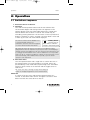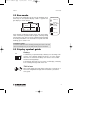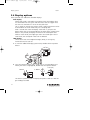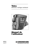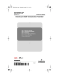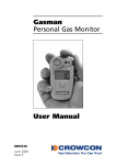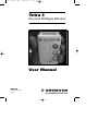
1
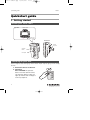
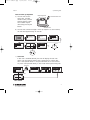
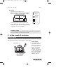
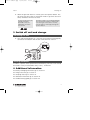
tetra 3 manual.qxp 23/01/2006 17:09 Page i Tetra 3 Personal Multigas Monitor User Manual M07654 December 2005 Issue 1 tetra 3 manual.qxp 23/01/2006 17:09 Page ii 4. Safety information: • Read and understand all instructions in the operation section of this manual before use. • Do not substitute components as this may impair intrinsic safety and invalidate warranty. • Observe all warnings and instructions marked on the unit and within this manual. • Observe site health and safety procedures for gases being monitored and evacuation procedures. • Make sure you understand the screen display and alarm warnings. • If this product is not working properly, read the troubleshooting guide or call Crowcon. • Ensure qualified service personnel change sensors and operating system. • Ensure maintenance and calibration are carried out in accordance with the procedures in the manual. 5. 6. 7. 8. Compliance with the Essential Health and Safety Requirements has been assured by compliance with IEC 60079-0, 60079-1,60079-11, EN61779-5, as certified by Baseefa. Compliance with gas detection performance standards EN50054, EN50057, EN61779-1, EN61779-4 and EN50104. Repair of this equipment and gas sensor replacement shall be carried out by the manufacturer or in accordance with the applicable code of practice. If the equipment is likely to come into contact with aggressive substances, then it is the responsibility of the user to take suitable precautions that prevent it from being adversely affected, thus ensuring that the type of protection is not compromised. The rechargeable battery must only be charged in non-hazardous (safe) areas by connection to the specified Crowcon charger power supply. The equipment is not certified for use in atmospheres containing more than 21% oxygen. Instructions specific for use in hazardous areas The following instructions apply to equipment covered by certificate numbers: Tetra 3 = Baseefa 05ATEX0187 Tetra 3 = IECEx BAS 05.0059 The following information covers all relevant points listed in clause 1.0.6 of the EHSR’s of the ATEX directive. S AS IFI ED CL 1. The certification marking is as follows: 66Y6 ONLY AS TO INTRINSIC SAFTEY FOR USE IN HAZARDOUS LOCATIONS UL CLASS I, DIV I, GROUPS A,B,C,D TEMPERATURE CODE T4 FOR INTRINSIC SAFTEY PRECAUTIONS SEE MANUAL WARNING UNDERSTAND MANUAL BEFORE OPERATING ONLY CHARGE BATTERY IN A NON HAZARDOUS AREA -4F/-20 C Ta 131F/55 C EEx ia d IIC T4 -4F/-20 C Ta 131F/55 C IEC Ex ia d IIC T4 BASEEFA05ATEX0187 IECEx BAS 05.0059 1180 II 2G OX14 1DY UNITED KINGDOM 2. The equipment may be used in zones 1 and 2 with 3. group IIA, IIB, and IIC flammable gases, temperature classes and vapours T1, T2, T3 and T4. The equipment is certified for use in ambient temperatures in the range –20°C to +55°C (-4 to +131 F). The equipment should not be used outside these ranges. Area Classifications: Zone 1: An area classified as Zone 1 is likely to have ignitable concentrations of flammable gases, vapours or liquids present under normal operating conditions. Zone 2: An area classified as Zone 2 is not likely to have ignitable concentrations of flammable gases, vapours or liquids present under normal operating conditions. Crowcon Detection Instruments Ltd 2 Blacklands Way, Abingdon OX14 1DY UK Tel. +44 (0)1235 557700 Fax. +44 (0)1235 557749 www.crowcon.com Email: [email protected] © Copyright Crowcon Detection Instruments Ltd 2005. All rights are reserved. No part of the document may be photocopied, reproduced, or translated to another language without the prior written consent of Crowcon Detection Instruments Ltd. Publication number: M07654 First edition: December 2005 tetra 3 manual.qxp 23/01/2006 17:09 Page iii Tetra 3 Personal Multigas Monitor Contents Unpacking ................................................1 Quickstart guide ........................................2 Introduction ..............................................6 Operation ..................................................8 Batteries ..................................................12 Alarm indications ....................................13 Fixing accessories ....................................14 Flow sampling ........................................15 Maintenance and calibration....................20 PC interface and software........................21 i-module replacement ..............................22 Specification ............................................24 Accessories and spare parts ....................25 Troubleshooting guide ............................27 Appendix: Limitations of sensors..............28 tetra 3 manual.qxp 23/01/2006 17:09 Page iv tetra 3 manual.qxp 23/01/2006 17:09 Page 1 Tetra 3 Unpacking Tetra 3 Personal Multigas Monitor Thank you for purchasing the new Tetra 3 Personal Multigas Monitor. Tetra 3 has redefined portable gas monitoring and will give you years of unparalleled service and reliability. Please read the instructions carefully before use. Keep the manual for future reference. Unpacking Remove the Tetra 3 Personal Multigas Monitor from the packaging. The Tetra 3 accessories will be located in the bottom of the box. Check the contents are complete, you should have: • Tetra 3 unit; • Charger and power supply; • A configuration report detailing the sensors installed, alarm settings and a calibration certificate; • Optional accessories such as aspirator plate, aspirator bulb and comms lead. Battery check The Tetra 3 Personal Multigas Monitor has a lithium-ion rechargeable battery. Tetra 3 will operate for a minimum of 16 hours when fully charged. Tetra 3 uses a Li-ion battery pack and should arrive with sufficient charge so that the unit can be used straight out the box. However, if this is the first time you have used the Tetra 3 unit, you may need to charge the batteries to attain the full 16 hour operating time. The actual operating time will depend on the types of sensors installed. Warning: rechargeable units Do not attempt to use any other charger with this unit except the one supplied by Crowcon. Failure to comply could invalidate safety certification and may result in permanent damage to the unit. 1 tetra 3 manual.qxp 23/01/2006 17:09 Page 2 Quickstart guide Tetra 3 Quickstart guide 1. Getting started Review your Tetra 3 unit Top view 4 Alarm LEDs Operator LCD display screen Side view Pocket clip lever Operator button Front plate Switching on your unit Tetra 3 requires little setting up, follow these simple steps to get your unit ready for use. 1. Ensure the unit is in clean air. 2. Switch on Press and hold the operator button until the red LED flashes. The operator display screen will light up and the unit will begin a warm up sequence. 4s 2 tetra 3 manual.qxp 23/01/2006 17:09 Page 3 Tetra 3 Quickstart guide Tetra 3 warm up sequence a) The unit will test the alarm LEDs, sounder, vibration alerts, and the operator display screen. The sounder may be silenced by pressing the button. LEDs Alarm test Sounder Alarm test Vibration test b) The unit will continue through a warm up sequence as shown below, this will take approximately 45 seconds. CROWCON Tetra3 Tetra3 vs. 1.00 CH4 NEXT CAL i %LEL CO Gas Detection You .. ppm i ppm O2 Wed 5-Sep-2005 14:02:49 1-2 m AUTO ZERO? 5-Jan-2005 H2S TODAY IS i % Click to confirm in 7 secs ! c) Auto zero If auto zero is enabled (default), the unit will display the auto zero menu. Press the operator button with a single click to confirm auto zero. If the operator button is not pressed within the 10 second time out, Tetra 3 will proceed directly to Run mode without performing zero. Auto zero AUTO ZERO AUTO ZERO? i Auto zero in 0.0 progress Click to confirm in 7 secs AUTO ZERO AUTO ZERO 0.0 CH4 H2S Co O2 0.0 CH4 H2S Co O2 No auto zero CH4 %LEL CO ppm OK 20.9 0.0 H2S ppm 0 0.0 O2 % Run mode 3 tetra 3 manual.qxp 23/01/2006 17:09 Page 4 In the event of an alarm Tetra 3 Run mode Your unit is now ready to use. Below is a typical screen display showing the unit in normal gas monitoring Run mode. CH4 %LEL CO ppm Warm up Flashing icon, Tetra3 OK running 0 0.0 normally 20.9 0.0 H2S OK Screen Icons ppm O2 % Familiarise yourself with the gases being monitored in your unit and make sure you understand site health and safety procedures in the event of alarm conditions. Battery Auto zero Confidence signals In normal Run mode, Tetra 3 will emit a short beep every 10 seconds and the OK icon flashes to show operational health. 2. In the event of an alarm Alarm signals In the event of gas concentrations exceeding the alarm thresholds for any gas being monitored, Tetra 3 will activate the alarm signals. Alarm signals The red and blue Alarm icon alarm LEDs will flash, the sounder will emit a loud, fast series of beeps, the internal 2 vibrator alarm will 0 0.0 activate. The operator 16.7 0.0 screen will display the gas in alarm and the alarm level. See the figure to the left. CH4 %LEL CO ppm H2S ppm % O2 Gas example under alarm 4 tetra 3 manual.qxp 23/01/2006 17:09 Page 5 Tetra 3 Switching off 1. When the gas level returns to normal, press the operator button. This will reset your Tetra 3 unit to normal Run mode. If gas levels are still in alarm, the button will have no effect. For any one gas, there are normally two alarm thresholds. These are indicated by the alarm icons shown. The Tetra 3 alarm is set to latch by default. The unit will still continue in alarm mode even when gas levels return to normal, until the alarm is cleared, by pressing the operator button. 1 2 3. Switch off unit and storage Switching off unit 1. Press and hold the button for 5 seconds. The shut down menu appears, continue to hold button until the unit counts down to shut off. CH4 %LEL CO OFF IN 0.0 ppm OK 0 4 sec 20.8 0.0 H2S ppm O2 % Storing conditions In order to optimise sensor performance and lifetime, your Tetra 3 unit should be stored in a safe, non-hazardous area, 0-30°C, 10-90%RH. 4. Additional information For For For For For battery recharging information go to section III. fixing accessories go to section V. sampling section go to section VI. calibration information go to section VII. troubleshooting guide go to section XII. 5 tetra 3 manual.qxp 23/01/2006 17:09 Introduction Page 6 Tetra 3 I. Introduction Thank you for purchasing the new Tetra 3 Personal Multigas Monitor. Tetra 3 is a portable multigas detector, designed to be carried or worn by individuals working in hazardous environments such as confined spaces. It is suitable for use in Zone 1 and 2 hazardous areas. Tetra 3 can monitor up to four different gases and display the readings simultaneous on a display screen. Alarm warnings are given through a combination of a loud audible alarm, a bright visual alarm of blue/red flashing LEDs and an internal vibrator. Tetra 3 is fitted with modular, plug and play gas sensors. Each sensor carries an intelligent processor which contains calibration and sensor information. Tetra 3 is operated using a Lithium-ion rechargeable battery. A charger is available with a range of options. At Crowcon we recognised the need for a reliable and robust personal monitoring system, which is both lightweight, compact, easy to use and cost effective. Tetra 3 has a single operator button, and an intelligent user-friendly display with backlight. Gas levels are continuously monitored providing normal gas readings, peak readings and time weighted averages (TWA). Tetra 3 is a diffusion sampling instrument with an option to use a hand-operated aspirator. Configuration and data/event logging is handled by Crowcon Portables PC software, the PC communication link being provided through the charger. Tetra 3’s shape and design makes it comfortable to wear and as non-intrusive as possible, with a non-slip grip for better handling. Extra accessories, such as shoulder strap and chest harness, can be purchased. Tetra 3 has been designed from top to bottom to bring you ease of use, low maintenance and extremely high reliability. Through an innovative and rigorous design process, we have combined several features from our reliable Tetra and Gasman products to produce the new Tetra 3. i-module gas sensor Tetra 3 uses unique plug and play i-module sensor technology. Each sensor unit incorporates its own intelligent processor holding sensor configuration and calibration data. Different sensor modules can be purchased, and once inserted, are immediately ready to run. Tetra 3 can operate with up to three sensors and display simultaneously, information and gas readings, for all the sensors, on one screen. This means no redundancy and assured future investment in your Tetra 3 unit, allowing you to swap sensors between units or configure your unit, 6 tetra 3 manual.qxp 23/01/2006 Tetra 3 17:09 Page 7 Introduction as appropriate, to your current needs. Plug and play will ease maintenance time and cost, and the intelligent modular system will remove the need to calibrate each sensor. Additional i-modules can be purchased, pre-calibrated from your local supplier. Reliable, anti-shock mechanics and robust housing The Tetra 3 housing is built from resilient material, giving it strength and flexibility to withstand the hardest of working conditions, water and dust tight to IP65, and with a non-slip grip. The case has been carefully designed to make servicing easy and at the same time very rugged. If the unit is dropped, there will be no disruption of power or function, ensuring reliability and service for years to come. Software The processes used to design and develop the Tetra 3 software ensure a high degree of reliability and robustness. Thus Tetra 3 has been designed to be a truly reliable personal gas monitoring system. The internal circuitry includes an external watchdog, where the software monitors for any malfunction within the unit and will display an error warning to the user should they occur. 7 tetra 3 manual.qxp 23/01/2006 17:09 Page 8 Operation Tetra 3 II. Operation 2.1 Switch-on sequence 1. Ensure the unit is in clean air. 2. Switch on Press and hold the operator button until the two red LEDs flash. The instrument begins with testing all the LCD segments on the operator display screen, the red and blue alarm LEDs, sounder and internal vibrator alert for about 5 seconds. The sounder may be silenced by pressing the button. The unit enters a warm up mode and displays a sequence of screens, see page 3 for more details. At the end of warm up, the auto zero menu will be displayed. The auto zero function can be disabled or set to run automatically, without user confirmation: auto zero menu will not appear. See section VIII PC Interface and software. Battery check Use this time to check there is sufficient charge in the battery pack ! NB. During the warm up sequence, the date for next calibration will be displayed. If the date has expired or has passed, the Tetra 3 unit will display a warning message that calibration is due. The instrument can still function, but it is strongly recommended the unit is sent for calibration as soon as possible. Tetra 3 can be set, using the Portables PC software, for the instrument to shut down automatically, if the calibration date is passed, to prevent further operation of the instrument. 3. Auto zero menu Press the operator button with a single click to confirm auto zero. If the operator button is not pressed within 10 seconds, Tetra 3 will proceed directly to Run mode without performing a zero. Flammable and toxic sensors will be set to read zero and the oxygen sensor to read 20.9%. NB. If auto zero fails, a warning message will be displayed and an ‘X’ will appear against the sensor that has failed. Switch off To switch off the unit, press and hold the operator button for 5 seconds. A shut-down menu ‘OFF IN’ will appear. Continue to hold button until the unit counts down to shut off. 8 tetra 3 manual.qxp 23/01/2006 17:09 Page 9 Tetra 3 Run mode 2.2 Run mode The Tetra 3 unit will display up to four gas readings simultaneously on the operator display screen. A typical four gas display is shown below. CH4 %LEL CO O2 Warm up Flashing icon, Tetra3 OK running normally 20.9 0.0 ppm OK 0 0.0 H2S ppm Screen Icons % Battery Auto zero Each channel will display the gas name, units and current value. Familiarise yourself with the gases currently being monitored in your unit. Ensure you understand site health and safety procedures. For information on peak and TWA readings, go to section 2.4. Confidence signals To reassure users the unit is working correctly, the Tetra 3 unit will emit a short beep every 10 seconds and the OK icon will flash. 2.3 Display symbol guide Battery Full ! A full battery is represented by a battery icon showing a full six bars. A low battery charge will show 1 to 2 bars. When zero bars are shown the battery icon flashes. The sounder will emit warning bleeps. If the battery becomes too low, Tetra 3 will display a ‘Battery low’ warning message and switch off. TWA alarm Tetra 3 will display the TWA alarm when the 15 minute or 8 hour time weighted average alarm threshold is passed for toxic gases. 9 tetra 3 manual.qxp 23/01/2006 17:09 Page 10 Display options Tetra 3 2.4 Display options Tetra 3 provides two additional selectable displays: Peak display When Peak mode is selected the instrument shows the highest value for flammable and toxic gases and the lowest value for oxygen since the unit was switched on or since the last peak clear. This is useful for vertical entry checks where a whole instrument can be lowered down the shaft rather than just a sampling tube. After 5 seconds the screen will display 'Peak Clear'. If you press the button within the 10 second countdown, the peak value is cleared. If the button is not pressed, the display will revert to the stored peak value. Whilst in Peak mode, new higher gas values are stored. Upon exit of Peak mode, the stored peak values are not deleted. TWA display Shows the 8 hour time weighted average (TWA), for toxic gases, monitored since last turn on. 1. To view the additional display option menu, double-click the operator button. CH4 %LEL CO ppm OK Gas0 Peak 20.8 0.0 TWA H2S ppm O2 % Zero 0.0 2. Press the operator button with a single click to scroll through the list. When your choice is highlighted, double-click the operator button. Peak display 1. Scroll 2. Select ppm OK 0 Gas Peak 0 TWA Zero 20.8 % The Tetra 3 operator screen will display the peak or TWA icon and the gas readings recorded. 10 tetra 3 manual.qxp 23/01/2006 Tetra 3 17:09 Page 11 Event logging Zero The Tetra 3 instrument can perform an auto zero by selecting the Zero function from the menu. When Zero is completed, the instrument will return to normal operation. 2.5 Logging Tetra 3 incorporates data and event logging which can be accessed using the communications link with Portable PC software. See section VIII. The Tetra 3 event log records the time and date for a number of operating and diagnostic events including: • Switch on and switch off • Level 1, Level 2 and Time Weighted Average Alarms, alarm on, alarm off and the peak level during the alarm • Zero, calibration and gas test with success or failure • Pellistor saver on and off • The battery condition is logged every time the Tetra 3 is switched on or off, and when it is placed into or removed from the charger • Datalogging records reading sets data at a predetermined time interval, usually set to one minute. 11 tetra 3 manual.qxp 23/01/2006 17:10 Page 12 Batteries Tetra 3 III. Batteries 3.1 Rechargeable batteries Tetra 3 uses a rechargeable Lithium-ion battery which must only be charged using a Crowcon battery charger. A 5 hour recharge from flat will provide at least 12 hours operating time. A fully charged battery will provide more than 16 hours of continuous use. Charging the batteries 1. Ensure you are in a safe area. 2. Plug the charger power supply into a mains socket. 3. Connect the power supply to the charger. Insert the Tetra 3 into the charger. Switch on the charger's power supply. The unit would normally be left switched off for charging. When charging is complete the charger LEDs change from red to green. If the unit is switched on during charge the normal display battery icon sweeps from empty to full. On disconnecting the charger power supply this display Communications icon will update in 20 seconds to socket show actual charge state. In Run mode, the battery icon will display six bars when it is full. 4. Remove the Tetra 3 from the charger and switch on to use. Battery fully charged Tetra warning message Battery full WARNING i Low battery 25 Battery needs recharging The charging time will be longer if the unit is switched on during charging. 12 tetra 3 manual.qxp 23/01/2006 17:10 Page 13 Tetra 3 Alarm indications IV. Alarm indications Tetra 3 provides two instantaneous alarm levels for each installed sensor, designated level 1 and level 2. For toxic gas sensors, there are also two time weighted average alarms (TWA), one for short term exposure (STEL): based on a 15 minute time weighted average, and the second TWA alarm is for long term exposure: based on a 8 hour time weighted average. Alarm configurations are set via the Crowcon Portables PC software. The following settings can be made: Alarm thresholds for each sensor: Level 1 1 2 and level 2 alarms can be set for each individual gas sensor. Alarm type: This can be set to rising levels of gas concentration, or as falling. Oxygen are set to falling for deficiency monitoring as a default. Alarm latching: Alarms can be set to be latched or unlatched. Latched alarms will require the operator button to be pushed in order to clear the alarm. This is the default setting. Unlatched alarms will clear automatically when the gas hazard has passed. Alarm mute: The sounder can be set to mute for level 1 alarm only; pressing the operator button during an alarm condition i.e. presence of hazardous gas, will silence the sounder and stop the vibration alarm. The alarm LEDs will continue to flash. Alarm sounder tone: Different tones can be selected to achieve the best performance for the monitoring conditions available. In the event of a Time Weighted Alarm (TWA) In the event the 15 minute or the 8 hour TWA is triggered, Tetra 3 will go into alarm and display the TWA icon with the toxic gas readings. Neither the 15 minute alarm or 8 hour alarm can be cleared. 13 tetra 3 manual.qxp 23/01/2006 17:10 Page 14 Fixing Accessories Tetra 3 V. Fixing Accessories Belt clip Tetra 3 has a strong alligator clip located on the back of the unit. Lifting the small lever will allow the unit to be attached to a belt more easily. Universal harness plate Crowcon provide a universal harness plate which can be used with either a chest harness or a shoulder strap. How to wear your Tetra 3 unit Chest harness Use the M3 fixing on the back of your Tetra 3 unit to attach the chest harness plate. Create a chest harness by attaching one strap to the top connectors, to go around the neck, and the other to link around the waist using the side connectors. Adjust the lengths until the Tetra 3 unit is in a comfortable working position. Shoulder/neck connectors Universal harness plate Shoulder strap With the universal harness plate in place, attach the shoulder strap accessory onto the top connectors. Adjust to a comfortable working position. See accessories, section XI, for full list. 14 tetra 3 manual.qxp 23/01/2006 17:10 Page 15 Tetra 3 Flow sampling VI. Flow sampling Attaching the flow adaptor plate To perform manual sampling using Tetra 3, a flow adaptor plate must be fitted onto the front of the instrument. Flow adaptor Gas in Gas out 1. To fit the flow adaptor plate, clip the plate in place over the sensor grills and screw the thumbscrew until the plate is tightly fitted into place. 2. Attach the sampling tube or flow accessory onto the gas inlet nozzle. 3. Attach the aspirator bulb onto the gas outlet nozzle. 4. To remove the flow adaptor plate, unscrew the thumbscrew and lift the plate away from the instrument. The sampling tube supplied is normally a 2m (6ft) length. Longer lengths of sampling tube can be provided, but will increase the time taken to get a sample from the point of sampling to the Tetra 3 instrument. When using an extended length of tubing a response time test is recommended. Gas of known concentration should be sampled along the full length of tubing to be used and the time taken for the sensor reading to reach the known gas levels should be noted. This time should be used as the minimum for sampling before readings should be taken. 15 tetra 3 manual.qxp 23/01/2006 17:10 Flow sampling Page 16 Tetra 3 Diffusion instruments When using the manual aspirator kit, adopt a consistent style whilst using the hand aspirator. Crowcon recommend squeezing once per second to achieve a flow rate of approximately 0.5 - 1 litre/min. At least 10 pumps per sample are recommended. 16 tetra 3 manual.qxp 23/01/2006 17:10 Page 17 Tetra 3 Gas testing Tetra 3 gas test accessory kit The Gas Test Accessory is a gas testing kit designed to enable gas testing of the Tetra 3 multigas detector using a specially formulated, high stability long life quad gas mix. It can be used with Tetra 3 units having sensors for Flammable, Oxygen, Carbon Monoxide and Hydrogen Sulphide gases, and all Tetra 3 units with these sensors can be gas tested using the kit. 6.1 Gas testing Gas testing checks the sensor is responding within set limits to an applied gas of known composition. This can be performed as often as desired, but would usually be carried out each time the Tetra 3 is issued for use. The Tetra 3 itself will determine Pass/Fail status for the gas test. In order to perform successful gas tests ensure: • The quad gas mixture used has the correct gas concentration, and that it is within the validity date specified by the supplier. • The gas flow path is leak tight. It is important to check that the flow plate is properly fitted to the Tetra 3, and the outlet tubing is not restricted in any way, nor additional tubing length used. The Gas Test Accessory Kit is supplied in a convenient carry case and comprises; a gas cylinder containing the quad gas mix, a 'Trigger' regulator with interconnect tubing, a magnet - used to activate Test mode, an aspirator plate to attach to the Tetra 3 and a vent line. The Trigger regulator can be operated in two ways: (1) squeeze and hold - allows gas flow as long as the lever is held in, or (2) by lifting the lever - the flow is locked on. 6.2 How to perform a gas test 1. Ensure your Tetra 3 unit is switched on and in normal operation. 2. Clip the flow plate onto the front of the unit and attach the hose from the Trigger regulator. Attach the outlet hose to ‘vent gas away’ - do not extend this hose and do not restrict or allow kinks. 3. Swipe the magnet over the bubble label on the front of the unit, near the main button. Your Tetra 3 will begin the Gas Test and show 'GAS TEST' on the display. A countdown progress bar will also appear at the bottom of the display. 17 tetra 3 manual.qxp 23/01/2006 17:10 Page 18 Field calibration Tetra 3 4. Operate the Trigger regulator and apply gas to the Tetra 3 whilst the progress bar is counting down. 5. Wait for the progress bar to complete (typically 30-45 seconds). A pass or fail message will appear. To continue using the instrument, disconnect the test gas and press the main button. This will return the unit to its normal operating mode. (The unit is comparing what it measures from the bottle with the standard gas values it knows should be in the bottle.) 6.3 How to perform a field calibration test To perform a field calibration test, you must first Zero your Tetra 3 unit 15 minutes or less before commencing the gas test instructions. 1. Follow steps 1 to 3 given in 6.2, Tetra 3 will display an alternate screen message; Calibrate? Click to Confirm In 10 seconds Press the button within 10 seconds to confirm Calibration. If the button confirmation for calibration is not made within 10 seconds then the process will revert to gas test as in 6.2. 3. Apply calibration gas following step 4 in 6.2. Tetra 3 will display a progress bar at the bottom, the names of the gas sensors fitted are shown in reverse image with a cross beside each. Operate the Trigger regulator and apply gas to the Tetra 3 whilst the progress bar is counting down. As gas flows the Tetra 3 allows the sensors to respond and then adjust the value for each gas channel to match the stored calibration gas value within each sensor i-module. Provided all channels calibrate successfully within the allowed time the calibration will be designated successful. If any channel does not calibrate successfully it will remain marked with a cross and screen a message ‘Gas test failed’ and ‘Send for calibration’ will be displayed. A tick will appear against each channel as the unit passes the test 4. To abort the Calibration test press the button at any time whilst the test is in progress. 18 tetra 3 manual.qxp 23/01/2006 17:10 Page 19 Tetra 3 Gas test/calibration troubleshooting 6.4 Cal/Test This can arise if having selected and confirmed calibration, one or more (but not all) of the sensors are not calibrate-enabled. In this case calibrate-enabled channels will calibrate, and non-enabled channels will Gas Test (bump) only. Oxygen sensors are by default not calibrate-enabled, as they are calibrated to 20.9% in fresh air in Zeroing. 6.5 Gas test/calibration troubleshooting Symptom Possible Cause Action No response to gas Gas cylinder empty Check gauge, replace cylinder as needed Hose blocked or kinked Ensure no restriction to flow Gas cylinder empty Check gauge, replace cylinder as needed Gas cylinder out of date Check date and replace as needed Hose blocked or kinked Ensure no restriction to flow Calibration drifted Calibrate Tetra 3 Gas flow not started immediately Repeat test, starting gas immediately Gas cylinder empty Check gauge replace bottle as needed Gas cylinder out of date Check date and replace as needed Hose blocked or kinked Ensure no restriction to flow Calibration drifted Calibrate Tetra 3 Stabilisation time too short Reset using PC software Menu Zero not performed Field calibration not enabled in Tetra 3 unit. Select Zero from menu Send for re-configuration Tetra 3 fails gas test Tetra 3 fails calibration Tetra 3 passes gas test but will not enter calibration mode Note: Remove regulator from gas cylinder when not in use over a prolonged period. For parts list, see section XI. 19 tetra 3 manual.qxp 23/01/2006 17:10 Maintenance and Calibration Page 20 Tetra 3 VII. Maintenance and Calibration Tetra 3 is designed to operate almost maintenance free under most conditions. However, some small items of routine maintenance are recommended. General To keep the display panel and operator button free from dirt build up, regularly wipe over your Tetra 3 unit with a damp cloth. Zero and calibration Tetra 3 is supplied with an auto zero function on start-up. This function can be configured to operate automatically, on user confirmation (see quick start guide), or can be disabled. This configuration can be set with the Crowcon Portables PC software, see section VIII. Tetra 3 also has a zero function in the menu. See section II, item 2.4. Crowcon recommends, as a minimum, a monthly gas test to confirm sensor operation. A test gas of known composition, needs to be applied, to verify sensor response and alarm function. Instrument calibration of all sensors should be performed at regular 6 monthly intervals. Calibration method Tetra 3 calibration can either be performed using the Portables PC software or by use of the Gas Test Accessory Kit. Using the Portables PC software allows calibration using either single gas mixtures, and calibrating each sensor in turn, or using a multigas mixture for simultaneous calibration. The Gas Test Accessory Kit allows calibration on a quad gas mixture for the standard 4 gas combinations of flammable, oxygen, carbon monoxide and hydrogen sulphide. 20 tetra 3 manual.qxp Tetra 3 23/01/2006 17:10 Page 21 PC interface and software VIII. PC interface and software Tetra 3 can be connected to a PC using the single way charger unit with optional PC interface. The charger unit is fitted with a D-type 9 pin male RS232 socket which is located at the rear of the charger, see diagram below. The PC requires Crowcon Portables PC software. A USB-RS232 adapter is also available from Crowcon. The software provides the user with access to reconfigure alarm levels, operation, run calibrations, print reports and to access data and event log files. Set-up 1. Install Portables PC software on PC and attach the RS232 cable to the charger and PC. 2. Switch on the Tetra 3 unit and drop it into the charger unit ensuring it is upright and the display is facing forward. 3. Open the Portables PC software and either use the Wizard or the Engineer’s Form, select Tetra 3 and upload the configuration. For more information on using the Crowcon Portables PC software, see installed help file. 21 tetra 3 manual.qxp 23/01/2006 17:10 Page 22 i-module replacement Tetra 3 IX. i-module replacement 1. Ensure you are in a non-hazardous (safe) area. Switch off the unit 2. Remove any accessories, such as the flow adaptor, if fitted. 3. Remove the cover by unscrewing the four M3 screws as shown in the drawing, point With care, withdraw the battery with plastic holder downwards. 1 Removing an installed i-module 1. Locate the i-module connection ribbon, squeeze the two retaining lugs, on the i-module board, toward each other and pull out slightly, this will release the ribbon. 2. Gently pull the i-module out of the unit. There may be some resistance at first, as the seal between the sensor and the front case is broken. 22 tetra 3 manual.qxp 23/01/2006 17:10 Page 23 Tetra 3 i-module replacement Installing or replacing an i-module If replacing an i-module with one of the same type, instrument specific configuration will be retained. If replacing with a different i-module its default configuration will be loaded. 1. Unwrap the i-module from any packaging. If you are installing a new i-module into a currently unused slot, you will first need to remove the dummy i-module. Follow the i-module removal instructions to do so. 2. Ensure the gasket is in place in the sensor. Place the new sensor in the vacant space and push down gently. 3. Attach the ribbon connector by squeezing the two retaining lugs , on the module board, toward each other and pulling out slightly. Slide the ribbon into the slot. Push the retaining lugs back toward the sensor, this will grip the ribbon firmly. 4. If using a dual sensor, always place this in the slot furthest from the display. Warning Do not twist the connection ribbons. Do not pull the i-modules too far from the PCB board, to prevent damage to the cabling or electrical connections Re-assembling the Tetra 3 unit 1. Ensure that all i-modules are seated in their correct positions and all ribbon cables are folded neatly between the i-modules and the main unit. Put the battery and plastic holder back into their original positions. 2. Switch on your Tetra 3 unit. The new sensor will be automatically identified. Check the filters and gaskets are all in good condition. Replace if any items are faulty. Refer to the troubleshooting guide if necessary. 23 tetra 3 manual.qxp 23/01/2006 17:10 Page 24 Specification Tetra 3 X. Specification 24 Dimensions 71 x 114 x 48 mm (2.8 x 4.5 x 1.9 inches) Weight 295 g unit, including pocket clip and 3 sensors. Housing, degree of protection Ingress protection IP65 IP67 Operating temperature -20 to +55°C (-4 to +131 F) Humidity 0-99% RH, non-condensing for continuous operation Display 128 x 64 pixel Warm up time 45 seconds approximately Response time (typical) (T90) : appx 20 seconds for most toxic sensors, 10 seconds for oxygen. Repeatability ±2% FSD, 6 months Explosion protection Intrinsically Safe ATEX Essential Health and Safety Requirement, clause 15.9 Safety certificate no. Baseefa05ATEX0187 IECEx BAS05.0037 Approval codes Europe: USA: Canada: ATEX II 2G EEx ia d IIC T4, (Tamb –20 to +55°C) Approvals pending. Approvals pending. Standards Safety: USA: Canada: Operation EN50014, EN50020, EN50018, 94/9/EC UL913 (Pending) CSA22.2, 152 (Pending) EN50270, EN50271 tetra 3 manual.qxp 23/01/2006 17:10 Page 25 Tetra 3 Accessories and spare parts XI. Accessories and spare parts Accessory list Crowcon part number Description S011952 C01877 C03327 Aspirator assembly Tetra 3 gas test accessory kit Quad gas mixture for gas test accessory kit, 34 litre bottle 50%LEL methane, 250ppm carbon monoxide, 15ppm hydrogen sulphide, 18% oxygen balance nitrogen. For calibration gas contact Crowcon, as the required gases depend upon your sensor combination. Single way chargers C011018 12 V DC input single way charger C011020 Single way charger with 230 V UK style power supply C011021 Single way charger with 230 V EUR style power supply C011022 Single way charger with 110 V US style power supply C011023 Single way charger with 90-260 V inline power supply C011035 Single way charger with 230 V inline power supply C011036 Single way charger with 110 V inline power supply C01296 Vehicle lighter socket lead C011019 Single way combined charger and PC interface C011024 Single way charger/interface with 230 V UK style power supply C011025 Single way charger/interface with 230 V EUR style power supply C011026 Single way charger/ interface with 110 V US style power supply C011027 Single way charger/interface with 90-260 V inline power supply C011037 Single way charger/interface with 230 V inline power supply C011038 Single way charger/interface with 110 V inline power supply i-modules: S011424 S011436 S011437 S011439 S011440 S011423 S011421 S011422 S011953M 0-100% LEL methane 0-100% LEL propane 0-100% LEL pentane 0-100% LEL butane 0-100% LEL ethylene 0-25% oxygen O2 0-50ppm hydrogen sulphide H2S 0-500ppm carbon monoxide CO 0-50ppm H2S/0-500ppm CO dual i-module. *There are alternative flammable sensors for different applications. Contact Crowcon with the instrument serial number to check correct sensor type. 25 tetra 3 manual.qxp 23/01/2006 17:10 Page 26 Accessories and spare parts Sampling accessories: S011952 Aspirator plate M04897 Aspirator plate and gasket C01757 Telescopic aspirator probe C01097 3 foot sample probe M04032 Aspirator hose (please specify length in feet) C03328 6 m drop line C01245 Water trap Carrying and wearing: C01952 Universal harness plate C01843 Shoulder strap C01844 Chest harness strap kit Communications: E07532 PC interface head C02097 USB to RS232 adaptor C01832 Portables PC software CD Spares / consumables: S011960 Rechargeable Li-ion battery pack assembly C01851 Aspirator bulb C01853 Dummy sensor module M04482 i-module O-ring seal 26 Tetra 3 tetra 3 manual.qxp 23/01/2006 17:10 Page 27 Tetra 3 Troubleshooting guide XII. Troubleshooting guide Symptom/ error message Cause Action Instrument won't switch on No confidence beep Gas reading when no gas present Unstable/inaccurate gas reading Flat battery. Function disabled. Zero drifted. Auto zero failed Zeroing in contaminated atmosphere Zeroing in contaminated atmosphere The calibration due date has passed Contrast setting wrong Recharge or replace battery. Reconfigure with PC software. Restart instrument in clean air. Do not use; exit hazardous area immediately. Return instrument for recalibration or sensor replacement. Switch off and restart in clean air. Cannot Auto zero due to alarm Calibration expired LCD too faint/dark Sensor failure Switch off and restart in clean air Send for calibration Adjust using Portables PC software. Fatal/Auto shut Service User alert Calibration Configuration 27 tetra 3 manual.qxp 23/01/2006 17:10 Appendix: Limitations of sensors Page 28 Tetra 3 Appendix: Limitations of sensors Sensor limitations The sensors used in Tetra 3 have limitations common to all such gas sensors, and users should be aware of the points listed below. Crowcon can advise on particular situations and suggest alternative sensors if the instrument is likely to experience extreme conditions. Tetra 3 uses a catalytic flammable gas sensor, which measures the flammability of the gas. for this reason, readings displayed on the unit will be unreliable over concentrations of approximately 120% LEL. Oxygen is necessary for catalytic sensors to operate. A 'pellistor saver' is used to disconnect power to the pellistor sensor in the event of over-range to prevent burn out. This locks out for 200 seconds after which a button press will reconnect power to the pellistor. If the sensor power is reconnected when the unit is exposed to an over-range gas concentration there is a risk of damage to the pellistor sensor. Restart should be carried out in a known fresh air environment. Depleted oxygen levels can reduce the flammable gas reading, and if oxygen levels are below safe breathing limits it should be assumed that the flammable reading is low. Electrochemical gas sensors contain chemicals. Extreme levels of humidity can also cause problems. The sensors are rated for an (average) ambient of 15-90% R.H. However they are used from the tropics to deserts to tundra without this normally being a problem. Water should not be allowed to collect on the sensors as this may impede gas diffusion. Persistent exposure to high levels of toxic gas will shorten the life of toxic sensors. If the high level gas is corrosive (e.g. hydrogen sulphide) damage may occur over time to metal components. Sensors may be cross sensitive to other gases. If unsure, contact Crowcon or your local agent. 28 tetra 3 manual.qxp 23/01/2006 17:10 Page 29 tetra 3 manual.qxp 23/01/2006 17:10 Page 30 tetra 3 manual.qxp 23/01/2006 17:10 Page 31 tetra 3 manual.qxp 23/01/2006 17:10 Page 32 UK Office Crowcon Detection Instruments Ltd 2 Blacklands Way, Abingdon Business Park Abingdon Oxfordshire OX14 1DY United Kingdom Tel: +44 (0)1235 557700 Fax: +44 (0)1235 557749 Email: [email protected] Web site: www.crowcon.com USA Office Crowcon Detection Instruments Ltd 21 Kenton Lands Road, Erlanger, Kentucky 41018-1845 USA Tel: +1 800 527 6926 or 1-800-5-CROWCON +1 859 957 1039 Fax: +1 859 957 1044 Email: [email protected] Web site: www.crowcon.com Rotterdam Office Crowcon Detection Instruments Ltd Vlambloem 129 3068JG, Rotterdam Netherlands Tel: +31 10 421 1232 Fax: +31 10 421 0542 Email: [email protected] Web site: www.crowcon.com Singapore Office Crowcon Detection Instruments Ltd Block 192 Pandan Loop #05-01 Pantech Industrial Complex Singapore 128381 Tel: +65 6745 2936 Fax: +65 6745 0467 Email: [email protected] Web site: www.crowcon.com