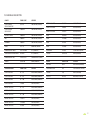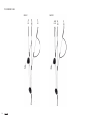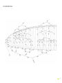
1
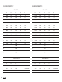
USER’S
MANUAL
ARTIK P
ARTIK P
The adventurer
NIVIUK Gliders ARTIK P
WELCOME
This manual offers all the necessary information that will familiarize you
with the main characteristics of your new paraglider. Although this manual
informs you about your glider, it does not offer the instruction requirements
necessary for you to be able to pilot this type of wing. Flying instruction
can only be taught at a paragliding school recognized by the Flying
Federation of your country.
We wish to welcome you to our team and thank you for the confidence
that you have placed in a NIVIUK Glider.
We would like to share with you the commitment, the passion and
emotions of the Niviuk design team, which have resulted in the creation
of the new ARTIK P. Niviuk are very proud of this new glider, carefully
designed to bring you maximum pleasure whilst allowing you learn and
progress.
The legendary Artik design is now available in a lightweight version derived
from and based on the best assets found in the previous models. For the
XC, mountain or hike&fly pilots who want to explore new routes and need
lightweight compact gear.
We are confident that you will enjoy flying this wing and that you will soon
understand the meaning of our slogan: “The importance of small details”
This is the user’s manual that we recommend you to read in detail.
The NIVIUK Team.
Niviuk Gliders & Air Games sl C/ Del Ter 6, nave D 17165 La Cellera de Ter - Girona - Spain
Tel. +34 972 42 28 78 Fax +34 972 42 00 86
[email protected] www.niviuk.com
2
USER’S MANUAL
Nevertheless we remind you that it is important that you carefully read all
the contents of the manual for your new ARTIK P.
Severe injuries to the pilot can be the consequence of the misuse of this
equipment.
SUMMARY
welcome2
4.3 USING THE ACCELERATOR 11
user’s manual
2
4.4 FLYING WITHOUT BRAKE LINES
11
1. CHARACTERISTICS 4
4.5 KNOTS IN FLIGHT 11
1.1 WHO IS IT DESIGNED FOR? 4
5. LOSING ALTITUDE 11
1.2 CERTIFICATION
4
5.1 EARS 11
1.3 IN-FLIGHT BEHAVIOUR 4
5.2 4B2 TECHNIQUE 12
1.4 ASSEMBLY, MATERIALS 4
5.3 B-LINE STALL
12
1.5 ELEMENTS, COMPONENTS 6
5.4 SPIRAL DIVE
13
2. UNPACKING AND ASSEMBLY 6
5.5 SLOW DESCENT TECHNIQUE
13
2.1 CHOOSE THE RIGHT LOCATION 6
6. SPECIAL METHODS 13
2.2 PROCEDURE 6
6.1 TOWING 13
2.3 ASSEMBLY OF THE HARNESS
6
6.2 ACROBATIC FLIGHT 13
2.4 TYPE OF HARNESS
6
7. CARE AND MAINTENANCE 14
2.5 ASSEMBLY OF THE ACCELERATOR
7
7.1 maintenance
14
7.2 STORAGE
14
2.6 INSPECTION AND WING
INFLATION ON THE GROUND
7
7.3 CHECKS AND CONTROLS 14
2.7 ADJUSTING THE BRAKES
7
7.4 REPAIRS 14
3. THE FIRST FLIGHT
8
8. SAFETY AND RESPONSABILITY 14
3.1 CHOOSE THE RIGHT LOCATION
8
9. GUARANTEE 15
3.2 preparation
8
10. TECHNICAL DATA 16
3.3 FLIGHT PLAN
8
10.1 TECHNICAL DATA
16
3.4 PRE-FLIGHT CHECK LIST 8
10.2 MATERIALS DESCRIPTION 17
10.3 RISERS plan
18
3.5 WING INFLATION, CONTROL,
AND TAKE-OFF 8
10.4 suspension PLAN
19
3.6 LANDING 8
10.5 DIMENSIONS ARTIK P 21
20
3.7 FOLDING INSTRUCTIONS
8
10.6 DIMENSIONS ARTIK P 23
20
4. IN FLIGHT 9
10.7 DIMENSIONS ARTIK P 25
21
4.1 Flying in TURBULENCE 9
10.8 DIMENSIONS ARTIK P 27
21
4.2 POSSIBLE CONFIGURATIONS 9
10.9 CERTIFICATION SPECIMEN TEST 22
3
1. CHARACTERISTICS
all flying conditions, and behaving impeccably well in turbulence.
1.1 WHO IS IT DESIGNED FOR?
1.4 ASSEMBLY, MATERIALS
The ARTIK P was designed for cross country, mountain or hike&fly pilots
who want to explore new routes and need lightweight compact gear.
The ARTIK P benefits from the latest technological advances used
on other Niviuk gliders to enhance pilot comfort and improve the
performance of the RAM, DRS, LI-NK light System and 3 line profile.
1.2 CERTIFICATION
The ARTIK P has successfully passed the European EN/LTF certification.
This test was carried out in the Swiss Air-Turquoise laboratories in
Switzerland. All the commercially available sizes passed every required
test with excellent results and the ARTIK P received the EN C / LTF C
certifications for all sizes.
The ARTIK P passed the essential load test of 8G’s without experiencing
any problems.
We recommend paying special attention to the flight test report made by
the certification laboratory. The fligt test report indicates all necessary
information to know and how the new paraglider will react during each
tested manoeuvre.
It is important to take understand that each size can have a different
reaction with the same manoeuvre, and each wing size can behave
differently depending on its all up weight.
Check the certification results and figures on the last pages of this
manual or www.niviuk.com
1.3 IN-FLIGHT BEHAVIOR
With progressive, predictable and efficient handling the ARTIK P
effectively reads the air mass rather easily, seeking out and coring
thermals with efficiency and ease. It is an agile, light, predictable glider in
4
RAM.- The RAM AIR INTAKE technology presents an internal positioning
for the air intakes, providing optimal and constent internal pressure
as well as improving laminar air flow on the intrados. As a result, a
significant turbulent air buffering takes place at the leading edge for
better consistency across the speed range, and hence increasing
performance with maximum safety.
DRS.-The trailing edge was reinforced with small ribs, flattening it and
spreading the pressure out evenly for better air-flow and less parasitic
drag on this important part of the glider. The addition of these ribs gives
exceptional handling (increased efficient when turning), more control and
precision.
3LT.- Its powerful profile, a detailed internal architecture structure, and
the use of high-tech strength materials make it possible to obtain a
significant reduction of the combined suspension lines length, hence
reducing the parasite drag amount and the weight of the glider to gain
efficiency.
LI-NK light System. – The LI-NK is an ultralight system made to
connect the lines to the risers, and specially designed for mountain and
lightweight gliders. It has a higher load bearing braking point than the
traditional delta maillons without the weight. (Breaking strength LI-NK
light System: 1300 kg / Maillón: 800 kg).
The LI-NK light System is 25 times lighter and it is fitted with a locking
system providing greater efficiency at maximum load. Dyneema braid
stitched together with a locking strap.
Notice: this system has not been proven or officially certified to connect
the risers to the harness and/or the rescue parachute to the harness.
5.Push the looped end through the loop of the reinforced end (black tab)
once more.
6.Push the reinforced end loop (black tab) through the looped end to
secure them together.
7.Pull tight to secure the knot and connection.
8.Complete the operation by sliding the protective elastic sleeve over the
entire assembly.
The line plan on the ARTIK 4 combines Dyneema Liros and Vectram
Cousinun. Both of them are unsheathed lines, which are slightly more
exposed to the normal rigours and wear of our sport.
It is strongly recommended for the lines to be thoroughly inspected
by the pilot before each flight and ultimately checked by a specialized
certified repair facility or Niviuk dealer after reaching one hundred (100)
hours of flight. Keep in mind that we are dealing with high performance
materials in need of systematic maintenance at regular intervals to keep
them in top working conditions.
The fabrics used have been carefully selected for their lightweight, UV
standards and resilient properties.
1.Push the lines through the elastic sleeve, then the LI-NK light System
through the lines and the riser. The reinforced end with the black tab
should be located on the riser side first.
2.Push the upper looped end through the loop with the reinforced end
where the black tab is located.
3.Continue with the procedure in a counterclockwise motion by pushing
the looped end through the riser.
4.Push the looped end through the lines again following the same pattern.
The entire process from Olivier’s computer thorough design work to
manufacturing and final assembly must be flawless and done on a zero
tolerance basis. Precision in all phases of work is central to delivering a
perfect product to the pilot. An automated computerized lazer cutting
plotter enables the various fabric panels to be cut with ultimate precision.
The software not only guides the lazer cutter but prints the registration
marks needed for assembly. It also numbers each individual piece of
material. Machines take care of the initial phase before human handling
of the pieces begins, so to eliminate possible problematic errors that
could occur during this delicate procedure.
The lines are semi-automatically manufactured and all the sewing is
completed under the supervision of our specialists. The assembly
5
jigsaw puzzle is made easier as a result. We minimize the procedures
while making quality control more efficient. All the various parts of the
canopy are cut and assembled under the strict conditions induced by the
automation of the whole process.
All NIVIUK Gliders go through an extremely thorough and efficient final
inspection. Every single glider line is measured once the final assembly
has been completed Each wing is then individually inflated for the last
visual inspection.
Each glider is packaged following the maintenance and conservation
instructions recommended for the advanced materials. NIVIUK Gliders
are made of high quality materials for durability and best performance
delivery to meet today’s market certification requirements.
Material manufacturing information can be found on the last pages of this
manual.
you to carry out all the recommended steps required to check and inflate
the ARTIK P.
We recommend having professional supervision to conduct the entire
procedure, and have it done as it should be.
2.2 PROCEDURE
Take the paraglider out of the rucksack, open it and spread it open with the
lines on top of the intrados. Position the wing as if you were to inflate it.
Check the condition of the fabric and the lines, making sure there are no
abnormalities. Check for the maillons attaching the lines to the risers to
be fully closed and locked. Identify and if necessary disentangle the lines
from the A, B and C risers, the brake lines and the corresponding risers.
The lines must be free of entanglements and/or knots.
2.3 ASSEMBLY OF THE HARNESS
1.5 ELEMENTS, COMPONENTS
The ARTIK P is delivered to its owner together with a series of
components that, although not fundamental, do take an important part in
the use, transport and storage of the paraglider:
Correctly connect the risers to the harness karabiners. The risers and
lines can not have any twists and must be in the right order. Check for
the harness buckles to be securely locked.
2.4 TYPE OF HARNESS
• A rucksack.
•A
small fabric repair kit with self-adhesive ripstop nylon (matching the
wing’s color scheme) and replacement maillon blockers.
2. UNPACKING AND ASSEMBLY
2.1 CHOOSE THE RIGHT LOCATION
We recommend unpacking and packing your wing on a school slope or a
flat clear area, obstacle free and in low wind speed. Doing so will enable
6
The ARTIK P can be flown with most of the harnesses found on the
market today, including cocoon type models. We strongly recommend
adjusting the chest strap distance according the values used during the
certification procedure. That distance will vary depending on the chosen
harness model.
Incorrect adjustment can seriously affect the glider’s flying behavior. Too
wide a distance between the carabiners, may provide more feedback
but could affect the overall stability of the glider. Too narrow a distance
between the carabiners, would provide less feedback but also increase
the risk of developing a twist in during a large collapse. Any chest strap
adjustment other than the default certification setting would affect and alter
the glider’s behavior.
2.5 AssemBlY oF THe ACCelerATor
The acceleration mechanism of the ArTik p is activated by pushing
with your feet on the accelerator bar supplied with the wing. The
speed-bar must be properly installed and connected to the glider
before your first flight.
After installation, take into account that you will have to adjust the length
of the accelerator lines for correct use. That distance will vary according
to the length of the pilot’s legs!
it is recommended to first check the speed system compatibility with the
rest of the equipment. most paragliding schools will carry this type of gear.
2.6 iNspeCTioN ANd WiNG iNFlATioN oN THe GrouNd
once your gear has been checked and made sure that the weather
conditions are favorable, inflate your ArTik p as many times as
necessary to become familiar with its behavior.
The ArTik p inflates easily and smoothly. An over energetic inflation
is not necessary to bring the wing overhead as it will climb gently with
minimum pressure on the harness when moving forward.
The inflation sequence can be made easier by using the A risers. do not
pull on them; just accompany the natural rising arcing movement of the
wing. once the wing has climbed overhead, simply apply the correct
amount of brake pressure to keep the ArTik p above you.
2.7 AdJusTiNG THe BrAkes
The length of the main brake lines is adjusted at the factory to the length
established during certification. However, the length can be changed to
adapt to the pilot’s own flying style. in any case, we recommend flying
for a while using the default line factory settings before making any
adjustment to them. it will enable you to become more familiar with the
ArTik p and its unique flying characteristics.
The speed-bar and riser connections to the speed-bar lines are made
by nonslipping bowline knots. This configuration guaranties the same
level of safety found when using metal crimped hooks while reducing the
overall weight of the accelerator setup.
if you then decide to change the length of the brake lines, untie the knot,
slide the line through the brake link to the desired length, and strongly
re-tie the knot. Qualified personnel should carry out this adjustment.
You must ensure that this adjustment does not slow the glider down
without pilot input. Both brake lines should be symmetrical and measure
7
the same length. The most recommended knots are the clove hitch or
bowline knot.
When changing the brakes length, it is necessary to check that they
do not act when the accelerator is used. When accelerated, the glider
rotates over the C risers, the trailing edge rises. The brake lines should
be checked for proper adjustment, while taking this extra length into
consideration.
3. THE FIRST FLIGHT
3.1 CHOOSE THE RIGHT LOCATION
We recommend taking your first flight with your ARTIK P on a smooth
slope (a school training hill) or at your usual flying area.
3.2 PREPARATION
Repeat the procedures detailed in chapter 2 UNPACKING AND
ASSEMBLY in order to prepare your equipment.
3.3 FLIGHT PLAN
Make a flight plan before taking off to avoid possible flight problems later.
3.4 PRE-FLIGHT CHECK LIST
Once ready, and before taking off, make a last visual equipment inspection
to ensure that all is in order and good to go. Make sure the weather
conditions are suited for your flying skills.
3.5 WING INFLATION, CONTROL, AND TAKE-OFF
Smoothly and progressively inflate the wing (chapter 2.6 INSPECTION
8
AND WING INFLATION ON THE GROUND). The ARTIK P inflates easily
and does not require excessive energy. No tendencies to overshoot,
rendering the inflation sequence quite easy to achieve. Those
characteristics enable the pilot to be in full control and give him/her
enough time to decide whether or not to transit into the running phase
toward a successful takeoff.
Whenever the wind speed allows it, we recommend to do a reversed
inflation. This technique enables the pilot to have a better view of the
wing to make sure all is the way it should be before turning around and
running down the slope. The ARTIK P is especially easy to control in this
configuration and higher wind speeds. However, wind speeds up to 25 to
30 km/h are considered strong and extra consideration should be given
on whether or not to takeoff.
Pay particular attention to the wing layout on the ground. Choose an
appropriate location for best wind direction. Display the paraglider
symmetrically in a crescent-like shape facing upwind for a trouble free
inflation before running and taking off.
3.6 LANDING
Smoothly and progressively inflate the wing (chapter 2.6 INSPECTION
AND WING INFLATION ON THE GROUND). The ARTIK P inflates easily
and does not require excessive energy. No tendencies to overshoot,
rendering the inflation sequence quite easy to achieve. Those
characteristics enable the pilot to be in full control and give him/her
enough time to decide whether or not to transit into the running phase
toward a successful takeoff.
Whenever the wind speed allows it, we recommend to do a reversed
inflation. This technique enables the pilot to have a better view of the
wing to make sure all is the way it should be before turning around and
running down the slope. The ARTIK P is especially easy to control in this
configuration and higher wind speeds. However, wind speeds up to 25 to
30 km/h are considered strong and extra consideration should be given
on whether or not to takeoff.
Pay particular attention to the wing layout on the ground. Choose an
appropriate location for best wind direction. Display the paraglider
symmetrically in a crescent-like shape facing upwind for a trouble free
inflation before running and taking off.
3.7 FOLDING INSTRUCTIONS
The ARTIK P has a complex leading and trailing edge, designed using a
variety of different materials. For that reason, the use of a correct folding
method is very important for extending the useful life of your paraglider.
It should be folded in an accordion shape; with the leading edge
reinforcements flat positioned one atop the other. This method will keep
the profile in good shape without altering its form or performance.
The wing should then be folded in three parts. It does not need to be
tightly folded; doing so may damage the material and/or the lines.
The N-Kare bag is an easy to use folding bag designed to assist you
during the packing process. It can also be used as a surface base to
protect the glider against damage. More information at:
http://www.niviuk.com/accessories.asp?id=JNKQKNP4
4. IN FLIGHT
4.1 FLYING IN TURBULENCE
The ARTIK P has an excellent profile design made to withstand various
weather conditions, hence enabling the pilot to take advantage of its stability
for greater piloting efficiency. It reacts admirably in passive flight mode, thus
offering a high level of safety in turbulent conditions. Nonetheless, the pilot
always has steer the wing and adapt his/her technique to the prevailing
weather conditions as he/she is the ultimate safety factor.
We recommend active piloting, the timely necessary fine adjustments
to keep the wing in control. The pilot should stop braking to regain the
necessary air speed after a correction is made.
Do not maintain any correction using the toggles for longer than
necessary or it would cause the wing to enter a dangerous flying
configuration. Make prompt, precis yaw, pitch and roll adjustments when
needed to re-establish normal air speed.
4.2 POSSIBLE CONFIGURATIONS
To become familiar with those maneuvers, we recommend you to
train under the supervision of a professional instructor within a school
environment.
Asymmetrical collapse
In spite of the ARTIK P’s profile stability, strong turbulent air may cause
the wing to collapse asymmetrically if the pilot was unable to predict
the glider’s reactions in specific circumstances. When the wing is about
to experience an asymmetric collapse the brake lines will transmit a
loss of pressure to then be transferred to the pilot via the harness. To
prevent the collapse from happening, pull the toggle corresponding to the
compromised side of the wing. It will increase the incidence of the wing
(angle of attack). If the collapse does happen the ARTIK P will not react
violently, the turning tendency is gradual and easily controlled. Weightshift toward the flying and opposite side of the collapse to keep the
wing on flying straight while applying a light brake pressure to that side
if necessary to slow it down. The collapsed side of the wing should then
recover and reopen by itself. If it does not, then pull the brake line toggle
of the collapsed side decisively and quickly all the way down before
bringing it back up immediately. You may have to repeat this pumping
action to provoke the re-opening of the deflated glider side. Do not overbrake and slow down the flying side of the wing (risk of a stall for having
too high an angle of attack). Once the collapsed side reopens, recenter
your body under the wing to regain the default flying speed.
9
Symmetrical collapse
In normal flying conditions and due to the ARTIK P’s design, asymmetrical
collapses are unlikely to happen. The wing’s profile has great buffering
abilities to deal with extreme incidence changes. A symmetrical collapse
may occur in strong turbulent conditions, entering or exiting powerful
thermals or when lacking experience using the accelerator/speed-bar
with untimely inadequate input. Symmetrical collapses usually re-inflate
without the glider turning, but a symmetrically applied quick braking
action with a quick deep pump will accelerate the re-inflation if necessary.
Release the brake lines immediately to return to default glider air speed.
Negative spin
A negative spin does not conform to the ARTIK P’s normal flight behavior.
Certain circumstances however, may provoke this configuration such as
trying to turn when flying at very low air speed deep in the brakes, and
applying even more toggle pressure on one side). It is not easy to give any
specific recommendation about this situation other than quickly restoring
the wing’s default air speed and angle of attack by progressively reducing
the tension on the brake lines. The normal wing reaction will be to have
a lateral surge on the re-accelerated side with a rotation not greater
than 360º before returning to default air speed and a straight flight path
trajectory.
Parachutal stall
A parachutal stall takes place when the wing remains fully inflated but
looses forward motion to then drop vertically at an accelerated rate.
Instability and a lack of pressure on the brake lines sets in, although the
canopy would appear to be correctly inflated. To regain normal air speed,
release brake line tension symmetrically and push forward on the “A “
lines or weight-shift your body to any side WITHOUT PULLING ON THE
BRAKE LINES.
Deep stall
The possibility of the ARTIK P falling into this configuration during normal
flight is very unlikely. This could happen if you are flying at a very low
10
speed, whilst oversteering during a number of maneuvers and in turbulent
conditions. The wing will enter a deep stall when reaching a point below
minimum air speed by symmetrically pulling the brake lines. It is done by
pulling the toggles all the way down and holding them in place. The glider
will initially deflate and dive behind the pilot. Gravity will takeover with
the pilot free falling for a second until the glider reposition itself overhead
while rocking slightly, depending on how the maneuver was executed.
When purposely initiating a stall, be positive and do not second guess the
outcome for an instant. Do not release the brake lines when half way into
the maneuver or it would cause the glider to violently surge forward with
great energy in front of and passed the pilot. It is very important to apply
a symmetrical strong brake pull to limit the surge and bring the wing back
up. Lessen the brake tension as the glider rises to the overhead default
flying angle of attack.
If a symmetrical stall takes place, briefly and evenly pull the brake lines
even if the wing is still ahead of you.
Wing tangle
A wing tangle may happen after an asymmetrical collapse, the end of the
wing is trapped between the lines ( known as a Cravat ). This situation
could rapidly cause the wing to spin on itself depending on the nature
of the tangle. The corrective maneuvers to use are the same as those
applied in the case of an asymmetrical collapse: control the turn/spin by
applying tension on the opposite brake and counterweight shift opposite
to the turn. Then locate the line that reaches the stabiliser that is trapped
between the other lines. This line has a different colour and belongs to the
outer lines of the “C” riser for sizes 23 and 25 and “B” riser for sizes 21
and 27.
Pull on this line until it is tense as it should help undo the wing tangle.
If ineffective, fly down to the nearest possible landing spot, control the
trajectory with both counterweight shifting and use of the brake opposite
to the tangled side. Be cautious when attempting to undo a tangle while
flying near a mountainside or other paragliders; a loss of control of the
intended flight path might become jeopardized and a subsequent collision
could happen as result.
Over handling
Most flying problems are caused by wrong pilot input, to then degenerate
into a cascade of unwanted and unpredicted series incidents. The ARTIK
P was designed to recover by itself in most cases. Do no not try to over
correct it!
Generally speaking, the wing’s reactions will be proportional to the type,
amount and duration of input sent by the pilot to the wing. Bringing the
glider back to a normal flight configuration as soon as possible is the
priority.
4.3 USING THE ACCELERATOR
The profile of the ARTIK P was designed to fly stably throughout its entire
speed range. It is useful to accelerate when flying in strong winds or in
extreme descending air. When accelerating the wing, the profile becomes
more sensitive to turbulence and closer to a possible frontal collapse.
If a loss in internal wing pressure is felt, tension on the accelerator
should be reduced to a minimum and a slight pull on the brake lines is
recommended to increase the wing’s incidence angle. Remember to reestablish the flight speed after correcting the incidence.
It is NOT recommended to accelerate near to the mountainside or in very
turbulent conditions. If necessary you will have to constantly adjust the
movements and pressure on the accelerator whilst constantly adjusting
the pressure applied to the brake lines. This balance is considered to be
“active piloting.”
4.4 FLYING WITHOUT BRAKE LINES
If, for any reason at all, the ARTIK P’s brake lines become disabled
in flight, piloting the wing with the “C” risers and weight shifting will
become necessary. The C-lines steer easily because they are not under
much tension, however you will need to be careful and not handle them
too heavily to cause a stall or negative turn. The wing must be flown at
full speed during the landing approach, and the “C” risers will have to
be pulled symmetrically all the way down shortly before contact with the
ground. This braking method is not as effective as using the brake lines,
and hence will land with a higher ground speed.
4.5 KNOTS IN FLIGHT
The best way to avoid these knots and tangles is to thoroughly inspect
the lines as part of a systematic Pre-flight Check. If a knot is spotted
during the running phase, immediately abort the running phase and stop.
If inadvertently taking off with a knotted line, the glider drift will need
to be compensated by weight-shifting to the opposite side of the wing
and apply a slight brake pull to that side. Gently pulling the toggle line
to see if the knot can be undone or try to locate the line with the knot.
Try pulling the identified line to see if the knot can be undone. Beware of
trying to clear a knotted line or untangle a line in flight. Do not pull too
hard on the toggles for there will be an increased risk of stalling the wing
or enter a negative turn.
Before trying to remove a knot, make sure there are no pilots flying
nearby, and never try these attempts close to the mountainside. If the
knot is too tight and cannot be removed, carefully and safely fly to the
nearest landing zone.
The ARTIK P risers were designed without any adjustable, removable or
variable device to prevent an incorrect use of the accelerator system.
11
5. LOSING ALTITUDE
Knowledge of different descent techniques is important and could be
extremely useful to have. The most adequate descent method will vary
depending on any particular situation.
We recommend learning these maneuvers within a competent school
environment.
5.1 EARS
Big ears is a moderate descent technique, achieving about –3 to –4 m/s
and a ground speed reduction between 3 and 5 km/h. Effective piloting
then becomes limited once the maneuver has been activated. The angle
of incidence and wing loading also increases. Push on the accelerator/
speed-bar to restore the wing’s initial air speed and the angle of attack.
To enter a “Big Ears” configuration, simultaneously pull on “4A2” lines
and simultaneously, smoothly pull them outward and downward. The
wingtips will fold in. Let go of the lines to reopen the wing tips to a
default configuration. If they do not re-inflate, gently pull on one of the
brake lines and then on the opposite one. We recommend inflating the
wing tips asymmetrically, not to alter the angle of incidence, especially if
you are flying near the ground or flying in turbulence.
5.2 4B2 TECHNIQUE
On the new glider generation, using “Big Ears” can create a high degree of
parasitic turbulence which can creates a significant loss of airspeed. When
“Big Ears” are applied to high aspect ratio wings the wing tips tend to
“flap” which also adds to the amount of unwanted turbulence.
This new rapid descent technique was first discovered by our Niviuk team
Pilots in 2009 while flying a competition prototype wings, which because of
its line plan and high aspect ratio would not allow “Big Ears” to be applied.
In fact, on 2 line wing profiles it has been often proven difficult to achieve.
12
For all these reasons, we advise the use of the 4B2 line descent
technique. This technique ensures a rapid descent while maintaining
forward air speed, and thus, eliminating the risk of a potential stall.
WHAT TO DO?
Locate the 4B2 lines on your risers and pull downward to initiate the “Big
Ears” configuration until both wingtips drop back slightly. The glider’s
air speed will diminish slightly, quickly stabilize and then increase. The
wing will reach a descent rate of about 5-6m/s. Controlled turning of the
wing can easily be maintained by body weight shifting in the harness,
and exact same way you would with “Big Ears”. We recommend the
application of the accelerator/speed-bar whilst using this technique. To
exit the maneuver release the lines as you would with “Big Ears”. Control
the pitch and the wing will quickly adopt a normal flight configuration.
This new technique enables the pilot to have a comfortable and
controllable rapid descent without the risk of experiencing a “Cravat” or
“Deep stall”.
We advise you to first try this technique in smooth conditions with
sufficient AGL (Altitude above Ground Level).
5.3 B-LINE STALL
When carrying out this manoeuvre, the wing stops flying, loses all
horizontal speed and the pilot is no longer in control of the paraglider.
The airflow over the profile is interrupted and the wing enters a situation
similar to parachuting.
To enter this maneuver, the B-risers are handled below the maillons
and symmetrically pulled down together (approx. 20-30 cms) and
then held to this position. The initial phase is quite physical (high pull
resistance) requiring a strong tug until the wing’s profile/cord deforms in
an accordion-like shape. The initial pulling force will then be significantly
lessened. Holding the B lines in the pulled down position will be
necessary to maintain the configuration. The wing will then deform, its
horizontal speed will drop to 0 km/h, and vertical descending speed
increase to –6 to –8 m/s depending on the weather conditions and how
the manoeuvre was performed.
To exit the maneuver, simultaneously release both risers. The wing will
then slightly surge forward and automatically return to normal flight. It
is better to let go of the lines quickly rather than slowly. This is an easy
escape maneuver to do but remember that the wing will stop flying, will
lose all forward horizontal speed, and its reactions will change quite a bit
when compared to a normal flight configuration.
5.4 SPIRAL DIVE
This is a more effective way for rapidly lose altitude. Beware that the wing
will experience and be subjected to a tremendous amount of descending
and rotating speed (G force), which can cause a loss of orientation
and consciousness (blackout). This maneuver must therefore be done
gradually to increase one’s capacity to resist the G force exerted on the
body. With practice, a pilot will fully appreciate and understand it. Only
practice at high altitude and with enough clearance.
outer toggle opposite to the turn. The pilot’s bodyweight must also lean
towards the outside and opposite side of the turn at the same time.
This exit needs to be carried out gradually and smoothly so to feel the
“G-force” and speed changes taking place.
When exiting the spriral, the glider will briefly experience an asymmetrical
acceleration and dive, depending on how the maneuver was carried out.
Practice these movements at sufficient altitude and with moderation.
5.5 SLOW DESCENT TECHNIQUE
Glide normally when using this technique without straining the wing
or pilot, searching for descending (catabatic) air to use turn as if in a
thermal. Beware of danger zones and locate a suited LZ (Landing Zone)
while descending. Safety comes first!
6. SPECIAL METHODS
6.1 TOWING
To enter the maneuver, the pilot will need to synchronize a weight-shift with
a gradual toggle pull toward the inside of the intended turn. The intensity
of the rotation can be controlled by applying a slight brake line pull with the
toggle located on the upper and opposite half side of the wing.
The ARTIK P does not experience any problem whilst being towed. Only
qualified personnel should handle the qualified equipment to carry out
this operation. The wing has to be inflated in the same way done with a
normal takeoff mountain or ridge flight.
A paraglider flying at its maximum rotating speed can reach –20 m/s,
equivalent 70 km/h vertical descending speed, and a stabilized spiral
dive will reach from 15 m/s onwards.
6.2 ACROBATIC FLIGHT
These are the reasons why any pilot should become familiar with the
maneuver and know how to properly exit it.
To exit this maneuver, the inner toggle (down side of the turn ) must
progressively be relaxed while momentarily applying tension to the
Although the ARTIK P has been tested by expert acrobatic pilots in
extreme situations, it WAS NOT designed for acrobatic flying . We DO
NOT RECOMMEND USING THIS GLIDER for aerobatic flying !!!
We consider acrobatic flights to be any form of piloting different than
standard soaring flights. Learning acrobatic maneuvers should be
conducted under the supervision of qualified instructors within a school
13
environment and over water with all safety/rescue elements in place.
Forces as high as 4 to 5 G can be exterted on a paragliding wings during
extreme maneuvers.
irreparable damage. Empty the caissons before packing the glider away.
Materials will wear more quickly than in normal flight. Gliders subjected
to extreme maneuver techniques should be inspected every six months.
The ARTIK P should periodically be serviced and inspected (every 100
hours of use or every 24 months or whichever comes first), at the nearest
professional repair shop. It will keep the glider in top condition and the
product’s warranty plus certification status valid.
Always conduct a thorough pre-flight check before each takeoff.
7. CARE AND MAINTENANCE
7.1 MAINTENANCE
Careful maintenance of your equipment will ensure continued
performance.
The fabric and the lines do not need to be washed, if they become dirty,
clean them with a soft damp cloth.
If your wing is wet from contact with salt water, immerse it in fresh water
and dry it away from direct sunlight. Direct sunlight may damage the
wing’s materials and cause premature aging. After landing, do not leave
the wing in the sun. Pack it properly and stow it away in its backpack.
If flying in a sandy environment, try to prevent the sand from entering
through the cell openings. If sand is inside the wing, remove it before
packing the wing away.
7.2 STORAGE
It is important for the wing to be correctly folded when stored. Keep it
in the in a cool, dry place away from solvents, fuels, oils. Do not leave
the gear inside a car trunk, as temperatures can climb up to 60ºC and
damage it. Weight should not be laid atop the equipment.
If the flying gear is stored with organic material, such as leaves , grass
or insects trapped inside the cells, the chemical reaction can cause
14
7.3 CHECKS AND CONTROLS
In spite of providing much more benefits to the pilots, unheated lines
need more care and calibration control than their counterparts. Each
minute line calibration variation has a directly effect on the performance
of the wing. The ARTIK P mechanical and UV resistance are one of the
highest on the market today for this type of line.
We recommend checking the lines calibration after the first 30 hours +/of flight. This examination must be done separately from the regular 100
hours check or every two years (whichever happens first).
Why is it necessary?
By following the recommended controls at regular intervals, the glider will
keep its original features for longer period of time. The location where the
glider is flown, the climate area, temperature, humidity, wing load …all
have various and different degrees of impact on the integrity of the wing.
They are the reasons why the calibration includes takes these factors in
consideration. Only qualified personnel should complete the inspection
and repairs if necessary it. It is important not to modify your wing’s
suspension lines based on someone else’s line settings, as your glider
may not need adjustments.
7.4 REPAIRS
If the wing is damaged, you can temporarily repair it by using the rip stop
found in the repair kit, for as long as no stitches are involved in the tear.
Any other type of tear must be repaired in a specialized repair shop or by
qualified personnel. Do not accept a home repair.
8. SAFETY AND RESPONSIBILITY
It is well known that paragliding is considered a high-risk sport, where
safety depends on the person who is practicing it.
Wrong use of this equipment may cause severe injuries to the pilot, or
even death. Manufacturers and dealers cannot be rendered responsible
for your decisions or any act or accident that may result out of
participating in this sport.
You must not use this equipment if you have not been properly trained
to use it. Do not take advice or accept any informal training from anyone
who is not properly qualified as a flight instructor.
9. GUARANTEE
The equipment and components are covered by a 2-year guarantee
against any manufacturing defect. The guarantee does not cover misuse
of the equipment.
15
10. TECHNICAL DATA
10.1 TECHNICAL DATA
ARTIK p
CELLS
FLAT
21
23
25
27
NUMBER
63
63
63
63
CLOSED
10
10
10
10
BOX
23
23
23
23
AREA
M2
21
23
24,5
26,5
SPAN
M
11,32
11,85
12,23
12,71
6,1
6,1
6,1
6,1
AREA
M2
17,8
19,5
20,77
22,46
SPAN
M
9,01
9,43
9,73
10,12
4,6
4,6
4,6
4,6
%
15
15
15
15
MAXIMUM
M
2,28
2,4
2,47
2,56
MINIMUM
M
0,53
0,55
0,57
0,59
AVERAGE
M
1,85
1,94
2
2,08
TOTAL METERS
M
226
237
245
255
HEIGHT
M
6,9
7,22
7,46
7,75
NUMBER
226
226
226
226
MAIN
2/3/2/
1/1/2/3
1/1/2/3
2/3/2/
A/B/C
A/A'/B/C
A/A'/B/C
A/B/C
NO
NO
NO
NO
ASPECT RATIO
PROJECTED
ASPECT RATIO
FLATTENING
CORD
LINES
RISERS
NUMBER
3/4
TRIMS
16
ACCELERATOR
m/m
105
150
150
150
TOTAL WEIGHT
MINIMUM
KG
60
60
75
90
IN FLIGHT
MAXIMUM
KG
73
80
95
110
GLIDER WEIGHT
KG
3,2
3,8
4,1
4,5
CERTIFICATION
EN/LTF
C
C
C
C
10.2 materials DESCRIPTION
CANOPY
FABRIC CODE
SUPPLIER
UPPER SURFACE
FOR LEADING EDGE
9017 E25
PORCHER IND (France)
UPPER SURFACE
FOR THE REST
70000 E3H
PORCHER IND (France)
BOTTOM SURFACE
70000 E3H
RIBS
MIDDLE CASCADES
16330-145
COUSIN (FRANCE)
MIDDLE CASCADES
12100-50
COUSIN (FRANCE)
MIDDLE CASCADES
12240-115
COUSIN (FRANCE)
PORCHER IND (France)
MAIN
16560-240
COUSIN (FRANCE)
70000 E91
PORCHER IND (France)
MAIN
12470-200
COUSIN (FRANCE)
DIAGONALS
70000 E91
PORCHER IND (France)
MAIN
16140-70
COUSIN (FRANCE)
LOOPS
LKI - 10
KOLON IND. (Korea)
MAIN
12950-405
COUSIN (FRANCE)
REINFORCEMENT LOOPS
SOFT DACRON
D-P (Germany)
MAIN BREAK
TNL-280
TEIJIM LIMITED (JAPAN)
TRAILING EDGE REIFORCEMENT
DACRON
D-P (Germany)
THREAD
Serafil 60
AMAN (Germany)
REINFORCEMENT RIBS
LTN-0.8 STICK
SPORTWARE CO. (CHINA)
THREAD
SERAFIL 60
AMAN (Germany)
RISERS
FABRIC CODE
SUPPLIER
MATERIAL
10148
LIROS GMHB (Germany)
SUSPENSION LINES
FABRIC CODE
SUPPLIER
COLOR INDICATOR
PAD
TECNI SANGLES (FRANCE)
UPPER CASCADES
DC - 40
LIROS GMHB (Germany)
THREAD
V138
COATS (ENGLAND)
UPPER CASCADES
DC - 60
LIROS GMHB (Germany)
PULLEYS
RF25109
RONSTAN (AUSTRALIA)
UPPER CASCADES
DC - 100
LIROS GMHB (Germany)
UPPER CASCADES
12100-50
COUSIN (FRANCE)
MIDDLE CASCADES
DC - 40
LIROS GMHB (Germany)
MIDDLE CASCADES
DC - 60
LIROS GMHB (Germany)
MIDDLE CASCADES
DC - 100
LIROS GMHB (Germany)
MIDDLE CASCADES
12240-115
COUSIN (FRANCE)
MIDDLE CASCADES
12470-200
COUSIN (FRANCE)
MIDDLE CASCADES
16140-70
COUSIN (FRANCE)
17
10.3 risers plAN
18
10.4 SUSPENSION PLAN
19
10.5 DIMENSIONS ARTIK P 21
10.6 DIMENSIONS ARTIK P 23
LINES HEIGHT m/m
LINES HEIGHT m/m
A
B
C
D
br
A
B
C
D
br
1
6463
6374
6545
6630
7132
1
6786
6693
6882
6973
7482
2
6327
6240
6446
6539
6857
2
6645
6554
6780
6879
7195
3
6290
6205
6322
6425
6647
3
6608
6520
6650
6760
6976
4
6285
6205
6306
6403
6647
4
6605
6521
6629
6737
6977
5
6229
6151
6265
6361
6544
5
6548
6466
6587
6690
6870
6
6078
6010
6251
6350
6414
6
6390
6320
6573
6678
6735
7
6034
5974
6297
6389
6345
7
6345
6282
6622
6720
6663
8
5967
5915
6343
6426
6385
8
6275
6220
6670
6759
6706
9
5945
5896
6224
6300
6335
9
6252
6201
6548
6639
6655
10
5959
5930
6151
6229
6306
10
6267
6236
6472
6565
6624
11
5657
5622
6056
6135
6325
11
5950
5913
6373
6456
6645
12
5526
5518
6044
6401
12
5813
5805
6360
13
6004
13
6318
14
6025
14
6340
15
6107
15
6425
16
5570
16
5858
RISERS LENGHT m/m
20
A
B
C
470
470
470
344
374
470
126
96
0
6757
RISERS LENGHT m/m
A
A’
B
C
Standard
470
470
470
470
Standard
Accelerated
312
332
352
470
Accelerated
TRAVEL
158
138
118
0
TRAVEL
10.7 DIMENSIONS ARTIK P 25
10.8 DIMENSIONS ARTIK P 27
LINES HEIGHT m/m
LINES HEIGHT m/m
A
B
C
D
br
A
B
C
D
br
1
7020
6923
7119
7219
7739
1
7330
7230
7433
7539
8089
2
6875
6781
7013
7122
7443
2
7181
7083
7323
7438
7781
3
6838
6747
6880
7000
7217
3
7144
7049
7186
7312
7547
4
6836
6749
6858
6977
7218
4
7143
7053
7163
7288
7549
5
6778
6694
6816
6928
7110
5
7084
7002
7120
7234
7437
6
6616
6543
6802
6916
6970
6
6916
6846
7106
7221
7293
7
6570
6505
6853
6960
6896
7
6868
6801
7160
7267
7216
8
6497
6441
6903
7001
6941
8
6793
6735
7212
7310
7263
9
6474
6421
6779
6868
6889
9
6769
6715
7086
7180
7210
10
6489
6458
6700
6791
6857
10
6786
6753
7004
7100
7178
11
6161
6123
6599
6680
6880
11
6444
6404
6898
6984
7201
12
6020
6012
6584
6981
12
6296
6288
6883
13
6541
13
6838
14
6563
14
6861
15
6652
15
6953
16
6067
16
6340
RISERS LENGHT m/m
7324
RISERS LENGHT m/m
A
A’
B
C
470
470
470
470
312
332
357
470
158
138
113
0
A
B
C
Standard
470
470
470
Standard
Accelerated
312
352
470
Accelerated
TRAVEL
158
118
0
TRAVEL
21
10.9 CERTIFICATION SPECIMEN TEST
ARTIK P 21
Class:
ARTIK P 23
C
Class:
PG_0927.2015
Date of issue (DMY):
17. 04. 2015
Manufacturer: Niviuk Gliders / Air Games S.L.
Model:
Artik P 21
In accordance with EN standards 926-2:2013 & 926-1:2006:
PG_0928.2015
17. 04. 2015
Niviuk Gliders / Air Games S.L.
Artik P 23
Date of issue (DMY):
Manufacturer:
Model:
Serial number:
Serial number:
Configuration during flight tests
Configuration during flight tests
Paraglider
Accessories
Paraglider
Accessories
Maximum weight in flight (kg)
73
Range of speed system (cm)
10.5
Maximum weight in flight (kg)
80
Range of speed system (cm)
14.5
Minimum weight in flight (kg)
60
Speed range using brakes (km/h)
15
Minimum weight in flight (kg)
60
Speed range using brakes (km/h)
15
Glider's weight (kg)
3.2
Range of trimmers (cm)
0
Glider's weight (kg)
3.8
Range of trimmers (cm)
0
Number of risers
3
Total speed range with accessories (km/h)
29
Number of risers
3
Total speed range with accessories (km/h)
31
Projected area (m2)
17.8
Projected area (m2)
19.5
Harness used for testing (max weight)
22
C
In accordance with EN standards 926-2:2013 & 926-1:2006:
Inspections (whichever happens first)
Harness used for testing (max weight)
Harness type
ABS
every 24 months or every 100 flying hours
Harness type
ABS
every 24 months or every 100 flying hours
Harness brand
Flugsau
Warning! Before use refer to user's manual
Harness brand
Supair
Inspections (whichever happens first)
Warning! Before use refer to user's manual
Harness model
XX-Lite
Person or company having presented the
glider for testing: None
Harness model
Altiplume
S
Person or company having presented the
glider for testing: None
Harness to risers distance (cm)
40
Harness to risers distance (cm)
44
Distance between risers (cm)
40
Distance between risers (cm)
44
1
2
3
4
5
6
7
8
9
10
11
12
13
14
15
16
17
18
19
20
21
22
23
24
1
2
3
4
5
6
7
8
9
10
11
12
13
14
15
16
17
18
19
20
21
22
23
24
A
A
B
C
A
A
A
A
A
B
A
A
A
C
A
A
A
A
A
B
B
A
0
�
A
A
A
C
A
A
A
A
A
B
A
A
A
C
A
A
A
A
A
A
B
A
0
�
ARTIK P 25
Class:
ARTIK P 27
C
Class:
PG_0929.2015
Date of issue (DMY):
17. 04. 2015
Manufacturer: Niviuk Gliders / Air Games S.L.
Model:
Artik P 25
In accordance with EN standards 926-2:2013 & 926-1:2006:
C
PG_0930.2015
17. 04. 2015
Niviuk Gliders / Air Games S.L.
Artik P 27
In accordance with EN standards 926-2:2013 & 926-1:2006:
Date of issue (DMY):
Manufacturer:
Model:
Serial number:
Serial number:
Configuration during flight tests
Configuration during flight tests
Paraglider
Accessories
Paraglider
Accessories
Maximum weight in flight (kg)
95
Range of speed system (cm)
15
Maximum weight in flight (kg)
110
Range of speed system (cm)
14
Minimum weight in flight (kg)
75
Speed range using brakes (km/h)
15
Minimum weight in flight (kg)
90
Speed range using brakes (km/h)
15
Glider's weight (kg)
4.1
Range of trimmers (cm)
0
Glider's weight (kg)
4.5
Range of trimmers (cm)
0
Number of risers
3
Total speed range with accessories (km/h)
31
Number of risers
3
Total speed range with accessories (km/h)
31
Projected area (m2)
20.77
Projected area (m2)
22.46
Harness used for testing (max weight)
Inspections (whichever happens first)
Harness used for testing (max weight)
Harness type
ABS
every 24 months or every 100 flying hours
Harness type
ABS
every 24 months or every 100 flying hours
Harness brand
Flugsau
Warning! Before use refer to user's manual
Harness brand
Niviuk
Inspections (whichever happens first)
Warning! Before use refer to user's manual
Harness model
XX-Lite
Person or company having presented the
glider for testing: None
Harness model
Hamak XL
Person or company having presented the
glider for testing: None
Harness to risers distance (cm)
41
Harness to risers distance (cm)
44
Distance between risers (cm)
44
Distance between risers (cm)
48
1
2
3
4
5
6
7
8
9
10
11
12
13
14
15
16
17
18
19
20
21
22
23
24
1
2
3
4
5
6
7
8
9
10
11
12
13
14
15
16
17
18
19
20
21
22
23
24
A
A
B
A
A
A
A
A
A
B
A
A
A
C
A
A
A
A
A
B
B
A
0
�
B
A
A
A
A
A
A
A
A
B
B
A
A
C
A
A
A
A
A
B
A
A
0
�
23
The importance of small details
niviuk.com