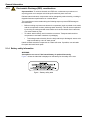
1
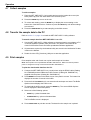
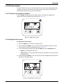
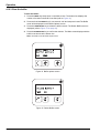
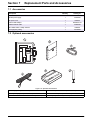
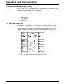
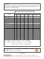
701230
MET ONE HHPC-2
Handheld Airborne Particle Counter
USER MANUAL
May 2008, Edition 3
701230
MET ONE HHPC-2
Handheld Airborne Particle Counter
USER MANUAL
May 2008, Edition 3
© Hach Ultra Analytics, Inc., 2008. All rights reserved. Printed in the U.S.A.
Table of Contents
Section 1 Specifications .................................................................................................................... 5
Section 2 General Information ......................................................................................................... 7
2.1 Safety information ........................................................................................................................ 7
2.1.1 Use of hazard information................................................................................................... 7
2.1.2 Precautionary labels ........................................................................................................... 7
2.1.3 Electrostatic Discharge (ESD) considerations .................................................................... 8
2.1.4 Battery safety information ................................................................................................... 8
2.2 General product information ........................................................................................................ 9
Section 3 Installation........................................................................................................................ 11
3.1 Unpack the instrument ............................................................................................................... 11
3.2 Installation guidelines for MET ONE HHPC-2............................................................................ 12
3.3 Mechanical installation............................................................................................................... 12
3.3.1 Install the isokinetic probe................................................................................................. 12
3.3.2 Install the intake hose barb ............................................................................................... 12
3.3.3 Install the zero count filter ................................................................................................. 13
3.3.4 Connect the AC/DC power supply .................................................................................... 14
Section 4 Operation .......................................................................................................................... 15
4.1 Install the MET ONE HHPC–2 utility software ........................................................................... 15
4.2 Start up ...................................................................................................................................... 15
4.3 Display and keypad.................................................................................................................... 15
4.3.1 Keypad.............................................................................................................................. 16
4.3.2 Screens............................................................................................................................. 17
4.4 Configuration setup.................................................................................................................... 17
4.5 Select custom settings ............................................................................................................... 17
4.5.1 Set the date and time........................................................................................................ 17
4.5.2 Select the count mode ...................................................................................................... 18
4.5.3 Set the sample units and volume...................................................................................... 19
4.5.3.1 Rate mode................................................................................................................ 19
4.5.3.2 Concentration or totalize mode ................................................................................ 19
4.5.4 Set the contrast................................................................................................................. 20
4.6 Counter operation ...................................................................................................................... 21
4.6.1 Verify the MET ONE HHPC–2 with a zero count filter ...................................................... 21
4.7 Collect samples.......................................................................................................................... 22
4.8 Transfer the sample data to the PC ........................................................................................... 22
4.9 Print samples ............................................................................................................................. 22
4.10 Storing samples ....................................................................................................................... 23
4.10.1 Determine the number of samples .................................................................................. 23
4.10.2 Display buffer records ..................................................................................................... 23
4.10.3 Clear the buffer ............................................................................................................... 24
Section 5 Maintenance .................................................................................................................... 25
5.1 Battery maintenance .................................................................................................................. 25
5.1.1 Charge a drained battery .................................................................................................. 25
5.2 Calibrate the MET ONE HHPC–2 .............................................................................................. 25
Section 6 Troubleshooting ............................................................................................................. 27
6.1 Problems and recommendations ............................................................................................... 27
Section 7 Replacement Parts and Accessories ......................................................................... 29
7.1 Accessories................................................................................................................................ 29
7.2 Optional accessories.................................................................................................................. 29
Section 8 Service Contact Information ........................................................................................ 31
3
Table of Contents
Section 9 Limited Warranty .............................................................................................................32
Section 10 Certification....................................................................................................................33
Appendix A Data Communications ...............................................................................................35
Index ......................................................................................................................................................37
4
Section 1
Specifications
Specifications are subject to change without notice.
General
Dimensions (W x L x H)
114.30 mm x 209.60 mm x 57.20 mm (4.5" x 8.25" x 2.25")
Weight
1.0 kg (2.2 lb)
Number of size channels
2
Standard
IAQ
0.3, 0.5 µm
0.3, 1.0 µm
0.5, 5.0 µm
Custom
0.3 to 20 µm available
Flow rate
0.1 cfm (2.83 L/min)
Light source
Laser diode; index guided (26,000 MTBF at 25 °C)
Calibration
PSL particles in air (NIST traceable)
Counting efficiency
50% at 0.3 µm; 100% for particles > 0.45 µm (per JIS B9921:1997)
Zero count
1 count/5 minute (per JIS B9921:1997)
Coincidence loss
5% at 2,000,000 particles per ft3
Relative humidity
20% to 90%, non-condensing
Temperature
± 3 °C, 10 °C to 40 °C (50 °F to 104 °F)
Data storage
100 sample records (rotating buffer)
Data recorded
Counts, calibration error
Display
LCD, 4 x 16 character display
Alarms
Low battery, calibration error
Count modes
Concentration, totalize, audio
Delay time
0 to 24 hours
Sample inlet
Isokinetic probe
Interface
RS232 through RJ45
Vacuum source
Internal pump, flow controlled
Housing
Injection molded plastic
Power
AC Adapter, 12 VDC at 2.5 A, 90 to 250 VAC, 50 to 60 Hz
Rechargeable battery
NiMH, 4.8 V at 4.5 Ah; replaceable
Recharge time
2 hours
Continuous Operating Time
8 hours
Standards
CE, JIS B9921: 1997
Environment
Operating temperature
10 °C to 40 °C (50 °F to 104 °F)
Operating relative humidity
20% to 90%, non-condensing
Storage temperature
–10 °C to 50 °C (14 °F to 122 °F)
Storage relative humidity
Up to 90%, non-condensing
Compliance
JIS B 9921–1997—Light Scattering Automatic Particle Counter
Standards
Federal Standard 209E—Standard Practice for Defining Size Calibration,
Resolution and Counting Accuracy of an Air-Borne Particle Counter Using
Near-Monodispersed Spherical Particulate Material.
5
Specifications
6
Section 2
General Information
2.1 Safety information
Read this entire manual before unpacking, setting up or operating this equipment. Pay
attention to all danger and caution statements. Failure to do so could result in serious
injury to the operator or damage to the equipment.
To make sure that the protection provided by this equipment is not impaired, do not use
or install this equipment in any manner other than that specified in this manual.
2.1.1 Use of hazard information
DANGER
Indicates a potentially or imminently hazardous situation which, if not avoided, will
result in death or serious injury.
WARNING
Indicates a potentially or imminently hazardous situation which, if not avoided,
could result in death or serious injury.
CAUTION
Indicates a potentially hazardous situation that can result in minor or
moderate injury.
Important Note: Indicates a situation which, if not avoided, can cause damage to the
instrument. Information that requires special emphasis.
Note: Information that supplements points in the main text.
2.1.2 Precautionary labels
Read all labels and tags attached to the instrument. Personal injury or damage to the
instrument could occur if not observed. A symbol, if noted on the instrument, will be
included with a danger or caution statement in the manual.
This symbol, if noted on the instrument, references the instruction manual for operation and/or safety information.
Electrical equipment marked with this symbol cannot be disposed of in European public disposal systems after
12 August of 2005. In conformity with European local and national regulations (EU Directive 2002/96/EC),
European electrical equipment users must now return old or end-of life equipment to the Producer for disposal at no
charge to the user.
Note: To return for recycling, contact the equipment producer or supplier for instructions on how to return end-of-life
equipment, producer-supplied electrical accessories and all auxiliary items for proper disposal.
This symbol, when noted on a product enclosure or barrier, indicates that a risk of electrical shock and/or
electrocution exists.
This symbol, if noted on the product, indicates the need for protective eye wear.
This symbol, when noted on the product, identifies the location of a fuse or current limiting device.
This symbol indicates a laser device is used in the equipment.
This symbol, when noted on the product, indicated the presence of devices sensitive to Electro-static Discharge
(ESD) and indicated that care must be taken to prevent damage with the equipment.
7
General Information
2.1.3
Electrostatic Discharge (ESD) considerations
Important Note: To minimize hazards and ESD risks, maintenance procedures not
requiring power to the analyzer should be performed with power removed.
Delicate internal electronic components can be damaged by static electricity, resulting in
degraded instrument performance or eventual failure.
The manufacturer recommends taking the following steps to prevent ESD damage to
the instrument:
•
Before touching any instrument electronic components (such as printed circuit cards
and the components on them) discharge static electricity. This can be accomplished
by touching an earth-grounded metal surface such as the chassis of an instrument,
or a metal conduit or pipe.
•
To reduce static build-up, avoid excessive movement. Transport static-sensitive
components in anti-static containers or packaging.
•
To discharge static electricity from the body and keep it discharged, wear a wrist
strap connected by a wire to earth ground.
Handle all static-sensitive components in a static-safe area. If possible, use anti-static
floor pads and work bench pads.
2.1.4 Battery safety information
WARNING
An explosion can occur if the internal battery is replaced incorrectly.
Figure 1 shows the label that is displayed on the battery for the safety of the user.
Figure 1 Battery safety label
8
General Information
2.2 General product information
The MET ONE Handheld Airborne Particle Counter–2 (HHPC–2) (refer to Figure 2) is a
portable instrument that measures, counts, stores and reports airborne particulates. The
standard MET ONE HHPC–2 holds 100 samples in the memory. The data records
include date, time, counts, sample labels, volume, alarm flags, temperature and relative
humidity. The user can download the data to a personal computer (PC) using the
included interface cable and software. The internal battery powers up the MET ONE
HHPC–2 when mobile or when connected to the AC power adapter.
Note: The AC power adapter provided with the unit is used for extended or stationary sampling.
The MET ONE HHPC–2 is used:
•
To monitor the air quality in clean-rooms
•
To monitor the air quality in manufacturing processes
•
To monitor the air quality in pharmaceutical production
Figure 2 MET ONE HHPC–2
1
Front view of the MET ONE HHPC–2
1
Bottom view of the MET ONE HHPC–2
2
Back view of the MET ONE HHPC–2
9
10
Section 3
Installation
DANGER
Only qualified personnel should conduct the tasks described in this section of
the manual.
3.1 Unpack the instrument
Remove the components from the shipping container and inspect for damage. Verify that
all the items listed in Figure 3 are included. If any items are missing or damaged, contact
the manufacturer or sales representative.
Retain the original packaging materials. Use the original packaging material to store or
ship the instrument to protect against damage during storage or transportation.
Figure 3 List of packaged items
1
MET ONE HHPC–2
6
6¼”–OD high purity tubing (VP792002)
2
Zero count filter
7
MET ONE HHPC–2 Utility software (CS200025)
3
Intake nozzle, 1/8” hose barb (MP000026–01)
8
RS232 modular cable (VP894408)
4
Black cap/Intake nozzle cover
9
RJ45 to DB9 adaptor (SA000070–01)
5
US power cord (CS200025)
10 AC/DC power supply (VP624005)
11
Installation
3.2 Installation guidelines for MET ONE HHPC-2
The MET ONE HHPC–2 is ready to use when shipped and has default configuration
settings. Refer to the following general guidelines during installation.
1. Lift the MET ONE HHPC–2 from the shipping container or the carrying case and
place it on a flat surface.
2. Remove the layer of protective plastic from the LCD screen.
3. Remove the isokinetic probe cover (black plastic cap) before the startup of the MET
ONE HHPC–2.
Note: The pump and other internal electrical components will be damaged if the cap is left on.
Note: The battery is charged before shipping, but may need to be charged before operation (refer to
section 6.1 on page 27 for more information).
3.3 Mechanical installation
The MET ONE HHPC–2 is shipped with two different intake devices:
•
Isokinetic probe
•
Intake hose barb
Important Note: Do not use a wrench to connect or disconnect the intake nozzle or
isokinetic probe. Only finger-tighten the connection.
3.3.1 Install the isokinetic probe
The isokinetic probe (refer to Figure 4 on page 13) is used to sample ambient air
samples. The isokinetic probe is pre-installed and ready for use as soon as the MET ONE
HHPC–2 is unpacked. To install the isokinetic probe:
1. Attach the isokinetic probe to the intake nozzle on the MET ONE HHPC–2 by turning
the isokinetic probe to the right.
2. Remove the black plastic cap attached to the isokinetic probe.
Note: Make sure that the cap is attached to the isokinetic probe when the probe is not in use.
The cap protects the MET ONE HHPC–2 from debris and contamination.
To sample areas that are difficult to reach, connect longer tubing to the isokinetic probe
with a hose barb end.
Note: Use a maximum of four feet of high purity or approved tubing only. Incorrect size or type of
tubing will affect the sample accuracy.
3.3.2 Install the intake hose barb
The intake hose barb (refer to Figure 4 on page 13) is connected to the MET ONE
HHPC–2 for zero counting and purging or to sample areas that are difficult to reach.
To install the intake hose barb:
1. Unscrew the isokinetic probe from the MET ONE HHPC–2.
2. Attach the hose barb.
3. Remove the protective cap from the intake hose barb.
12
Installation
Figure 4 Isokinetic probe with tubing and zero count filter
1
Hose barb fitting
3
Tubing
2
Isokinetic probe
4
MET ONE HHPC–2
3.3.3 Install the zero count filter
In a clean-room application, the zero count filter (refer to Figure 3 on page 11, item 2)
verifies if the MET ONE HHPC–2 is not counting electrical noise signals from internal
components and is not subject to external interference. In indoor air quality and other
applications, the zero count filter cleans out the sensor immediately after a high
concentration sampling.
To connect the zero count filter:
1. Remove the isokinetic probe from the MET ONE HHPC–2.
2. Attach the intake hose barb (MP000026–01).
3. Secure the high purity tubing (VP792002) to the hose barb.
4. Secure the opposite end of the tubing to the zero count filter (VP212808).
Note: Make sure that the arrow of airflow direction or the indicator on the zero count filter points
towards the tubing.
13
Installation
3.3.4 Connect the AC/DC power supply
Important Note: Do not use a power supply unit that does not supply the required voltage
and charging current (polarity) to operate the MET ONE HHPC–2.
To connect the external power supply:
1. Turn off power to the MET ONE HHPC–2 unit.
2. Plug one end of the power cord into the external power supply and the other end into
an electrical wall receptacle.
3. Plug the external power supply jack into the MET ONE HHPC–2 power port (refer to
Figure 5, item 1).
Figure 5 Location of power port
1
14
I/O port
2
Power port
Section 4
Operation
4.1 Install the MET ONE HHPC–2 utility software
To install the MET ONE HHPC–2 utility software:
1. Connect the MET ONE HHPC–2 to the communications port on the PC using the
RS232 modular cable (VP894408).
2. Connect the DB9 to the RJ45 converter (SA000070–01).
3. Insert the MET ONE HHPC–2 utility software (CSVDownloadUtility) diskette into the
drive.
4. Copy CSVDownloadUtility.exe and CSVDownloadUtility.ini from the diskette to a
working directory on the PC. If the communications port to be used is other than
Com1, open CSVDownloadUtility.ini and change Port=Com1 to Port=ComX (where X
represents the number of the port to use.)
5. To open the utility software, double-click the CSVDownloadUtility.exe file. The
CSVDownloadUtility window is displayed (refer to Figure 6 on page 15).
6. Follow the instructions in the Readme.txt file on the diskette to install the software.
Figure 6 MET ONE HHPC-2 Utility (CSVDownloadUtility) window
4.2 Start up
Press and hold the POWER button on the right of the display of the MET ONE HHPC–2 to
turn on the unit. When the MET ONE HHPC–2 is powered on, the MET ONE Opening
screen is displayed briefly followed by the Main screen.
4.3 Display and keypad
The MET ONE HHPC–2 features a Liquid Crystal Display (LCD) with a keypad at the
bottom. Power on the unit and the MET ONE Opening screen displays briefly, followed by
the Main screen.
Note: If the MET ONE HHPC–2 does not power up, double-check the AC connection or the battery
power. To charge the battery, refer to section 5.1 on page 25.
15
Operation
4.3.1 Keypad
Figure 7 shows the display of the Main screen of MET ONE HHPC–2. Table 1 on page
16 provides information about the keypad available at the bottom of the screen and the
various function keys.
Figure 7 MET ONE HHPC–2 Main screen display
1
Display screen
3
MODE key
2
POWER key
4
START/STOP key
Table 1 Indicators and key features or functions
Key
16
Name
Description
START/STOP
Starts and stops a sample
MODE
Selects modes and saves data when the unit is counting
POWER
Toggles the power on and off
Operation
4.3.2 Screens
Press the corresponding button from the keypad at the bottom of the LCD to invoke the
following screens:
•
Main screen—The main screen displays:
•
Channel sizes
•
Particle counts (only displayed when counting or in Buffer mode)
•
Status of the counting process (Run or Wait)
•
Battery charge indicator (amount of charge remaining in the battery, refer to Table
4 on page 25)
•
Select mode screen
•
Select volume screen
•
Buffer count and Buffer options screen
•
Display buffer screen
•
Contrast screen
•
Date and Clock setup screen
4.4 Configuration setup
Once the MET ONE HHPC–2 is unpacked and connected to the appropriate intake
device, use the default settings to conduct a 1-minute count cycle. Download the data to
a PC and print the results.
To perform a 1-minute count cycle:
1. Remove the isokinetic probe cover (black plastic cap).
2. Press and hold the POWER key until the MET ONE HHPC–2 sounds two beeps and
turns on.
3. Press START/STOP on the Main screen to start counting. The count cycle begins and
the bottom line of display changes from “Wait” to “Run”. After one minute, the count
cycle ends and the display clears.
Note: The results are saved automatically in the print buffer.
Refer to section 4.8 on page 22 to transfer the data to a PC and print the results.
4.5 Select custom settings
To choose a setting, select an option that is displayed at the bottom of the Main screen
when the MODE key is pressed, then use the START/STOP and MODE keys to scroll
through the options or save selections.
4.5.1 Set the date and time
To set the date and time:
1. Press the MODE key six times on the Main screen. The bottom line displays the time
and date.
2. Press and hold the MODE key for one second until two beeps are heard. The Date
and Time screen is displayed with the date selected.
3. Use the MODE key to select the digit. The cursor moves to the next digit.
17
Operation
4. When the date, month, year or time is set, press the START/STOP key to change the
numbers for that field.
5. To select another unit of time, press the MODE key to select the next field. Press the
START/STOP key to change the numbers.
6. When the date and time are set, press and hold the MODE key for one second to
save the new setting and return to the Main screen.
4.5.2 Select the count mode
To select the count mode:
1. Press the MODE key once on the Main screen. Refer to Table 2 on page 18 for the
different modes available. The bottom line displays the current mode (refer to
Figure 8 on page 18).
2. Press the START/STOP or the MODE key.
3. When the required mode is displayed on the screen, press and hold the MODE key
for one second to save the new setting and return to the Main screen.
Figure 8 Select mode screen
Table 2 Count modes
Mode
Description
Sample unit
Concentration
The Concentration mode is useful for taking a quick snapshot of
airborne particulate samples, especially in areas where
particulate levels are unknown and may exceed the operating
levels of the counter. The MET ONE HHPC–2 estimates count
per cubic foot or liter depending on the volume selected. The unit
updates the results by calculating completed sample counts and
volume compared to the balance of volume remaining.
Volume size
Rate
In the Rate mode, counting is continuous. The sliding average of
ten samples is displayed.
Volume unit
Totalize
In the Totalize mode, number of counts are displayed as they
accumulate, until the end of the sample. When the sample is
completed, the record is stored and the value is displayed on the
screen until the next sample is started.
Volume size
18
Operation
4.5.3 Set the sample units and volume
Sample volume may be measured in either liters or cubic feet. The volume size can
range from 0.01 cubic foot or 1 liter up to 1 cubic foot or 28.3 liters.
4.5.3.1 Rate mode
In the Rate mode, the unit of the sample volume is selected.
To select the unit of sample volume:
1. Make sure the unit is set to Rate mode as described in section 4.5.2 on page 18.
2. Press the MODE key twice on the Main screen. The bottom line displays the current
unit settings as shown in Figure 9.
3. Press and hold the MODE key for one second, until two beeps are heard. The Select
Units screen displays the selected units.
4. To select the units, press either the START/STOP key for cubic feet or the MODE key
for liters.
5. Press and hold the MODE key for one second to save the new setting and return to
the Main screen. The units selected appear on the right column of the Main screen.
Figure 9 Select Units screen
4.5.3.2 Concentration or totalize mode
In the Totalize or Concentration modes, the volume size is selected.
To select the volume size in concentration or totalize mode:
1. Make sure the unit is set to Concentration or Totalize mode as described in
section 4.5.2 on page 18.
2. Press the MODE key twice on the Main screen. The bottom line displays the current
volume setting.
3. Press and hold the MODE key for one second, until two beeps are heard. The Select
Volume screen displays the selected volume as shown in Figure 10 on page 20.
4. To review the sample volume settings available, press either the START/STOP key or
the MODE key. Refer to Table 3 for sample volume choices.
19
Operation
Table 3 Sample volume settings
Volume
Time for sample (MM:SS)
0.01 cubic feet
00:06
28.3 cubic liters
10:00
10.0 cubic liters
03:53
2.83 cubic liters
01:00
1.0 cubic liter
00:21
1.0 cubic foot
10:00
0.10 cubic foot
01:00
5. Once the required volume choice is displayed, press and hold the MODE key for one
second to save the new setting and return to the Main screen. The volume selected
is displayed in the right column of the Main screen.
Figure 10 Select volume screen
4.5.4 Set the contrast
To set the contrast:
1. Press the MODE key five times on the Main screen.
2. The bottom line displays the current contrast.
3. Press and hold the MODE key for one second, until two beeps are heard. The
Program Contrast screen is displayed (refer to Figure 11).
4. Press the START/STOP key to increase the contrast. Press and hold the MODE key to
decrease the contrast.
5. Once the required contrast is achieved, press and hold the MODE key for one second
to save the new setting and return to the Main screen.
20
Operation
Figure 11 Program contrast screen
4.6 Counter operation
Once the MET ONE HHPC–2 unit configuration is set:
•
Use the zero count to verify the operation of the filter.
•
Collect air samples, transfer them to a computer for further analysis and print them.
•
Review the number of samples in the print buffer and, if needed, clear the print buffer.
4.6.1 Verify the MET ONE HHPC–2 with a zero count filter
Make sure that the instrument is not falsely counting due to sensor leakage, internal or
external electrical interference or any other reason before the unit is used for monitoring
or verifying clean-room condition.
Clean the MET ONE HHPC–2 using the zero count filter before storage or shipment.
Purge the MET ONE HHPC–2 with a zero count filter before using it in a clean-room or a
clean manufacturing environment. This process meets the Japanese Industrial Standard
B9221-1997 (JIS).
To verify the unit with a zero count filter:
1. Remove the isokinetic probe from the unit.
2. Attach the intake hose barb (MP000026-01).
3. Secure the high purity tubing (VP 792002) to the hose barb.
4. Secure the opposite end of the tubing to the zero count filter (VP212808). Make sure
the arrow on the filter is pointing away from the tubing. Now the unit is ready to purge
and zero count.
5. Operate the unit for approximately 15 minutes.
6. Verify that the data on the display is:
•
Not more than one particle greater than 0.3 µm in five minutes on average, or
•
Not more than one particle per 0.5 cubic foot.
Note: Initial counts are typically from particles shedding from components used for zero
counting. The zero count process or guidelines set forth by applicable industry standard(s) is
continued.
7. Remove the zero count filter and attach the isokinetic probe to resume normal
operations.
21
Operation
4.7 Collect samples
To collect samples:
1. Place the MET ONE HHPC–2 unit upright and remove the intake valve cover (the
black plastic cap) from the intake barb or the isokinetic probe.
2. Press the POWER key to turn on the unit.
3. To review each setting, press the MODE key to display the current setting on the
bottom line of the Main screen. Continue to press the MODE key until all the settings
are reviewed.
4. Press the START/STOP key to start sampling on the Main screen.
4.8 Transfer the sample data to the PC
Refer to section 3. on page 14 to install the MET ONE HHPC–2 Utility software.
To transfer sample data from MET ONE HHPC–2 to a PC:
1. Use the MET ONE HHPC–2 Utility software to download particle count data to a PC
in comma separated variable (CSV) file format. The particle count data can be
viewed in Microsoft® Excel® and other spreadsheet software applications.
2. All parameters required by the download utility are stored in the initialization file that
is also on the diskette.
3. Double click the CSV_Download_Utility.exe to start the application.
4.9 Print samples
Print samples at the end of each run or print each sample as it is taken.
Note: Not all printers are compatible with the MET ONE HHPC–2. Make sure that the portable
printer is configured correctly to function with the MET ONE HHPC–2.
To print the downloaded data from the PC:
1. Connect the MET ONE HHPC–2 to a serial printer using the RS232 cable (Catalog
No. VP894408) and the DB9 to the RJ45 convertor (Catalog No. SA000091-01)
supplied with the printer (Catalog No. SA000094-01).
2. Press MODE three times on the Main screen of the particle counter. The bottom line
displays the number of records in the buffer.
3. Press and hold the MODE key for one second until two beeps are heard. The Buffer
Options screen displays the buffer count.
4. To download the buffer records, press the MODE key. The second Buffer Options
screen displays the download options.
5. Select one of the following options:
•
MODE key—prints formatted data
•
START/STOP key—prints unformatted data
The Print Buffer screen is displayed.
6. Press START/STOP to print the records. The data from the sample run is printed.
22
Operation
4.10 Storing samples
The MET ONE HHPC–2 stores each measurement in a 100-record rotating buffer. Data
is stored in a ‘first in first out’ order. Thus, when record 101 is saved, the first record is
automatically deleted, leaving a total of 100 records.
4.10.1 Determine the number of samples
Press the MODE key three times on the Main screen. The bottom line displays the
number of records in the Buff Count field (refer to Figure 12).
Figure 12 Buffer count screen
4.10.2 Display buffer records
To display the buffer records:
1. Press the MODE key four times on the Main screen.
2. Press and hold the MODE key for one second until two beeps are heard. The most
recent record in the buffer is displayed (refer to Figure 13).
3. To review the buffer records, press either the MODE key or the START/STOP key:
•
MODE key—displays the first record
•
START/STOP key—scrolls backwards through the records from the most recent to
the oldest record
4. Press and hold the MODE key for one second to exit the Stored Buffer Record screen
and return to the Main screen.
Figure 13 Stored buffer record screen
23
Operation
4.10.3 Clear the buffer
To clear the buffer:
1. Press the MODE key three times on the Main screen. The bottom line displays the
number of records in the Buff Count field (refer to Figure 14).
2. Press and hold the MODE key for one second, until two beeps are heard.The Buffer
count will be displayed on the Buffer Options screen.
3. Press the START/STOP key to delete the buffer records. The Delete Buffer screen is
displayed (refer to Figure 15 on page 24).
4. Press the START/STOP key to confirm the deletion. The Main screen displays with the
buffer count shown at the bottom line.
Note: The buffer count should be equal to zero.
Figure 14 Buffer options screen
Figure 15 Delete Buffer screen
24
Section 5
Maintenance
DANGER
Only qualified personnel should conduct the tasks described in this section of the
manual. MET ONE
5.1 Battery maintenance
The battery status light indicates the relative battery charge status, described in Table 4.
The power supply provided with the instrument serves as battery charger and a direct
power source. Connect the power supply for continuous and long-term sampling.
Table 4 Battery status indicator
Light
Charge mode
Steady green
Fast charge
Flashing green
Maintenance charging mode
Red
Battery is defective and needs to be replaced
No light
Battery is fully charged
To charge the battery:
1. Connect the external power supply (refer to section 3.3.4 on page 14).
2. Turn on the MET ONE HHPC–2.
3. Remove the power supply when no light is seen.
5.1.1 Charge a drained battery
To charge a drained battery:
1. Attach the external power supply to the MET ONE HHPC–2 unit.
2. Wait for five minutes. Turn on the MET ONE HHPC–2.
3. Leave the unit attached to the power supply until the battery charging indicator light
turns off.
5.2 Calibrate the MET ONE HHPC–2
Return the MET ONE HHPC–2 to the manufacturer annually for recalibration to comply
with JIS B9921–1989 standards. The calibration date is displayed on the manufacturer
decal on the back of the MET ONE HHPC–2. Refer to Section 8 on page 31 for MET
ONE HHPC–2 return procedures.
25
Maintenance
26
Section 6
Troubleshooting
6.1 Problems and recommendations
Table 5 lists the problems, reasons and the recommended actions that occur while using
MET ONE HHPC–2.
Table 5 Troubleshooting procedures
Symptom
MET ONE HHPC–2 does not
zero count.
The MET ONE HHPC–2 does not
turn on when the POWER key is
pressed.
MET ONE HHPC–2 unit does not
charge.
Unable to download data in the
buffer.
Unable to print data in the buffer.
MET ONE HHPC–2 display
shows the message, “CAL ALM.”
Cause
Solution
Zero count filter or
hose barb is not
properly attached to
the unit.
Attach the filter or hose barb.
Internal air leak.
Contact the customer service center for repair.
Cell contamination by
excessive dust
exposure.
Return the unit to a factory authorized service center.
The battery voltage too
low.
Connect external power supply to MET ONE HHPC–2 for
operation and charging. Then, turn on the power again.
Connections to MET
ONE HHPC–2 unit is
proper.
Disconnect the power jack from the unit and the power cord
from the AC power source (wall receptacle). Disconnect the
cord/plug from the power supply and reconnect the cord/plug to
the power supply firmly. Restore all connections to the unit and
power source. If the problem persists, contact the customer
service center for repair.
No records in buffer
Make sure there are records in the buffer.
Communication
parameter are not set.
Make sure that the communication parameters of the computer
are set to 9600 baud, 8 data bits, no parity, 1 stop bit.
The connections are
not proper
Check the connections between the MET ONE HHPC–2 and
the computer.
No records in buffer
Make sure that there are records in the buffer.
Communication
parameter are not set
Make sure that the communication parameters of the printer are
set to 9600 baud, 8 data bits, no parity, 1 stop bit.
The connections are
not proper
Make sure that the connections between the MET ONE
HHPC–2 and the printer.
The cell is
contaminated.
Connect the zero count filter and program the MET ONE
HHPC–2 to run for at least five minutes.
If the problem persists, contact the customer service center for
repair.
27
Troubleshooting
28
Section 7
Replacement Parts and Accessories
7.1 Accessories
Description
Intake nozzle,
1/8”
hose barb
AC/DC power supply
Quantity
Catalog no.
1
MP000026–01
1
VP624005
US power cord
1
VP23501
RJ45 to DB9 adapter
1
SA000070–01
RS232 modular cable
1
VP894408
MET ONE HHPC–2 Utility software
1
CS00025
6¼” high purity tubing
1
VP792002
7.2 Optional accessories
Figure 16 Optional accessories
1
Carrying case (SA000089–01)
4
Isokinetic probe, hose barb (MP000120–01)
2
Vinyl carrying case (SA000249–01)
5
Serial thermal printer (SA000094–01)
3
RS232 serial interface extension cable (EP096010)
6
European power cord (VP625300)
29
Replacement Parts and Accessories
30
Section 8
Service Contact Information
U.S.A. customers
By Telephone:
(541) 472-6500
6:30 a.m. to 5:00 p.m. PST
Monday through Friday
By Fax:
(541) 474-7414
By Mail:
Hach Ultra
481 California Avenue
Grants Pass, Oregon 97526
Email:
[email protected]
Website:
www.hachultra.com
International customers
By Telephone:
41 22 594 64 00
By Fax:
41 22 594 64 99
By Mail:
Hach Ultra
Service Department
6, route de Compois, C.P. 212,
CH-1222 Vésenaz, Geneva, Switzerland
Website:
www.hachultra.com
Information required
•
Your name
•
Model number
•
Your phone number
•
Serial number
•
Your company name
•
Comment or question
•
Your fax number
31
Section 9
Limited Warranty
Hach Ultra warrants this instrument to be free of defects in materials and workmanship for a period of
one year from the shipping date. If any instrument covered under this warranty proves defective during
this period, Hach Ultra will, at its option either repair the defective part without charge for extra parts and
labor or provide an equivalent replacement in exchange for the defective product.
If any diode covered under this warranty proves defective during this period, Hach Ultra will, at its option,
either repair the defective diode without charge for parts and labor or provide an equivalent replacement
in exchange for the defective product.
To obtain service under this warranty, the customer must notify the nearest Hach Ultra service support
center on or before the expiration of the warranty period and follow their instructions for return of the
defective instrument. The customer is responsible for all costs associated with packaging and
transporting the defective unit to the service support center and must prepay all shipping charges. Hach
Ultra will pay for return shipping if the shipment is to a location within the same country as the service
support center.
This warranty shall not apply to any defect, failure or damage caused by improper use or maintenance or
by inadequate maintenance or care. This warranty shall not apply to damage resulting from attempts by
personnel other than Hach Ultra representatives or factory authorized and trained personnel, to install,
repair or service the instrument; to damage resulting from improper use or connection to incompatible
equipment; or to instruments that have been modified or integrated with other products when the effect
of such modification or integration materially increases the time or difficulty of servicing the instrument.
THIS WARRANTY IS GIVEN BY HACH ULTRA ANALYTICS WITH RESPECT TO THIS INSTRUMENT
IN LIEU OF ANY OTHER WARRANTIES, EXPRESSED OR IMPLIED. HACH ULTRA ANALYTICS
AND ITS VENDORS DISCLAIM ANY IMPLIED WARRANTIES OF MERCHANTABILITY OR FITNESS
FOR A PARTICULAR NON-CONTRACTUAL PURPOSE. HACH ULTRA ANALYTICS’
RESPONSIBILITY TO REPAIR OR REPLACE DEFECTIVE PRODUCTS IS THE SOLE AND
EXCLUSIVE REMEDY PROVIDED TO THE CUSTOMER FOR BREACH OF THIS WARRANTY.
HACH ULTRA ANALYTICS AND ITS VENDORS WILL NOT BE LIABLE FOR ANY INDIRECT,
SPECIAL, INCIDENTAL OR CONSEQUENTIAL DAMAGES EVEN IF HACH ULTRA ANALYTICS OR
ITS VENDORS HAS BEEN GIVEN ADVANCED NOTICE OF THE POSSIBILITY OF SUCH
DAMAGES.
32
Section 10
Certification
33
Certification
34
Appendix A Data Communications
A.1 Remote serial interface (I/O Port)
The MET ONE HHPC–2 comes with an RS232 communications port, an RS232 cable
and an RJ45 connector. The RS232 communications port is used to communicate with a
computer to download data and for remote operation.
The specifications and wire pin-outs for the I/O port are:
•
Baud rate: 9600 baud
•
Data bits: 8 bits
•
Parity: None
•
Stop bits: 1 bit
A.1.1 DB9 serial connection
If the computer or terminal has a 9-pin serial port with a female connector, use the
modular RJ45 to DB9 connector provided along with the RS232 cable. The MET ONE
HHPC–2 is configured as a Data Communication Equipment (DCE), so the use of a
null-modem cable is not required. The cable pin assignments are shown in Figure 17.
Figure 17 Pin layout for the RJ45 to DB9 connector cable
35
36
Index
A
P
accessories, included .............................................. 29
procedures, troubleshooting .................................... 27
B
R
battery safety ............................................................. 8
Replacement Parts .................................................. 29
RJ45 connector ........................................................ 35
C
Certification .............................................................. 33
connections, adjustments .................................. 12, 15
S
D
Safety information ...................................................... 7
specifications, environment ........................................ 5
specifications, general ............................................... 5
Data Communication Equipment (DCE) .................. 35
DB9 serial connection .............................................. 35
U
H
hazard information ..................................................... 7
hose barb ................................................................. 12
Unpack, instrument .................................................. 11
Z
zero count filter ........................................................ 13
I
isokinetic probe ........................................................ 12
37
Electrical equipment marked with this symbol may not be disposed of in European
public disposal systems after 12 August of 2005. In conformity with European local
and national regulations (EU Directive 2002/96/EC), European electrical equipment
users must now return old or end-of life equipment to the Producer for disposal at no
charge to the user. Note: For return for recycling, please contact the equipment
producer or supplier for instructions on how to return end-of-life equipment for proper
disposal. Important document. Retain with product records.
GERMAN Elektrogeräte, die mit diesem Symbol gekennzeichnet sind, dürfen in Europa nach
dem 12. August 2005 nicht mehr über die öffentliche Abfallentsorgung entsorgt werden. In
Übereinstimmung mit lokalen und nationalen europäischen Bestimmungen (EU-Richtlinie
2002/96/EC), müssen Benutzer von Elektrogeräten in Europa ab diesem Zeitpunkt alte bzw. zu
verschrottende Geräte zur Entsorgung kostenfrei an den Hersteller zurückgeben. Hinweis:
Bitte wenden Sie sich an den Hersteller bzw. an den Händler, von dem Sie das Gerät bezogen
haben, um Informationen zur Rückgabe des Altgeräts zur ordnungsgemäßen Entsorgung zu
erhalten. Wichtige Informationen. Bitte zusammen mit den Produktinformationen aufbewahren.
FRENCH A partir du 12 août 2005, il est interdit de mettre au rebut le matériel électrique
marqué de ce symbole par les voies habituelles de déchetterie publique. Conformément à la
réglementation européenne (directive UE 2002/96/EC), les utilisateurs de matériel électrique
en Europe doivent désormais retourner le matériel usé ou périmé au fabricant pour élimination,
sans frais pour l’utilisateur. Remarque : Veuillez vous adresser au fabricant ou au fournisseur
du matériel pour les instructions de retour du matériel usé ou périmé aux fins d’élimination
conforme. Ce document est important. Conservez-le dans le dossier du produit.
ITALIAN Le apparecchiature elettriche con apposto questo simbolo non possono essere
smaltite nelle discariche pubbliche europee successivamente al 12 agosto 2005. In conformità
alle normative europee locali e nazionali (Direttiva UE 2002/96/EC), gli utilizzatori europei di
apparecchiature elettriche devono restituire al produttore le apparecchiature vecchie o a fine
vita per lo smaltimento senza alcun costo a carico dell’utilizzatore. Nota: Per conoscere le
modalità di restituzione delle apparecchiature a fine vita da riciclare, contattare il produttore o il
fornitore dell’apparecchiatura per un corretto smaltimento. Documento importante. Conservare
con la documentazione del prodotto.
DANISH Elektriske apparater, der er mærket med dette symbol, må ikke bortskaffes i
europæiske offentlige affaldssystemer efter den 12. august 2005. I henhold til europæiske
lokale og nationale regler (EU-direktiv 2002/96/EF) skal europæiske brugere af elektriske
apparater nu returnere gamle eller udtjente apparater til producenten med henblik på
bortskaffelse uden omkostninger for brugeren. Bemærk: I forbindelse med returnering til
genbrug skal du kontakte producenten eller leverandøren af apparatet for at få instruktioner
om, hvordan udtjente apparater bortskaffes korrekt. Vigtigt dokument. Opbevares sammen
med produktdokumenterne.
Form No 011229
SWEDISH Elektronikutrustning som är märkt med denna symbol kanske inte kan lämnas in på
europeiska offentliga sopstationer efter 2005-08-12. Enligt europeiska lokala och nationella
föreskrifter (EU-direktiv 2002/96/EC) måste användare av elektronikutrustning i Europa nu
återlämna gammal eller utrangerad utrustning till tillverkaren för kassering utan kostnad för
användaren. Obs! Om du ska återlämna utrustning för återvinning ska du kontakta tillverkaren
av utrustningen eller återförsäljaren för att få anvisningar om hur du återlämnar kasserad
utrustning för att den ska bortskaffas på rätt sätt. Viktigt dokument. Spara tillsammans med
dina produktbeskrivningar.
SPANISH A partir del 12 de agosto de 2005, los equipos eléctricos que lleven este símbolo no
deberán ser desechados en los puntos limpios europeos. De conformidad con las normativas
europeas locales y nacionales (Directiva de la UE 2002/96/EC), a partir de esa fecha, los
usuarios europeos de equipos eléctricos deberán devolver los equipos usados u obsoletos al
fabricante de los mismos para su reciclado, sin coste alguno para el usuario. Nota: Sírvase
ponerse en contacto con el fabricante o proveedor de los equipos para solicitar instrucciones
sobre cómo devolver los equipos obsoletos para su correcto reciclado. Documento importante.
Guardar junto con los registros de los equipos.
DUTCH Elektrische apparatuur die is voorzien van dit symbool mag na 12 augustus 2005 niet
meer worden afgevoerd naar Europese openbare afvalsystemen. Conform Europese lokale en
nationale wetgegeving (EU-richtlijn 2002/96/EC) dienen gebruikers van elektrische apparaten
voortaan hun oude of afgedankte apparatuur kosteloos voor recycling of vernietiging naar de
producent terug te brengen. Nota: Als u apparatuur voor recycling terugbrengt, moet u contact
opnemen met de producent of leverancier voor instructies voor het terugbrengen van de
afgedankte apparatuur voor een juiste verwerking. Belangrijk document. Bewaar het bij de
productpapieren.
POLISH Sprzęt elektryczny oznaczony takim symbolem nie może byćlikwidowany w
europejskich systemach utylizacji po dniu 12 sierpnia 2005. Zgodnie z europejskimi, lokalnymi i
państwowymi przepisami prawa (Dyrektywa Unii Europejskiej 2002/96/EC), użytkownicy
sprzętu elektrycznego w Europie muszą obecnie przekazywać Producentowi stary sprzęt lub
sprzęt po okresie użytkowania do bezpłatnej utylizacji. Uwaga: Aby przekazać sprzęt do
recyklingu, należy zwrócić siędo producenta lub dostawcy sprzętu w celu uzyskania instrukcji
dotyczących procedur przekazywania do utylizacji sprzętu po okresie użytkowania. Ważny
dokument. Zachować z dokumentacją produktu.
PORTUGESE Qualquer equipamento eléctrico que ostente este símbolo não poderá ser
eliminado através dos sistemas públicos europeus de tratamento de resíduos sólidos a partir
de 12 de Agosto de 2005. De acordo com as normas locais e europeias (Directiva Europeia
2002/96/EC), os utilizadores europeus de equipamentos eléctricos deverão agora devolver os
seus equipamentos velhos ou em fim de vida ao produtor para o respectivo tratamento sem
quaisquer custos para o utilizador. Nota: No que toca à devolução para reciclagem, por favor,
contacte o produtor ou fornecedor do equipamento para instruções de devolução de
equipamento em fim de vida para a sua correcta eliminação. Documento importante.
Mantenha junto dos registos do produto.
Form No 011229
Dieses Informationsblatt enthält Angaben, die ausschließlich für den Export dieses Gerätes in die Volksrepublik China
erforderlich sind.
This document contains information which is only required for the export of this instrument into the People’s Republic of China.
Ce document contient les informations nécessaires pour l'exportation d'instruments vers la République Populaire de Chine.
本手册只包含出口到中华人民共和国的・ 器的必要信息。
名称:
Optical Particle Counter with Display
有毒有害物・ 或元素
部件名称
金属(底盘\面板\部件\・ 罩)
印刷电路板 (PCBA)
电・ &电・ &接・ (Wire/Conn)
・ /电机/励磁器 (Pump or Fan)
光学元件 (Optical Comps)
玻璃 (Glass Fuses)
显示器件 (Display)
・
Pb
汞
Hg
・
Cd
六价・
Cr6+
多溴联・
PBB
多溴二・ ・
PBDE
X
X
X
X
X
X
X
O
O
O
O
O
O
X
X
X
X
X
O
O
O
X
O
O
X
O
O
O
O
X
X
X
O
O
O
O
X
X
X
O
O
O
○:表示・ 有毒有害物・ 在・ 部件所有均・ 材料中的含量均在 SJ/T11363-2006 ・ 准・ 定的限量要求以下
X:表示・ 有毒有害物・ 至少在・ 部件的某一均・ 材料中的含量超出 SJ/T11363-2006 ・ 准・ 定的限量要求
至出售之日,本表格已显示上述电子信息产品中哪些零部件可能存在有害物・ 。
除非另外特别的・ 注,此・ 志为・ 对所涉及产品的・ 保使用期・ 志. 某些可更・ 的零部件会有一个不同的・ 保使用期(例
如,电池单元模・ )・ 在其产品上.
此・ 保使用期限只适用于产品是在产品手册中所・ 定的条件下工作.
15
Form 011360
EUROPE: HACH LANGE
HACH LANGE GMBH – Willstätterstraße 11 – 40549 Düsseldorf – Germany – Phone +49(0)211-5288-143 – [email protected]
USA AND REST OF WORLD:
Hach Company – P.O. Box 389 – Loveland – Colorado – 80539-0389 – USA – Phone 800-227-4224 – Fax: 970-669-2932 – [email protected]
Trademarks are property of their respective owners.
Specifications subject to change without notice.