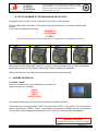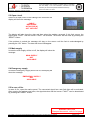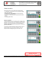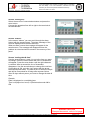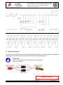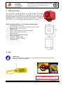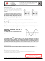
1
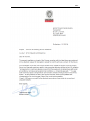
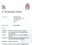
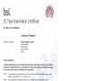
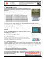
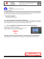
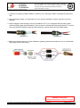
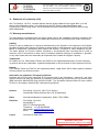
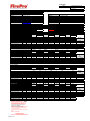
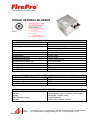
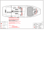
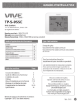
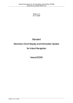
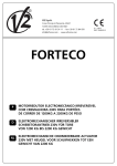
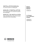
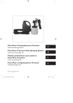
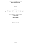
INF.3 Economic Commission for Europe Inland Transport Committee 27 October 2015 Working Party on the Transport of Dangerous Goods Joint Meeting of Experts on the Regulations annexed to the European Agreement concerning the International Carriage of Dangerous Goods by Inland Waterways (ADN) (ADN Safety Committee) Twenty-eighth session Geneva, 25 - 29 January 2016 Item 4 (b) of the provisional agenda Implementation of ADN: Special authorizations, derogations and equivalents Request for a temporary derogation for the tank vessel “Chemgas 851” for the use of a dry aerosol generating fire extinguishing system Transmitted by the Government of the Netherlands I. Introduction 1. In January 2014, the ADN Administrative Committee authorized the competent authority of the Netherlands to issue a trial certificate of approval to the motor tank vessel Chemgas 851 (Sirocco), official ID number 55679 and BV Register number 24521F, type G tanker, as referred to in the ADN, for the use of liquefied natural gas (LNG) as fuel for the propulsion installation. 2. Since then it has come to the attention of the competent authority of the Netherlands that the fire extinguishing agent used on board of the vessel does not comply with 9.3.1.40.2.1 of the Regulations annexed to ADN. The vessel uses a dry aerosol generating fire extinguishing system (FP5700S) which is not listed in the mentioned paragraph. 3. On 24 September 2015 the CCNR issued a recommendation which allows Chemgas 851 (Sirocco), under strict conditions, to use this dry aerosol generating fire extinguishing system as the permanently fixed fire-extinguishing agent in the engine room, the boiler room and the pump room. The decision was based on the technical reports which can be found in the Annex of this document. II. Proposal 4. In accordance with the last sentence of 9.3.1.40.2.1 of the Regulations annexed to the ADN, the Government of the Netherlands requests the Administrative Committee to authorize the competent authority of the Netherlands to allow on board the motor tank vessel Chemgas 851 (Sirocco), official ID number 55679 and BV Register number 24521F, the use of this dry aerosol generating fire extinguishing system as the permanently fixed fire-extinguishing agent mentioned in the paragraph above. 1 INF.3 5. Attached is in Annex I a proposed text for a possible derogation, and - CCNR Recommendation - Letter from Bureau Veritas to Dutch inspection body ILT - Type Examination Certificate - Production Quality Assurance Certificate - Information, Instruction and User Manual - FirePro calculation of the Sirocco - FirePro technical information FP5700S - Overview of Sirocco INF.3 Annex I Decision of the ADN Administrative Committee relating to the tank vessel “Chemgas 851” Derogation No. xx/2016 of xx January 2016 The competent authority of the Netherlands is authorized to issue an addition to the trial certificate of approval of the motor tank vessel Chemgas 851 (Sirocco), official ID number 55679 and BV Register number 24521F, type G tanker as referred to in ADN, for the use of a dry aerosol generating fire extinguishing system (FP5700S). Pursuant to paragraph 1.5.3.2 of the Regulation annexed to ADN, the abovementioned vessel may deviate until 31 December 2018 from the requirement: 1. 9.3.1.40.2.1, Extinguishing agent: The extinguishing agent is not listed in the paragraph. The vessel is equipped with a permanently fixed fire-extinguishing agent of the type dry aerosol generating fire extinguishing system (FP5700S). The Administrative Committee had decided that the use of this dry aerosol generating fire extinguishing system is sufficiently safe if the conditions set by the CCNR are met at all times, and if: 1. All data related to the use of the dry aerosol generating fire extinguishing system (FP5700s) shall be collected by the carrier. The data shall be sent to the competent authority on request. 2. After use of the permanently fixed fire-extinguishing agent, an evaluation report shall be sent to the UNECE secretariat for information of the Administrative Committee, including the operational data and the inspection report by the classification society which classed the vessel. INF.3 ZENTRALKOMMISSION FÜR DIE RHEINSCHIFFFAHRT EMPFEHLUNGEN AN DIE SCHIFFSUNTERSUCHUNGSKOMMISSIONEN ZUR RHEINSCHIFFSUNTERSUCHUNGSORDNUNG EMPFEHLUNG Nr. 26/2015 vom 24. September 2015 Zu § 10.03b Nr. 1 – fest installierte Feuerlöschanlagen in Maschinen-, Kessel- und Pumpenräumen Trockenes aerosolbildendes SBC1 - Löschmittel SIROCCO In Anwendung des § 10.03b Nr. 1 letzter Satz RheinSchUO wird dem Tankmotorschiff „Sirocco“ - einheitliche europäische Schiffsnummer 55679 - unter den nachstehenden Bedingungen zugestanden, in den Maschinenräumen trockenes aerosolbildendes SBC-Löschmittel zu verwenden: 1. § 10.03b Nr. 2, Nr. 3, Nr. 5, Nr. 6 und Nr. 9 finden dementsprechend Anwendung. 2. Das trockene aerosolbildende SBC-Löschmittel ist typgenehmigt gemäß der Richtlinie 96/98/EG des Rates vom 20. Dezember 1996 über Schiffsausrüstung. 3. Jeder zu schützende Raum (Maschinenraum und Bugstrahlruderraum) muss mit einer eigenen Löschanlage ausgestattet werden. 4. Die zu schützenden Räume, in denen sich Gas- oder Zweistoffmotoren befinden, müssen nach den im IGFCode festgelegten Bestimmungen für gassichere Maschinenräume angelegt sein. 5. Das trockene aerosolbildende SBC-Löschmittel wird in speziell dafür vorgesehenen drucklosen Behältern im zu schützenden Raum aufbewahrt. Diese Behälter müssen so angebracht sein, dass das Löschmittel gleichmäßig verteilt wird. Insbesondere muss das Löschmittel auch unter den Flurplatten wirken. 6. Die Inbetriebnahme der Löschanlage muss über eine elektrische Steuerung im Sinne von § 10.03b Nr. 5 Buchstabe c erfolgen. Jeder Behälter wird separat mit der Einrichtung für die Inbetriebnahme verbunden. 7. Beim Auslösen der Löschanlage muss die LNG-Zufuhr zum Motor über das Hauptventil automatisch geschlossen werden. 8. Die Menge an trockenem aerosolbildendem SBC-Löschmittel für den zu schützenden Raum muss mindestens 120 g/m³ des Bruttovolumens des Raums betragen. 9. Die Behälter mit Löschmittel müssen nach 15 Jahren ausgetauscht werden. Die Notstrom-batterien sind spätestens nach sechs Jahren auszutauschen. 10. Diese Empfehlung gilt ausschließlich für die Brandklassen A und B. (Die der Erteilung der Empfehlung zugrundeliegenden technischen Unterlagen sind dem Dokument RV/G (15) 12 zu entnehmen.) *** 1 Solid Bound Compound INF.3 COMMISSION CENTRALE POUR LA NAVIGATION DU RHIN RECOMMANDATIONS AUX COMMISSIONS DE VISITE RELATIVES AU REGLEMENT DE VISITE DES BATEAUX DU RHIN RECOMMANDATION N° 26/2015 du 24 septembre 2015 Ad Article 10.03ter, chiffre 1 - Installations d'extinction fixées à demeure dans les salles des machines, salles de chauffe et chambres des pompes Agent extincteur SBC2 formant un aérosol sec SIROCCO En application de l'article 10.03ter, chiffre 1, dernière phrase, du RVBR, l’automoteur-citerne "Sirocco", numéro européen unique d'identification des bateaux 55679, est autorisé à utiliser dans les salles des machines l’agent extincteur SBC formant un aérosol sec, aux conditions suivantes : 1. L'article 10.03ter, chiffres 2, 3, 5, 6 et 9, est applicable. 2. L'agent extincteur formant un aérosol sec est agréé par type conformément à la Directive 96/98/CE du Conseil du 20 décembre 1996 relative aux équipements marins. 3. Chaque local à protéger (salle des machines et salle du propulseur d’étrave) doit être équipé de sa propre installation d'extinction. 4. Les locaux à protéger, dans lesquels des moteurs à gaz ou bicombustibles sont installés, doivent être conformes aux règles pour les salles des machines protégées contre le gaz telles que fixées par le code IGF. 5. L'agent extincteur SBC formant un aérosol sec est conservé dans des réservoirs non pressurisés spécifiquement prévus à cet effet dans le local à protéger. Ces réservoirs doivent être installés de manière à ce que l’agent extincteur puisse se répartir uniformément. L'agent extincteur doit notamment agir aussi sous le plancher. 6. Le déclenchement de l'installation d'extinction doit se faire au moyen d'un dispositif de commande électrique tel que visé à l'article 10.03ter, chiffre 5, lettre c). Chaque réservoir doit être relié individuellement au dispositif de déclenchement. 7. Lorsque l'installation d’extinction se déclenche, l'alimentation du moteur en GNL doit être arrêtée automatiquement par le biais de la vanne principale. 8. La quantité d'agent extincteur SBC formant un aérosol sec correspondant au local à protéger doit être d’au moins 120 g par m3 de volume brut du local concerné. 9. Les réservoirs contenant l'agent extincteur doivent être remplacés après 15 ans. Les batteries de secours doivent être remplacées après 6 ans au plus tard. 10. La présente recommandation s’applique uniquement aux classes de feu A et B. (Les données techniques tenant lieu de base pour la présente recommandation figurent au document RV/G (15) 12.) *** 2 Solid Bound Compound INF.3 CENTRALE COMMISSIE VOOR DE RIJNVAART AANBEVELINGEN AAN DE COMMISSIES VAN DESKUNDIGEN MET BETREKKINGTOT DE TOEPASSING VAN HET REGLEMENT ONDERZOEK SCHEPEN OP DE RIJN AANBEVELING Nr. 26/2015 van 24 september 2015 Bij Artikel 10.03b, eerste lid - Vast ingebouwde brandblusinstallaties in machinekamers, ketelruimen en pompkamers Droog aerosolvormend SBC3-blusmiddel SIROCCO Voor de toepassing van artikel 10.03b, eerste lid, laatste volzin, van het ROSR, wordt op het motortankschip “Sirocco” - uniek Europees scheepsidentificatienummer 55679 - toegestaan om het droge aerosolvormende SBC-blusmiddel in de machinekamers toe te passen, onder de volgende voorwaarden: 1. Artikel 10.03b, tweede, derde, vijfde, zesde en negende lid moeten in acht worden genomen. 2. Het droge aerosolvormende SBC-blusmiddel is typegoedgekeurd volgens Richtlijn 96/98/EG van de Raad van 20 december 1996 inzake uitrusting van zeeschepen. 3. Iedere te beschermen ruimte (machinekamer en boegschroefruimte) moet met een eigen blusinstallatie worden uitgerust. 4. De te beschermen ruimten waarin gas- of dual-fuelmotoren zijn geïnstalleerd, moeten voldoen aan de regels voor gasveilige machinekamers zoals neergelegd in de IGF-code. 5. Het droge aerosolvormende SBC-blusmiddel wordt in speciaal daarvoor voorziene drukloze reservoirs in de te beschermen ruimte opgeslagen. Deze reservoirs moeten zodanig zijn aangebracht dat het blusmiddel gelijkmatig wordt verdeeld. In het bijzonder moet het blusmiddel ook onder de vloerplaten werkzaam zijn. 6. Het in werking stellen van de blusinstallatie moet via een elektrische besturing als bedoeld in artikel 10.03b, vijfde lid, onderdeel c, geschieden. Ieder reservoir wordt afzonderlijk met de inrichting voor het in werking stellen verbonden. 7. Bij inwerkingtreding van de blusinstallatie moet de LNG-toevoer naar de motor via het hoofdventiel automatisch worden afgesloten. 8. De hoeveelheid droog aerosolvormend SBC-blusmiddel voor de te beschermen ruimte moet ten minste 120 g/m³ van het brutovolume van de ruimte bedragen. 9. De reservoirs met blusmiddel moeten na 15 jaren worden vervangen. De noodstroombatterijen moeten uiterlijk na zes jaren worden vervangen. 10. Deze aanbeveling geldt uitsluitend voor de brandklassen A en B. (De technische bescheiden waarop de aanbeveling is gebaseerd kunnen in document RV/G (15) 12 worden gevonden.) *** 3 Solid Bound Compound INF.3 Information-, Instruction- and User manual FS4Y Marine Panel 24521F BUREAU VERITAS Section ................. Version Date : 02 : 01-01-2014 Examined within the General Conditions of Marine Branch of BUREAU VERITAS in order to check the compliance with the applicable requirements of BV Rules for Inland Navigation Nr 217 Nr 529 ....................................................................................... European Directive 2006/87/EC ....................................................................................... ADN Rules / Recommendation N° 22/2013 ....................................................................................... All particulars not shown on this document are assumed to be as per the requirements of the aforesaid texts, mainly constructional details. Antwerp, 16-Sep-2014 [Electronic document] The plan approval office See Letter TN/DNI/4896/NMA/RCO/LLE Keep this information, instruction and user manual for future use. This manual lapses when revised. The latest version is obtainable from Fire Safety 4 You. This information, instruction and user manual is part of the ASP (Aerosol Standard Procedure). Information, instruction and user manual Version-02 / date 01-01-2014 Copyright© All rights reserved. No part of this publication may be reproduced and/or published by print, photo print, microfilm or any other means without the prior permission of Fire Safety 4 You B.V. If this manual is published under order, see the General Terms and Conditions of Fire Safety 4 You B.V. or the relevant agreement concluded between the parties to this effect for the rights and obligations of customer and contractor. This manual may be given to directly interested parties for perusal. 2014 Fire Safety 4 You B.V. The quality system of Fire Safety 4 You B.V. is accordance with ISO 9001:2008 / BRL-K23003. Fire Safety 4 You B.V.® Marine Panel for activation of FirePro fire extinguishing systems in machinery spaces and pump rooms. This Marine Panel is patented. Before you start. This instruction is a supplement to the FirePro Information-, Instruction- and User manual. This Information, Instruction and User manual is part of the ASP (Aerosol Standard Procedure). For proper installation of the marine panel, the user of this supplement needs to take note of the Information-, Instruction- and User manual. All instructions in this supplement as well as the Information-, Instruction- and User manual need to be followed accurately. Table of contents Section 1.0 2.0 3.0 4.0 5.0 6.0 7.0 8.0 9.0 10.0 11.0 12.0 13.0 Subject Page Marine Panel IMO up to 84 ............................................................................................. 3 Display Marine Panel ...................................................................................................... 3 Connections of the Marine Panel .................................................................................... 3 3.1 Remote control box .................................................................................................. 3 3.2 Potential free contacts .............................................................................................. 3 3.3 Power supply ........................................................................................................... 4 3.4 Remote connection for the signal horn and flash light .............................................. 4 Amount of extinguishers.................................................................................................. 4 Alarm on display ............................................................................................................. 5 5.1 Short circuit .............................................................................................................. 5 5.2 Open circuit .............................................................................................................. 6 5.3 Main supply .............................................................................................................. 6 5.4 Emergency supply.................................................................................................... 6 5.5 In case of fire ........................................................................................................... 6 5.6 Main menu MF-20 .................................................................................................... 7 Activating the fire extinguishers ....................................................................................... 9 Connections in marine panel ........................................................................................... 9 End of line diodes ......................................................................................................... 10 Sounder & Beacon ........................................................................................................ 11 Seal .............................................................................................................................. 11 Induction current ........................................................................................................... 12 Statement of conformity ................................................................................................ 16 Warranty, trademarks and patents ................................................................................ 16 BUREAU VERITAS Stamped document, refer to 1st page Fire Safety 4 You is the authorised Master Dealer of the FirePro fire extinguishing systems Page 2 of 16 Keep this information, instruction and user manual for future use. This manual lapses when revised. The latest version is obtainable from Fire Safety 4 You. This information, instruction and user manual is part of the ASP (Aerosol Standard Procedure). Information, instruction and user manual Version-02 / date 01-01-2014 1. Marine Panel IMO – up to 84 The high quality marine panel is built to activate up to a maximum of 84 FirePro aerosol extinguishers units placed in machinery spaces and pump rooms. The marine panel is built in a stainless steel housing with certified components and is IMO certified. The marine panel can be ordered in different types: - marine panel IMO-4 (to activate up to 4 extinguishing units) - marine panel IMO-6 (to activate up to 6 extinguishing units) - marine panel IMO-8 (to activate up to 8 extinguishing units) - marine panel IMO-12 (to activate up to 12 extinguishing units) - marine panel IMO-16 (to activate up to 16 extinguishing units) - marine panel IMO-20 (to activate up to 20 extinguishing units) marine panel IMO-64 (to activate up to 64 extinguishing units) - marine panel IMO-84 (to activate up to 84 extinguishing units) This marine panel may only be installed by CATTAS (Certified Authorized Technical Technician Aërosol Systems) trained and certified persons. 2. Display Marine Panels On every marine panel there is a display which is connected to the LOGO inside the panel. With this display you can operate the marine panel and read several features. Further on in this manual these will be explained. To show the software version of the control box, press F1 and F4 simultaneously for 1 second. 3. Connections of the Marine Panel: 3.1. Remote control box A remote control box (option) can be connected to the marine panel clamps (see drawing on page 10). The remote control box has the same functionality as the buttons on the marine panel. 3.2. Potential free contacts The marine panel has 2 potential free contacts that can be connected to the XS4 clamps. Both contacts are normally closed contacts. The first potential free contact is for the incoming power supplies. If one of the two supplies is missing, the contact will be open. The second potential free contact is the error indication. If one of the following faults occurs, the contact will be open: - main power supply missing; - emergency power supply missing; - short circuit in the wire of the connecting fire extinguisher; - open circuit in the wire of the connecting fire extinguisher; - door switch detects that the door of the marine panel is open. If a fault occurs, the signal lamp “FAULT” and the buzzer “FAULT” will be activated. The buzzer can be reset by pressing the “RESET” button. If another fault occurs and the previous fault was reset, the buzzer will be activated again. BUREAU VERITAS Stamped document, refer to 1st page Fire Safety 4 You is the authorised Master Dealer of the FirePro fire extinguishing systems Page 3 of 16 Keep this information, instruction and user manual for future use. This manual lapses when revised. The latest version is obtainable from Fire Safety 4 You. This information, instruction and user manual is part of the ASP (Aerosol Standard Procedure). Information, instruction and user manual Version-02 / date 01-01-2014 Please Note The potential free contact cannot be reset. 3.3. Power supply Two separate power supplies (24V) must be connected to the marine panel. A main power supply and emergency power supply are necessary for proper functioning. Wiring from the main power supply and emergency power supply to the marine panel must be flexible 2 x 2.5 mm 2 and fire resistant (E30). If one of the power supplies is missing, the display will indicate this fault. The two possible messages are: - main power not available; - emergency power not available. 3.4. Remote connection for the signal horn and flash light A signal horn and flash light can be connected to the XS3 clamps (see drawing page 6). These signal devices will activate when the door of the marine panel is opened. After opening the marine panel door, the signal devices can be deactivated by pressing the “RESET” button. 4. A: SET UP NUMBER OF EXTINGUISHING UNITS LOGO ON THE DISPLAY! Programming the amount of extinguishers. Press the buttons F2 and F3 on the display simultaneously for at least 5 seconds. The following screen will appear: NUMBER OF ACTUATORS 4 F4 BACK Select the amount of actuators (units) by pressing F1. When the right number is selected press F4. The display will show the voltage measurement of the connected actuators. The measured current is approximately 4mA. So the resistance nor the length of the connected cable have any influence. BUREAU VERITAS Stamped document, refer to 1st page Fire Safety 4 You is the authorised Master Dealer of the FirePro fire extinguishing systems Page 4 of 16 Keep this information, instruction and user manual for future use. This manual lapses when revised. The latest version is obtainable from Fire Safety 4 You. This information, instruction and user manual is part of the ASP (Aerosol Standard Procedure). Version-02 / date 01-01-2014 Information, instruction and user manual B: SET UP NUMBER OF EXTINGUISHING UNITS LOGO! Programming the number of units connected to the LOGO! in the cupboard Press the ESC button and hold it. Then press the (arrow left) button for 3 seconds. Release both buttons. The screen will display the following: NUMBER OF ACTUATORS 4 F4 BACK (the F4 back does not function now and is merely there for aesthetic reasons) Step 1 Step 2 Step 3 Step 4 Now press the ESC button again and hold it. Press the (arrow up) button until you have reached the appropriate number of units. Finally press the OK button to finalize the installation. After a few moments, the display will automatically show the measuring mode. 5. ALARMS ON DISPLAY 5.1 Short circuit If there is a short circuit in the cabling of the connector the display will show the message: SHORT CIRCUIT CABLE ACTUATOR [#] The display will also show the date and time when the problem emerged. If this fault occurs, the signal lamp “FAULT” and the buzzer “FAULT” will activate. The buzzer can be reset by pressing the “RESET” button. If the problem is solved the message will stay on the screen until the fault is acknowledged by pressing the “OK” button. The date and time will disappear. BUREAU VERITAS Stamped document, refer to 1st page Fire Safety 4 You is the authorised Master Dealer of the FirePro fire extinguishing systems Page 5 of 16 Keep this information, instruction and user manual for future use. This manual lapses when revised. The latest version is obtainable from Fire Safety 4 You. This information, instruction and user manual is part of the ASP (Aerosol Standard Procedure). Information, instruction and user manual Version-02 / date 01-01-2014 5.2 Open circuit If there is an open circuit in the cabling of the connector the display will show the message: CABLE BREAKAGE ACTUATOR [#] ACT. WITH OK The display will also show the date and time when the problem emerged. If this fault occurs, the signal lamp “FAULT” and the buzzer “FAULT” will activate. The buzzer can be reset by pressing the “RESET” button. If the problem is solved the message will stay on the screen until the fault is acknowledged by pressing the “OK” button. The date and time will disappear. 5.3 Main supply In case the main supply will be cut off, the display will show the message: MAIN SUPPLY NOT AVAILABLE 5.4 Emergency supply In case the emergency supply will be cut off, the display will show the message: EMERGENCY SUPPLY NOT AVAILABLE 5.5 In case of fire In case of fire, open the marine panel. The connected signal horn and flash light will be activated. After opening the marine panel door, the signal devices and the buzzer “FAULT” can be deactivated by pressing the “RESET” button. BUREAU VERITAS Stamped document, refer to 1st page Fire Safety 4 You is the authorised Master Dealer of the FirePro fire extinguishing systems Page 6 of 16 Keep this information, instruction and user manual for future use. This manual lapses when revised. The latest version is obtainable from Fire Safety 4 You. This information, instruction and user manual is part of the ASP (Aerosol Standard Procedure). Information, instruction and user manual Version-02 / date 01-01-2014 5.6 Main menu MF-20 In the main menu you can select the following items: - F1=actuators, in this screen you can read the voltage input of the actuators. - F2=setting act., in this screen you select the actual amount of connected actuators. - F3=alarms, in this screen you can read out the alarm history. - F4=setting date & time. Screen “actuators” There are three screens for reading out the voltage of the actuators. The first screen is for reading out the first eight actuators. Use the arrow buttons to scroll through the screens. In the last screen you can press the F1 button to go to the main menu. A correctly connected actuator will give about 0.6 volt. A actuator with a short circuit will give about 0 volt. An actuator with a breakage will give more than 5 volt. BUREAU VERITAS Stamped document, refer to 1st page Fire Safety 4 You is the authorised Master Dealer of the FirePro fire extinguishing systems Page 7 of 16 Keep this information, instruction and user manual for future use. This manual lapses when revised. The latest version is obtainable from Fire Safety 4 You. This information, instruction and user manual is part of the ASP (Aerosol Standard Procedure). Information, instruction and user manual Version-02 / date 01-01-2014 Screen “setting act.” Select the amount of connected actuators and press the enter button. Connect the actuators from left to right to the terminals in the switchboard. Screen “alarms” In the screen “alarms” you can scroll through the alarm history with the arrow buttons. The alarm message of the event is displayed with the date and time. When an alarm occurs the message will appear in the actual screen. The message will disappear when the problem is solved and will be stored in the memory of the panel. Screen “setting date & time” Use the arrow buttons (< and >) to go to the item you want to change. Press the enter button and a line of characters will appear. Press the enter button until the right character is reached. After a second the line of characters disappears. Use the arrow buttons to change the next item. If everything is OK, go to the “set” button with the arrow buttons and press enter. The date & time is stored in the plc and will be memorized for 20 days after a power failure. After 20 days without power you have to change the date & time. Remark: Date is displayed as: month/day/year Time is displayed as: hour(0-12)/minutes/seconds AM or PM BUREAU VERITAS Stamped document, refer to 1st page Fire Safety 4 You is the authorised Master Dealer of the FirePro fire extinguishing systems Page 8 of 16 Keep this information, instruction and user manual for future use. This manual lapses when revised. The latest version is obtainable from Fire Safety 4 You. This information, instruction and user manual is part of the ASP (Aerosol Standard Procedure). Information, instruction and user manual Version-02 / date 01-01-2014 6. ACTIVATING THE FIRE EXTINGUISHERS Follow the next steps: 1. open de door of the marine panel by turning the handle on the door a quarter to the right (clockwise); break the seal on the yellow/red rotary switch 2. (see left lower part at the inside of the marine panel); 3. turn the yellow/red rotary switch inside the marine panel to the right (clockwise); 4. the fire extinguishers will be activated. The message will stay on the screen until the fault is acknowledged by pressing the “OK” button. The date and time will disappear. Warning The fire extinguishers can work only once. After activation of the fire extinguishing system you must immediately contact your dealer or the distributer via +31 (0)186-699600 or via [email protected] 7. CONNECTIONS INSIDE THE MARINE PANEL BUREAU VERITAS Stamped document, refer to 1st page Fire Safety 4 You is the authorised Master Dealer of the FirePro fire extinguishing systems Page 9 of 16 Keep this information, instruction and user manual for future use. This manual lapses when revised. The latest version is obtainable from Fire Safety 4 You. This information, instruction and user manual is part of the ASP (Aerosol Standard Procedure). Information, instruction and user manual 8. Version-02 / date 01-01-2014 End of line diodes For the correct measurement of wire break and/or short-circuit, you have to place two diodes between the end of the wire and the activator from the extinguishing unit. Please Note Ask your supplier whether the diodes are already installed. Diode type: 1N5062 BUREAU VERITAS Stamped document, refer to 1st page Fire Safety 4 You is the authorised Master Dealer of the FirePro fire extinguishing systems Page 10 of 16 Keep this information, instruction and user manual for future use. This manual lapses when revised. The latest version is obtainable from Fire Safety 4 You. This information, instruction and user manual is part of the ASP (Aerosol Standard Procedure). Information, instruction and user manual 9. Version-02 / date 01-01-2014 Sounder & Beacon The Nexus-105 sounder & beacon is a high output, low current consumption sounder designed for industrial, fire and marine use. During the tests we did use the Nexus-105 and we recommend the Nexus-105 in combination with our marine panels. The Nexus105 is IP66 i.e. you can install the Nexus at almost any location. Nexus 105 dBA Industrial, Fire and Marine Sounder (Red) IP Rating IP66 / continuous Sound 105 dBA / 1m Version / 64 Tones / see tone table Operating Temp. -25ºC to +70ºC Weight 1.1Kg Quarter turn fasteners for ease of installation First fix, wire to base technology Cable Entries 5 Volume control for greater flexibility Three alarm stages Operating Voltage 10-60V Compliancy EN54-3 TYPE B VDS Approved 10. Seal Please Note Before you handover the installation, be sure that the seal is placed and the seal number is noted in the logbook. BUREAU VERITAS Stamped document, refer to 1st page Fire Safety 4 You is the authorised Master Dealer of the FirePro fire extinguishing systems Page 11 of 16 Keep this information, instruction and user manual for future use. This manual lapses when revised. The latest version is obtainable from Fire Safety 4 You. This information, instruction and user manual is part of the ASP (Aerosol Standard Procedure). Information, instruction and user manual Version-02 / date 01-01-2014 11. Induction current Induction or stray currents can occur aboard ships. This should be taken into account when installing an fire extinguishing system that is controlled by an marine panel so that these types of currents can be prevented from having undesired effects on the system’s functioning. As the mechanisms of induction, coils and magnetic fields are not always clear, the following paragraph contains a short theoretical introduction to the phenomena. Subsequently, there is an explanation as to why they sometimes occur aboard ships, followed by practical tips and pointers concerning the cabling to prevent interference with the system from happening. Introduction Induction is a natural phenomenon whereby the production of an electric current across a conductor moves through a magnetic field or when the conductor is located in a changing magnetic field. If there is a magnetic field in the vicinity of the coil, a physical entity (Phi) flux (magnetic current) arises. Before the magnetic field, the coil had no flux. Since coils do respond well to change, the coil produces an opposite flux that neutralises the first flux. As a result, there is a (induction) current across the coil. At any place where there is a current, a voltage can be measured. Electric current is impossible without a closed circuit. So if a magnet were to be moved back and forth through the coil, there may be (induction) tension between the coil’s connection points, but there will be no electric current. Technical explanation Background information: Magnetic induction Magnetic induction B indicates the strength of the magnetic field, denoted T (tesla). The magnetic induction is strongest at a magnet’s poles and weakest in its centre. Magnetic induction is a vector quantity, i.e. it has a direction. This direction goes from a magnet’s north pole to its south pole. In case of an induction coil, the strength of its magnetic field depends on: the intensity of the electric current through the coil; the number of loops of the coil; the coil’s length; the presence of a core in the coil. Magnetic flux Magnetic flux is a measure for the number of magnetic field lines that run perpendicularly through a surface. Its unit is the weber (Wb). Magnetic flux can be calculated with the formula = Bn·A, where Bn is the component of B perpendicular to the surface and A the surface in m2 through which the field lines run perpendicularly. In other words, the more field lines run through a certain surface, the larger the flux. Flux change arises when: the number of field lines increases, e.g. because a magnet is moved closer to the surface; the surface itself increases, e.g. by extending, increasing the number of field lines. BUREAU VERITAS Stamped document, refer to 1st page Fire Safety 4 You is the authorised Master Dealer of the FirePro fire extinguishing systems Page 12 of 16 Keep this information, instruction and user manual for future use. This manual lapses when revised. The latest version is obtainable from Fire Safety 4 You. This information, instruction and user manual is part of the ASP (Aerosol Standard Procedure). Information, instruction and user manual Version-02 / date 01-01-2014 Electromotive force The electromotive force Vind is the electric current over the inductor’s extremes that arises when the magnetic flux through that coil changes. The adjoining illustrations show that there are few field lines running through the left coil and an increasing number through the right one. This means that if the magnet moves towards the induction coil, the flux through the coil will increase and electromotive force will be produced. The amount of electromotive force produced can be calculated with the formula: , where N is the coil’s number of loops, the change in flux and t the duration of the flux change. The formula shows that there is a high electromotive force when in a coil with a large number of loops there is a large flux change in a short period of time. Determining electromotive force with a flux/time graph. In a graph where flux is plotted against time, the electromotive force can be found in the gradient of the line. That gradient equals . When the line is a curve, as in the graph above, first draw a tangent line at the point in question. Then determine the gradient of the tangent. The product of the number of loops and the tangent is the electromotive force. In the illustration above, the flux change and therefore the electromotive force are largest at points in time 1 and 3. At the points in time 0, 2 and 4 the tangent lines are horizontal, i.e. the electromotive force is zero! Induction current If an electric component, e.g. a light or resistance, is connected to the induction coil where electromotive force is produced, this will lead to an induction current in the inductor. The direction of the induction current The induction current’s direction is such that it produces its own magnetic field that counteracts the change of the external flux. BUREAU VERITAS Stamped document, refer to 1st page Fire Safety 4 You is the authorised Master Dealer of the FirePro fire extinguishing systems Page 13 of 16 Keep this information, instruction and user manual for future use. This manual lapses when revised. The latest version is obtainable from Fire Safety 4 You. This information, instruction and user manual is part of the ASP (Aerosol Standard Procedure). Information, instruction and user manual Version-02 / date 01-01-2014 The magnet nears the induction coil, the external flux increases. In the adjoining illustration the north pole nears the coil. Therefore, the number of field lines directed towards the top left increases. The coil will oppose the change with a current that counteracts the increase of these external field lines. In other words, the coil makes a field that is directed towards the bottom right. According to the right-hand rule, the induction current in the coil’s loop goes from A to B. The negatively charged electrons always move against the current, so an accumulation of negative charge arises at A, i.e. A becomes this voltage source’s negative pole. B becomes the positive pole and therefore has the highest potential. NB. The coil is a voltage source in this instance; in a voltage source, the current always goes from negative to positive, outside the voltage source the current always goes from positive to negative! The magnet moves away from the induction coil, the external flux decreases. If the magnet is now being pulled back, the external flux directed towards the top left diminishes and the coil opposes this changes by producing filed lines towards the top left. The induction current in the coil will then go in the opposite direction from the previous situation, when the magnet neared the coil. The positive and negatives poles reverse. Induction currents aboard ships. Leakage and induction current occur more often aboard ships than on land, due to the fact that ships are usually made of steel and therefore mass can develop quite easily. If an induction current develops in the electric circuit of the fire extinguishing system, this may lead to the undesired activation of that system. Provisions have been made in the design of the marine panel to prevent this from happening. The earth plate for instance, is isolated from the casing. When installing the system, it is of the utmost importance to ensure that external induction currents cannot influence the fire extinguishing system’s electric circuit. This can be realized by strictly following the cabling instructions below. Important cabling instructions Illustration 1. 1. do not place cables in loops and/or coil them up; 2. cut cables properly; 3. lead cables through swivel correctly. BUREAU VERITAS Stamped document, refer to 1st page Fire Safety 4 You is the authorised Master Dealer of the FirePro fire extinguishing systems Page 14 of 16 Keep this information, instruction and user manual for future use. This manual lapses when revised. The latest version is obtainable from Fire Safety 4 You. This information, instruction and user manual is part of the ASP (Aerosol Standard Procedure). Information, instruction and user manual Version-02 / date 01-01-2014 1. coiling up or looping a cable creates an induction coil. Placing the cable in straight lines prevents this. 2. when cutting the cable, it is important not to cut into the insulation in order to prevent (current) leakage. 3. When leading a cable through a swivel (illustrations 2 & 3), it is important that the braid, jacket and/or flexible copper wire (illustration 1) do not come in contact with the (metal) swivel. To ensure that, lead sufficient cable through the swivel and use a shrink sleeve for the coaxial cable. illustration 2 illustration 3 4. Make sure that the bare wire of the diodes are properly protected and cannot come in contact with the casing and/or other wiring. BUREAU VERITAS Stamped document, refer to 1st page Fire Safety 4 You is the authorised Master Dealer of the FirePro fire extinguishing systems Page 15 of 16 Keep this information, instruction and user manual for future use. This manual lapses when revised. The latest version is obtainable from Fire Safety 4 You. This information, instruction and user manual is part of the ASP (Aerosol Standard Procedure). Information, instruction and user manual Version-02 / date 01-01-2014 12. Statement of conformity (II-A) We, Fire Safety 4 You B.V., herewith declare that the product Marine Panel types IMO- up to 84, where to this statement refers, is in conformity to the RS “Rules for the Classification and Construction of Sea-Going Ships” (2010) and EMC directives 89/336/EEG and BRL-23001/03 (by KIWA Nederland). 13. Warranty manufacturer The manufacturer guarantees that the marine panel used in the installation performs consistent with the documentation, provided they are installed and maintained in accordance with these instructions. Liability Except in case of deliberate or conscious recklessness by the Supplier or its employees, the Supplier excludes all liability with respect to financial, consequential or other damage or loss on the User's side based on statements, guarantees (both explicit and implicit), conditions or other obligations by law. The same applies for unusual, indirect, incidental or consequential loss (including loss of profit or revenues, loss of documents or data, costs of substitute products, damage to reputation or goodwill, or any other matter that can reasonably be expected to be outside the Supplier’s power). Trademarks Fire Safety 4 You®, FS4Y Marine Panel® and FirePro® are registered trademarks. All other company or product names are trademarks, registered trademarks or service brands of their respective owners. Patents FS4Y Marine Panel and FirePro® are registered patents. Legal action will be taken against violations of these patents, by whichever name. Information on guidelines / European guidelines Products with the CE-mark mentioned in this manual and in the Information-, Instruction- and User manual comply with both the guideline for stationary extinguishing components on dry aerosol basis (EMC directives 89/336/EEG) and the BRL-K23001. The accredited institute KIWA NV has certified FirePro® in accordance with this BRL (Assessment guideline). Authors : Fire Safety 4 You B.V. (Mr. R.G.C. Reijns) Sundermann Elektrotechniek (Mr. R.A. Sundermann) Basis : International Maritime Organisation, KIWA, TNO, KEMA Publisher : Fire Safety 4 You B.V. Koudenberg 5 4651 JR Steenbergen NB Telephone : +31 (0)186-699600 Home page: www.firesafety4you.com Email : [email protected] Layout : Conforms to NEN-5509 BUREAU VERITAS Stamped document, refer to 1st page Fire Safety 4 You is the authorised Master Dealer of the FirePro fire extinguishing systems Page 16 of 16 Calculation Calculation Sirocco-01 Page 1 of 1 File Calculation method in conformity of the manufacturer / MED - 120 gram m3 Date of calculation 01-4-2014 Certified supplier Address ZIP code Place Country Contact person Telephone number E-mail address IGVAB Landsteinerlaan 46 9728KC Groningen Nederland Wobbe Groefsema 06-37303499 [email protected] Name client Address ZIP code Place Country Contact person Telephone number E-mail address Chemgas Barging S.á.r.l. 53, Avenue Pasteur L-2311 Luxembourg Luxembourg dhr. Tieman Zoer Calculation effective amount per m³ in grams Ship name/no. Sirocco Safety factor IMO (NOT REQUIRED) 1 Room name/no. Engineroom Length To protect m³ Fire Class / m³ Total effect. per m³ A&E Amount of grams Type unit Effective ext. agent per unit Number of units, Class A&E Number of units, Class B Number of units, Class C Number of units, Class F FP-20 12,0 2997,0 2997,0 2997,0 2997,0 FP-40 24,4 1473,9 1473,9 1473,9 1473,9 A&E FP-80 47,2 761,9 761,9 761,9 761,9 NOTE! 299,7 120 120 Width 35.964,00 FP-100 61,0 589,6 589,6 589,6 589,6 For wooden ships use a safety factor of 1,17 1 120 120 Height B FP-200 118,0 304,8 304,8 304,8 304,8 35.964,00 FP-500 330,0 109,0 109,0 109,0 109,0 104,4 120 120,00 Width 12.528,00 FP-100 61,0 205,4 205,4 205,4 205,4 B FP-200 118,0 106,2 106,2 106,2 106,2 B 1 120 120 m³ C FP-1200 756,0 47,6 47,6 47,6 47,6 35.964,00 FP-2000 1.200,0 30,0 30,0 30,0 30,0 F FP-3000 1.830,0 19,7 19,7 19,7 19,7 1 120 120 Height 1 120 120 m³ 12.528,00 FP-500 330,0 38,0 38,0 38,0 38,0 C FP-1200 756,0 16,6 16,6 16,6 16,6 12.528,00 FP-2000 1.200,0 10,4 10,4 10,4 10,4 F FP-3000 1.830,0 6,8 6,8 6,8 6,8 C F Number of units Design Room name/no. Bowthruster Length To protect m³ Fire Class / m³ Total effect. per m³ A&E Amount of grams Type unit Effective ext. agent per unit Number of units, Class A&E Number of units, Class B Number of units, Class C Number of units, Class F FP-20 12,0 1044,0 1044,0 1044,0 1044,0 FP-40 24,4 513,4 513,4 513,4 513,4 A&E FP-80 47,2 265,4 265,4 265,4 265,4 B C F Number of units Design 299,70 120 120 35.964,00 FP-5700 3.363,0 10,7 10,7 10,7 10,7 11 Amount in gram 1.029,0 1.029,0 1.029,0 1.029,0 104,40 120 120 12.528,00 FP-5700 3.363,0 3,7 3,7 3,7 3,7 4 Amount in gram 924,0 924,0 924,0 924,0 Room name/no. To protect m³ Fire Class / m³ Total effect. per m³ Length Amount of grams Type unit Effective ext. agent per unit Number of units, Class A&E Number of units, Class B Number of units, Class C Number of units, Class F FP-20 12,0 0,0 0,0 0,0 0,0 FP-40 24,4 0,0 0,0 0,0 0,0 Width Height m³ 0,00 A&E 120 120,00 B 120 120 C 120 120 F 120 120 A&E FP-80 47,2 0,0 0,0 0,0 0,0 0,00 FP-100 61,0 0,0 0,0 0,0 0,0 B FP-200 118,0 0,0 0,0 0,0 0,0 0,00 FP-500 330,0 0,0 0,0 0,0 0,0 C FP-1200 756,0 0,0 0,0 0,0 0,0 0,00 FP-2000 1.200,0 0,0 0,0 0,0 0,0 F FP-3000 1.830,0 0,0 0,0 0,0 0,0 0,00 FP-5700 3.363,0 0,0 0,0 0,0 0,0 Amount in gram 0,0 0,0 0,0 0,0 Number of units Design Room name/no. To protect m³ Fire Class / m³ Total effect. per m³ Length Amount of grams Type unit Effective ext. agent per unit Number of units, Class A&E Number of units, Class B Number of units, Class C Number of units, Class F Width Height m³ 0,00 A&E 120 120,00 B 120 120 C 120 120 F 120 120 FP-20 12,0 0,0 0,0 0,0 0,0 FP-40 24,4 0,0 0,0 0,0 0,0 A&E FP-80 47,2 0,0 0,0 0,0 0,0 0,00 FP-100 61,0 0,0 0,0 0,0 0,0 B FP-200 118,0 0,0 0,0 0,0 0,0 0,00 FP-500 330,0 0,0 0,0 0,0 0,0 C FP-1200 756,0 0,0 0,0 0,0 0,0 0,00 FP-2000 1.200,0 0,0 0,0 0,0 0,0 F FP-3000 1.830,0 0,0 0,0 0,0 0,0 0,00 FP-5700 3.363,0 0,0 0,0 0,0 0,0 FP-20 0 FP-40 0 FP-80 0 FP-100 0 FP-200 0 FP-500 0 FP-1200 0 FP-2000 0 FP-3000 0 FP-5700 15 Number of units Design Type unit Total Number of units 24521F BUREAU VERITAS Section ................. Examined within the General Conditions of Marine Branch of BUREAU VERITAS in order to check the compliance with the applicable requirements of BV Rules for Inland Navigation NR 217 NR 529 ...................................................................................... European Directive 2006/87/EC ...................................................................................... ADN Rules / Recommendation N° 22/2013 ...................................................................................... All particulars not shown on this document are assumed to be as per the requirements of the aforesaid texts, mainly constructional details. The examination of this document gives rise to remarks in red. Antwerp, 16-Sep-2014 [Electronic document] The plan approval office See Letter TN/DNI/4896/NMA/RCO/LLE Pagina 1 van 1 Amount in gram 0,0 0,0 0,0 0,0 DROGE AEROSOL BLUSSER 24521F BUREAU VERITAS Section ................. Examined within the General Conditions of Marine Branch of BUREAU VERITAS in order to check the compliance with the applicable requirements of BV Rules for Inland Navigation NR217/ NR 529 ...................................................................................... European Directive 2006/87/EC ...................................................................................... ADN Rules / Recommendation N° 22/2013 ...................................................................................... All particulars not shown on this document are assumed to be as per the requirements of the aforesaid texts, mainly constructional details. The examination of this document gives rise to remarks in red. Antwerp, 16-Sep-2014 [Electronic document] The plan approval office See Letter TN/DNI/4896/NMA/RCO/LLE Model Type Activeringsmechanisme Activering Te testen stroomsterkte Gewicht Bruto Gewicht Bruto blusstof Gewicht Netto blusstof Operationele uitstroom tijd Uitstroom opening Uitstoot lengte Afmeting Brandklasse TECHNISCHE INFORMATIE FP-5700 / RVS Cold thermische activering door thermokoord elektrisch (6-32V D/C 0,8A in 3-4 seconden) verwarmingselement 2,3 Ohm weerstand maximaal 5 mA. 26.400 gram 5.700 gram 3.363 gram effectief 15-20 seconden 1 8m 300 mm x 300 mm x 300 mm A, B, C, F TOEPASBAARHEID PER UNIT IN m3 INCL. VEILIGHEIDSFACTOR 1,3 Brandklasse A & E 46,84 Brandklasse B 49,75 Brandklasse C 86,23 Brandklasse F 34,04 Ruimten Vervoer Opslag Mechanische ruimten Industrie Adres Contact TOEPASSINGEN < winkels, kantoor, musea < scheepvaart, trein, container, vrachtwagen < magazijn, archief, loods < machinekamer < technische ruimten, diverse : Fire Safety 4 You B.V. Koudenberg 5 4651JR Steenbergen NB The Netherlands : +31 (0)186-699600 / [email protected] / www.firesafety4you.com 24521F BUREAU VERITAS Section ................. Examined within the General Conditions of Marine Branch of BUREAU VERITAS in order to check the compliance with the applicable requirements of BV Rules for Inland Navigation NR 217, NR 529 ...................................................................................... European Directive 2006/87/EC ...................................................................................... ADN Rules/ Recommendation n°22/2013 ...................................................................................... All particulars not shown on this document are assumed to be as per the requirements of the aforesaid texts, mainly constructional details. The examination of this document gives rise to remarks in red. Antwerp, 16-Sep-2014 [Electronic document] The plan approval office See Letter TN/DNI/4896/NMA/RCO/LLE