1
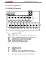
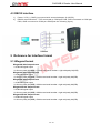
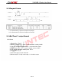
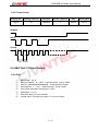
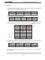
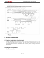
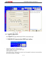
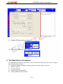
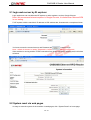
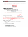
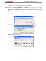
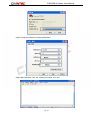
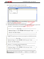
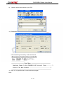
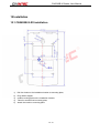
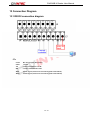
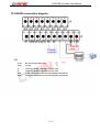
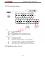
CN56X0B-X Reader User Manual
CN56X0B-X-XX
Access Control Door
Reader
User Manual
Copyright @ 2013
CiVinTec Global Co., Limited
CivinTec Document-Reproduction and Disclosure Prohibited
1 / 47
CN56X0B-X Reader User Manual
Copyright Information
All rights reserved! No part of this publication may be reproduced and stored in any form (electronic,
mechanical, photocopying, recording or other forms) without obtaining written permission from Shenzhen
CiVinTec Global Co., Limited (hereinafter refers to as CIVINTEC). The manual is special written for the
use of this machine of
; therefore we are not responsible for any use of this information as
applied to other devices.
Neither CIVINTEC nor its affiliates shall be liable for damages, losses, costs, or expenses result from:
user or third party’s personal accident, misuse, or abuse of this unit, or unauthorized modifications,
repairs, or alterations to this unit, or failure to strictly comply with CIVINTEC operating and maintenance
instructions.
CIVINTEC shall not be liable for any damages or problems arising from the use of other accessories or
parts other than original CIVINTEC products or CIVINTEC approved products.
Declaration: Other product names used herein are for identification purposes only and the registered
trademark ownership belongs to original companies.
This equipment is intended for use by technical professionals or maintenance personnel.
Trademark Information
is a registered trademark of CiVinTec Global Co., Limited in China and other countries. All
other CIVINTEC trademarks, service marks, domain names, logos, and company names referred to in
this manual are property rights of CIVINTEC or its affiliates. In countries where any of the CIVINTEC
trademarks, service marks, domain names, logos and company names has not been registered,
CIVINTEC claims its ownership for them. Other trademarks referred to in this manual still belong to the
original registered company. You may not use any trademark, service mark, domain name, logo, or
company name of CIVINTEC or other companies referred to in this manual without prior permission from
the owners. You may contact CIVINTEC by visiting its website at http://www.civintec.com, if you have any
questions.
2 / 47
CN56X0B-X Reader User Manual
WARNING
This manual is a necessary part of this product, please read carefully
Keep a record of this text , it may be used for further repair.
This machine is only for recommended uses, do not use for others.
Damaged by improper uses or other uses, manufacturer is not responsible.
Matters Need Attention
Not allowed by the manufacturer or failure to manufacturer's specifications, any changes to the
machine parts and range of use may cause the damage in the direct or indirect
Don’t make machine at extreme temperature and humidity in the environment; Avoid placing it in the
heating equipment, faucet, a humidifier or the fireplace.
Should make the machine avoid contact with a large dust, ammonia, alcohol, diluents or spray type
adhesives etc
Should make machine avoid collisions, fall, etc., which may damage the machine to happen.
Please pay special attention to all labels pasted on the machine.
Should avoid changing the machine’s parts, procedures and other abnormal operation
Note static electricity protective
3 / 47
CN56X0B-X Reader User Manual
Version History
The table below contains the history of changes made to the present document.
Date
Document Version History
V1.0
19-Feb-2013
Original Version
V1.1
28-Feb-2013
Release Version
Version
4 / 47
CN56X0B-X Reader User Manual
Table of Contents
1
Instruction .................................................................................................................................................................. 8
1.1 Instruction .................................................................................................................................................................. 8
1.2 Functions and Features.............................................................................................................................................. 8
1.3 Scope of Suitable Models ........................................................................................................................................... 9
1.4 Applications ............................................................................................................................................................... 9
2
Machine Structure ..................................................................................................................................................... 9
2.1 CN56X0B-X-XX for contactless card interface .......................................................................................................... 9
3
Connector Pin definition ......................................................................................................................................... 11
3.1 CN56X0B-X-XX Connector .......................................................................................................................................11
4
Connection ................................................................................................................................................................ 13
4.1 Wiegand/ABA /Clock&Data interface ...................................................................................................................... 13
4.2 RS485 interface ........................................................................................................................................................ 14
4.3 RS232 interface ........................................................................................................................................................ 15
5
Reference for Interface format ............................................................................................................................... 15
5.1 Wiegand format ........................................................................................................................................................ 15
5.2 Wiegand Frame ........................................................................................................................................................ 16
5.3 ABA Track 1 output format....................................................................................................................................... 16
5.3.1 Data ................................................................................................................................................................... 16
5.3.2 Frame format..................................................................................................................................................... 17
5.4 ABA Tack 2 Output format ....................................................................................................................................... 17
5.4.1 Data ................................................................................................................................................................... 17
5.4.2 Frame format..................................................................................................................................................... 18
5.4.3 LRC portrait redundant checking sum enable method ...................................................................................... 18
5.5 Clock &Data (Europe) format ................................................................................................................................. 18
5.5.1 Description ........................................................................................................................................................ 18
5.5.2 Protocol ............................................................................................................................................................. 19
6
Reader Configuration .............................................................................................................................................. 20
6.1 System Application Development ............................................................................................................................. 20
6.2 Reader Configuration .............................................................................................................................................. 20
6.2.1 Communication port ......................................................................................................................................... 21
5 / 47
CN56X0B-X Reader User Manual
6.2.2 Reader Address ................................................................................................................................................. 22
6.2.3 LED Indicator ................................................................................................................................................... 22
6.2.4 Buzzer Indicator ................................................................................................................................................ 22
6.2.5 Get Firmware Version ....................................................................................................................................... 23
6.2.6 Get Serial Number ............................................................................................................................................ 23
6.2.7 ConfigSet .......................................................................................................................................................... 23
6.2.8 LED&Buzzer Controller(By external) .............................................................................................................. 24
6.3 CN56X0B-X-XX output 7bytes with Wiegand 56 ..................................................................................................... 24
6.4 Format for Wiegand58, Wiegand26, Wiegand32, Wiegand 32e, Wiegand34, Wiegand40, Wiegand42, Wiegand50,
Wiegand56 ..................................................................................................................................................................... 24
6.4.1 Wiegand58 Format ............................................................................................................................................ 24
6.4.2 Wiegand26 Format ............................................................................................................................................ 25
6.4.3 Wiegand32 Format ............................................................................................................................................ 25
6.4.4 Wiegand32e Format .......................................................................................................................................... 25
6.4.5 Wiegand34 Format ............................................................................................................................................ 25
6.4.6 Wiegand40 Format ............................................................................................................................................ 26
6.4.7 Wiegand42 Format ............................................................................................................................................ 26
6.4.8 Wiegand50 Format ............................................................................................................................................ 26
6.4.9 Wiegand56 Format ............................................................................................................................................ 26
7
TCP/IP communication ........................................................................................................................................... 26
8
Get IP address and MAC address........................................................................................................................... 27
9
The Web Server of machine .................................................................................................................................... 28
9.1 login web server by IE explorer ............................................................................................................................... 29
9.2 System reset via web pages ...................................................................................................................................... 29
9.3 IP address reconfiguration ....................................................................................................................................... 30
9.4 MAC address ............................................................................................................................................................ 30
9.5 Module name redefinition ........................................................................................................................................ 31
9.6 Restore factory defaults............................................................................................................................................ 31
9.7 Firmware Upgrade................................................................................................................................................... 31
9.7.1 Firmware Upgrading via web pages ................................................................................................................. 31
9.8 password management ............................................................................................................................................. 33
9.9 Restore factory defaults via keypad.......................................................................................................................... 34
10
TCP/IP communication test and failed solution .................................................................................................... 34
10.1 TCP/IP communication test ................................................................................................................................... 34
10.2 TCP/IP communication failed solution .................................................................................................................. 35
6 / 47
CN56X0B-X Reader User Manual
11
Firmware update by RS232 or RS485(
(only apply to 1C series)
) ..................................................................... 38
12
Installation ................................................................................................................................................................ 42
12.1 CN56X0B-X-XX installation .................................................................................................................................. 42
13 Connection Diagram ................................................................................................................................................... 43
13.1 RS232 connection diagram .................................................................................................................................... 43
13.2 RS485 connection diagram .................................................................................................................................... 44
13.3 TCP connection diagram ....................................................................................................................................... 45
13.4 Typical Connection Diagram ................................................................................................................................. 45
14 Revision history ........................................................................................................................................................... 46
15
Technical support and latest documentation download ....................................................................................... 46
16
Repair and maintenance.......................................................................................................................................... 47
17
Store .......................................................................................................................................................................... 47
7 / 47
CN56X0B-X Reader User Manual
1 Instruction
1.1 Instruction
Optimized to make physical access more secure and smart, CN56X0B access readers
introduce multi-technique to work with all main 13.56Mhz smart cards as DESFire EV1,
Mifare Plus and Sony Felica to enhance security through high encryption and
multi-authentication, and ISO18092 NFC for mobile phone access solution.
1.2 Functions and Features
Functions/ Features
CN56X0B
●High Intelligence, powerful
YES
●Selective cared polling capability(Useful when several cards
are presented )
YES
●Built-in anti-collision(at least one card is detected when
several cards are presented)
YES
●RS232 / RS485 serial interface(Baudrate:9600-115200)
YES
●Support TCP/IP(UDP) communication
YES
●High speed of ISO14443 up to 424kbps
YES
●User controllable bio-color LED, Buzzer
YES
●Backward compatible with all existing versions of CiVinTec’s
13.56MHz products
YES
●Auto answer mode: permanent reading and sending the ID
number Excellent and compact design, can be placed on the
metal surface
●Support high level command of Mifare Plus, DesFire EV1
8 / 47
YES
YES
CN56X0B-X Reader User Manual
1.3 Scope of Suitable Models
This user manual is made for the following list of products: CN56X0BS-X-XX series.
CN5600BS
CN5600B
CN5610B
CN5620B
CN5630B
CN5650B
●
●
●
●
●
●
●
●
●
●
Mifare
Mifare Plus
●
DESFire EV1
●
NFC
●
Felica
●
CN5600B – R/W Mifare secure sector
CN5600BS – R/O Mifare UID
1.4 Applications
1)Access Control
2)Personal Identification
3)E-payment
4)Public Transportation
5)Loyalty
2 Machine Structure
2.1 CN56X0B-X-XX for contactless card interface
CN56X0B-X-XX image:
:(Front View)
CN56X0B-T-0C
CN56X0B-2-0C
CN56X0B-4-0C
CN56X0B-T-1C
CN56X0B-2-1C
CN56X0B-4-1C
9 / 47
CN56X0B-X Reader User Manual
CN56X0B-X-XX
Model
CN5600B
CN5610B
CN5620B
CN5630B
CN5650B
ISO 14443A, Mifare, NFC Forum Specifications
Standard
Read/Write :
Read/Write :
Read/Write :
Read/Write :
Read/Write :
Mifare1K,Mifare4K,
Mifare1K,Mifare4K
Mifare1K,Mifare4K
Mifare1K,Mifare4K
Mifare1K,Mifare4K
Mifare Ultralight
Mifare Ultralight,
Mifare Ultralight,
Mifare Ultralight,
Mifare Ultralight,
Mifare plus
MifareDesfireEV1
Mifare plus
Mifare plus
(2K, 4K, 8K)
Mifare Desfire EV1
Mifare Desfire EV1
(2K, 4K, 8K)
Readable cards
(2K, 4K, 8K)
NFC(type1-type4)
Felica
Operate
13.56 MHz
Frequency
Power Supply
9-24VDC
<150mA
RS232, Wiegand (26,34,42,50,58)/Clock & Data 8,10/ABA1,2
Interface
RS485 Wiegand (26,34,42,50,58)/Clock & Data 8,10/ABA1,2
TCP/IP Wiegand (26,34,42,50,58)/Clock & Data 8,10/ABA1,2
Reading output
Wiegand26/34/42/50/58, Clock & Data 8/10 (3 byte, 5byte, HEX, DEC) , ABA1/2
format
Keypad output
4bit, 8bit, Wiegand26
format
Keypad
3*4 keypad with backlight
Indicators
Blo-color LED and Buzzer controlled by three-wires
Connection
Connector
Reading
50 - 100mm (depending on antenna, transponder)
Distance
Writing Distance
Operating
30 - 70mm (depending on antenna, transponder)
-20°C ~ +60°C / -4°F ~ +160°F
Temperature
Storage
-20°C ~ +60°C / -4°F ~ +160°F
Temperature
Operating
0 ~ 95% relative humidity non-condensing
Humidity
Housing
ABS
Material
Protection Class
IP65, electric epoxy potted for harsh environment
10 / 47
CN56X0B-X Reader User Manual
3 Connector Pin definition
3.1 CN56X0B-X-XX Connector
J3:
9-24V
GND
A/TX
B/RX
WD1
WD0
LED_R1
LED_G1
Buzzer
CP1
DC Power input, DC(9~24V)
Groud
Connect to RS485A of RS485 network and Connect to RS232 TX of PC
Connect to RS485B of RS485 network and Connect to RS232 RX of PC
Data1 signal (connect an external wiegand reader Data1)
Data0 signal (connect an external wiegand reader Data0)
External control Red LED, low level ettection
External control Green LED, low level ettection
External control Buzzer , low level ettection
No connect
NO
COM
NC
N/C
TXTX+
RXRX+
normally open of lock relay
common port of lock relay
normally close of lock relay
No connect
Tranceive Data-; connect to green wire of network cable(pin 6).
Tranceive Data+; connect to white/green wire of network cable(pin 3).
Receive Data-; connect to orange wire of network cable(pin 2).
Receive Data+; connect to white/orange wire of network cable(pin 1)
J4:
11 / 47
CN56X0B-X Reader User Manual
J2:
3.3
SWCKL
GND
SWDIO
DC Power input, DC3.3V
Single bi-directional data pin
Ground
Clock single to target CPU
JP1: This jumper is opening in normal work. When this jumper is shorting before power on, Main unit go
to download user program state (only apply to RS232 interface)
JP2: This jumper is opening in normal work. When this jumper is shorting before power on, Main unit go
to download user program state(apply to RS232 interface and RS485 interface)
12 / 47
CN56X0B-X Reader User Manual
4 Connection
Attention:
1. Please make sure that CN56X0B-X-XX has the same interface format as controller
you are using. If there is need to change interface format, please refer to “6.Reader
Configuration”
2. When connecting to controller, please make sure that controller and reader have
common ground.
4.1 Wiegand/ABA /Clock&Data interface
1)
2)
Power: VCC connect to VCC(+) of controller, and GND connect to GND(-) of controller;
Communication: D1/Clock connect to D1/Clock of controller, D0/Data connect to D0/Data of
controller;
13 / 47
CN56X0B-X Reader User Manual
4.2 RS485 interface
1) Power: VCC(+), GND(-)connected with external adapter (9-24VDC);
2) RS485 communication:
Connect to RS485 Controller:
CN56X0B communication port A connected to the RS485 BUS A, and CN56X0B
communication port B connected to the RS485 BUS B. then RS485 BUS A connected with
the controller’s A communication port, and RS485 BUS B connected with the controller’s B
communication port:
Note: 1) Please refer to the file “Configuration Guidance” to set device address.
2) Please make sure that the controller will use the same communication protocol as
CN56X0B-X-XX. Please refer to the file “Communication Protocol”.
14 / 47
CN56X0B-X Reader User Manual
4.3 RS232 interface
1)
2)
Power: VCC(+), GND(-)connected with external adapter (9-24VDC);
RS232 communication:TXD connected to COM port PIN2, RXD connected to COM port
PIN3, GND connected to COM port PIN5(See the following figure):
5 Reference for Interface format
5.1 Wiegand format
Wiegand26 bits Output format
26 bits Wiegand output
Left even parity bit (MSB) + 24 bits card serial number + right odd parity bit(LSB)
Wiegand34 bits Output format
34 bits Wiegand output
Left even parity bit (MSB) +32 bits card serial number + right odd parity bit(LSB)
Wiegand42 bits Output format
42 bits Wiegand output
Left even parity bit (MSB) +40 bits card serial number + right odd parity bit(LSB)
Wiegand 50 bits Output format
50 bits Wiegand output
Left even parity bit (MSB) +48 bits card serial number + right odd parity bit(LSB)
Wiegand 58 bits Output format
58 bits Wiegand output
Left even parity bit (MSB) +56 bits card serial number + right odd parity bit(LSB)
15 / 47
CN56X0B-X Reader User Manual
5.2 Wiegand Frame
1 is represented by a 50 usec low pulse on DATA1
0 is represented by a 50 usec low pulse on DATA0
5.3 ABA Track 1 output format
5.3.1 Data
1) Starting Bits:Fifty “0”
2) Starting character:B(11010,Lower bit ahead,sort by 1248P)
3) Card ID:0000000000-9999999999(10 bits decimal number)
4) End character:F(11111,lower bit ahead,sort by 1248P)
5) LRC vertical redundant checking sum(BCC)
6) Ending Bits:Fifty “0”
7) Odd check apply on each character
8) All data output: 0 is high level output, 1 is low level output
16 / 47
CN56X0B-X Reader User Manual
5.3.2 Frame format
Starting bits
Starting character
Card info
Ending character
BCC
Ending Bits
fifty “0”
B
10BYTES
F
5BITS
fifty “0”
When sending characters, lower bit is in front of high bit
CARD IN
/DATA
1
0
1
0
1
1
CLOCK
1ms 0.5ms
5.4 ABA Tack 2 Output format
5.4.1 Data
1)
2)
3)
4)
5)
6)
7)
8)
Starting Bits:ten “0”
Starting character:B(11010,Lower bit ahead,sort by 1248P)
Card ID:0000000000-9999999999(10 bits decimal number)
End character:F(11111,lower bit ahead,sort by 1248P)
LRC portrait redundant checking sum(BCC)
Ending Bits:Five “0”
Odd check apply on each character
All data output: 0 is high level output, 1 is low level output
17 / 47
CN56X0B-X Reader User Manual
5.4.2 Frame format
Starting
Bits
Starting
character
Card info
End
character
BCC
Ending
Bits
ten “0”
B
10BYTES
F
5BITS
five “0”
CARD IN
/DATA
1
0
1
0
1
1
CLOCK
1ms 0.5ms
5.4.3 LRC portrait redundant checking sum enable method
LRC character apply following method to calculate: exclude Odd check bit,regulate each bit in
LRC character,it will ensure sum of the bits which is going to be encode at response position is
even number.
B0
B1
B2
B3
P(odd check bit)
Starting character:
1
1
0
1
0
First card character:
1
0
0
0
0
Second
character:
card
0
1
0
0
0
Third
character::
card
1
1
0
0
1
……
……
……
……
……
Ending character:
1
1
1
1
1
LRC character:
0
0
1
0
0
Magstripe data:
……
5.5 Clock &Data (Europe) format
5.5.1 Description
The protocol provides a 3-wire Clock and Data (Europe) interface with a 10 digit BCD or 8 digit
BCD Tag Code. The three wires are defined as Presence, Clock and Data. The Presence line will
indicate the presence of a Tag. The Clock line is used to clock the data on the Data line.
18 / 47
CN56X0B-X Reader User Manual
5.5.2 Protocol
A 10-Digit BCD number transmits the 32 bit Code with a Start and Stop sentinel and Longitudinal
Redundancy Check (LRC) checksum defined as follows:
BCD 0
BCD 1 to 10
BCD 11
BCD 12
Start
32 bit code as BCD
Stop
LRC Checksum
B (Hexadecimal)
NNNNNNNNNN
F (Hexadecimal)
X
Where N = 0 to 9
Each BCD Digit has an odd-parity bit appended:
Bit 0
Bit 1
Bit 2
LSB of BCD
1
0
0
Bit 3
Bit 4
MSB of BCD
Odd Parity
1
1
The LRC checksum is calculated by XOR the BCD Digits including the Start and Stop Sentinel but
excluding the parity bits. The parity of the LRC checksum is also set to odd-parity, For example:
BCD
Binary
Parity
B
1011
0
5
0101
1
7
0111
0
0
0000
1
1
0001
0
9
1001
1
3
0011
1
5
0101
1
1
0001
0
F
1111
1
LRC
1001
1
The 24 bit Code is transmitted by a 8 Digit BCD number with a Start and Stop sentinel and
Longitudinal Redundancy Check (LRC) checksum defined as follows:
BCD 0
BCD 1 to 8
BCD 9
BCD 10
Start
24 bit code as BCD
Stop
LRC Checksum
B (Hexadecimal)
NNNNNNNN
F (Hexadecimal)
X
Where N – 0 to 9
Each BCD Digit is appended with an odd-parity bit as defined above. The LRC checksum is
calculated as above.
The 13-Digit or 11-Digit BCD number is transmitted serially on the Data signal line starting with
BCD-O’s LSB.If a bit is equal to a One the Data signal line is at GND. If the bit is equal to a Zero
19 / 47
CN56X0B-X Reader User Manual
the Data signal line is at Vcc.
The timing of the Clock and Data (Europe) protocol is shown in Figure 2.
6 Reader Configuration
6.1 System Application Development
CivinTec offers API function easy to use further application development, which the user
can directly call API function in program. The user will be recommended to read that
explanation documentation “CNReader SDK” carefully before starting the system
development.
6.2 Reader Configuration
Host Demo overview
20 / 47
CN56X0B-X Reader User Manual
6.2.1 Communication port
The CN56X0X-XX support RS232 and TCP/IP communication type.
1. CN56X0X-XX Communication RS232 port setting
”
▪Select the model from “Select Device”
▪Select “COM?” from “Communication Type
▪Click “Open Port ” button.
▪Baud Rate setting: The function is used to set the speed of serial port communication,
the default setting is 115200bps.
21 / 47
CN56X0B-X Reader User Manual
2. CN56X0X-XX Communication TCP/IP port setting
▪Select the model from “Select Device”
▪Select “TCP/IP” from “Communication Type
▪Remote IP:key in “192.168.1.100”
▪Click “CV_UDPRun ” button
6.2.2 Reader Address
The factory default value “0”is set to system broadcast address.
6.2.3 LED Indicator
The LEDs are used to show the status of power and contactless card.
The Red LED is used to show Power status. The Green LED is used to show
contactless card.
6.2.4 Buzzer Indicator
Buzzer is used to show the contactless card
22 / 47
CN56X0B-X Reader User Manual
Click “Active Buzzer” button, buzzer will beep.
6.2.5 Get Firmware Version
Query Firmware Version.
6.2.6 Get Serial Number
The serial number is a unique number which preset by manufacture.
6.2.7 ConfigSet
Users can realize the auto-read function by using ConfigSet, it supports Mifare, Mifare
Plus and DESFire EV1 total three kinds of cards:
▪Keep the default setting, select “Set Wiegand” button (as red circle shown)
▪Select “SET”, “Run” button
23 / 47
CN56X0B-X Reader User Manual
▪Scan Mifare, Mifare Plus or Mifare EV1 cards , the UID of the card will be read out
automatically, and will be shown in the right window.
6.2.8 LED&Buzzer Controller(By external)
1)
2)
By default, Red LED, Green LED and Buzzer are controlled inside, in this case, Red LED will be
light (until power off ) and Buzzer will be beep (one time) when reader is powered on, also, once
read card successfully, the buzzer will be beep (one time), and green LED will be light (one time).
If “LED&Buzzer Controller(By external)” is checked, Red LED, Green LED and Buzzer are
controlled by three external wires, purple wire controls buzzer, yellow wire controls green LED
and orange wire controls red LED, in this case, once wire (purple, yellow or orange) connect to
low level (GND), features will be enable (Red/Green LED lights, or Buzzer beeps) they will
continues until wire (purple, yellow or orange) is disconnect from GND
6.3 CN56X0B-X-XX output 7bytes with Wiegand 56
The length of Wiegand56 output
1)
2)
CN56X0B-X-XX can completely output 7bytes in Wiegand56 mode without parity bit
For Wiegand58, it output 7bytes with two parity bit.
6.4 Format for Wiegand58, Wiegand26, Wiegand32, Wiegand 32e,
Wiegand34, Wiegand40, Wiegand42, Wiegand50, Wiegand56
6.4.1 Wiegand58 Format
1)
2)
3)
MSB is even parity bit, LSB is odd parity bit.
The bits for calculating even parity are within the first 28 bits, but don’t use the bits from
21 to 24. Actually it uses 24 bits for even parity.
The bits for calculating odd parity are within the last 28 bits, but don’t use the last 8 bits
within these 28 bits. Actually it uses 20 bits for odd parity.
For example:
Data Hex: 00 00 00 89 D4 1B 81
Data Binary:00000000 00000000 00000000 10001001 11010100 00011011 10000001
MSB: 1 from 00000000 00000000 00000000 1000 (Red part don’t use)
LSB: 1 from 1001 11010100 00011011 10000001 (Red part don’t use)
Output: 1 00000000 00000000 00000000 10001001 11010100 00011011 10000001 1
24 / 47
CN56X0B-X Reader User Manual
6.4.2 Wiegand26 Format
1)
2)
3)
MSB is even parity bit, LSB is odd parity bit.
The bits for calculating even parity are within the first 12 bits.
The bits for calculating odd parity are within the last 12 bits.
For example:
Data Hex: D4 1B 81
Data Binary: 11010100 00011011 10000001
MSB: 1 from 11010100 0001
LSB: 0 from 1011 10000001
Output: 1 11010100 00011011 10000001 0
6.4.3 Wiegand32 Format
1)
2)
3)
MSB is even parity bit, LSB is odd parity bit.
The bits for calculating even parity are within the first 15 bits.
The bits for calculating odd parity are within the last 15 bits.
For example:
Data Binary: 001111110101010101010110010000
MSB: 1 from 001111110101010
LSB: 1 from 101010110010000
Output: 1 001111110101010101010110010000 1
6.4.4 Wiegand32e Format
Wiegand32e don’t have odd/even parity bits.
6.4.5 Wiegand34 Format
1)
2)
3)
MSB is even parity bit, LSB is odd parity bit.
The bits for calculating even parity are within the first 16 bits.
The bits for calculating odd parity are within the last 16 bits.
For example:
Data Hex: 89 D4 1B 81
Data Binary: 10001001 11010100 00011011 10000001
MSB: 1 from 10001001 11010100
LSB: 1 from 00011011 10000001
Output:1 10001001 11010100 00011011 10000001 1
25 / 47
CN56X0B-X Reader User Manual
6.4.6 Wiegand40 Format
Wiegand40 don’t have odd/even parity bits.
6.4.7 Wiegand42 Format
1) MSB is even parity bit, LSB is odd parity bit.
2) The bits for calculating even parity are within the first 20 bits.
3) The bits for calculating odd parity are within the last 20 bits.
For example:
Data Hex: 00 89 D4 1B 81
Data Binary: 00000000 10001001 11010100 00011011 10000001
MSB: 0 from 00000000 10001001 1101
LSB: 0 from 0100 00011011 10000001
Output: 0 00000000 10001001 11010100 00011011 10000001 0
6.4.8 Wiegand50 Format
1)
2)
3)
MSB is even parity bit, LSB is odd parity bit.
The bits for calculating even parity are within the first 24 bits.
The bits for calculating odd parity are within the last 24 bits.
For example:
Data Hex:01 00 89 D4 1B 81
Data Binary: 00000001 00000000 10001001 11010100 00011011 10000001
MSB: 0 from 00000001 00000000 10001001
LSB: 1 from 11010100 00011011 10000001
Output: 0 00000001 00000000 10001001 11010100 00011011 10000001 1
6.4.9 Wiegand56 Format
Wiegand56 don’t have odd/even parity bits.
7 TCP/IP communication
1)
Choose “TCP/IP” in Combo box, as follow:
26 / 47
CN56X0B-X Reader User Manual
2)
Set the static IP address for the machine
Note: The IP address default value is 192.168.1.100 which built in machine. It can
be changed by using in your actual network environment. That will be description in
TCP/IP web server part.
3) Click “CV_UDPRun” button
4) The testing of TCP/IP working status. Please click “Get Firmware Version” button
If the TCP/IP communication between the host PC and the machine working well,
the machine will return the firmware version information, show as follow:
Otherwise, you need to check the TCP/IP connection line and host PC TCP/IP
settings, and then repeat step1 to step 4.
5) Stop TCP/IP communication
Click “CV_UDPStop” button
8 Get IP address and MAC address
For easy to get IP address and MAC address, you need access the machine with
RS232/RS485 communication type.
1) Open Host Demo which CIVTEC offered
27 / 47
CN56X0B-X Reader User Manual
2) Choose COM port and open the port
3) Get the IP address and MAC address
9 The Web Server of machine
The CN56X0B-X-XX built in a web server, so you can access the web server via host PC, it support
some main functions as follow:
1) Get/Set IP address, sub MASK, Gate Way, firmware version, module name etc.
2) Reset the machine
3) Firmware Upgrade
4) Restore factory default settings
5) Change password for the account
28 / 47
CN56X0B-X Reader User Manual
9.1 login web server by IE explorer
Login web server can use Microsoft IE explorer or other explorer, such as Google Chrome.
Note: We recommend internet explorer is Google Chrome, it is better than Microsoft IE8
in our testing.
Fill IE explorer with the machine’s IP address at URL address bar, illustrate with a example as follow:
You have to enter the correct Account and Password after click
button to login
Note:default of Account is “admin”,Password is “cn5630b”(modifiable login password)
If the machine is running and the TCP/IP connection form host to machine is working well, it will show
as below:
9.2 System reset via web pages
It’s easy to reset the system of the machine via web pages, click “System Reset” on home page.
29 / 47
CN56X0B-X Reader User Manual
After that you can see the system reset page,
Click the “
” button, and then the machine enter in reset mode, it will last several
seconds. After reset completed, you can access the web page again.
9.3 IP address reconfiguration
The machine built in default IP parameters as below:
You can reconfiguration it by you actual network using. Click
button to submit
your changes.
Note1: If the IP parameters changed, the new parameters will be effective after your reset the
machine.
Note2: If the IP address changed, please use the new address to login in the web pages.
9.4 MAC address
Our products which with TCP/IP function have a unique MAC address, it were set in our manufacture
30 / 47
CN56X0B-X Reader User Manual
procedure. Therefore, you no need to change it, because maybe it’ll cause some TCP/IP
communication problems.
Note:Please don’t use the MAC configuration function as follow:
9.5 Module name redefinition
You can change the default module name to others which you like.
Note1:The module name length less than 40 characters.
9.6 Restore factory defaults
Note1: If the load the factory defaults, it will be effective after your reset the machine.
Note2: Please use the default IP address to login the web pages after machine reset completed.
Note3: The factory default IP address is “192.168.1.120”|
9.7 Firmware Upgrade
There has two solutions for upgrading firmware described as below:
9.7.1 Firmware Upgrading via web pages
1)
Log to upgrading web page
Click “
” on home page
Then, enter in upgrading web page, show as follow:
31 / 47
CN56X0B-X Reader User Manual
2)
click “
3)
If the machine in update mode, the green led which on the front of the machine will light on.
Note1: The factory default IP address is “192.168.1.100”|
Login in updating web page
After step2, the normal application program jump to upgrade application which running in
machine , so you need login in again.If login successfully, it will show:
”
If you can’t see the above login page, please refresh the IE explorer, click here “
4)
Key in password
The User ID and password as follow :
User ID: 000000
Password: 000000
After you key in the user ID and password, please click
5)
”
, and then you’ll see:
Choose a bin file to upgrade
Click browser button
to choose a bin file which our company offered.
32 / 47
CN56X0B-X Reader User Manual
And then, click
, wait for about 20 seconds, if the operation of upload successfully, it
will show:
Note: Don’t forget to refresh your IE explorer when you can’t access the demonstration page.
Because of the IE can store the foregoing pages in cache automatically.
9.8 password management
you can click“password management” link change login Password , show as follow
Enter old password and new password and confirm password in below window after click
“Apply changes”Button,
Note:Password length less than 10 characters.
33 / 47
CN56X0B-X Reader User Manual
9.9 Restore factory defaults via keypad
If you don’t want using web page to restore the factory defaults, or you don’t know the IP address, so
can’t access web pages of the machine, you can use the another way to recover it.
1) Make sure the machine in power off status
2) Keep the “#” key in down status, and then power the machine on.
If the restore factory defaults successfully, the green led and the red led which on the front board
of the machine will in flicking status alternately.
3) Reset the machine via power off and power on.
If the operation failed, please repeat Step1 to Step3.
Note: Restore factory set the IP address for 192.168.1.120
10 TCP/IP communication test and failed solution
In network structure, the router is essential. After our product add in the network environment.
You need to test the communication from your host PC to machine. The test procedure as follows:
10.1 TCP/IP communication test
1)
2)
3)
Make sure the connection between host PC and the machine for TCP/IP communication is
created.
Power on the machine
Enter in Dos system window. ( We presume the OS of your host PC come from Microsoft
series.)
34 / 47
CN56X0B-X Reader User Manual
4)
Key in “Ping 192.168.1.100 –t” on command line (This IP address is factory default)
If “Reply from 192.168.1.100: bytes=32 time<1ms TTL=225” indicate the TCP/IP communication is
working well. Otherwise, please go to 10.2
TCP/IP communication failed solution
10.2 TCP/IP communication failed solution
When you ping to machine by 192.168.1.100, but can’t receive the response from the machine, such
as like this:
35 / 47
CN56X0B-X Reader User Manual
1)
Restore factory defaults. Please refer to “9. Restore factory defaults via keypad”
After this step, the machine IP parameters as follows:
2) Delete machine IP information from router table of roter.
Key in “arp –d” or Key in “arp –d XXX-XXX-XXX-XXX”
The “XXX-XXX-XXX-XXX” is current IP address which you know of the machine. If you don’t know
the current IP address, key in “arp –d”
3)
Binding IP address and MAC address in your router.
36 / 47
CN56X0B-X Reader User Manual
Key in “arp –s 192.168.1.100 00-18-0a-03-08-05” on command line
4)
5)
confirm the arp setting
input “arp –a”
If you see “192.168.1.100 00-18-0a-03-08-05 static”, that indicate the setting is successful.
Testing
37 / 47
CN56X0B-X Reader User Manual
In generally, the TCP/IP communication will be working well now.
11 Firmware update by RS232 or RS485(only apply to 1C series)
)
1)
2)
3)
Make sure the RS232/RS485 communication between the machine and the host PC working
well.
Power off the machine if it’s in working status.
Create a Hyperterminal in your host PC.
The following steps show how to create Hyperterminal on Windows XP:
step1: Go to “Run” command line on Win XP .
step2: Key in “HYPERTRM.EXE” on command line, and then click Confirm button
step3: After operation 2, you can see:
Input a “name” which you like, and then go to next step.
step4: Choose a COM port and then go to next step.
38 / 47
CN56X0B-X Reader User Manual
step5: Config the COM port as follow parameters.
step6: After Operation 5 the, the creating is finished. You’ll see:
39 / 47
CN56X0B-X Reader User Manual
step7: Connect to the machine. Click the “Connect” ICON.
By this time, you can communicate with the machine by COM port
4) Press Key “0” on keypad of the machine, and don’t loosen(
(apply to 1C series)
)
(apply to 0C series)
)
or short circuit Jp2(
5) Power on the machine under the Key “0” pressed down.
6) After Waiting several seconds, you would heard a long beep, it indicates enter in upgrade mode
successfully. The HyperTerminal will show like this:
7)
Key in “1” on HyperTerminal to download a new image file to CN56X0B internal flash
8)
After key in “1” , the machine waiting for download mode.
40 / 47
CN56X0B-X Reader User Manual
9)
Choose a bin file which offered by CIVTEC
10) Transmitting
If the transmitting successfully, it will show like this:
11) Input “3” on HyperTerminal to execute the new program.
Note:
41 / 47
CN56X0B-X Reader User Manual
12 Installation
12.1 CN56X0B-X-XX installation
1)
2)
3)
4)
5)
Drill four holes on the Installation location at mounting plate;
Plug rubber stopper;
Install mounting plate on the Installation location;
Twist four screws fixed mounting plate;
Attach the reader to mounting plate.
42 / 47
CN56X0B-X Reader User Manual
13 Connection Diagram
13.1 RS232 connection diagram
J3:
:
9-24V
GND
TX
RX
WD1
WD0
DC Power input, DC(9~24V)
Groud
Connect to RS232 TX of PC
Connect to RS232 RX of PC
Data1 signal (connect an external wiegand reader Data1)
Data0 signal (connect an external wiegand reader Data0)
43 / 47
CN56X0B-X Reader User Manual
13.2 RS485 connection diagram
J3:
:
9-24V
GND
A
B
WD1
WD0
DC Power input, DC(9~24V)
Groud
Connect to RS485A of RS485 network of PC
Connect to RS485B of RS485 network of PC
Data1 signal (connect an external wiegand reader Data1)
Data0 signal (connect an external wiegand reader Data0)
44 / 47
CN56X0B-X Reader User Manual
13.3 TCP connection diagram
J3:
9-24V
GND
WD1
WD0
DC Power input, DC(9~24V)
Groud
Data1 signal (connect an external wiegand reader Data1)
Data0 signal (connect an external wiegand reader Data0)
NO
COM
TXTX+
RXRX+
normally open of lock relay
common port of lock relay
Tranceive Data-; connect to green wire of network cable(pin 6).
Tranceive Data+; connect to white/green wire of network cable(pin 3).
Receive Data-; connect to orange wire of network cable(pin 2).
Receive Data+; connect to white/orange wire of network cable(pin 1)
J4:
13.4 Typical Connection Diagram
45 / 47
CN56X0B-X Reader User Manual
[Note:]
The Lock Device have been set as Relay output, which support contact output only; the external
power source is required; the corresponding cable must suit to the working current of selected
components
14 Revision history
V1.0 First Version
15 Technical support and latest documentation download
We have professionals to provide prompt, comprehensive technical support. If you have any
technical questions,please contact [email protected].
Latest documentation download is provided in “My Community” on our website using your authorized
login and password. Section “Support” is for your download of all latest technical documentation. The
link
46 / 47
CN56X0B-X Reader User Manual
16 Repair and maintenance
Attention:
Only professional personnel can do repair work, and users should ensure the power off and make
power plug in the monitoring range before any repair or maintenance.
For the correct use and prolong the service life, it is necessary for users to do regular repair and
maintenance according to the specifications, or both the operation and reliability of the machine will
be affected.
Keep the machine and working area clean, avoid dust into the machine.
Avoid machine used in extreme low or high temperature environment.
Avoid all kinds of harmful gases, inflammable, explosive and corrosive chemicals, and should be
far away from strong electromagnetic field.
Avoid machine’s operation procedures changed and other abnormal operations.
17 Store
Put the products in the original packaging box when users want to store them, and general storage
period is six months. Warehouse environment temperature should be-10 ~ + 40, relative humidity
30% ~ 80%; No harmful gases, inflammable, explosive and corrosive chemicals existed, and must
be away from strong electromagnetic field.
47 / 47


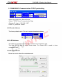


![PIN & 13.56MHz [MIFARE] Contactless Smart Card](http://vs1.manualzilla.com/store/data/005813586_1-ab1687ddb78fed02f4038390c7a52377-150x150.png)