1
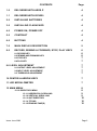
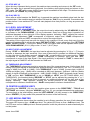
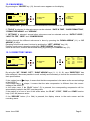
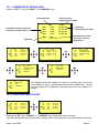
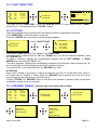
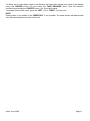
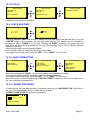
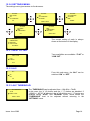
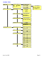
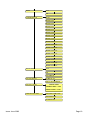
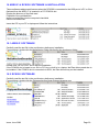
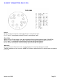
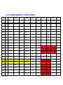
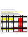
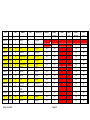
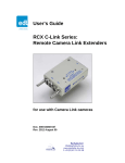
NAGRA ARES-P / RCX220
MANUAL
Version: June 2003
WARNING: The ARES-P/RCX220 has a built-in charger (charge current = 100
mA). NiCd or Ni-Metal-Hydride cells can be used.
WHEN USING THE EXTERNAL POWER SUPPLY, CHECK THE SWITCH
POSITION INSIDE THE BATTERY COMPARTIMENT BEFORE INSTALLING
DRY CELLS.
PN 2019 600 150
Issue: June 2003
Page 1
CONTENTS
Page
1.0
DELIVERED WITH ARES-P
4
1.1
DELIVERED WITH RCX220
4
2.0
INSTALLING BATTERIES
4
3.0
INSTALLING FLASHCARD
4
4.0
POWER ON, POWER OFF
4
5.0
CONTRAST
4
6.0
BUTTONS
4
7.0
MAIN DISPLAY DESCRIPTION
5
8.0
RECORD, REWIND & FORWARD, STOP, PLAY KEYS
6
6
6
7
7
8.1 RECORD KEY
8.2 REWIND AND FORWARD KEY
8.3 STOP KEY
8.4 PLAY KEY
9.0 LEVEL ADJUSTMENT
9.1 OUTPUT LEVEL ADJUSTMENT
9.2 INPUT LEVEL ADJUSTMENT
9.3 THRESHOLD ADJUSTMENT
7
7
7
7
10 CENTER & ARROW KEYS
7
11 LED MODULOMETER
7
12 MAIN MENU
8
8
9
9
10
10
10
12.1.0 DIRECTORY MENU
12.1.1 HORIZONTAL SCROLLING
12.1.2 VERTICAL SCROLLING
12.1.3 QUIT DIRECTORY
12.1.4 TITLING
12.1.5 ERASING TAKE(S)
Issue: June 2003
Page 2
CONTENTS
12.2.0 TOOLS
12.2.1 DATE AND TIME
12.2.2 CARD FORMATTING
12.2.3 FORMAT REPAIRING
12.2.4 VERSION
12.3.0 SETTINGS MENU
12.3.1 INPUT FILTER
12.3.2 ALC
12.3.3 ALC THRESHOLD
12.3.4 ALC SPEED
12.3.5 BEEP
12.3.6 COMPRESSION
12.3.7 BACKLIGHT
12.3.8 OUTPUT MODE
12.3.9 OUTPUT LEVEL
12.3.10 SECOND RECORD KEY
Page
12
12
12
12
13
14
14
14
14
15
15
15
15
15
16
16
13 LOCKING THE SETTINGS
16
14 AUTO POWER OFF
16
15 MESSAGES
17
16 SOFTWARE UPDATE
17
17 DIFFERENCE ARES-P/RCX220
17
18 MENU TREE
18
19 ARES-P & RCX220 SOFTWARE & INSTALLATION
19.1 ARES-P SOFTWARE
19.2 RCX220 SOFTWARE
20
20
20
20 INPUT CONNECTOR, DIN 12 PIN
22
21 FLASH CARDS COMPATIBILITY LINEAR AND STRATA
23
22 FLASH CARDS COMPATIBILITY ATA AND COMPACT ATA
24
23 SAFETY/COMPLIANCE
26
Issue: June 2003
Page 3
1.0 DELIVERED WITH ARES -P.
5 dry cells “AA”, 1 DIN connector 12 pin, 1 carrying strap, 1 user manual.
1.1 DELIVERED WITH RCX220.
5 dry cells “AA”, 1 DIN connector 12 pin, 1 carrying strap, 1 user manual, 1 USB cable, 1 CDR with
npRuntime (RCX220 driver),RcxLoad and Xtrack software.
2.0 INSTALLING BATTERIES.
To open the machine, push the button on the right side. Inside the battery compartment, push down
the black button and remove the inner cover.
Install the 5 “AA” cells and put the inner cover back on.
Important note:
Verify the position of the little switch inside the battery compartment.
In the OFF position, the charger circuitry is not activated and if an external power supply is connected,
the machine will run from external supply and not from the batteries.
In the ON position, the NiCd or Ni- Metal-Hydride cells will be continuously charged with a current of
100mA. This corresponds to a slow charge rate. (charge cycle: 10 to 12 hours). Charging does not
stop automatically.
3.0 INSTALLING FLASHCARD.
Open the machine and insert the flashcard until the eject button is pushed fully out. The software
version 1.20 and higher permits to use linear flash cards and ATA cards.
4.0 POWER ON, POWER OFF.
Press the “POWER ON” button (1) for 1 second and the machine switches on. To switch “OFF” the
machine push the same button again for 1 second.
Attention: the machine can not be switched OFF during RECORD.
5.0 CONTRAST.
If the display contrast is not set properly at power on, adjust step by step with the “RIGHT” or “LEFT”
arrow keys (12 or 10) to increase or decrease accordingly. The contrast setting is not saved in the
memory.
6.0 BUTTONS.
1
2
3
4
5
6
7
8
9
10
11
12
13
Power ON / OFF
+ 2 bis Record key
Rewind, skip backwards key
Stop key
Play key
Forward, skip forwards key
Reducing input sensitivity or playback level key
Increasing input sensitivity or playback level key
Up arrow key or increasing output level key
Contrast or left arrow key
Down arrow key or reducing output level key
Contrast or right arrow key
Other menu or execute key
Issue: June 2003
2 bis
1
9
10
8
13
2
12
11
3
4
7
5
6
Page 4
7.0 MAIN DISPLAY DESCRIPTION.
Attention: At power on, the display below is shown, but without the level bargraph indications on the
right side. This bargraph appears when the “+” or “-“ button (8 or 7) is pressed. It disappears after a
few seconds, this to obtain a better overview during record or play.
Input level indication for
Left and Right channel
Headroom indicator
Input level
1
2
Status of the ARES-P
STOP, PLAY, REC, FWD, RWD
-21
-9
Battery status
+9
IN
007
0:00
Level adjustment
- 20DB
Take number and position
in minutes and seconds
Status of the flashcard
0
Level setting
Stop or play position
on the flashcard
12 TAKES
R:
8:08
LOW BATTERY
Total number of recorded takes
Messages
Remaining time on the card
in minutes and seconds
Status of the ARES-P
“STOP”
“RECORD”
“PLAY”
“SEARCH FORWARD”
“SEARCH BACKWARD”
ARES- P is in STAND BY mode
ARES- P is in RECORD mode
ARES- P is in PLAY mode
ARES- P is playing fast forwards
ARES- P is playing fast backwards
Take number and position in minutes and seconds
This is the physical playback position. The example shows that playback will start at the beginning of
take 7 (0 minutes, 0 seconds).
Stop or play position on the flashcard
The marker shows the exact playback position, take 7 at 0 minutes, 0 seconds.
Status of the flashcard
The full length of the bargraph corresponds to the total memory of the inserted flashcard. The black
area shows how much memory was already used for recording. The clear area shows the remaining
memory.
Total number of recorded takes
This area shows the total number of takes already recorded on the flashcard.
Remaining time on the card in minutes and seconds
This indicates how much recording time is left on the card. In this example, it shows 8 minutes, 8
seconds. If the bit-rate is changed, it will automatically be adapted. Example 8:08 if 128kb/s was set, it
will become 16:16 if the bit-rate was changed to 64kb/s.
Input level indication for Left and Right channel
In the stereo mode, bargraph 1 corresponds to the left channel and 2 to the right channel. In mono
mode, both bargraphs indicate the input level. From 0db, the bargraph shows the headroom up to
+9dB. +9dB corresponds to “FF” for the AD converter.
Issue: June 2003
Page 5
Messages
This is the area for any kind of messages, like “LOW BATTERY”, CARD FULL, NO CARD, etc.
A beep in the headphones corresponds to an arrival of a message on the display.
Battery status
When the battery icon is full, it indicates the cells are charged. Full corresponds to a voltage
measurement of 6.28V or higher. Each step corresponds to 0.256V. When the voltage drops below
5V, a beep is heard in the headphones and the message “LOW BATTERY” appears. The machine
switches automatically to below 4.5V. Using Ni Metal Hydride cells (1200 mA ) delivers approximately 3
hours and 15 minutes of autonomy.
Level Adjustment
This bargraph only appears on the screen during the adjustment of the input sensitivity, the output
level or the ALC threshold adjustment. If no adjustment is made it will disappear after a few seconds.
Simultaneously, the level setting in dB’s as well as the kind of adjustment “IN”, “OUT” or “THR” will
appear on the display.
8.0 RECORD (2, 2bis), REWIND (3), STOP (4), PLAY (5), FORWARD (6) KEYS
8.1 RECORD KEY (2, 2bis)
Once the machine is switched ON and a valid card is inserted, to start recording, the “RECORD” key
(2) or (2bis) can be pressed, even if the machine was in “PLAY” mode or is in one of the sub-menus.
The “RECORD” keys will not work if the machine is deleting a take or formatting the card.
If during record the “RECORD” key is pressed again, a new take is automatically created. This
function is used for “MARKING” the audio during record.
During record, the front LED as well as the red LED on the keyboard turns ON.
During record, the “POWER” key is not active.
8.2 REWIND KEY (3) AND FORWARD KEY (6)
These keys have two functions called “SKIP” backwards or forwards and “REWIND” or “FORWARD”.
SKIP.
During “STOP” mode: To jump take by take, pressing briefly on the “<<” or “>>” keys will decrement or
increment the take position.
During “PLAY” mode: To jump to other takes on the card, press twice in quick succession the “<<” to
decrement the take number or press the “>>” to increment the take number.
IMPORTANT: Only takes with the same compression as the current settings of the machine can be
played back using the SKIP buttons. All other takes with a different compression can not be selected.
FORWARD SEARCH.
This function can be executed during the “STOP” or “PLAY” mode. Once the “>>” key is pressed for
more than 0.5 seconds, the ARES-P starts “FORWARD SEARCH” at 4 times nominal speed. The
longer the button is pressed, the search speed increments up to 128 times nominal speed. When the
button is released, the search stops and the ARES- P goes back to its previous function (STOP or
PLAY).
BACKWARD SEARCH.
This function can be executed during the “STOP” or “PLAY” mode. Once the “<<” key is pressed more
than 0.5 seconds, the ARES-P starts “BACKWARD SEARCH” at 4 times nominal speed. The longer
the button is pressed, the search speed increments up to 128 times nominal speed. When the button
is released, the search stops and the ARES- P goes back to its previous function (STOP or PLAY).
Issue: June 2003
Page 6
8.3 STOP KEY (4)
When this key is pressed during record, the machine stops recording and returns to the “EE” mode.
When the same key is pressed during playback, the machine stops playing back and returns to the
“EE” mode. The “EE” mode means that the input signal is available at the output. This button can also
be used as the “PAUSE” key during playback.
8.4 PLAY KEY (5)
When after a record session the “PLAY” key is pressed the machine immediately plays back the last
recorded take. If the machine was just switched ON and the “PLAY” key is pressed, it remembers the
position before it was switched OFF and will start playback from that position, as long as power was
available.
9.0 LEVEL ADJUSTMENT
9.1 OUTPUT LEVEL ADJUSTMENT
During the “STOP” or “RECORD” mode, the output level can be adjusted by the “UP ARROW” (9) key
to increase or the “DOWN ARROW” (11) key to decrease. Once one of those keys is pressed, an
additional bargraph on the right side of the display appears, indicating “OUT”, showing the current
position of the adjustment. “0dB” corresponds to maximum output level, -“59dB” corresponds to
minimum output level and “OFF” corresponds to mute of the output signal.
The setting of the output level can also be stored in the machine in such a way that every time the
machine is switched ON, it will take the same “DEFAULT LEVEL ” output adjustment (See “SETTINGS
MENU, OUTPUT LEVEL ”). During the “PLAY” mode, the output level can be adjusted either by the
“UP & DOWN ARROW” (9 & 11) keys or the “+” and “-“ (8 & 7) keys.
9.2 INPUT LEVEL ADJUSTMENT
During “STOP” or “RECORD”, the input level can be adjusted by pressing the “+” (8) or “-“ (7) keys to
increase or decrease the input sensitivity. Once one of these keys is pressed, an additional bargraph
on the right side of the display appears, indicating “IN”, corresponding to the current setting. “74dB”
corresponds to maximum input gain, “133dB” corresponds to minimum input gain and “OFF”
corresponds to mute of the input signal. If the input sensitivity is adjusted for “74dB”, it means that if
the input signal at 74dB SPL will be recorded at a 0dB level.
9.3 THRESHOLD ADJUSTMENT
The “THRESHOLD” adjustment permits to select the size of the compression zone. It is the lower limit
setting of the zone that will be automatically amplified during a silent period. The “ALC” is working in a
range of 42dB (from 74dB to 116dB). If the “THRESHOLD” is set to 104dB, it means that a signal of
104Db and higher (max. 116dB) will be recorded at 0dB level (between –2dB and –6dB for a stable
signal). A signal of 90dB will be recorded at –14dB (104dB – 90dB). If “ALC” (Automatic Level Control)
is “ON” and the “ALC THRESHOLD” is set to “USING +/- KEYS” (see SETTINGS MENU, ALC
THRESHOLD), the threshold during “RECORD” or “STOP” can be adjusted by pressing the “+” or “-“
(8 or 7) keys. Once one of these keys is pressed, an additional bargraph on the right side of the
display, indicating “THR” appears, showing the current position of the adjustment. “74dB”
corresponds to maximum threshold level, “104dB” corresponds to minimum threshold level.
10 CENTER & ARROW KEYS
By pushing the “CENTER” (13) key, the machine gives access to the “DIRECTORY”, “TOOLS” and
“SETTINGS” sub-menus. Using the “ARROW” keys (9 to 12), you navigate between those sub-menus.
To move back to the initial display, press the “LEFT ARROW” (10) key (except in the “DIRECTORY”
where “CENTER” (13) key needs to be pressed first to return to the sub-menus).
11 LED MODULOMETER
The LED modulometer shows when the machine is set to Stereo operation, the sum of both channels.
The green LED turns on from –21dB input level. The yellow LED turns on from –9dB input level. The
red LED turns on from 0dB input level. Normal operation is with the yellow led on and occasionally the
red led peaks.
Issue: June 2003
Page 7
12.0 MAIN MENU.
By pressing the “CENTER” key (13), the main menu appears on the display.
1
2
-21
-9
0
007
+9
0:00
DIRECTORY
TOOLS
12 TAKES
R:
DIRECTORY
TOOLS
SETTINGS
8:08
The “DIRECTORY” gives access to all the information of the recorded files on the flashcard.
If “TOOLS” is selected, 4 other sub menus can be selected: “DATE & TIME”, “CARD FORMATTING”,
“FORMAT REPAIRING” and “VERSION”.
If “SETTINGS” is selected, several other sub-menus can be selected such as: “OUTPUT LEVEL ”,
“INPUT FILTER”, “BEEP” and “COMPRESSION”.
Scrolling through the different sub-menus is done by pressing the “DOWN ARROW” (11) or “UP
ARROW” (9) keys.
Escaping from the sub-menu’s is done by pushing the “LEFT” ARROW” key (10).
Entering a sub-menu is done by pushing the “RIGHT ARROW” key (12).
Inside a sub-menu, execute the selected setting by pressing the “CENTER” key (13).
12.1.0 DIRECTORY MENU.
1
2
-21
-9
0
001
+9
0:00
DIRECTORY
TOOLS
12 TAKES
R:
000
001
002
003
END
000
0.00
1.25
3.48
4.24
48.32
0.00
12 / 03 / 00
12 / 03 / 00
13 / 03 / 00
13 / 03 / 00
8:08
By using the “UP”, “DOWN”, “LEFT”, “RIGHT ARROW” keys ( 9, 11, 10, 12), once “DIRECTORY” has
been selected, it becomes possible to scroll vertically and horizontaly to view all the recorded files and
their specifications.
If the marker has a
shape, it means that the take compression is the same as the current settings
of the ARES-P.
If the marker has a
shape, it means that the take compression is different from the current
settings of the ARES-P.
In the latter case, if ht e “PLAY” button” (5) is pressed, the corresponding compression will be
automatically loaded in the DSP, and play starts.
If the marker is in front of one of the audio takes, the “PLAY”, “STOP”, “FWD” and “RWD” function
keys (3,4,5 &6) become active.
If the “RECORD” button (2 or 2bis) is pressed, the display returns to the main screen and the
recording starts.
Issue: June 2003
Page 8
12.1.1 HORIZONTAL SCROLLING.
Use the ”LEFT” (10) and “RIGHT” (12) “ARROW” keys.
Current position
inside the selected file
Selected file No
File No 001, length 1minute 25
seconds, recorded March 12, 2000
000
001
002
003
END
002
0.00
1.25
3.48
4.24
48.32
1.30
12 / 03 / 00
12 / 03 / 00
13 / 03 / 00
13 / 03 / 00
Remaining time on the
card at the selected
compression
End of list
000
001
002
003
END
000
0.00
1.25
3.48
4.24
48.32
0.00
12 / 03 / 00
12 / 03 / 00
13 / 03 / 00
13 / 03 / 00
000
001
002
003
END
000
001
002
003
END
000
001
002
003
END
002
3.48
12 / 03 / 00 10 : 41
12 / 03 / 00 10 : 55
13 / 03 / 00 11 : 25
13 / 03 / 00 14 : 19
002
3.48
< NO TITLE >
FOOTBALL GAME IN
< NO TITLE >
ACCIDENT
002
3.48
< NO TITLE >
PARIS
< NO TITLE >
000
001
002
003
END
Format file,
created March 12, 2000
000
001
002
003
END
002
3.48
FORMAT CARD
MPEG 192 / 48 ST.
MPEG 128 / 24 ST.
G.722
002
3.48
< NO TITLE >
GAME IN PARIS
< NO TITLE >
The display shows the length, the date of recording, the time at the
record start, the type of compression and the title of each take. The title
can be maximum 31 characters long and scrolls over the display in 3
stages.
12.1.2 VERTICAL SCROLLING.
000
001
002
003
END
000
0.00
1.25
3.48
4.24
48.32
0.00
12 / 03 / 00
12 / 03 / 00
13 / 03 / 00
13 / 03 / 00
000
001
002
003
END
000
0.00
1.25
3.48
4.24
48.32
0.00
12 / 03 / 00
12 / 03 / 00
13 / 03 / 00
13 / 03 / 00
Pushing the “UP” (9) or “DOWN” (11) “ARROW” keys makes the vertical scrolling.
The take number 000 is the format take. It shows the time and date when the card was last formatted.
Issue: June 2003
Page 9
12.1.3 QUIT DIRECTORY.
000
001
002
003
END
000
0.00
1.25
3.48
4.24
48.32
0.00
12 / 03 / 00
12 / 03 / 00
13 / 03 / 00
13 / 03 / 00
1
2
-21
-9
0
002
+9
0:00
QUIT DIRECTORY
TAKE ERASURE
3 TAKES
R:
48:32
To escape from the “DIRECTORY”, press the “CENTER” button (13) once followed by the “RIGHT”
arrow key (12). The display returns to “STATUS” display.
12.1.4 TITLING.
Titles can be added to the format file (000) and each sound file for identification purposes.
In the “DIRECTORY”, select the take for a new title.
Press the “CENTER” key once and the following display appears:
Select “TAKE TITLING”.
TITLE TAKE 036
STOP
PLAY
>>
REC.
QUIT DIRECTORY
TAKE TITLING
KEY = ESCAPE
KEY = DELETE
KEY = INSERT
KEY = WRITE IT
Pressing the “STOP” key returns the display to the “DIRECTORY”.
Characters can be selected with the “UP” and “DOWN” keys. To enter the selected character, press
the “CENTER” key.
To delete a character, highlight the corresponding character with the “LEFT ARROW” or “RIGHT
ARROW” keys and press the “PLAY” key.
To insert a character, highlight the corresponding character for the insertion area and press the “>>”
key. All characters from the highlight position will be shifted one space.
To record the title on the flashcard, press the “RECORD” key once.
ATTENTION:
Once a title is added to a recording, it cannot be altered in any way on a linear flash card. Titles on
ATA cards can be modified. If during titling, the “RECORD” key is pressed twice, the title will be
recorded and the machine starts a new audio record.
If during “TITLING” the “RECORD” button on the side of the machine is pressed, audio record starts
immediately and the title is not recorded.
12.1.5 ERASING TAKE(S). Example: take 2 and higher take numbers
000
001
002
003
END
000
0.00
1.25
3.48
4.24
48.32
0.00
12 / 03 / 00
12 / 03 / 00
13 / 03 / 00
13 / 03 / 00
TAKE ERASURE
QUIT DIRECTORY
TAKE ERASURE
QUIT DIRECTORY
TAKE ERASURE
TAKE ERASURE
ERASE TAKE 2
TO END OF CARD ?
ERASE TAKE 2
TO END OF CARD ?
PRESS CENTER KEY.
ERASING . . .
100%
ERASE COMPLETE
Issue: June 2003
Page 10
To delete one or more takes, select in the directory the lowest take number that needs to be deleted,
press the “CENTER” button (13) and select the “TAKE ERASURE” menu. Once the selection
confirmed by pressing the “CENTER” button (13), the erasing starts.
To escape from the sub-menu, press the “LEFT” (10) or “RIGHT” (12) key once.
NOTE:
Erasing takes in the middle of the “DIRECTORY” is not possible. The erase feature will always erase
from the selected take to the end of the card.
Issue: June 2003
Page 11
12.2.0 TOOLS.
FORMAT REPAIRING
FORMAT
TOOLS REPAIRING
UNCLOSED FILE.
RECOVER ?
DATE &FILE.
TIME
UNCLOSED
CARD?FORMATTING
RECOVER
FORMAT REPAIRING
PRESS CENTER KEY.
RECOVER COMPLETE.
TOOLS
FORMAT REPAIRING
CARD FORMATTING
NO FORMAT
PROBLEMS.
FORMAT REPAIRING
VERSION
4 additional sub-menus are available.
12.2.1 DATE AND TIME.
DATE & TIME
DATE & TIME
12 : 30 : 00
7 : 05 : 00
H
HH:MM:SS
7 : 05 : 00
Selecting “DATE & TIME” gives access to change the time and date of the real time clock. Once the
“CENTER” button (13) is pressed, the first digit starts blinking. The number can be modified by
pushing the “UP” or “DOWN” (9 or 11) keys. Pressing the “RIGHT” arrow key (12) jumps to the next
digit. Once the last number is introduced, the clock starts running. (Hours, Hours, Minutes, Minutes,
Seconds, Seconds)
Introducing the date uses the same procedure.
Once the last number is introduced, the date is memorized.
To escape from the sub-menu, press the “LEFT” (10) or “RIGHT” (12) key once.
12.2.2 CARD FORMATTING.
CARD FORMATTING
CARD FORMATTING
CARD PRESENT.
PRESS CENTER KEY.
CARD FORMATTING
CARD PRESENT.
CARD NOT EMPTY.
CARD PRESENT.
FORMATTING . . .
RIGHT KEY TO CONFIRM.
100%
FORMAT COMPLETE.
PRESS ANY KEY.
Execute by pressing the “RIGHT” (12) arrow key and the card formatting will begin.
Once the formatting is finished, the display returns to the previous menu.
To escape from the sub-menu, press the “LEFT” (10) or “RIGHT” (12) key once.
When the format command is executed, “CARD NOT EMPTY” appears if one or more takes are on
the card (including format take 000).
12.2.3 FORMAT REPAIRING.
If during record, the card was removed (or batteries removed), an “UNCLOSED FILE” will be left on
the card. This utility allows the user to close this file correctly.
”FORMAT CORRUPTED” will be shown (see below)
1
2
-21
-9
003
0
+9
0:00
FORMAT CORRUPTED
Issue: June 2003
Page 12
FORMAT REPAIRING
FORMAT REPAIRING
UNCLOSED FILE.
RECOVER ?
UNCLOSED FILE.
RECOVER ?
PRESS CENTER KEY.
RECOVER COMPLETE.
FORMAT REPAIRING
NO FORMAT PROBLEMS.
Follow the instructions on the display to recover the take. The last recorded file will be closed at the
end of the memory of the card. The remaining time becomes 0 min. 0 sec.
To escape from the sub-menu, press the “LEFT” (10) or “RIGHT” (12) key once.
12.2.4 VERSION.
Selecting the “VERSION” sub-menu shows the serial number as well as the installed software version.
ARES-P
S/N : 1960101
To escape from the sub-menu, press the “LEFT” (10) key once.
SOFTWARE : Vx.xx
Issue: June 2003
Page 13
12.3.0 SETTINGS MENU.
The settings menu gives access to 8 sub-menus.
SETTINGS
SETTINGS
INPUT FILTER
ALC
ALC THRESHOLD
SETTINGS
ALC
ALC THRESHOLD
ALC SPEED
ON
ALC THRESHOLD
ALC SPEED
BEEP
NORMAL
USING +/- KEYS
SETTINGS
SETTINGS
ALC SPEED
BEEP
COMPRESSION
BEEP
COMPRESSION
BACKLIGHT
ON
MPEG 128/48
The current setting of each is always
shown at the bottom of the display.
SETTINGS
COMPRESSION
BACKLIGHT
OUTPUT LEVEL
AUTOMATIC
12.3.1 INPUT FILTER.
Two possibilities are available: “FLAT” or
“LOW CUT”.
INPUT FILTER
FLAT
LOW CUT
FLAT
12.3.2 ALC.
ALC
From this sub-menu, the A
“ LC” can be
switched “ON” or “OFF”.
ON
OFF
ON
12.3.3 ALC THRESHOLD.
ALC THRESHOLD
-74 DB
USING +/- KEYS
USING +/- KEYS
Issue: June 2003
The “THRESHOLD” can be adjusted from –104 dB to –74 dB.
In this case the “+” (8) button and the “- “ (7) button are disabled. If
“USING +/- KEYS” is selected, the “+” (8) button and “-“ (7) button are
enabled during “STOP” and “RECORD” mode, which allows the
“THRESHOLD” level to be adjusted without returning in the
“SETTINGS” menu.
Page 14
12.3.4 ALC SPEED.
ALC SPEED
The “ALC SPEED” can be set to a “FAST”, “NORMAL” or “SLOW”
reaction time.
FAST
NORMAL
SLOW
NORMAL
12.3.5 BEEP.
The beep signal is only available at the output and is not recorded. It
can be switched “ON” or “OFF”.
BEEP
OFF
ON
ON
12.3.6 COMPRESSION.
COMPRESSION
MPEG 64/16
MPEG 128/48
MPEG 128/24
17 different types of compression can be selected.
Use the “UP” (9) or “DOWN” (11) arrow keys to select the type of
compression to be used and press the “CENTER” (13) key to select one.
The display returns to the previous menu.
MPEG 64/48
Example : MPEG 64/48 stands for: MPEG 1Layer II MONO compression at a total bit-rate of 64kb/s
using a sampling frequency of 48kHz.
MPEG 192/48 ST stands for: MPEG 1 Layer II STEREO compression at a total bit-rate of 192kb/s
(96kb/s per channel) using a sample rate of 48kHz.
12.3.7 BACKLIGHT.
BACKLIGHT
OFF
ON
AUTOMATIC
ON
The backlight can be set to always “OFF”, always “ON” or
“AUTOMATIC”.
In the “AUTOMATIC” mode, the backlight turns on for 15 seconds, each
time a key is pressed.
12.3.8 OUTPUT MODE.
OUTPUT MODE
ALWAYS ON
ONLY IN PLAYBACK
ALWAYS ON
Issue: June 2003
This sub-menu permits to turn on or off the sound to the output
connector in the case that a little speaker is used instead of a
headphone. “ALWAYS” means that the output sound is always present.
“ONLY IN PLAYBACK” means that the output sound is present only
during playback but not present in the record mode or EE mode.
Page 15
12.3.9 OUTPUT LEVEL.
OUTPUT LEVEL
CURRENT LEVEL =
DEFAULT LEVEL =
- 6 DB
- 9 DB
The “CURRENT LEVEL ” corresponds to the setting before entering the
sub-menu. To modify this level, press the “UP” or “DOWN” (9 or 11)
keys.
The “DEFAULT LEVEL ” is the level that has been saved in the memory.
To modify the “DEFAULT LEVEL ” to the value of the “CURRENT
LEVEL ”, press the “CENTER” Key (13). The default value will be
remembered even if the unit loses power.
12.3.10 SECOND RECORD KEY.
This sub-menu permits to select different modes for the red record side
button. When selecting “RECORD/NEW TAKE”, the action on the side
button stays identical as for the keyboard record key. When selecting
“RECORD/STOP”, every time the red button is pressed once, the AresP/RCX220 toggles between record and stop mode.
RECORD/STOP
If “START/STOP” is selected, the record starts when the red button is
pressed and stops when the button is released.
This mode is also handy if a microphone with a start/stop button is used. Simultaneously in this mode,
during record, the keyboard record and stop key are disabled.
2ND RECORD KEY
RECORD/NEW TAKE
RECORD/STOP
START/STOP
13 LOCKING THE SETTINGS.
SETTINGS
BEEP
COMPRESSION
BACKLIGHT
MPEG 128/48
By introducing a combination of keys when powering on the machine,
the settings can be locked step by step. This to prevent, by
inadvertance, any settings were changed by the user. To obtain the
combination code, contact your local NAGRA dealer.
An additional menu will appear.
Once the “SETTINGS” menu is selected, any sub-menu can be locked by pressing the “STOP” button
or unlocked by pressing the “PLAY” button. When the sub-menu has been locked, a closed padlock
appears in front of the selected sub-menu. When the sub-menu has been unlocked, the closed
padlock dissapears. To remove the password, switch off and on again the machine.
14 AUTO POWER OFF
When the machine stays in the “STOP” mode for 10 minutes, it will automatically switch off. During
the last 14 seconds of that period, the beep sounds every second. When any key is pressed, the
power counter will be reset.
To disable the auto power off, from the power off status , press and hold the center key while
pressing the power key.
In the case that the machine is turned on with the auto power disabled, the message “NO AUTO
POWER OFF” appears during a few seconds.
Issue: June 2003
Page 16
15 MESSAGES
“LOW BATTERY”
“NO CARD”
“FORMAT CORRUPTED”
“CARD FULL”
“INVALID CARD”
“UNFORMATTED CARD”
“CARD WRITE PROTECTED”
“OPEN WRITE ERROR”
“WRITE ERROR”
“CARD NEARLY FULL”
“ERASE COMPLETED”
“FORMAT COMPLETED”
“CARD READ ERROR”
“READ ERROR”
“UNKNOWN FORMAT”
Battery voltage dropped below 4.5V
No card is inserted
Occurs if the card was removed during record or power lost
abruptly
No more record memory is available
The card is not recognized by the machine
The card is recognized but not formatted
Write protection switch on the card is ON
Defective card
Defective card
60 seconds recording time left on the card
At the end of erasure of one or several takes
At the end of a card formatting
Impossible to read the directory due to a defective card or
a read error
Read error during playback
The card is recognized but not the type of format (Example
FAT16 or 32)
16 SOFTWARE UPDATE
When opening the machine, a small black 6 pin connector becomes visible located just under the
flashcard. This connector is a RS232 connector. A special adapter “NP-PCA” is needed to connect the
RS232 from the machine to a PC or laptop.
When new software from NAGRA becomes available, it can be delivered by Email or it can be downloaded from the NAGRA web site. Thanks to a software called “PuserLoader” the machine can be
updated with the new softw are version. This takes about 2 minutes.
17 DIFFERENCE ARES-P/RCX220
The RCX220 has exactly the same functions as the ARES-P, and in addition a USB connector as well
as a built-in Digigram PCX card emulation.
Transferring takes with the ARES-P is done by removing the card and inserting it into a PCMCIA slot
of a PC or a laptop.
Transferring takes with the RCX220 can be made via the USB connection with the PC. Running an
Xtrack editor does not require an additional PCX card in the PC. The RCX220 pcx card is seen from
the PC via the USB connection.
Attention: For running the RCX220 with a PC the Windows environment must be minimum Windows
98 Second Edition or Windows 2000. Older Windows NT versions do not accept USB connections.
Issue: June 2003
Page 17
18 MENU TREE
DIRECTORY
000
0.00
>000
0.00 10/03/03
001
2.34 12/03/03
END
48.40
QUIT DIRECTORY
TAKE TITLING
TAKE ERASURE
TOOLS
DATE & TIME
DATE & TIME
TITLE TAKE 001
STOP KEY = ESCAPE
PLAY KEY = DELETE
....... .......ETC.
HH:MM.SS
DD.MM.YY
CARD FORMATTING
CARD FORMATTING
CARD PRESENT
PRESS CENTER KEY.
FORMAT REPAIRING
FORMAT REPAIRING
NO FORMAT PROBLEMS.
ARES-P
S/N: 1960101
VERSION
SOFTWARE Vx.xx
SETTINGS
INPUT FILTER
FLAT
LOW CUT
ALC
OFF
ON
ALC THRESHOLD
104 DB
98 DB
92 DB
86 DB
80 DB
74 DB
USING +/- KEYS
ALC SPEED
FAST
NORMAL
SLOW
Issue: June 2003
Page 18
BEEP
OFF
ON
COMPRESSION
G722
MPEG 64/48
MPEG 64/24
MPEG 64/32
MPEG 64/16
MPEG 128/48
MPEG 128/24
MPEG 128/32
MPEG 128/16
MPEG 128/48 ST.
MPEG 128/24 ST.
MPEG 128/32 ST.
MPEG 128/16 ST.
MPEG 192/48
MPEG 192/32
MPEG 192/48 ST.
MPEG 192/32 ST.
BACKLIGHT
OFF
ON
AUTOMATIC
OUTPUT MODE
ALWAYS ON
ONLY IN PLAYBACK
OUTPUT LEVEL
OUTPUT LEVEL
CURRENT LEVEL = -1 DB
DEFAULT LEVEL = 0 DB
2ND RECORD KEY
RECORD/NEW TAKE
RECORD/STOP
START/STOP
Issue: June 2003
Page 19
19 ARES-P & RCX220 SOFTWARE & INSTALLATION
These softwares add several features when the RCX220 is connected to the USB port of a PC or if the
flashcard from the ARES- P is inserted in a PC PCMCIA slot:
Display the directory of the flash card
Playback of the recorded files
Import recorded files into the computer's hard disk
Edit the recorded files.
Insert the CD in your PC or laptop and follow the instructions.
19.1 ARES-P SOFTWARE
Carefully read the text file in the root directory before any installation.
From explorer, double click the NetiaVersion folder followed by the AresImport folder.
Double click “SETUP.EXE” file to start the installation.
If the PCMCIA slot is based on an ISA or PCI bus or buit-in to a laptop, the Elan drivers need also to
be installed. If the PCMCIA slot is connected via SCSI, the Elan drivers may not be installed.
19.2 RCX220 SOFTWARE
Carefully read the text file in the root directory before any installation.
From explorer, double click the DigigramVersion folder followed by setup.exe.
Issue: June 2003
Page 20
AresImport:
AresImport permits to read the directory from the flash card as well as playback and or import and
conversion.
RCXLoad :
Display the files located on the memory card with their characteristics (date, duration, encoding
format) in an MS explorer fashion.
Playing back a selected file, using RCX220 audio output.
Using Drag and Drop, import one or several files with format conversion to MPEG Layer 2 or PCM
format.
XtrackLE (a Limited Edition of Xtrack):
Uses the physical I/O of the RCX220 as well as any other standard device.
Offers two fully independent mono or stereo tracks where records can be uploaded via RCXload.
Provides you with of a complete set of tools to cut, copy, paste, trim any portion of a track, as well as
level editing functions such as fade in and fade out.
Once the edit finished, it can be processed into a single sound file (MPEG or PCM) with automatic
sampling frequency and bit rate conversion.
To obtain full multi-track editing capabilities including mp3 export, the full Xtrack version can be
purchased at Digigram.
Issue: June 2003
Page 21
20 INPUT CONNECTOR, DIN 12 PIN
TOP VIEW
Inputs:
Pin “A” and “K” corresponds to the right Hi and Lo microphone input.
Pin “F” and “E” corresponds to the left Hi and Lo microphone input.
Sensitivity:
When “H” and “J” are shorted, max. gain is obtained for the right microphone input (0.2mV/hPa).
When “H” and “J” stays open, min. gain is obtained for the right microphone input (4mV/hPa).
Pin “H” and “J” corresponds to the sensitivity inputs for the right microphone.
Pin “C” and “D” corresponds to the sensitivity inputs for the left microphone.
Attention:
If the machine is in the mono mode, only the left input is used, the right input is muted.
The 50V available on the connector is NOT for Phantom applications but for electro-static microphone
powering.
Issue: June 2003
Page 22
21 FLASH CARDS COMPATIBILITY, LINEAR AND STRATA.
TYPE
CAP.
MANUF.
TEC.
IDENTIFICA.
ARES-C
ARES-P
ARES
ARES
ARES
RCX
RCX220
95
NT
IMPORT
LOAD
PCMCIA
1
20
INTEL
Linear
IMC020FLSA-15
Yes
Yes
Yes
Yes
Yes
Yes
PCMCIA
2
20
EDI
Linear
FLA2800C15
Yes
Yes
Yes
Yes
Yes
Yes
PCMCIA
3
10
INTEL
Linear
IMC010FLSA-15
Yes
Yes
Yes
Yes
Yes
Yes
PCMCIA
4
20
EDI
Linear
FLA3200C15
Yes
Yes
Yes
Yes
Yes
Yes
PCMCIA
5
20
EDI
Linear
FLA2400C15
Yes
Yes
Yes
Yes
Yes
Yes
PCMCIA
6
40
EDI
Linear
FLA3200C15
Yes
Yes
Yes
Yes
Yes
Yes
PCMCIA
7
64
EDI
Strata
FLF1200C25
Yes
Yes
Yes
Yes
Yes
Yes
PCMCIA
8
64
EDI
Strata
FLF1203C25
Yes
Yes
Yes
Yes
Yes
Yes
PCMCIA
9
128
EDI
Strata
FLF1203C25
Yes
Yes
No
No
No
Yes
PCMCIA
10
80
EDI
Strata
FLF0203C25
Yes
Yes
No
No
No
Yes
PCMCIA
11
192
EDI
Strata
FLF1203C25
Yes
Yes
No
No
No
Yes
PCMCIA
12
48
EDI
Strata
FLF0203C25
Yes
Yes
Yes
Yes
Yes
Yes
PCMCIA
13
64
EDI
Strata
FLF0203C25
Yes
Yes
Yes
Yes
Yes
Yes
PCMCIA
14
128
PRETEC
ATA
AFH128
Yes
Yes
No
No
Yes
Yes
PCMCIA
15
64
PRETEC
ATA
AFH064
Yes
Yes
No
No
Yes
Yes
PCMCIA
16
64
SANDISK
ATA
AB0120JR-USA
Yes
Yes
No
No
Yes
Yes
PCMCIA
17
48
SANDISK
ATA
V0004GW-USA
Yes
Yes
No
No
Yes
Yes
PCMCIA
18
64
EDI
ATA
ATA2500C25
Yes
Yes
No
No
Yes
Yes
PCMCIA
19
96
EDI
ATA
ATA2500C25
Yes
Yes
No
No
Yes
Yes
Issue: June 2003
Page 23
22 FLASH CARDS COMPATIBILITY, ATA AND COMPACT ATA.
All ATA type & compact ATA type cards with this background color are accepted and sold by Nagra
AresImport test was done using an external PCMCIA SCSI adapter on NT-4
All cards went into the record mode for at least 1 minute at 192kb/s 48kHz stereo at ambient temperature
Nagra does not warranty the correct functionality of the machine if other cards than the yellow ATA cards are used
TYPE
CAP.
MANUF.
TEC.
IDENTIFICA.
ARES-C
ARES-P
ARES
ARES
ARES
RCX
RCX220
95
NT
IMPORT
LOAD
PCMCIA
14
128
PRETEC
ATA
AFH128
Yes
Yes
No
No
Yes
Yes
PCMCIA
15
64
PRETEC
ATA
AFH064
Yes
Yes
No
No
Yes
Yes
PCMCIA
16
64
SANDISK
ATA
AB0120JR-USA
Yes
Yes
No
No
Yes
Yes
PCMCIA
17
48
SANDISK
ATA
V0004GW-USA
Yes
Yes
No
No
Yes
Yes
PCMCIA
18
64
EDI
ATA
ATA2500C25
Yes
Yes
No
No
Yes
Yes
PCMCIA
19
96
EDI
ATA
ATA2500C25
Yes
Yes
No
No
Yes
Yes
PCMCIA
20
128
EDI
ATA
ATA2500C25
Yes
Yes
No
No
Yes
Yes
PCMCIA
21
256
PRETEC
ATA
AFH256
Yes
Yes
No
No
Yes
Yes
PCMCIA
22
128
FEIYA
ATA
TS128MFLASHB
No
No
No
No
No
No
PCMCIA
23
48
PRETEC
ATA
AFH048
Yes
Yes
No
No
Yes
Yes
PCMCIA
24
96
PRETEC
ATA
AFH096
Yes
Yes
No
No
Yes
Yes
PCMCIA
25
80
CENTENIAL
Strata
ES00080
No
No
No
No
No
No
Issue: June 2003
Page 24
TYPE
CAP.
MANUF.
TEC..
IDENTIFICA.
ARES-C
ARES-P
ARES
ARES
ARES
RCX
RCX220
95
NT
IMPORT
LOAD
COMPACT
C1
64
EMTEC
ATA
347629AI
No
No
No
No
No
No
COMPACT
C2
64
RIDATA
ATA
RITEK 06415006D
No
Yes
No
No
Yes
Yes
COMPACT
C3
128
ACE
ATA
FFC128
Yes
Yes
No
No
Yes
Yes
COMPACT
C4
64
SANDISK
ATA
AB0105LEI
Yes
Yes
No
No
Yes
Yes
COMPACT
C5
128
NAGRA(ACE) ATA
FFC128
Yes
Yes
No
No
Yes
Yes
COMPACT
C6
64
ACE
ATA
FFC064
Yes
Yes
No
No
Yes
Yes
COMPACT
C7
64
NAGRA(ACE) ATA
FFC064
Yes
Yes
No
No
Yes
Yes
COMPACT
C8
48
PRETEC
ATA
ACT048
Yes
Yes
No
No
Yes
Yes
COMPACT
C9
64
PRETEC
ATA
ACT064
Yes
Yes
No
No
Yes
Yes
COMPACT
C10
128
PRETEC
ATA
ACH128
Yes
Yes
No
No
Yes
Yes
COMPACT
C11
32
ACE
ATA
FFC032
Yes
Yes
No
No
Yes
Yes
COMPACT
C12
32
DATAFAB
ATA
922022134
Yes
Yes
No
No
Yes
Yes
COMPACT
C13
128
ATA
TS128MFLASHCP
Yes
Yes
No
No
Yes
Yes
COMPACT
C14
48
MEMORY
CARD
SANDISK
ATA
V0006GP-CHINA
Yes
Yes
No
No
Yes
Yes
COMPACT
C15
256
PRETEC
ATA
ACH256
Yes
Yes
No
No
Yes
Yes
COMPACT
C16
96
PRETEC
ATA
ACH096
Yes
Yes
No
No
Yes
Yes
Issue: June 2003
Page 25
23 SAFETY/COMPLIANCE
DECLARATION DE CONFORMITE
DECLARATION OF CONFORMITY
FABRICANT:
MANUFACTURER:
NAGRAVISION SA, 1033 CHESEAUX SUISSE
NAGRAVISION SA, 1033 CHESEAUX, SWITZERLAND
APPAREIL :
MODEL:
ARES- P/RCX220
ARES-P/RCX220
Par la présente nous déclarons l'équipement conforme à toutes les exigences fixées dans les normes:
We hereby declare that the equipment conforms to the all the requirements outlined by the following
norms:
NORMES GENERIQUES APPLICABLES :
APPLICABLE GENERIC NORMS:
CENELEC EN
61000-3-2
61000-3-3
50081-1
50082-1
Avertissement.
Bien qu’étant conforme aux normes, cet appareil peut, dans des cas exceptionels, provoquer des
interférences. Dans ce cas, il peut être demandé à l’utilisateur de prendre des mesures appropriées.
Warning.
Althought this equipment conforms to the stated norms, under certain exceptional circumstances it
may provoke interference. In this event the user may be asked to take appropriate measures.
Other electrical regulatory certification pending.
Cheseaux 1er trimestre 2000
Cheseaux 1st quarter 2000
Issue: June 2003
Page 26
NAGRAVISION SA KUDELSKI GROUP
Route de Genève 22
CH-1033 Cheseaux
Switzerland
Phone +41 (0)21 732-0101
Fax +41 (0)21 732-0100
E-mail [email protected]
All rights reserved-© March 2003