1
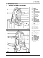
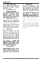
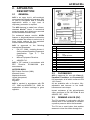
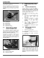
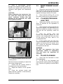
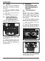
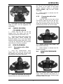
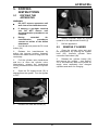
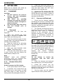
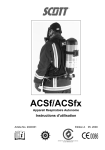
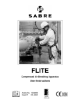
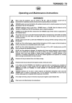
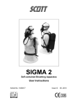
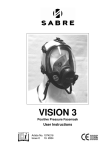
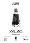
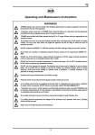
ACSf/ACSfx
Self-contained Breathing Apparatus
User Instructions
Article No. 2018790
Issue B
AS/NZS1716 : 2003 - Respiratory Protective Devices
Lic. 5021 BSI Benchmark
04. 2009
Self-contained Breathing Apparatus
Contents
WARNINGS .................................................................................................................................................. ii
1.
INTRODUCTION .............................................................................................................................. 1
1.1
GENERAL ASSEMBLY DIAGRAMS ......................................................................................... 1
1.2
BREATHABLE AIR ................................................................................................................... 2
1.3
COMPRESSED-AIR AIRLINE SUPPLIES ................................................................................ 2
1.4
PERSONNEL TRAINING .......................................................................................................... 2
1.5
SERVICING .............................................................................................................................. 2
1.6
SPARE PARTS AND ACCESSORIES ...................................................................................... 2
1.7
WARRANTY ............................................................................................................................. 2
2.
APPARATUS DESCRIPTION .......................................................................................................... 3
2.1
GENERAL ................................................................................................................................ 3
2.2
FACEMASKS ........................................................................................................................... 3
2.3
DEMAND VALVE (DV) .............................................................................................................. 3
2.4
REDUCER/CYLINDER VALVE CONNECTOR ......................................................................... 4
3.
PREPARATION FOR USE ............................................................................................................... 4
3.1
CHECK APPARATUS ............................................................................................................... 4
3.2
REPLACING SINGLE CYLINDERS .......................................................................................... 4
3.3
RESET DEMAND VALVE (DV) ................................................................................................. 5
3.4
CYLINDER PRESSURE/ LEAK TEST ...................................................................................... 5
3.5
DV AND FACEMASK ................................................................................................................ 5
3.6
HOSES ..................................................................................................................................... 6
3.7
ADJUST HEIGHT OF WAIST-BELT MODULE (FX VERSIONS ONLY) .................................... 6
4.
DONNING PROCEDURE, PRE-USE AND MONTHLY CHECKS .................................................... 6
4.1
DON APPARATUS ................................................................................................................... 6
4.2
CHECK DV/OPEN CYLINDER VALVE ..................................................................................... 7
4.3
DON FACEMASK ..................................................................................................................... 7
4.3.1
Facemasks with a Web Harness ...................................................................................... 7
4.3.2
Facemasks with a Net Harness ........................................................................................ 7
4.4
POSITIVE-PRESSURE TEST .................................................................................................. 7
4.5
FACEMASK SEAL TEST .......................................................................................................... 8
4.6
WHISTLE TEST........................................................................................................................ 8
4.7
FINAL CHECKS ........................................................................................................................ 8
4.8
AIRLINE ATTACHMENTS ........................................................................................................ 8
5.
DOFFING INSTRUCTIONS .............................................................................................................. 9
5.1
DOFFING THE APPARATUS ................................................................................................... 9
5.2
REMOVE CYLINDER ............................................................................................................... 9
6.
AFTER USE ................................................................................................................................... 10
6.1
CLEANING ............................................................................................................................. 10
6.1.1
Facemask ....................................................................................................................... 10
6.1.2
Demand Valve (DV) ........................................................................................................ 10
6.1.3
Harness and Back-pad ................................................................................................... 10
6.2
STORAGE - READY FOR USE ............................................................................................... 11
6.3
RECORD TEST DETAILS....................................................................................................... 11
7.
SCHEDULED MAINTENANCE ...................................................................................................... 11
7.1
MONTHLY .............................................................................................................................. 11
7.2
ANNUALLY............................................................................................................................. 11
DECLARATION OF CONFORMITY - MARINE EQUIPMENT DIRECTIVE ................................................ 12
Registered Office: Scott Health and Safety Limited, Pimbo Road, West Pimbo,
Skelmersdale, Lancashire, WN8 9RA, England.
i
WARNINGS
Please Read Carefully and Fully Understand
This manual is intended for use by personnel who have been trained in the use and care of
compressed-air breathing apparatus, and MUST NOT be used as a self-teaching guide by
untrained users. Failure to understand or adhere to the ACS user instructions may result in
injury or death.
Scott Health and Safety Limited has taken great care to ensure that the information in
this manual is accurate, complete and clear. However, Training and Technical Support
Services will be pleased to clarify any points in the manual and answer questions on
SCOTT breathing apparatus.
The following warnings are in accordance with certifying authority requirements and
apply to the use of breathing apparatus in general:
Breathing apparatus users must be fully trained in the use and care of selfcontained, compressed-air breathing apparatus.
Ensure that the selection of the apparatus type is sufficient for the tasks
being undertaken and the hazards likely to be encountered. Please refer to
National Regulations for guidance.
Adequate protection may not be provided in certain highly toxic atmospheres.
The apparatus must be tested and serviced in accordance with Section 7 Scheduled Maintenance and the notes in Section 1 under Personnel Training
and Servicing.
The quality of air used to supply and charge breathing apparatus must meet
the requirements of EN 12021 : 1999. See Section 1 for details.
Ensure that a good seal can be obtained between the face and facemask. The
wearing of beards, side-burns or spectacles may adversely affect the sealing
of a facemask to the wearer's face.
The apparatus is not designed for use underwater.
The harness must not be used as a vehicle seat restraint.
DISCLAIMER
Failure to comply with these instructions or misuse of the apparatus may result in:
death, injury or material damage, and invalidate any warranty or insurance claims.
COPYRIGHT
This manual must not be copied in part or whole, or used for purposes other than its intended
purpose without the written permission of Scott Health and Safety Limited.
ii
ACSf/ACSfx
1. INTRODUCTION
1.1
GENERAL ASSEMBLY DIAGRAMS
Key:
(1)
(2)
(3)
(4)
(5)
(6)
(7)
(8)
(9)
(10)
(11)
(12)
(13)
(14)
(15)
(16)
(17)
(18)
(19)
(20)
(21)
(22)
(23)
1
Back-pad
Upper Shoulder
Strap
High-pressure Hose
Front Hose Retaining
Flap
Shoulder Strap
Adjustment Buckle
Lower Shoulder
Strap
Waist-belt
Waist-belt Buckle
Height Adjustment
Mechanism (ACSfx)
Waist-belt Adjusting
Strap
Medium-pressure
Hose
Demand Valve
Warning Whistle
Pressure Gauge
Rear Hose Retaining
Flap
Cylinder Cradle
Hose Retaining Clip
Cylinder Band
Waist-belt
Adjustment Buckle
Pressure Reducer
Cylinder Connector
Cylinder Buckle
Reducer Mounting
Bracket
ACSf/ACSfx
1.2
BREATHABLE AIR
1.7
Air used to supply or charge breathing air
may be natural or synthetic and must
comply with EN 12021 : 1999 or
AS/NZS1715 : 1994.
1.3
COMPRESSED-AIR
AIRLINE SUPPLIES
These products are warranted to be free
from
defects
in
materials
and
workmanship at the time of delivery.
Scott Health and Safety Limited will be
under no liability for any defect arising
from wilful damage, negligence, abnormal
working conditions, failure to follow the
original
manufacturer’s
instructions,
misuse or unauthorised alteration or
repair.
Air for use with compressed-air airlines
must conform to EN 12021 : 1999 or
AS/NZS1715 : 1994 and must have a
dew-point sufficiently low to prevent
internal freezing when the apparatus is
used in temperatures below 4°C.
1.4
PERSONNEL TRAINING
Personnel who use self-contained,
compressed-air breathing apparatus must
be fully trained in accordance with these
instructions and national regulations.
Evidence of purchase date will need to be
provided for any claims arising during the
warranty period. All warranty claims must
be directed through Customer Services
and in accordance with our sales return
procedure.
These instructions cannot replace an
accredited training course run by fully
qualified instructors in the proper and
safe use of SCOTT breathing apparatus.
1.5
SERVICING
ACS must be serviced at scheduled
intervals by personnel who have
completed a formal training course and
hold a current certificate for the servicing
and
repair
of
SCOTT
breathing
apparatus. Details of the servicing
schedule are contained in the SCOTT
ACS Service Manual, copies of which can
only be obtained by registered holders of
a current certificate.
Your distributor or Training and
Technical Support Services at Scott
Health and Safety Limited will be
pleased to provide training course details
and quotes for service contracts.
1.6
WARRANTY
The products manufactured at our
factories in Skelmersdale and Vaasa
carry a warranty of 12 months (unless
stated otherwise) for parts, labour and
return to site. The warranty period runs
from the date of purchase by the end
user.
SPARE PARTS AND
ACCESSORIES
Customer Services provide an efficient,
friendly, customer contact point for
ordering new apparatus, spare parts and
accessories. The team can also provide
general information on SCOTT products.
2
ACSf/ACSfx
2. APPARATUS
DESCRIPTION
2.1
GENERAL
ACS is an open circuit, self-contained,
compressed-air Breathing Apparatus (BA)
for use by fire-fighters and in industrial
applications where a high level of
respiratory protection is required.
The ACS harness is made from a flameretardant KevlarTM blend. A mechanical
pressure gauge and whistle are mounted
on the left-hand shoulder strap.
For enhanced wearer comfort, ACSfx
features a height-adjustment mechanism
which enables the wearer to select one of
three height settings for the waist-belt
module relative to the back-pad.
ACS is approved to the following
International Standards:
•
EN 137 : 2006 - Including Annex A,
Self-contained Breathing Apparatus
classification: Type 2 - Fire
Fighting;
•
Marine Equipment Directive;
•
AS/NZS1716.
Key
A=
B=
C=
D=
E=
F=
G=
H=
I=
J=
K=
ACS is 'CE' marked in accordance with
EEC
Directive
EC/686/1986
plus
amendments.
NOTIFIED BODY:
BSI Product Services (0086)
Kitemark House,
Maylands Avenue,
Hemel Hempstead,
HP2 4SQ,
England.
2.2
Meaning
Symbol - refer to User Instructions
Product brand name
Product model/designation
f=
Fire
x=
Height adjustable
Apparatus description
Standards to which apparatus is certified
Number of Approval Body
Serial number of apparatus
Date of manufacture
Date apparatus commissioned
Care instructions for apparatus
Contact details of manufacturer
FACEMASKS
ACS is approved for use with Vision 3,
PanaSeal, PanaVisor and Promask PP
full facemasks, all of which conform to EN
136, Class 3.
ACS is marked in accordance with EN
137 : 2006 and AS/NZS1716 : 2003. An
explanation of those markings is given
opposite:
All are available with a five-point, fullyadjustable web harness or net headharness and neck-straps.
Impact resistance of the polycarbonate
visors conforms to EN 166 Grade B and
AS/NZS 1337 : 1992.
2.3
DEMAND VALVE (DV)
The DV operates in conjunction with the
exhale valve in the facemask to maintain
a positive pressure within the facemask.
The DV has a reset button that enables
wearers to close the airflow through the
3
ACSf/ACSfx
DV, allowing the facemask to be removed
without loss of cylinder air.
3. PREPARATION FOR
USE
When the apparatus is donned the DV is
normally ‘reset’ (closed), and is opened
(activated) when the wearer takes a first
breath.
3.1
When ACS is to be used with an airline
check that:
i)
The airline is in good condition and
free from splits, bulges and
abrasions.
ii)
The airline connector is in good
condition and that it connects
securely to the ACS airline
manifold.
iii)
The air-supply conforms to EN
12021 : 1999 or AS/NZS1715 :
1994 (see Section 1.2).
iv)
The ACS airline coupling is in good
condition.
Main components:
(24)
(25)
(26)
(27)
2.4
CHECK APPARATUS
Visually inspect to ensure that ACS is
clean and in good condition. Check that
all hose retaining flaps (4) and (15) are
closed. Fully slacken the waist-belt and
shoulder straps ready for use.
Reset Button
Bypass Knob
Locking Catch
Outlet Port O-Ring
3.2
REDUCER/CYLINDER
VALVE CONNECTOR
1.
The combined pressure reducer and
cylinder valve connector reduces high airpressure from the cylinder to a medium
pressure of between 5 and 9 bar.
REPLACING SINGLE
CYLINDERS
Close the cylinder valve.
2.
Open the DV bypass knob (25) to
vent the system.
3.
Unscrew the cylinder connector
hand-wheel (28).
Connection to a cylinder is made by the
threaded hand-wheel on the cylinder
valve connector which locates within the
cylinder valve. Please refer to Section 3.2
for further details.
4.
Simultaneously depress the two
cylinder buckle buttons and pull the
cylinder buckle (22) to release from the
cylinder. Loosen cylinder band (18) and
remove the cylinder by sliding it in either
direction.
Main components:
(28) Connector Hand-wheel
(29) Connector O-Ring
4
ACSf/ACSfx
5.
Slide a fully-charged cylinder
through the loosened cylinder band (18).
Position the cylinder valve outlet onto the
connector and tighten the hand-wheel
(28).
3.3
RESET DEMAND VALVE
(DV)
1.
Press the reset button (24) on the
side of the DV and check that the bypass
knob (25) is turned so that the flat on the
bypass knob aligns with the DV outlet.
CAUTION:
Before tightening the hand-wheel into
the valve port, check that the handwheel connector O-Ring (29) and
threads on the connector are clean
and in good condition.
2.
Check that the O-Ring (27) on the
DV outlet is clean and in good condition.
3.4
CYLINDER PRESSURE/
LEAK TEST
1.
Slowly open cylinder valve fully and
allow 10 seconds for the apparatus to
pressurise.
2.
Check that the pressure gauge (14)
shows the cylinder is at least 80% FULL
(240 bar for 300 bar cylinders, 170 bar for
200 and 207 bar cylinders). Listen for
leaks.
3.
Close the cylinder valve and
monitor the pressure gauge for one
minute. If the reading falls by more than
10 bar during this time, there is an
unacceptable leak.
6.
Take up the slack on the cylinder
band (18).
4.
If the system fails the leak test:
close the cylinder valve, vent air from the
system by opening the DV bypass knob
(25). Check all pneumatic connections
and repeat the leak test.
WARNING:
DO NOT use apparatus that leaks
excessively. Attach an explanatory
note and return the apparatus for
servicing.
3.5
DV AND FACEMASK
1.
Check that the facemask is clean
and undamaged.
7.
Push the cylinder buckle (22) to the
closed position.
2.
Fit the DV to the facemask and
check that the locking catch (26) engages
fully. Twist the DV gently to confirm that it
has.
Should it become necessary to adjust the
size of the cylinder band:
i)
Ensure that the cylinder buckle is
unlocked and in the open position.
ii)
Adjust the tension of the cylinder
band.
iii)
Close the cylinder buckle and
check that the cylinder is held securely.
Repeat as necessary.
5
ACSf/ACSfx
3.6
HOSES
4. DONNING
PROCEDURE, PREUSE AND MONTHLY
CHECKS
1.
Check all hoses for damage and
excess wear. Flex hoses to reveal any
splits, cracks or crazing (minor crazing is
acceptable).
2.
Check any couplings for damage
and excess wear; and ensure that they
can be opened.
4.1
3.
When closed, check that they form
a secure coupling.
4.
3.7
DON APPARATUS
Note:
Specialist Users (such as Emergency
Services)
may
operate
alternative
donning procedures that conform to the
relevant statutory regulations and have
been approved by Scott Health and
Safety Limited.
Replace damaged or worn hoses.
ADJUST HEIGHT OF
WAIST-BELT MODULE
(FX VERSIONS ONLY)
1.
Check that the ACS and facemask
harnesses are fully slackened and that
the DV is connected to the facemask.
If required, adjust the height of the waistbelt module relative to the back-pad:
2.
Hang the facemask around the
neck by its neck-strap.
3.
Pass the right arm through the
shoulder strap (2), swing the back-pad (1)
across the back and slip the left arm
through the opposite shoulder strap (2).
i)
Using the fingers and thumb,
squeeze together the two halves of the
release catch (A).
ii)
Slide the waist-belt module to the
desired position (B), taking care to ensure
that the adjustment mechanism is
securely located in one of the three preset height settings.
4.
Fasten the waist-belt buckle (8).
5.
Pull the ends of the waist-belt
adjusting straps (10) forward until secure
and comfortable on the hips.
6
ACSf/ACSfx
the face and the head-harness pad is in
the centre of the back of the head.
Tighten harness straps in sequence:
Bottom, Middle, Top. DO NOT OVERTIGHTEN.
3.
Inhale deeply to activate the DV.
Breathe normally.
4.3.2
1.
Hold the mask by the side of the
net harness, place the chin into the chincup and pull the mask onto the face.
Grasp the pull-strap at the rear of the net
harness and pull the net over the head.
6.
Pull down on the lower shoulder
strap (6) ends until the apparatus fits
comfortably.
4.2
Facemasks with a Net
Harness
CHECK DV/OPEN
CYLINDER VALVE
1.
Check that the flat on the DV
bypass knob (25) aligns with the DV
outlet and press the reset button (24).
2.
Open the cylinder valve slowly with
your right hand, whilst holding the
pressure gauge (14) in your left. Check
that the pressure gauge reads 80% FULL
(170 bar for 200 and 207 bar cylinders
and 240 bar for 300 bar cylinders).
4.3
4.3.1
2.
Tighten harness side straps. DO
NOT OVER-TIGHTEN.
DON FACEMASK
Facemasks with a Web
Harness
3.
Inhale deeply to activate the DV.
Breathe normally.
1.
Hold the head-harness lower
straps, place chin into the chin-cup and
pull straps over the back of the head,
brushing hair away from face-seal.
4.4
POSITIVE-PRESSURE
TEST
With the cylinder valve open, insert a
finger under face-seal and check for a
steady outward flow of air. Remove finger
and allow mask to re-seal.
2.
Adjust the facemask top strap so
that the mask is at the correct level with
7
ACSf/ACSfx
4.5
FACEMASK SEAL TEST
4.8
1.
Close the cylinder valve and
continue to hold the hand-wheel. Hold
breath for 10 seconds and listen carefully
for leaks. A leak will cause the pressure
gauge reading to fall.
2.
Make connection to an appropriate
connector
capable
of
supplying
breathable compressed air (see Section
1.3).
2.
If the facemask fails the leak test:
open the cylinder valve, loosen the headharness adjust the facemask and repeat
the test.
4.6
WARNING:
•
Airlines should be at least 15
metres long.
•
Use
anti-static
hoses
in
flammable
or
explosive
atmospheres.
•
Close cylinder valve while
breathing from the airline.
WHISTLE TEST
1.
With the cylinder valve still closed,
slowly breathe down the air from the
system. Check that the whistle (13)
sounds clearly as the pressure gauge
falls to 55 bar (±5 bar).
2.
Once the whistle has sounded,
open the cylinder valve fully.
3.
Check that the connection is secure
and that the connector releases easily,
without sticking.
WARNING:
DO NOT use apparatus that fails this
test. Attach an explanatory note and
return for servicing.
4.7
AIRLINE ATTACHMENTS
1.
Check the supply airline flow and
pressure. Remove connector dust caps
and check for wear and damage.
4.
Press the DV reset button (24).
5.
Pressurise the attachment and
check all connections for leaks. Ensure
that the female connector on the airline
attachment does not leak.
FINAL CHECKS
1.
Check that the cylinder valve is fully
open and that the pressure gauge (14)
shows that there is sufficient air.
WARNING:
DO NOT use attachments that show
signs of excessive wear or damage, or
that leak excessively.
2.
Turn on the DV bypass knob (25)
and check for a steady flow of air into the
mask. Close the DV bypass knob.
6.
8
Replace dust caps.
ACSf/ACSfx
5. DOFFING
INSTRUCTIONS
5.1
DOFFING THE
APPARATUS
WARNING:
•
DO NOT remove apparatus until
well clear of the hazardous area.
•
If wearing a gas-tight chemical
suit, DO NOT remove until
decontamination procedures are
complete.
•
During
extended
decontamination
procedures,
connect an airline to the Airline
attachment.
6.
Slacken shoulder straps by pulling
upwards on the adjustment buckles (5).
7.
1.
Hold breath and press the DV reset
button (24).
5.2
REMOVE CYLINDER
1.
Close the cylinder valve and vent
the pneumatics by opening the bypass
knob (25). Unscrew cylinder valve
connector hand-wheel (28).
2.
Release the head-harness by
pulling the harness buckles forwards.
Remove the mask and let it hang from the
neck strap.
2.
Release the cylinder buckle (22)
and remove the cylinder - (see Section
3.2 of this Manual). Mark the cylinder as
empty, store separately from charged
cylinders and return for charging.
3.
Pull the cylinder valve hand-wheel
and turn to close the cylinder valve.
Alternatively, release the hand-wheel
locking mechanism and close the cylinder
valve.
4.
Open the DV bypass knob (25) to
depressurise the system. Turn the bypass
to OFF.
5.
Doff the apparatus.
Release the waist-belt buckle (8).
9
ACSf/ACSfx
3.
Clean the valve body using a lintfree cloth moistened in a mild solution of
soap and warm water. DO NOT store
apparatus until completely dry.
6. AFTER USE
ACS must be cleaned and tested as
detailed in the following instructions.
6.1
4.
Operate the DV locking catch (26)
and bypass knob (25) several times and
ensure that they move freely. If either is
not free-moving, attach explanatory note
and return for servicing.
CLEANING
CAUTION:
•
DO NOT immerse the pressure
reducer (20) and pneumatics
assembly in liquids.
•
USE
ONLY
the
specified
methods and materials. DO NOT
use bleach, solvent, detergent or
abrasive cleaners.
•
Dry thoroughly away from direct
heat and sunlight prior to
storage.
6.1.1
6.1.3
2.
The harness and back-pad can be
sponged clean with a mild solution of
soap and warm water or, following
removal of the pneumatics can be
manually cleaned in a bath containing
cleaning or disinfecting solutions or
machine-washed to the following care
instructions:
Facemask
1.
Disconnect
facemask.
the
DV
from
Harness and Back-pad
1.
Check that the harness webbing
and fittings are not worn or damaged; and
that buckles and fastenings are fully
operational. Apparatus with major defects
must be returned for servicing, with an
explanatory label attached.
the
2.
Wash and disinfect the mask
thoroughly in a solution of TriGeneTM and
warm water (see following note).
3.
Rinse the mask thoroughly in clean
running water. Pay particular attention to
flushing out the exhale valve.
4.
Hang the mask by its neck-strap
and allow to dry thoroughly, away from
direct heat or sunlight.
3.
To remove the pneumatics, release
the hoses from all hose retaining flaps (4)
and (15) and remove from hose retaining
clips (17) on the cylinder cradle (16).
5.
When dry, wipe facemask seals
with TriGeneTM disinfectant wipes.
6.
Polish the visor inside and out with
a clean, lint-free cloth and slacken the
head-harness, ready for use.
4.
Turn the reducer (20) through 90
degrees
and
remove
complete
pneumatics from the reducer mounting
bracket (23).
Note:
liquid
and
TriGeneTM
TriGeneTM
disinfecting wipes are available from
Scott Health and Safety Limited.
CAUTION:
Do not attempt
pneumatics with
retained.
6.1.2
5.
When the harness and back-pad
are completely dry, re-fit the pneumatics.
Demand Valve (DV)
CAUTION:
DO NOT immerse the DV in liquids.
1.
to remove
the hose
the
still
6.
Locate the reducer into the
mounting bracket and turn through 90
degrees so that the hoses face towards
the top of the back-pad.
Fit the yellow cap on the DV outlet.
2.
If required, use a small brush (eg
toothbrush) and a mild solution of soap
and warm water to clean around the
locking catch (26) and bypass knob (25).
7.
Clip the hoses into the retaining
clips at the side of the cylinder cradle.
10
ACSf/ACSfx
8.
Secure the hoses with the hose
retaining flaps ensuring that the highpressure gauge, whistle and hose is on
the left-hand shoulder strap and the
medium-pressure hose and DV is on the
right-hand shoulder strap.
6.2
7. SCHEDULED
MAINTENANCE
7.1
MONTHLY
Test ACS in accordance with the
instructions given in Section 3 and
Section 4 of this Manual. Record test
details in the apparatus’ BA Logbook.
This record is mandatory in the UK and
most EC countries; and must be kept up
to date and available for inspection.
Please see Section 6.3 for details.
STORAGE - READY FOR
USE
1.
Fully extend the shoulder straps,
waist-belt and facemask head-harness.
2.
The apparatus must be stored in a
clean, dry environment away from direct
heat and sunlight. Storage temperature
should not exceed -10°C to +40°C.
7.2
ANNUALLY
RECORD TEST DETAILS
ACS must be returned for a workshop
service annually and for a major
workshop service at six-yearly intervals.
Record test details in accordance with
local regulations in a Breathing Apparatus
Logbook (available from Scott Health
and Safety Limited).
After each workshop service, perform the
user checks detailed in Section 3 and
Section 4 of this Manual prior to returning
ACS to service.
6.3
Information recorded usually includes:
•
Name and address of employer
responsible for the apparatus.
•
Make, model number or mark
description of any distinguishing
features, sufficient to enable clear
identification.
•
The date of the examination
together with the name, signature
or unique authentication mark of
the examiner.
•
The condition of the apparatus and
details of any defects found and
any remedial action taken, including
any airline supply equipment used
with the apparatus.
•
Cylinder air pressure.
Check that workshop service details have
been recorded in the apparatus’ BA Log.
11
ACSf/ACSfx
DECLARATION OF CONFORMITY
MARINE EQUIPMENT DIRECTIVE
Scott Health and Safety Limited
Pimbo Road, West Pimbo,
Skelmersdale, Lancashire,
WN8 9RA, England.
declares that the following Personal Protective Equipment:
‘Sigma ACSm, ACSi, ACSf and ACSfx Self-contained Compressed Air Breathing
Apparatus’
•
Is in conformity with the provisions of Council Directive 96/98 EC on Marine
Equipment. Type-Examination Certificate BSI/A.1/3.7/541173 issued by BSI Product
Services (Notified Body No 0086) relates.
•
Is in conformity with the provisions of Council Directive 89/686/EEC relating to
Personal Protective Equipment when assessed against Harmonised Standard BS
EN137. Type-Examination Certificate No CE536078 issued by BSI Product Services
(Notified Body No 0086) relates.
•
Is manufactured under a Quality Control System which has been satisfactorily
assessed against the requirements of Article 11, Section B of Council Directive
89/686/EEC; 96/98 EC MED MODULE D and Production Quality Assurance Module
D Certificate BSI/MED/PC/90907 issued by BSI Product Services (Notified Body No
0086) relates.
Robert Carr
Technical Director,
Scott Health and Safety Limited.
th
24 June 2008
12
Scott Health and Safety Limited
Pimbo Road, West Pimbo,
Skelmersdale, Lancashire,
WN8 9RA, England.
Tel: +44 (0) 1695 711711
Fax: +44 (0) 1695 711775