1
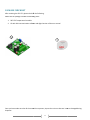
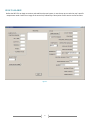
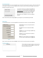
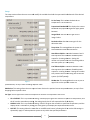
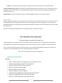
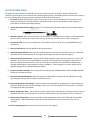
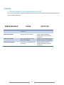
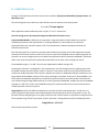
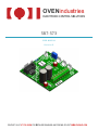
OVENindustries
industries
ELECTRONIC CONTROL SOLUTIONS
5R7-573
USER MANUAL
Revision D
CONTACT US AT 877-766-OVEN FOR DETAILED DRAWINGS AND PRICING OR VISIT WWW.OVENIND.COM
Table of Contents
TABLE OF FIGURES .................................................................................................................................................................. 1
MANUAL OVERVIEW ............................................................................................................................................................... 2
BRIEF OVERVIEW ................................................................................................................................................................. 2
WHO SHOULD READ THIS MANUAL.................................................................................................................................... 2
TECHNICAL SUPPORT .......................................................................................................................................................... 2
SUPPLEMENTAL INFORMATION ......................................................................................................................................... 2
PACKAGE CHECKLIST ............................................................................................................................................................... 3
GENERAL DESCRIPTION ........................................................................................................................................................... 4
FEATURES & SPECIFICATIONS ............................................................................................................................................. 4
GUI AT A GLANCE .................................................................................................................................................................... 5
PC Communications ........................................................................................................................................................ 6
Sample Data .................................................................................................................................................................... 6
The Message Box ............................................................................................................................................................ 6
Setup ............................................................................................................................................................................... 7
Sensor Types ................................................................................................................................................................... 8
PREFLIGHT CHECKLIST ......................................................................................................................................................... 8
SET UP INSTRUCTIONS .......................................................................................................................................................... 10
APPENDIX .............................................................................................................................................................................. 12
A.
TROUBLE SHOOTING THE COMMUNICATIONS PORT ............................................................................................... 12
B.
5 MINUTES TO P.I.D. ................................................................................................................................................. 13
C. SENSOR TYPES AND RECOMMENDED TEMPERATURE RANGES ................................................................................ 15
TABLE OF FIGURES
Figure 1 ................................................................................................................................................................................... 5
Figure 2 ................................................................................................................................................................................... 6
Figure 3 ................................................................................................................................................................................... 6
Figure 4 ................................................................................................................................................................................... 6
Figure 5 ................................................................................................................................................................................... 7
1
MANUAL OVERVIEW
BRIEF OVERVIEW
The 5R7-573 user manual describes the processes involved in the installation, and configuration of the product,
as well as the standard methods of operation. It is advised that users familiarize themselves with the
information detailed in this manual before operating the unit in order to ensure user safety.
WHO SHOULD READ THIS MANUAL
This manual contains important information anyone involved in the installation, maintenance, or operation of
the 5R7-573.
TECHNICAL SUPPORT
Our technical support team comprised of knowledgeable engineers who are always willing to answer any
questions you may have about our products. We can be reached both by telephone (during standard business
hours) and through our website. If you have any other questions in regard to possible custom applications or
specific needs for a product, we are more than willing to help you find the perfect temperature control solution.
By Telephone: 877-766-6836 (Monday-Friday, 8:00 am-5:00 pm EST.)
On the Web: www.ovenind.com
SUPPLEMENTAL INFORMATION
Data sheets and customer drawings are always available for reference to our customers. We can also provide
software updates, .DLL files, and other important information. If there is any other information you require, our
technical support team is always ready to assist you with whatever you might need. Additionally, information
can be downloaded from our website.
2
PACKAGE CHECKLIST
After receiving the 5R7-573, please
se check for the following:
Make sure the package includes the following items:
1. 5R7-573 Temperature Controller
2. CD with GUI communication
on software and digital version of the user manual
1
2
Once you have made sure that all the materials are present, inspect the unit to make sure it was no damaged during
shipment.
3
GENERAL DESCRIPTION
The 5R7-573 is a bi-directional thermoelectric controller with a full solid state MOSFET H-Bridge that can be applied to a
broad spectrum of applications that require precision temperature control. The flexible design allows users to configure
the unit to just heat, just cool, or seamlessly transition between the two instantaneously.
The 5R7-573 can be tuned in either Celsius or Fahrenheit, and the temperature resolution for either setting is 0.1°. This
allows the unit to provide control stability up to ±0.1° in a well designed thermal system.
FEATURES & SPECIFICATIONS
•
•
•
•
•
•
•
•
•
•
•
•
•
•
•
•
•
RoHS Compliant
Small Footprint
Thermistor sensor input
900 Hz Base Frequency Pulse Modulated Output
Heat, Cool or H-Bridge operating modes
o Red LED Heating Mode
o Green LED Cooling Mode
PID control, parameters set via GUI
Optional High and Low Alarm Settings via GUI
Optional Remote LED Display
Optional Remote Set Potentiometers
Proportional Integral Control Algorithm
TTL to USB communication via Optional Cable
•
•
•
•
4
Input Voltage: 6 to 28 VDC
Output Voltage: 0 to 28 VDC
Load Current: 0.1 to 12.5 A
Temperature Resolution: 0.01°C
Control Stability: ± 0.1°C
PID Functions:
o Bandwidth : 0.1 to 55°C
o Integral: 0 to 10 repeats per minute
o Derivative: 0 to 10 minutes
Ambient Temperature range: -40 to 250°C
450 W Output Power Control
Bidirectional load rating: 12.5 AMP max
Dual power supply to separate load and logic
GUI AT A GLANCE
Before the 5R7-573 can begin to monitor and stabilize a thermal system, it must be set up to match the user’s specific
temperature needs. Below is an image of the entire GUI, followed by a description of each section and its functions.
Figure 1
5
PC Communications
The PC communication is the most important thing to note when first opening the PC program. After the unit has been
connected to a computer,
ter, this section allows the user to select the comm port that will be used for communication
between the computer and the unit.
To set up the comm port, first determine which port the
connection is on in the windows device manager. Select
Ports (COM & LPT) from the menu to locate your specific
port number. Select this number from the drop down
menu and hit the Start/Stop Comm button. If the
Message box reads “COMM OK”, then you are ready to
proceed.
Figure 2
Note: In the event any other message appears, refer to appendix 1 for troubleshooting assistance.
Sample Data
The sample data section is a short listing of the basic information the controller is currently monitoring.
monitoring
Control Sensor: The current temperature of the
control sensor.
Set Temp: The current set temperature of the
system.
Output %: The current percentage of power being
applied to the system.
Sensor 2: The current temperature of the alarm
sensor (if applicable).
R8 Set: This number displays the set temperature
from the remote set potentiometer (if applicable).
Figure 3
Note: In order to have these numbers display
displayed,
ed, the unit must be currently connected to the controller.
The Message Box
This box displays messages to the user in the event
ev
of an
error in the system. Note: See Appendix A (page 13) for
help with troubleshooting errors.
Figure 4
6
Setup
The setup section allows the user to set and modify the variables that hold the system within the bounds of the desired
temperature.
PC Set Temp: This is where the desired set
temperature is set for the unit.
Proportional Bandwidth: This displays the current
bandwidth the proportional gain will apply power
between.
Integral Gain: Sets the current gain for the
integral value.
Derivative Gain: Sets the current gain for the
derivative value.
Temp Units: This setting allows the system to
switch between Celsius and Fahrenheit.
Heat Side multiplier: A number between 0 and 1
that represents the maximum allowable power
output for a heating element. Setting this
number to 0 prevents the unit from being able to
heat the system. (0.5=50% power).
Cool Side multiplier: A number between 0 and 1
that represents the maximum allowable power
output for a cooling element. Setting this number
to 0 prevents the unit from being able to cool the
system. (0.5=50% power).
R8 Max Set: This setting allows the user to put an
upper limit on the optional remote set
Figure 5
potentiometer, to stop it from exceeding a specific value.
R8 Min Set: This setting
etting allows the user to put an lower limit on the optional remote set potentiometer, to stop it from
dropping below a specific value.
Set Type: The set type menu contains four options for how the set temperature can be set:
•
•
•
PC or DISPLAY: This is a precedence
dence setting, if the display has given the controller a specific set temperature, and
the PC sends a contradictory setting, the value given by the PC will supersede that of the display.
DISPLAY or PC: This is a precedence setting, if the PC has given the controller a specific set temperature, and the
display sends a contradictory setting, the value given by the display will supersede that of the PC.
DIFF SET: This setting allows the controller to use differential control, allowing the PC to use the PID settings to
dynamically apply or reduce power to system to stay within the specified parameters.
7
•
R8 SET: This setting allows the controller’s set temperature to be specified by a remote potentiometer.
Control & Temp 2 Sensor Types: These values coincide with Oven Industries temperature sensors, allowing the user to
integrate a pair of the same sensor, or two different sensors with no need to worry about setting up the thermistor
curves for each sensor.
Output Enable: This check box allows the user to manually toggle the power to the output on and off.
Sensor Types
This pair of selections allows the user to adjust the unit to match any pair of desired sensor curves. Since each sensor is
handled separately, two uniquely valued sensors can be used together for seamless integration. The values will be
adjusted automatically using a polynomial calculated lookup table that matches any Oven Industries sensor by using the
drop down menu.
Note: A list of the general specifications for each family of sensor is located on page 22.
The Thermistor Curve Equation:
T=1.0/(A+(B*log(R))+(C*log(R)^2)+(D*log(R)^3))-E
Using this equation, it is possible to fine tune the system around a specific sensor. This calibration is automatically
calculated by the unit based on the coefficients and the series of the sensor that is specified in the Sensor Types box.
Note: In the event that the sensors in the sensor type list do not match the specifications required for a project, any
thermistor curve can be added to the list by simply contacting Oven Industries.
Note: For more information on PID, refer to appendix B.
PREFLIGHT CHECKLIST
Did you…
•
•
•
•
•
•
•
•
•
Select a TEM to match the voltage and current rating of the unit?
Connect the temperature probe to the controller?
Connect TEM connections to the controller?
Connect the serial interface cable?
Connect power to the controller?
Select a serial port on your computer?
Initialize the GUI (graphic user interface) with the controller?
Select the appropriate sensor from the GUI listbox?
Check for a valid temperature via sample function?
8
•
•
•
Choose a temperature setpoint? (start with default tuning parameters)
Enable output to be on?
Send new settings to the controller?
9
SET UP INSTRUCTIONS
This guide has been provided to get the 5R7-573 set up and running as fast as possible. Please read the entire
instruction set and ensure you are familiar with it before beginning setup. Not following these instructions may result in
the unit not being able to properly maintain the temperature of the thermal system.
1. DC Power: Without a load (heater or TEC) connected to the unit, connect the 5R7-573 to a DC power source
using terminal block JP3 (see CDR-00426 for wiring information). Once the controller has been powered, a
green LED on the board should begin blinking.
2.
Attach the Communications Cable: Connect a TTL to RS232 communications cable from the controller (JP4) to
your PC.
3. Attach the Sensors: Place the control sensor into the heater or TE module thermal system at the desired control
point. Connect the sensor to the back of the unit. Do the same for the alarm sensor if you are using one.
4. Connect the Load: Connect your load (heater or TE module) to terminal block JP3 (see CDR-00426 for wiring
information).
5. Check all connections (see CDR-00426 for wiring information).
6. Launch the Setup Software: Now insert the software disk that came with the controller into the PC. Select the
executable file on the disk and the set up program should begin (see GUI at a Glance on page 7).
7. Select the Communications Port: Using the SELECT PORT dropdown menu, find the virtual comm. port for the
controller (If you are not sure how to find the correct port, the windows device manager will enumerate all
ports currently connected to the PC). Once the correct port is selected hit the START/STOP COMM button, a
message should appear in the message box saying “COMM OK”, if this message is not shown, please refer to
appendix B (page 13) for troubleshooting information.
8. Set the Thermistor Constants: This is simply done by selecting the CONTROL SENSOR TYPE and TEMP2 SENSOR
TYPE for the relevant thermistor.
9. Select the Heat/Cool Multipliers: Select the appropriate HEAT/COOL multipliers for your application. If using
only heating or cooling, set the multiplier not being used to 0.
10. Select the appropriate PID settings: Using the proportional bandwidth (P), Integral gain (I), and Derivative gain
(D) boxes, set the controller values accordingly. Note: If you are unsure of how to use these values, see Section
B. on page 13 for more information.
11. Choose Temperature Units: The controller can work in both Celsius and Fahrenheit, choose a selection from the
drop down menu for your preferred unit of measure. NOTE: Ambient room temperature of 70°F is about 25°C.
12. The Set Point Temperature: Enter the desired set point temperature as the PC SET TEMP and click the SEND
VALUES button. SEND VALUES takes all the information specified in the set up menu and relays it to the
controller.
13. Exit the Setup Program: Use the File menu and Exit to exit the program.
10
14. Setup is Complete: It is a good idea to use safe temperature settings in order to become accustomed to your set
up and to tuning the controller.
11
APPENDIX
A. TROUBLE SHOOTING THE COMMUNICATIONS PORT
This section can be used as a guide to navigate the most common errors encountered while making connections
to the communications port.
ERROR MESSAGE
CAUSE
SOLUTION
Comm Port Timeout
No power to temperature
control unit
Supply power to the unit
Comm Port Timeout
Wrong comm port selected
Comm Port Timeout
Incorrect wiring of the comm
port to the computer
Check computer hardware
settings and set to the correct
comm port
Check for the correct wiring from
the comm port to the computer
Comm Port Open Error
No comm. port available at this
port setting
12
Check computer hardware
settings and set to the correct
comm port
B. 5 MINUTES TO P.I.D.
Tuning the TE temperature controller involves three variables. (P)ropotional bandwidth, (I)ntegral action, and
(D)erivative rate.
The control algorithm sums the three values of these terms to determine the output power.
P + I + D = % Power Applied
Most applications work satisfactorily with only the “P” and “I” values used.
Start the tuning process by setting the Integral and Derivative functions to zero.
Proportional Bandwidth is defined as the temperature range around the set-point where the controller
modulates (proportions) the output power. In a heating application, if the temperature is above the
proportional band, the controller output is OFF. If the temperature is below the proportional band, the
controller output is ON.
Each thermal system has its own time constants determined by the thermal mass of the components and the
placement of the sensor relative to the load. To tune the system the bandwidth must be wide enough that the
controller can sense a change and react to it before the temperature drifts outside the bandwidth. If the bandwidth is too small the output will oscillate above and below the set-point, never settling into control.
The bandwidth range is 1° to 100°. The units are shipped with a default setting of 20°.
Assuming the controller is configured for your requirements, start the tuning process by applying power with
the default settings and observing the system’s response. If the system comes into the proportional band and
maintains a steady temperature near set-point, without over shoot, the bandwidth setting is satisfactory or too
large. Reduce the bandwidth setting until the system just begins to oscillate. At this point, the bandwidth is too
small. Note the bandwidth setting that just caused the system to oscillate, record the period of oscillation for
use in determining the Integral Reset setting. To set the proportional bandwidth, multiply the current bandwidth
setting by 1.5 and use it as your new bandwidth setting. The system should come into control and maintain a
steady temperature near the set-point.
Integral Reset monitors the difference between the set point and the actual temperature. Its function is to
slowly change the output power until the delta between actual temperature and set temperature is zero. The
function works by integrating the error signal at fixed intervals. These intervals are expressed in repeats/minute.
The acceptable range is 0.01 to 10 repeats /minute. Start with a setting determined by the following formula.
Integral Reset = 1/P x 1/2
Note: Period is expressed in minutes.
13
Example:
The system‘s period of oscillation with narrow bandwidth was 75 seconds. Therefore
the suggested Integral Rate is:
Integral Reset = 1/1.25min. X 1/2
Integral Reset = 0.4 repeats/minute
For slower response reduce the number of repeats per minute.
NOTE: DERIVATIVE RATE IS DIFFICULT TO APPLY. IF YOU ARE NOT EXPERIENCED IN PROCESS CONTROL, ASK
FOR HELP NOW!
Derivative Rate senses the rate of change of the temperature and allows the controller to anticipate power
needed to compensate for rapid changes in system loading. This term is generally used only on very sluggish
systems or where very quick response is necessary. The acceptable range is 0.01 to 10 cycles/ minute.
To determine an appropriate derivative rate, use the following formula.
Derivative Rate = Integral Reset / 10
For the example above the Derivative Rate would be .06 cycles per minute.
The Derivative function is difficult to use and often causes more trouble than it is worth! Our technical support
team is always available to help guide you through this process.
14
C. SENSOR TYPES AND RECOMMENDED TEMPERATURE RANGES
This sensor chart will help guide you to selecting a sensor that best fits your application. All Oven Industries sensors
come in wide variety of optional sheaths and can be either leaded and RoHS compliant.
Oven Industries Sensors:
Sensor Family
Tolerance
Temperature Range
Base Resistance (@25°C)
TR67
±1.0°C (0°C to 100°C)
-20° to 110°C
15KΩ
TR91
±1.0°C (0°C to 100°C)
-40° to 150°C
10KΩ
TR104
±1.0°C (0°C to 100°C)
0° to 150°C
50KΩ
TR136
±0.1°C (0°C to 70°C)
-20° to 110°C
15KΩ
TR141
±1.0°C (-40° to 70°C)
-40° to 90°C
5KΩ
TR165
±1.0°C (0°C to 200°C)
25°C to 250°C
230KΩ
Other General Sensors:
Sensor Family
Temperature Range
Base Resistance (@0°C)
PT100
-200° to 850°C
100Ω
PT1000
-200° to 850°C
1KΩ
15