1
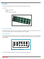
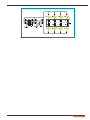
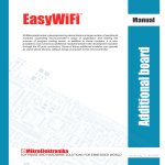
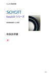
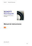
All Mikroelektronika’s development systems feature a large number of peripheral
modules expanding microcontroller’s range of application and making the
process of program testing easier. In addition to these modules, it is also
possible to use numerous additional modules linked to the development system
through the I/O port connectors. Some of these additional modules can operate
as stand-alone devices without being connected to the microcontroller.
Manual
Additional board
EasyLED
™
MikroElektronika
EasyLED
The EasyLED additional board is used to connect a development system port to LEDs.
Key features:
- Parallel communication;
- 8 LEDs;
- 3.3V or 5V power supply voltage.
Figure 1: EasyLED additional board
How to connect the board?
The EasyLED additional board can be easily connected to a development system via an IDC10 connector CN2. The
CN1 connector is used to access the port pins the additional board is connected to.
How to use the board?
The EasyLED board is used to show the logic level on the development system ports. When a pin is driven high (logic
1), the appropriate LED connected to that pin is turned on. Likewise, if a pin is driven low (logic 0), the appropriate LED
will not illuminate.
Figure 2: Dimensions of the EasyLED board
Note: When the EasyLED board features red LEDs, the value of the RN1 resistor is 4K7.
MikroElektronika
Figure 3: The EasyLED board connection schematic
MikroElektronika
MikroElektronika
If you have any questions, comments or business proposals, do not hesitate to contact us at [email protected]
If you are experiencing some problems with any of our products or just need additional information, please place your ticket at
www.mikroe.com/en/support
If you want to learn more about our products, please visit our website at www.mikroe.com