1
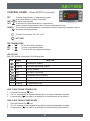
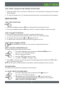
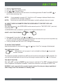
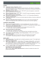
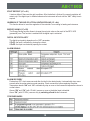
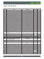
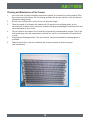
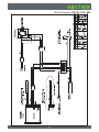
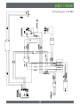
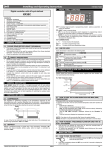
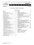
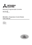
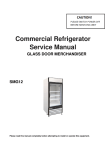
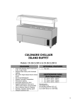
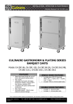
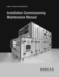
OPERATING INSTRUCTIONS
LTF 85 / 225 / 325 / 425 / 535
INDEX
PAGE
Low Temperature Freezing Box . . . . . . . . . . . . . . . . . . . . . . . . . . . . . . . . . . . . . . . . . . . . . . . . . . . . . . . 3
Operating Instructions. . . . . . . . . . . . . . . . . . . . . . . . . . . . . . . . . . . . . . . . . . . . . . . . . . . . . . . . . . . . . . . 4
Electrical Connection . . . . . . . . . . . . . . . . . . . . . . . . . . . . . . . . . . . . . . . . . . . . . . . . . . . . . . . . . . . . . . . 4
The Cooling System. . . . . . . . . . . . . . . . . . . . . . . . . . . . . . . . . . . . . . . . . . . . . . . . . . . . . . . . . . . . . . . . . 4
Installing The Freezer . . . . . . . . . . . . . . . . . . . . . . . . . . . . . . . . . . . . . . . . . . . . . . . . . . . . . . . . . . . . . . . 5
Before Commissioning . . . . . . . . . . . . . . . . . . . . . . . . . . . . . . . . . . . . . . . . . . . . . . . . . . . . . . . . . . . . . . 5
Start Procedure . . . . . . . . . . . . . . . . . . . . . . . . . . . . . . . . . . . . . . . . . . . . . . . . . . . . . . . . . . . . . . . . . . . 5
Caution!. . . . . . . . . . . . . . . . . . . . . . . . . . . . . . . . . . . . . . . . . . . . . . . . . . . . . . . . . . . . . . . . . . . . . . . . . . 5
Control Panel . . . . . . . . . . . . . . . . . . . . . . . . . . . . . . . . . . . . . . . . . . . . . . . . . . . . . . . . . . . . . . . . . . . . . 6
Main Functions. . . . . . . . . . . . . . . . . . . . . . . . . . . . . . . . . . . . . . . . . . . . . . . . . . . . . . . . . . . . . . . . . . . . 7
Parameters . . . . . . . . . . . . . . . . . . . . . . . . . . . . . . . . . . . . . . . . . . . . . . . . . . . . . . . . . . . . . . . . . . . . . . . 9
Digital Input . . . . . . . . . . . . . . . . . . . . . . . . . . . . . . . . . . . . . . . . . . . . . . . . . . . . . . . . . . . . . . . . . . . . . .10
Connections . . . . . . . . . . . . . . . . . . . . . . . . . . . . . . . . . . . . . . . . . . . . . . . . . . . . . . . . . . . . . . . . . . . . . . 13
Default Setting Values . . . . . . . . . . . . . . . . . . . . . . . . . . . . . . . . . . . . . . . . . . . . . . . . . . . . . . . . . . . . . . 14
Cleaning And Maintenance of The Freezer . . . . . . . . . . . . . . . . . . . . . . . . . . . . . . . . . . . . . . . . . . . . . . 15
Relocating or Moving The Freezer . . . . . . . . . . . . . . . . . . . . . . . . . . . . . . . . . . . . . . . . . . . . . . . . . . . . 16
Disposing of The Freezer . . . . . . . . . . . . . . . . . . . . . . . . . . . . . . . . . . . . . . . . . . . . . . . . . . . . . . . . . . . 16
Wiring Diagram LTF 85 / 325 / 535 . . . . . . . . . . . . . . . . . . . . . . . . . . . . . . . . . . . . . . . . . . . . . . . . . . . 17
Wiring Diagram LTF 225 . . . . . . . . . . . . . . . . . . . . . . . . . . . . . . . . . . . . . . . . . . . . . . . . . . . . . . . . . . . . 18
Wiring Diagram LTF 425 . . . . . . . . . . . . . . . . . . . . . . . . . . . . . . . . . . . . . . . . . . . . . . . . . . . . . . . . . . . . 19
2
Low Temperature Freezing Box
For safety reasons, these operating instructions should be read before the freezer is commissioned. The
operating instructions should always be available to and accessible for the personnel!
The drawings and symbols in these operating instructions are for safety purposes when commissioning and
using the freezer.
Instruct the personnel in the use of the freezer (the temperature is -60°C). There is a risk of frost-bite if the
contents or the sides of the inner container are touched!
In the event of breakdown or irregularities contact professional instructors or repair technicians immediately.
The meaning of the symbols:
1. A. Caution. B. Take care.
2. Caution. Mains connection.
3. Risk of explosion.
4. Prohibited.
5. Caution - do not touch.
6. Repair work in the installation prohibited.
7. Compliance required!
8. Disconnect the freezer whilst repair work is being carried out!
9. Earth the freezer!
3
Operating Instructions
1.
The freezer should be connected by an authorised electrician, or by the company which sold
the freezer! Incorrect installation may damage the freezer.
2.
Place the freezer on a flat floor which can take the weight of the freezer.
3.
The electrical installation should be earthed.
4.
Do not use extension cables, but connect the freezer directly to a fixed installation. If the freezer is
connected to a long extension cable there is the risk that the cable will become hot.
5.
The freezer should be placed in a dry location, and should not be subjected to water on the cabinet.
If water gets into the electrical parts it may cause short-circuiting.
6.
In the event of functional or electrical irregularities, please contact an authorised servicing engineer.
7.
Do not put bottles containing carbonic acid or inflammable products in the freezer.
Disposal and scrapping of the freezer: Remove the lock, so that there is no risk of children getting locked in
the freezer whilst playing.
Electrical Connection
The machine meets current EU directives. Low voltage 2006/95/E.E.C.
Electromagnetic compatibility 2004/108/E.E.C.
The machine should be given extra protection in accordance with the Electricity Supply Regulations in order
to protect the user against dangerous electric shocks in the event of faults.
If the switch is for a three-pin plug, a three-pin plug should be used, and the conductor with yellow/green
insulation should be connected to the Earth terminal.
The Cooling System
The vaporiser is built into the wall of the inner container. This will be - 65°C, so there is a risk of frost-bite if it
is touched. Always use thermal gloves when touching the contents of the freezer.
The condenser is placed on the inside of the cabinet. This means that the outside of the cabinet gets hot
when in operation. The advantage of a hot cabinet is that it will always be dry.
The advantage of freezing boxes is that only a minimum amount of heat gets in when they are opened and
closed.
Thermostat with digital display. Once the freezer is cooled down, the set temperature and the temperature
shown will be the same.
4
Installing the Freezer
1.
Connect the plug from the unit to power. If the electrical connection (the plug) has to be changed,
always let an authorised electrician install the freezer (read the operation instructions).
2.
The freezer should be located in a dry, cool place, out of direct sunlight. The freezer gives
off a great deal of heat when in operation. If the ambient temperature is too high, there is a risk that
the freezer will not operate correctly. It is recommended that the room be ventilated, so that the room
temperature does not exceed 30°Celsius at most. Class N.
3.
Place the freezer on a solid and flat substrate. This will eliminate any vibration and irritating noise.
The freezer should be placed with at least 10 cm free to the sides, at least 15 cm free at the back,
and at least 100 cm free to the ceiling.
The installation should be fused with a 16 A fuse.
Before Commissioning
Clean the freezer both inside and out using a damp, wrung out cloth. Dry with a dry cloth.
The smell from the plastic parts in the freezer will disappear once the freezer has been cooled down.
Start Procedure
Put the plug in the socket. The freezer should run for at least 1 hours before the thermostat is changed.
(Stabilisation of the cooling system).
Caution!
Do not place bottles or boxes containing carbonic acid or chemical agents in the freezer.
Do not place inflammable liquids such as ethane, petrol or alcohol in the freezer. Risk of explosion!
No bottles or tins should be placed in the freezer, as they could explode and cause injury to personnel.
Always use thermal gloves when operating the freezer, to reduce the risk of frost-bite.
In the event of repair work or corrective action in the installation in the machine room,
the plug should always be removed! Repair work in the installation should be carried
out by an authorised electrician!
5
CONTROL PANEL (Dixell XR30CX Controller)
SET:
To display target set point; in programming mode it
selects a parameter or confirm an operation.
(DEF):
To start a manual defrost
Figure 1
(UP):
To see the max. stored temperature; in programming
mode it browses the parameter codes or increases the displayed value.
(DOWN): To see the min stored temperature; in programming mode it browses the parameter codes or
decreases the displayed value.
To switch the instrument off, if onF = oFF.
NOT USED
KEY COMBINATIONS:
+
To lock & unlock the keyboard.
SET +
To enter in programming mode.
SET +
To return to the room temperature display.
USE OF LEDS
Each LED function is described in the following table
LED
MODE
FUNCTION
ON
Compressor enabled
Flashing
Anti-short cycle delay enabled
ON
Defrost enabled
ON
An alarm is occurring
ON
Continuous cycle is running
ON
Energy saving enabled
°C/°F
ON
Measurement unit
°C/°F
Flashing
Programming phase
HOW TO SEE THE MIN TEMPERATURE
1. Press and release the
key.
2. The “Lo” message will be displayed followed by the minimum temperature recorded.
3. By pressing the
key again or by waiting 5s the normal display will be restored.
HOW TO SEE THE MAX TEMPERATURE
1. Press and release the
key.
2. The “Hi” message will be displayed followed by the maximum temperature recorded.
3. By pressing the
key again or by waiting 5s the normal display will be restored.
6
HOW TO RESET THE MAX AND MIN TEMPERATURE RECORDED
1. Hold press the SET key for more than 3s, while the max. or min temperature is displayed. (rSt message
will be displayed)
2. To confirm the operation the “rSt” message starts blinking and the normal temperature will be displayed.
MAIN FUNCTIONS
HOW TO SEE THE SETPOINT
1. Push and immediately release the SET key: the display will show the Set point value;
2. Push and immediately release the SET key or wait for 5 seconds to display the probe value again.
HOW TO CHANGE THE SETPOINT
1. Push the SET key for more than 2 seconds to change the Set point value;
2. The value of the set point will be displayed and the “°C” or “°F” LED starts blinking;
3. To change the Set value push the
or
arrows within 10s.
4. To memorise the new set point value push the SET key again or wait 10s.
HOW TO START A MANUAL DEFROST
Push the DEF key for more than 2 seconds and a manual defrost will start.
HOW TO CHANGE A PARAMETER VALUE
To change the parameter’s value operate as follows:
1. Enter the Programming mode by pressing the Set and DOWN key for 3s
(the “°C” or “°F” LED starts blinking).
2. Select the required parameter.
3. Press the “SET” key to display its value.
4. Use “UP” or “DOWN” to change its value.
5. Press “SET” to store the new value and move to the following parameter. To exit: Press SET + UP or
wait 15s without pressing a key.
NOTE: the set value is stored even when the procedure is exited by waiting the time-out to expire.
THE HIDDEN MENU
The hidden menu Includes all the parameters of the instrument.
6.6.1 HOW TO ENTER THE HIDDEN MENU
1. Enter the Programming mode by pressing the Set+
key for 3s
(the “°C” or “°F” LED starts blinking).
2. Released the keys, then push again the Set+
keys for more than 7s.
The Pr2 label will be displayed immediately followed from the HY parameter.
NOW YOU ARE IN THE HIDDEN MENU.
7
3.
4.
5.
6.
Select the required parameter.
Press the “SET” key to display its value.
Use
or
to change its value.
Press “SET” to store the new value and move to the following parameter. To exit: Press SET +
wait 15s without pressing a key.
NOTE1:
NOTE2:
or
if none parameter is present in Pr1, after 3s the “noP” message is displayed. Keep the keys
pushed till the Pr2 message is displayed.
the set value is stored even when the procedure is exited by waiting the time-out to expire.
6.6.2 HOW TO MOVE A PARAMETER FROM THE HIDDEN MENU TO THE FIRST LEVEL AND
VICEVERSA.
Each parameter present in the HIDDEN MENU can be removed or put into “THE FIRST LEVEL” (user level)
by pressing “SET” +
In HIDDEN MENU when a parameter is present in First Level the decimal point is on.
HOW TO LOCK THE KEYBOARD
1. Keep pressed for more than 3 s the
and
keys.
2. The “POF” message will be displayed and the keyboard will be locked. At this point it will be possible only
to see the set point or the MAX o Min temperature stored
3. If a key is pressed more than 3s the “POF” message will be displayed.
TO UNLOCK THE KEYBOARD
Keep pressed together for more than 3s the
and
keys, till the “Pon” message will be displayed.
THE CONTINUOUS CYCLE
When defrost is not in progress, it can be activated by holding the
for about 3 seconds.
key pressed .
The compressor operates to maintain the “ccS” set point for the time set through the “CCt” parameter. The
cycle can be terminated before the end of the set time using the same activation key “
” for 3 seconds.
THE ON/OFF FUNCTION
With “onF = oFF”, pushing the ON/OFF key, the instrument is switched off. The “OFF” message is displayed.
In this configuration, the regulation is disabled. To switch the instrument on, push again the ON/OFF key.
WARNING: Loads connected to the normally closed contacts of the relays are always supplied and
under voltage, even if the instrument is in stand by mode.
8
PARAMETERS
REGULATION
Hy
Differential: (0,1 ÷ 25,5°C / 1÷255 °F) Intervention differential for set point. Compressor Cut IN is
Set Point + differential (Hy). Compressor Cut OUT is when the temperature reaches the set point.
LS
Minimum set point: (-100°C ÷ SET; [-148F ÷ SET): Sets the minimum value for the set point.
US Maximum set point: (SET÷150°C/ SET÷302°F). Set the maximum value for set point.
Ot
Thermostat probe calibration: (-12.0÷12.0°C; -120÷120°F) allows to adjust possible offset of the
thermostat probe.
OdS Outputs activation delay at start up: (0÷255min) This function is enabled at the initial start up of
the instrument and inhibits any output activation for the period of time set in the parameter.
AC Anti-short cycle delay: (0÷50 min) minimum interval between the compressor stop and the
following restart.
CCt Compressor ON time during continuous cycle: (0.0÷24.0h; res. 10min) Allows to set the length of
the continuous cycle: compressor stays on without interruption for the Cct time. Can be used, for
instance, when the room is filled with new products.
CCS Set point for continuous cycle: (-100÷150°C; -148°F ÷ 302°F) it sets the set point used during the
continuous cycle.
Con Compressor ON time with faulty probe: (0÷255 min) time during which the compressor is active in
case of faulty thermostat probe. With COn=0 compressor is always OFF.
COF Compressor OFF time with faulty probe: (0÷255 min) time during which the compressor is OFF in
case of faulty thermostat probe. With COF=0 compressor is always active.
CH Type of action: CL = cooling; Ht = heating.
DISPLAY
CF Temperature measurement unit: °C=Celsius; °F=Fahrenheit. WARNING: When the measurement
unit is changed the SET point and the values of the parameters Hy, LS, US, Ot, ALU and ALL have to
be checked and modified if necessary).
rES Resolution (for °C): (in = 1°C; dE = 0.1 °C) allows decimal point display.
dLy Display delay: (0 ÷20.0m; risul. 10s) when the temperature increases, the display is updated of 1
°C/1°F after this time.
DEFROST
IdF Interval between defrost cycles: (0÷120h) Determines the time interval between the beginning of
two defrost cycles.
MdF (Maximum) length for defrost: (0÷255min) When P2P = n, (not evaporator probe: timed defrost) it
sets the defrost duration, when P2P = y (defrost end based on temperature) it sets the maximum
length for defrost.
dFd Temperature displayed during defrost: (rt = real temperature; it = temperature at defrost start; SEt
= set point; dEF = “dEF” label)
dAd MAX display delay after defrost: (0÷255min). Sets the maximum time between the end of defrost
and the restarting of the real room temperature display.
9
ALARMS
ALC Temperature alarms configuration: (Ab; rE)
Ab= absolute temperature: alarm temperature is given by the ALL or ALU values. rE = temperature
alarms are referred to the set point. Temperature alarm is enabled when the temperature exceeds the
“SET+ALU” or “SET-ALL” values.
ALU MAXIMUM temperature alarm: (SET÷150°C; SET÷302°F) when this temperature is reached the
alarm is enabled, after the “ALd” delay time.
ALL Minimum temperature alarm: (-100.0 ÷ SET°C; -148÷302°F) when this temperature is reached the
alarm is enabled, after the “ALd” delay time.
AFH Differential for temperature alarm recovery: (0,1÷25,5°C; 1÷45°F) Intervention differential for
recovery of temperature alarm.
Ald Temperature alarm delay: (0÷255 min) time interval between the detection of an alarm condition and
alarm signalling.
dAo Exclusion of temperature alarm at startup: (from 0.0 min to 23.5h) time interval between the
detection of the temperature alarm condition after instrument power on and alarm signalling.
ALARM RELAY MANAGEMENT
tbA Alarm relay silencing (with oA1=ALr): (n= silencing disabled: alarm relay stays on till alarm
condition lasts, y =silencing enabled: alarm relay is switched OFF by pressing a key during an alarm).
Aro Alarm relay activation with power failure:
y = the alarm relay is activated if a temperature alarm happens during a power failure
n = the alarm relay is never activated during a power failure
ALF Alarm relay activation for all the alarms:
y = the alarm relay is activated for all the alarms
n = the alarm relay is activated only in case temperature alarms and regulation probe failure.
bon Time of buzzer restart after muting, in case of alarm duration: (0÷30min; with 0 the buzzer is
always off after muting)
AoP Alarm relay polarity: it set if the alarm relay is open or closed when an alarm happens.
CL= terminals 1-2 closed during an alarm; oP = terminals 1-2 open during an alarm
DIGITAL INPUT
i1P Digital input polarity: oP: the digital input is activated by opening the contact; CL: the digital input is
activated by closing the contact.
i1F Digital input configuration: EAL = external alarm: “EA” message is displayed; bAL = serious alarm
“CA” message is displayed. PAL = pressure switch alarm, “CA” message is displayed; dor = door
switch function; dEF = activation of a defrost cycle; AUS =to switch on the second relay if oA1 = AUS;
Htr = kind of action inversion (cooling – heating); FAn = not set it; ES = Energy saving.
did: (0÷255 min) with i1F= EAL or i1F = bAL digital input alarm delay: delay between the detection of
the external alarm condition and its signalling.
with i1F= dor: door open signalling delay
with i1F = PAL: time for pressure switch function: time interval to calculate the number of the
pressure switch activation.
10
nPS Pressure switch number: (0 ÷15) Number of activation of the pressure switch, during the “did” interval,
before signalling the alarm event (I2F= PAL). If the nPS activation in the did time is reached, switch off
and on the instrument to
restart normal regulation.
odc Compressor status with door open: no, Fan = normal; CPr; F_C = Compressor OFF.
rrd Outputs restart after doA alarm: no = outputs not affected by the doA alarm; yES = outputs restart
with the doA alarm;
HES Temperature increase during the Energy Saving cycle: (-30,0°C÷30,0°C/-22÷86°F) it sets the
increasing value of the set point during the Energy Saving cycle.
OTHER
Adr Serial address (1÷244): Identifies the instrument address when connected to a ModBUS compatible
monitoring system.
PbC Type of probe: it allows to set the kind of probe used by the instrument: PtC = PTC probe, Pt1 =
Pt1000 probe.
onF on/off key enabling: nu = disabled; oFF = enabled; ES = not set it.
rSE Real set point: (readable only), it shows the set point used during the energy saving cycle or during the
continuous cycle.
rEL Software release for internal use.
Ptb Parameter table code: readable only.
DIGITAL INPUT
The free voltage digital input is programmable in different configurations by the “i1F” parameter.
DOOR SWITCH INPUT (i1F = dor)
It signals the door status and the corresponding relay output status through the “odc” parameter: no, Fan =
normal (any change); CPr, F_C = Compressor OFF.
Since the door is opened, after the delay time set through parameter “did”, the door alarm is enabled, the
display shows the message “dA” and the regulation restarts is rtr = yES. The alarm stops as soon as
the external digital input is disabled again. With the door open, the high and low temperature alarms are
disabled.
GENERIC ALARM (i1F = EAL)
As soon as the digital input is activated the unit will wait for “did” time delay before signalling the “EAL”
alarm message. The outputs status don’t change. The alarm stops just after the digital input is de-activated.
SERIOUS ALARM MODE (i1F = bAL)
When the digital input is activated, the unit will wait for “did” delay before signalling the “CA” alarm
message. The relay outputs are switched OFF. The alarm will stop as soon as the digital input is deactivated.
PRESSURE SWITCH (i1F = PAL)
If during the interval time set by “did” parameter, the pressure switch has reached the number of activation
of the “nPS” parameter, the “CA” pressure alarm message will be displayed. The compressor and the
regulation are stopped. When the digital input is ON the compressor is always OFF.
If the nPS activation in the did time is reached, switch off and on the instrument to restart normal
regulation.
11
START DEFROST (i1F = dFr)
It starts a defrost if there are the right conditions. After the defrost is finished, the normal regulation will
restart only if the digital input is disabled otherwise the instrument will wait until the “MdF” safety time is
expired.
INVERSION OF THE KIND OF ACTION: HEATINGCOOLING (i1F = Htr)
This function allows to invert the regulation of the controller: from cooling to heating and viceversa.
ENERGY SAVING (i1F = ES)
The Energy Saving function allows to change the set point value as the result of the SET+ HES
(parameter) sum. This function is enabled until the digital input is activated.
DIGITAL INPUTS POLARITY
The digital input polarity depends on the “i1P” parameter.
i1P=CL: the input is activated by closing the contact.
i1P=OP: the input is activated by opening the contact
ALARM SIGNALS
ALARM RECOVERY
Probe alarm “P1” starts some seconds after the fault in the related probe; it automatically stops some
seconds after the probe restarts normal operation. Check connections before replacing the probe.
Temperature alarms “HA” and “LA” automatically stop as soon as the thermostat temperature returns to
normal values.
Alarms “EA” and “CA” (with i1F=bAL) recover as soon as the digital input is disabled.
Alarm “CA” (with i1F=PAL) recovers only by switching off and on the instrument.
OTHER MESSAGES
12
CONNECTIONS
XR30CX: 20A COMPRESSOR
12Vac/dc supply: connect to the terminals 7 and 8.
24Vac/dc supply: connect to the terminals 7 and 8.
120Vac supply: connect to the terminals 7 and 8.
13
DEFAULT SETTING VALUES
Label
Name
Range
Set
LS÷US
0,1÷25,5°C/1÷255°F
-50°C÷SET/-58°F÷SET
SET÷110°C/SET÷230°F
-12÷12°C/-120÷120°F
0÷255min
0÷50min
0.0÷24.0h
(-55.0÷150.0°C) (-67÷302°F)
0÷255min
÷255min
CL=cooling; Ht=heating
°C÷°F
In=integer; dE=dec.point
0÷20.0min (10sec.)
1÷120ore
0÷255min
rt, it, Set, DEF
0÷255min
rE=related to set; Ab=absolute
Set÷110.0°C; Set÷230°F
-50.0°C÷Set/-58°F÷Set
(0.1°C÷25.5°C)(1°F÷45°F)
-62
1
-63
-30
0
0
5
0
-62
60
5
Cl
°C
in
0
0
0
rt
0
rE
15
-50.0
1
--Pr1
Pr2
Pr2
Pr1
Pr2
Pr1
Pr2
Pr2
Pr2
Pr2
Pr1
Pr2
Pr1
Pr2
Pr1
Pr1
Pr2
Pr2
Pr2
Pr1
Pr1
Pr2
0÷255min
0÷23h e 50’
n=no; y=yes
n(0) – y(1)
n(0) – y(1)
0 ÷ 30 (min)
0
10
y
y
y
30
Pr2
Pr2
Pr2
Pr2
Pr2
Pr2
AoP
i1P
i1F
Set point
Differential
Minimum set point
Maximum set point
Thermostat probe calibration
Outputs delay at start up
Anti-short cycle delay
Continuous cycle duration
Set point for continuous cycle
Compressor ON time with faulty probe
Compressor OFF time with faulty probe
Kind of action
Temperature measurement unit
Resolution
Display temperature delay
Interval between defrost cycles
(Maximum) length for defrost
Displaying duing defrost
MAX display delay after defrost
Temperature alarms configuration
Maximum temperature alarm
Minimum temperature alarm
Differential for temperature alarm
recovery
Temperature alarm delay
Delay of temperature alarm at start up
Alarm relay disabling
Alarm relay activation with power failure
Alarm relay activation for all the alarms
Time of buzzer restart after muting, in
case of alarm duration
Alarm relay polarity (0A1=ALr)
Digital input polarity
Digital input configuration
cL
cL
AUS
Pr2
Pr1
Pr1
did
nPS
odc
rrd
HES
Adr
PbC
onF
rSE
rEL
Digital input alarm delay
Number of activation of pressure switch
Compress status when open door
Regulation restart with door open alarm
Differential for Energy Saving
Serial address
Kind of probe
On/off key enabling
Real set point value
Software release
oP; cL
oP=opening; cL=closing
EAL, bAL,PAL, dor; dEF; Htr,
AUS
0÷255min
0÷15
No; Fan;CPr;F_C
n-y
(-30°C÷30°C) (-54°F÷54°F)
0÷247
Ptc; ntc
Nu, oFF; ES
Actual set
---
15
15
no
y
1
1
Pt1
OFF
nu
-----
Pr1
Pr2
Pr2
Pr2
Pr2
Pr2
Pr2
Pr2
Pr2
Pr2
Hy
LS
US
Ot
OdS
AC
CCt
CCS
COn
COF
CH
CF
rES
dLy
IdF
MdF
dFd
dAd
ALc
ALU
ALL
AFH
ALd
dAo
tbA
Aro
ALF
bon
14
Set point Pr 1/2
Cleaning and Maintenance of the Freezer
1.
2.
3.
4.
5.
6.
Ice on the inside of the box should be removed as required, as it reduces the cooling capacity! Take
the contents out of the freezer. Pull out the plug and leave the lid open until the ice can be removed.
(Remember safety gloves).
Dry the inner container with a cloth until it is not damp any longer!
Clean the outside of the freezer with a damp cloth. Be careful not to get damp (water) on the
electrical parts, or water into the vent holes, as water and damp may damage the electrical parts and
cause the freezer to short-circuit!
The ice formed on the inside of the lid should be removed with a wooden/plastic scraper. This ice will
build up because of the low temperatures inside the box, and if it is not removed it will cause the lid
to open.
Use authorised cleaning products. The use of alcohol, dissolvents and alkaline cleaning agents is
prohibited.
Clean the vent holes on the rear condenser with a vacuum cleaner at least once a year
(see the sketches).
15
Relocating or Moving the Freezer
Never leave the freezer to others without instructing these people in its use and the safety regulations
described in the operating instructions. Always let an authorised electrician install the freezer. (Remember to
wait for one hour before restarting it).
If the freezer and its electrical parts are reconstructed, the guarantee and safety regulations shall cease to
apply.
If the freezer does not work: call an authorised servicing engineer!
Contact the distributor or an authorised service repair shop!
Disposing of the Freezer
To prevent harmful environmental effects, contact the distributor and ask where the freezer should be
delivered.
Remove the locking function so that children cannot be locked in the freezer whilst playing.
16
Wiring Diagram LTF 85 / 325 / 535
17
Wiring Diagram LTF 225
18
Wiring Diagram LTF 425
19
WWW.ARCTIKO.COM
LAMMEFJORDSVEJ 5
DK-6715 ESBJERG N
DENMARK
TEL.
+45 70 20 03 28
FAX
+45 70 20 03 29
[email protected]
50 80 017-04-GB
WWW.ARCTIKO.COM