1
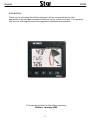
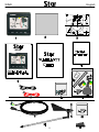
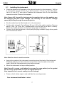
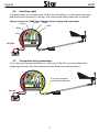
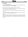
WIND
- Instrument -
Installation and Operation Manual
English
WIND
English
1
English
WIND
Introduction
Thank you for choosing Star Wind instrument. We are convinced that you will
appreciate all the valuable information either you are a cruiser or a racer. It is important
that you are following this instruction regarding installation and operation.
This manual is written for Star Wind instrument
Edition: January 2002
2
WIND
1
2
3
4
5
6
7
8
English
Part specifications......................................................................................................................... 4
Installation...................................................................................................................................... 6
2.1
Installing the instrument .......................................................................................................... 7
2.2
Installing cable ........................................................................................................................ 8
2.3
Connection of log transducer .................................................................................................. 8
Operation........................................................................................................................................ 9
3.1
About this manual ................................................................................................................... 9
3.2
How to use the 4 push-buttons ............................................................................................. 10
3.2.1
MODE........................................................................................................................ 10
1.1.1
DOWN ....................................................................................................................... 10
1.1.2
UP ............................................................................................................................. 10
1.1.3
KEY ........................................................................................................................... 10
1.1.4
Clear.......................................................................................................................... 10
1.1.5
Calibration ................................................................................................................. 11
1.1.6
Lighting...................................................................................................................... 11
3.3
Main function ........................................................................................................................ 12
3.4
Analogue function ................................................................................................................. 12
3.5
Sub-functions ........................................................................................................................ 13
3.5.1
Apparent Wind Speed [AWS] .................................................................................... 13
3.5.2
True Wind Speed [TWS] ........................................................................................... 13
3.5.3
True maximum Wind speed....................................................................................... 13
3.5.4
Velocity Made Good (VMG)....................................................................................... 13
3.5.5
Battery voltage [BAT], option..................................................................................... 14
3.5.6
Boat speed [BSP], option .......................................................................................... 14
3.5.7
Trip log [TRP], option................................................................................................. 14
3.5.8
Water temperature [TMP], option .............................................................................. 14
3.5.9
Trim function for optimum Wind angle or speed, option ............................................ 14
Calibration.................................................................................................................................... 17
4.1
C10 User settings ................................................................................................................. 17
4.1.1
C11 Select the dampening ........................................................................................ 17
4.1.2
C12 Select main information ..................................................................................... 17
4.1.3
C13 Displaying boat speed, trip log and temperature, option.................................... 18
4.1.4
C15 Beep when key is pressed ................................................................................. 18
4.2
C20 Calibration of Log .......................................................................................................... 18
4.2.1
C21 Select unit for speed .......................................................................................... 18
4.2.2
C22 Calibration of log transducer .............................................................................. 18
4.2.3
C23 Unit for temperature ........................................................................................... 18
4.2.4
C24 Temperature offset............................................................................................. 18
4.3
C50 Wind Settings ................................................................................................................ 19
4.3.1
C52 Unit for Wind speed ........................................................................................... 19
4.3.2
C53 Wind speed calibration ...................................................................................... 19
4.3.3
C54 Adjustment of Wind angle.................................................................................. 19
4.3.4
C55-C62 Calibration table for the Wind transducer................................................... 19
4.4
C70 Configure the system .................................................................................................... 20
4.4.1
C74 Demo mode ....................................................................................................... 20
Maintenance and fault finding .................................................................................................... 21
5.1
Maintenance ......................................................................................................................... 21
5.2
Fault finding .......................................................................................................................... 21
5.2.1
General...................................................................................................................... 21
5.2.2
Fault - action.............................................................................................................. 22
5.2.3
Error messages ......................................................................................................... 22
Specifications .............................................................................................................................. 23
6.1
Technical specifications ........................................................................................................ 23
Abbreviations............................................................................................................................... 24
Warranty ....................................................................................................................................... 25
3
English
1
WIND
Part specifications
Star Wind is delivered with all parts for mounting. Check prior to installation.
Wind instrument complete with transducer
Qty.
1
1
1
1
1
1
1
5
5
4
4
1
1
2
1
1
3
1
Description
Reference
Instrument, Star Wind
Instrument front cover
Drill template
Installation and user manual
Warranty card
National distributors list
Power cable, red and black, 3 m (9 ft)
Extra wire protectors, 0,25 mm (1/100”)
Extra wire protectors, 0,75 mm (1/32”)
Mounting screws for the instrument
Round rubber covers
Tube of silicon grease
Connection cover
4-pol screw terminal
Wind transducer Nexus
Mast top cable. 25m (83 ft)
Mounting screws for mast bracket
Mast head bracket
1
2
3
4
5
6
7
8
8
9
9
9
9
9
10
11
12
13
Registering of this product
Once you have checked that you have all the listed parts, please take time to fill in the
warranty document and return it to your national distributor.
By returning this document, it will assist your distributor to give you prompt and expert
attention, in the event of your experiencing difficulties with this product. Keep your proof
of purchase. Also, your details are added to our customer database so that you
automatically receive new product catalogues as and when they are released.
4
WIND
English
WIND
5
English
2
•
1.
2.
3.
4.
5.
6.
WIND
Installation
The installation includes 6 major steps:
Read the installation and operation manual.
Plan where to install the transducers and instruments.
Run the cables.
Install the transducers and instruments.
Take a break and admire your installation.
Learn the functions and calibrate your system.
Before you begin drilling ... think about how you can make the installation as neat
and simple as your boat will allow. Plan where to position the transducers, Server and
instruments. Think about leaving space for additional instruments in the future.
• A few ”do nots” you should consider:
− Do not cut the cables too short. Allow extra cable length at the Server so it
can be disconnected for inspection without having to disconnect all attached
cables.
− Do not place sealant behind the display. The instrument gasket eliminates the need
for sealant.
− Do not run cables in the bilge, where water can appear.
− Do not run cables close to fluorescent light sources, engine or radio transmitting
equipment to avoid electrical disturbances.
− Do not rush, take your time. A neat installation is easy to do.
•
The following material is needed:
Wire cutters and strippers.
Small and large Philips and small flat head screw driver.
Hole saw for the instrument clearance hole 63 mm (2½").
2.8 mm (7/64") drill for the mounting holes in wood.
3.2 mm (1/8") drill for the mounting holes in fibre glass.
Plastic cable ties
If you are doubtful about the installation, obtain the services of an experienced
technician.
The warranty is not valid if you have damaged the instrument by drilling through
the front mounting holes.
6
WIND
2.1
•
English
Installing the instrument
Place the adhesive drill template on the desired location for the instrument. Drill the
7
1
4 screw holes using a 2.8 mm ( /64") drill for wood or 3.2 mm ( /8") for fibre glass.
Use a 63 mm (2½") hole saw to machine the clearance hole for the instrument
connection socket. Remove the template.
Note: Never drill through the instruments 4 mounting holes as the gaskets may
be damaged and thus cause leakage. The warranty is not valid for damage
caused by drilling through the mounting holes.
•
•
•
Run the cable from the Mast head unit to the instrument.
Cut the cable to length. Peel off about 35 mm (1,4") of the cable insulation. Remove
about 6 mm (1/4") from the 3 isolated wires (the 4th wire is an earth / screen).
Attach the 4 cable protectors to the wires using a pair of flat pliers.
Connect the 4 cable protectors to the 4-pole jack plug as shown. Apply silicon paste
on all locations as shown.
Silicon paste
Silicon paste
Note: Must be done to avoid corrosion.
•
•
Apply silicon paste to the instrument connection pins at the back of the instrument.
Press the jack plug onto the instrument pins. Press down the cable in the cable
leads. Mount the connection back cover with the screw.
Mount the instrument in the pre-drilled position.
Note! Use all 4 screws, and tighten the screws (in cross pattern) so the gasket
will be evenly compressed to 1/3 of its original thickness.
Very important for a correct sealing to avoid leakage!
•
Press on the 4 rubber caps to seal and hide the mounting screws.
Your instrument installation is done!
7
English
WIND
2.2
Installing cable
The power cable is connected via a 3A fuse from the battery or at the boats fuse panel
and direct to the instrument or Server. One red and one black power wire is included.
Always connect a 3 AMP fuse between Power supply and instrument.
Screen
Green
Yellow
White
Black
Red
WIND
A B
T L
3A Fuse
2.3
Connection of log transducer
If you have an other log instrument i.e. a Star log or Star Set, you may connect the
single log pulse wire from that instrument to the Wind instrument terminal 4.
WIND
A B
From log instrument,
yellow from transducer
T L
3A Fuse
8
WIND
3
English
Operation
3.1
About this manual
•
Each time a push-button are referred to in this manual, the push-button name will
appear in bold and CAPITAL letters, e.g. MODE.
•
Unless otherwise stated, the push-button presses are momentary.
•
Each time a function is mentioned in the text, it will be in brackets and in the same
format, where possible, as displayed, e.g. [AWA].
•
This manual has been written to be: Compatible with Wind instrument from software
version 1.0.
•
All functions followed by the text option is not valid in a factory set-up instrument.
See calibration to be able to display these functions.
Note!
We have put down a lot of effort in order to make this manual correct and complete.
But since we continuously make our products better, some information can differ
from the products functions. If you need further information contact your national
distributor
9
English
WIND
3.2
How to use the 4 push-buttons
MAIN
FUNCTION
APPARENT
WIND ANGLE
INFOTEXT
TRUE
WIND ANGLE
SUBFUNCTION
TRIM
FUNCTION
KEY
MODE
UP
DOWN
3.2.1
MODE
A press on MODE change the mode of the graphical display. It scrolls
in a circular pattern, one step for every press.
The MODE button is also used to move the cursor when in edit mode.
A press on MODE moves the cursor in a circular pattern, one step to
the right for every press.
A press on MODE and DOWN together, back steps cursor to the
preceding step.
When in editing mode a long press (>2sec) on MODE will escape from
that editing mode.
1.1.1
DOWN
A press on DOWN moves to the next sub-function.
In edit mode it decreases to previous digit.
1.1.2
UP
A press on UP moves to the previous sub-function.
In edit mode it increases to next digit.
1.1.3
KEY
A press on KEY unlocks a digit to access edit mode.
When unlocked, the digits are ”active” (flashes) and can be edited by
pressing DOWN, UP and MODE as required.
When finished editing, lock the digit by another press on KEY.
1.1.4
Clear
A press on DOWN and UP together, clear digits.
10
WIND
English
1.1.5
Calibration
To access calibration mode, press and hold KEY more than 2
seconds.
To return to main function mode, press KEY when the text
return [RET] is shown.
1.1.6
Lighting
The instrument uses red back lighting for the display and the 4
push-buttons. The lighting can be set at 4 different levels.
To access the light control, press and hold MODE for more than
2 seconds. The flashing text [Lit OFF] will be displayed and the
display will be lit momentarily.
To select between the 4 light levels, press UP: [LOW], [MID],
[MAX] and [OFF]. To lock the selected level, press KEY.
11
English
3.3
WIND
Main function
Top data is relative Wind angle, [AWA] (Apparent Wind Angle).
As an alternative to [AWA] the following can be displayed:
[AWS] (Apparent Wind Speed).
[TWA] (True Wind Angle) if the log transducer is connected.
[TWS] (True Wind Speed) if the log transducer is connected.
To change between these functions, see C12, 5.1.2.
3.4
Analogue function
Change Wind scale between 180° and 60° with MODE .
Selected scale is shown with the LCD arrow pointing at scale.
The text [APP] displays selected main function as apparent
Wind angle or Wind speed.
MIX 180°
The text MIX 180° means that both APP and
TRUE Wind
angle is displayed in scale 180°.
MIX 60°
The text MIX 60° means that both APP and
TRUE is
displayed in scale 60.
The scale can be altered between 60° and 180° to get more
accurate readings. At scale 180° each sector represent 5° and
at scale 60° each sector represent 1 2/3°. See the example
below .
WIND
12
WIND
English
3.5
Sub-functions
Select sub-function with UP or DOWN.
Information text for the sub-function is displayed. You may also
”park” your favourite function so it will automatically be
displayed after power on.
Press both MODE and KEY to ”park” the displayed function.
The display will flash once to confirm that you have ”parked”
the function.
3.5.1
Apparent Wind Speed [AWS]
The text [AWS] (Apparent Wind Speed) and its value is
displayed below.
The text [AWS] is toggled with the text [KTS] (KnoTS), [M/S]
(Metres/S) or [BF] (Beaufort).
3.5.2
True Wind Speed [TWS]
The text [TWS] (True Wind Speed) and its value is displayed
below.
The text [TWS] (True Wind Speed) is toggled with the text
[KTS] (KnoTS), [M/S] (Metres/s) or [BF] (BeauFort).
3.5.3
True maximum Wind speed
Press the KEY in the sub-function: [TWS] to display maximum
true Wind speed. After 5 seconds the display will go back to
[TWS] again.
Re-set or clear the [MAX] Wind speed value by pressing UP
and DOWN together or switch off the power.
3.5.4
Velocity Made Good (VMG)
WIND
The text [VMG]
(Velocity Made Good) is displayed with
the actual boat speed towards or
against the Wind.
The water speed information from the
log transducer is needed. The speed
information must be taken from the Star
log if connected. VMG = 0.0 knots when
the true Wind angle is perpendicular to
the boat.
13
English
WIND
3.5.5
Battery voltage [BAT], option
The text [BAT] will display battery voltage. The voltage is
measured inside the instrument and will not compensate for any
voltage drop caused by installation.
3.5.6
Boat speed [BSP], option
The text [BSP] will display boat speed (water speed). The text
[BSP] will toggle with selected unit, i.e. (KTS), (KMH) or (MPH).
As an option, you may add or remove displaying boat
speed [BSP], trip log [TRP] and water temperature [TMP].
See further under calibration.
3.5.7
Trip log [TRP], option
The text [TRP] is displayed and will show trip distance from 0.00
to 99.9 nautical miles, kilometre or miles. After 99.9, 0.00 is
displayed. Clear trip by pressing UP and DOWN together.
3.5.8
Water temperature [TMP], option
The text [TMP] is displayed with water temperature in Celsius or
Fahrenheit.
This function requires a Star log transducer.
3.5.9
Trim function for optimum Wind angle or
speed, option
The text [TRM] and [OFF] is displayed when this function is off.
The trim function can be used as an aid to keep the correct
tacking angle or to discover speed changes caused by sail or rig
trimming.
As the first example we will use [TRM AWA] (TRiM Apparent
Wind Angle).
To trim on Wind angle deviation, select the text:
Press UP and DOWN together, the display will flash. Select
[AWA] with DOWN and confirm with KEY.
Select the level of dampening [d0-d9] and confirm with the KEY.
The default (or latest used) Wind angle is displayed. You may
accept the proposed angle by pressing the KEY or enter a new
Wind angle with UP, DOWN and MODE before confirming with
KEY.
14
WIND
English
The entered Wind angle will be lost when power off. You may
however select a default Wind angle in set-up. See C64 5.4.7.
Every time you select this function, or after power up, the preset value is proposed.
On the display you will see the text TRM and AWA toggling
together with your Wind angle. On the graphic part you will see
your reference angle as one straight horizontal segment when
actual angle is equal to the pre-set angle. At the same time you
will see apparent and true Wind angle.
The deviation is displayed visible upwards or downwards from
the horizontal line to +/-15°. The maximum visible deviation is
15°. When the deviation is between 15° and 30° the 15° sector
is lit. When larger then 30° the segment sector is blanked out.
Trim on speed:
Select the trim function.
Press UP and DOWN together. Select text (BSP) by pressing
UP and confirm with KEY.
Each sector represents 2°
There is a number of different ”speeds” to be used for trimming.
The most common is [BSP] (Boat SPeed) and [VMG] (Velocity
Made Good).
The TBS is normally calculated by use of polar diagram on PC
with racing software. The value ”Target Boat Speed” is
transmitted through the Nexus Server on the NMEA 0183 input.
The Server will then transmit TBS on the Nexus Network.
On the Wind display you will see both the digital value in % and
the graphical value as a 2% variation for each segment.
You may select ”speeds” to TRIM, from this list:
BSP
AWS
TWS
VMG
OFF
Log transducer!
Boat speed
Apparent Wind Speed
True Wind Speed
Velocity Made Good
Function is OFF
Log transducer!
Log transducer!
When [BSP] (or other function) is selected, the dampening [d3]
is flashing. Select dampening level and confirm with KEY.
The text [% OFF] is then displayed to show that the function is
selected, but no reference is yet set.
15
English
WIND
Press KEY to set [BSP] reference.
The display will now show you the text [%] toggling with text
[BSP] or whatever trim you have selected.
The speed variation is expressed in % from set value.
Press the KEY every time you wish to set a new trim reference
value. There is an option to use an external trim button to set a
new trim reference. See more in the calibration.
Each sector represents 2%
16
WIND
4
English
Calibration
To get the most out of your Nexus instrument, it is important to
carefully calibrate the instrument. The calibration values are
stored in a non volatile memory.
To access calibration mode, press and hold KEY more than 2
seconds.
To select a calibration code, press DOWN, UP and MODE as
required.
To return to normal operation mode, press KEY when the text
return (RET) is displayed.
The different calibration routines are divided into five
groups:
C10 - C15 = USR, User settings.
C20 - C24 = BSP, Log transducer and temp calibrations.
C50 - C64 = WND, Wind transducer settings/calibrations.
C70 - C74 = CON, Configuration.
To change a calibration value, press KEY.
To select calibration value, press DOWN, UP and MODE as
required.
To lock the selected value, press KEY.
4.1
C10 User settings
To return to normal mode, press KEY when the text [rET] is
displayed.
4.1.1
C11 Select the dampening
The dampening will affect Wind angle, Wind speed, boat speed
and VMG. Dampening is between d0 (0s) and d9 (1’20).
To change the dampening, press KEY and change with UP or
DOWN and enter with KEY.
4.1.2
C12 Select main information
Select function to be display at the top left of the LCD display.
There is five options.
AWA
Apparent Wind Angle.
TWA
True Wind angle by the use of log transducer.
AWS
Apparent Wind speed.
TWS
True Wind speed by use of log transducer.
17
English
WIND
4.1.3
C13 Displaying boat speed, trip log and
temperature, option
When set to OFF, the functions will be removed from the
display.
4.1.4
C15 Beep when key is pressed
Setting On will make a beep at every key press, while OFF is
silent.
4.2
C20 Calibration of Log
To return to normal mode, press KEY when the text [rET] is
displayed.
4.2.1
C21 Select unit for speed
Unit for speed, knots (KTS), km/h (K/h) or miles/h (m/h).
4.2.2
C22 Calibration of log transducer
Calibration value for speed and distance (1.00 - 1.99).
Drive the boat a measured distance at normal speed.
Compare the distance with the trip counter.
Calculate the value with the following formula.
True distance from the sea chart:
Log trip counter distance:
The current calibration value:
New calibration value:
T
L
C
N
If you suspect a current in the water, drive the boat in both
directions and divide trip counter distance by two.
If the Star Log is already calibrated, you must enter the
same calibration value as for the Star Log.
4.2.3
C23 Unit for temperature
Select degree Celsius [C] or degree Fahrenheit [F].
4.2.4
C24 Temperature offset
By adding a positive or [-] negative value here, it will be added
as an offset before displayed as the temperature.
18
WIND
4.3
English
C50 Wind Settings
To return to normal mode, press KEY when the text [rET] is
displayed.
4.3.1
C52 Unit for Wind speed
Unit for Wind speed [KTS] for (KnoTS), [M/S] for (Metres/S) and
[BF] for (Beaufort).
4.3.2
C53 Wind speed calibration
Do not change this factory setting.
4.3.3
C54 Adjustment of Wind angle
Mast top unit misalignment adjust value or the so called ”Afault”, makes it possible to adjust any horizontal angle.
Example: If the Wind angle is +4° when you sail/drive the boat
straight into the Wind, set the calibration value in C54 to 356°.
4.3.4
C55-C62 Calibration table for the Wind
transducer
In channels C55 to C62 you set the calibration values for the
mast top unit. Each mast top unit is individually calibrated for
best accuracy. See the separate Wind calibration certificate
supplied with each mast top unit. Each of the inter-cardinal
directions are calibrated.
C55
C56
C57
C58
C59
C60
C61
C62
000
045
090
135
180
225
270
315
000°
045°
090°
135°
180°
225°
270°
315°
Set the calibration value according
to the provided calibration certificate
19
English
4.4
WIND
C70 Configure the system
To return to normal mode, press KEY when the text [rET] is
displayed.
4.4.1
C74 Demo mode
The Wind instrument has a built in demonstration mode. All
values are simulated in this mode. It is convenient to learn the
functions of the instrument by using this mode.
Every 7th second the text DEM will appear to alert you that
demo mode is selected.
20
WIND
5
5.1
•
•
•
•
•
5.2
English
Maintenance and fault finding
Maintenance
To clean the instrument, use only mild soap solution and rinse with water.
Do not use detergents or high pressure washing equipment.
At least once a year, check all your connections and apply additional silicon paste at
each connection point.
Always use the instrument cover for protection, when not in use.
Storing transducers and instruments when not in use for longer periods: It is
advisable to remove the instruments and transducers, and store them inside the
boat or at home in room temperature, if possible.
Fault finding
Before you contact your Silva dealer, and to assist your dealer to give you a better
service, please check the following points and make a list of:
• All connected instrument and transducers, including their software version numbers.
• Instrument software version number.
5.2.1
General
In most cases, the reason for faults in electronic equipment is the installation or poor
connections. Therefore, always first check that:
•
•
•
•
•
•
•
•
Installation and connection is made per instructions for instrument and transducers,
(see 2.1).
Screw terminals are carefully tightened.
No corrosion on any connection points.
No loose ends in the wires causing short cuts to adjacent wires.
Cables for damage, that no cables are squeezed or worn.
Battery voltage is sufficient, should be at least 10 V DC.
The fuse is not blown and the circuit-breaker has not opened.
The fuse is of the right type.
21
English
WIND
5.2.2
Fault - action
1. Wind: No reading [ --- ]
• If inaccurate Wind is received, check the connections (separate through deck
connection or below decks connection), are properly made.
• Make sure the transducer is aligned correctly, (see C54, 4.3.3).
• Measure with a voltmeter, at the screw terminal pin 1 and ground, and between pin
2 and ground.
• If the voltmeter shows 1.5 to 4 V DC (minimum Wind speed 3 m/s) at both
measuring points, the transducer and the connections are OK.
• If the voltmeter shows 0 or 5 V DC at both measuring points, the transducer or the
connections are defect. Contact you Silva dealer with this information.
2. Speed and distance functions: No reading [ --- ]
• C13 should be ON. See 4.1.3.
• If you have a voltmeter available, you can check the condition of the transducer.
When measuring with voltmeter make sure everything is connected, that the power
is on and make sure the paddle wheel is rotating.
• At the back of the instrument, measure between pin 4 and ground.
• When not rotating, the value should be fixed at either about 0 or 5 V DC. When
rotating very slowly, by hand, the value should flip between 0 and 5 V DC. When
rotating faster, the value should average around 2.5 V DC.
Irregular values: Check the speed damping (SEA), (see C11, 4.1.1).
5.2.3
Error messages
The following error messages can appear on the display:
ERROR 10
ERROR 11
Range error caused by bad format, e.g. 430°.
Remote command that can not be performed.
If other error messages than the above appears on the Wind instrument, contact your
Silva dealer.
22
WIND
6
English
Specifications
6.1
Technical specifications
Dimensions:
Wind instrument: 110 x 110 mm.
(4.3x4.3 inch)
Instrument cable:
Power supply:
Power consumption
Instrument:
Log- and temp sensor:
Wind transducer:
Temperature range:
Weight:
Enclosure:
12 V DC (10-16 V). The instrument is polarity
protected.
0,08 W
0.8 W (at max illumination)
12 mW
50 mW
Storage: From -30°C to +80°C.( -22°F to 176°F)
Operation: From -10°C to +70°C. (14°F to 158°F)
Instrument: 283 g (9.98 oz).
Transducer: 293 g (10.33 oz).
Instrument. Water proof
CE approval
The products conforms to the EMC requirements for immunity and emission according to
EN 50 08-1,
23
English
7
WIND
Abbreviations
BSP
BTW
C
F
KM
KTS
MH
LCD
LOW
MID
MAX
RET
SOG
TRP
_
Boat Speed
Bearing To Waypoint
Celsius
Fahrenheit
KiloMetre
KnoTS
Miles per Hour
Liquid Crystal Display
LOW
MID
MAX
RETurn
Speed Over Ground
TRiP
Minus
Plus
24
WIND
8
English
Warranty
25
English
WIND
26
WIND
English
27