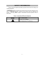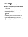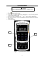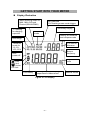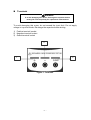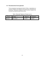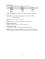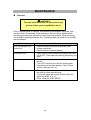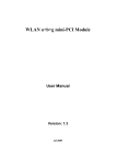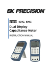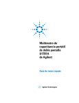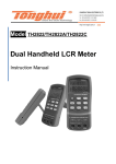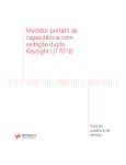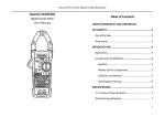
1
Model 830B & 890B Capacitance Meters - II - Limited Three-Year Warranty B&K Precision Corp. warrants to the original purchaser that its products and the component parts thereof, will be free from defects in workmanship and materials for a period of three years from date of purchase. B&K Precision Corp. will, without charge, repair or replace, at its option, defective product or component parts. Returned product must be accompanied by proof of the purchase date in the form of a sales receipt. To obtain warranty coverage in the U.S.A., this product must be registered by completing a warranty registration form on www.bkprecision.com within fifteen (15) days of purchase. Exclusions: This w arranty does not apply in the event of misuse or abuse of the product or as a result of unauthorized alterations or repairs. The w arranty is v oid if the serial number is altered, defaced or removed. B&K Precision Corp. shall not be liable for any consequential damages, including without limitation damages resulting from loss of use. Some states do not allow limitations of incidental or consequential damages. So the above limitation or exclusion may not apply to you. This warranty gives you specific rights and you may have other rights, which vary from stateto-state. B&K Precision Corp. 22820 Savi Ranch Parkway Yorba Linda, CA 92887 www.bkprecision.com 714-921-9095 - III - Contents S AFETY INFORMATION .........................................................................................1 QUICK S TART............................................................................................................3 CAPAC ITANC E METERS ........................................................................................4 INTRODUCTION ...............................................................................................4 GETTING S TART WITH YOUR METER ..............................................................5 DISPLAY ILLUSTRATION..................................................................................5 T ERMINALS .....................................................................................................7 PUSH-BUTTON OPERATIONS ............................................................................8 POWER-ON OPTION ..............................................................................................12 DEMONSTRATE DISPLAY INDICATORS ...........................................................12 DEFAULT FACTORY HI/LO SETTING..............................................................12 HOW TO ENTER S ETUP MODE...........................................................................13 FACTORY DEFAULT.......................................................................................14 BAUD RATE...................................................................................................15 PARITY CHECK..............................................................................................16 DATA BIT......................................................................................................16 ECHO.............................................................................................................17 PRINT ONLY ..................................................................................................17 BEEP FREQUENCY.........................................................................................18 LOCK BUTTONS.............................................................................................19 AUTO POWER OFF.........................................................................................20 BACKLIT DISPLAY.........................................................................................21 BRIGHT LEVEL OF BACK-LIT FOR OFF STATE................................................22 BRIGHT LEVEL OF BACK-LIT FOR ON STATE.................................................23 RESET TO DEFAULT.......................................................................................24 CALC ULATION FUNCTION .................................................................................25 STATIC RECORDING ......................................................................................25 DATA HOLD/ TRIGGER HOLD........................................................................27 RELATIVE (Z ERO).........................................................................................28 T OLERANCE M ODE .......................................................................................30 COMPARE M ODE ( )................................................................................32 REMOTE COMMUNICATION ..............................................................................38 - IV - CAPAC ITANC E MEAS UREMENT .......................................................................40 CALIBRATING THE METER ................................................................................42 INTRODUCTION .............................................................................................42 ENVIRONMENTAL CONDITION .......................................................................42 WARM UP ......................................................................................................42 RECOMMENDEDTEST EQUIPMENT.................................................................43 S PECIFIC ATIONS....................................................................................................44 GENERAL SPECIFICATION..............................................................................44 ELECTRICALSPECIFICATIONS ........................................................................46 MAINTEN ANCE.......................................................................................................47 SERVICE........................................................................................................47 BATTERY REPLACEMENT...............................................................................48 CLEANING.....................................................................................................49 -V- SAFETY INFORMATION These meters are hand-held, battery-operated instruments for testing and sorting capacitors. A WARNING identifies conditions and actions that may cause hazard(s) to the user; a CAUTION identifies conditions and actions that may damage this Device. Following Table-1 explain international electrical symbols used on this meter. Table- 1 International Electrical Symbols DC - Direct Current Caution, risk of danger (See Explanation In The Manual) -1- SAFETY INFORMATION Warnings and Cautions To avoid electric shock, injury, or damage to this instrument and ensure that you use the meter safely, follow the safety guidelines listed below : Read this operation manual completely before using this device and follow all safety instructions. This device is for indoor use, altitude up to 2,000 m. Avoid working alone. Use the device only as specified in this manual; otherwise, the protection provided by the meter may be impaired. Never measure Voltage with this meter. Do not use this device if it looks damaged. Inspect the leads for damaged insulation or exposed metal. Replace damaged leads. Disconnect the power and discharge all high-voltage capacitors before testing. Be cautions when working above 70V DC or 33VRMS and 46.7V peak, such voltages may cause a shock hazard. Always use specified battery. The meter is designed in compliance with EN61010 (IEC1010-1) Installation Category 50V Pollution Degree 2. CE requirement: Under the influence of RF field according to standard, the supplied test leads will pick up induced noise. To have better shielding effect, a short-twisted lead should be used. -2- QUICK START WARNING Read "SAFETY INFORMATION" before using this dev ice. 1. 2. 3. 4. 5. Push to turn on the meter. Push REL to subtract the residual capacitance as not yet insert capacitor into sockets and terminals. Insert the leads of capacitor into "+" and "-" input sockets, respectively. Be sure the polarity for capacitor and remove your hands from capacitor to be tested. Read the display. 1 2 3 Figure- 1 Capacitance measurement -3- CAPACITANCE METERS Introduction These meters are uniquely designed for capacitor sorting and measuring. They are fully auto ranging 11000 count meters. Manual ranging can be selected via the front push button. Main Features: Auto-range, 11000 count resolution and large LCD with dual displa y. Wide range resolution and measurement from 0.1pF to 199.99 mF (50.00mF for model 890B). Visible and audible Tolerance mode assists you to sort the capacitor. Comparison mode with 25 sets for High / Low Limit setting, included non-volatile memory inside, will keep your setting even the power off. Static Recording, you will know maximum, average and minimum values without calculator. Relative mode will help you to calculate the difference between a standard and a measuring value. Data Hold with Manual or Auto Trigger Bi-directional optic computer interface with SCPI commands will assist you to a specialist and make report easier. Low battery indication Brightness LED backlight Safe, precision and speed closed case calibration -4- GETTING START WITH YOUR METER Display Illustration Static recording mode for MAX, MIN, AVG and Present (MAXAVGMIN) DH: data hold “DH” flashing means under trigger. Secondary display “C” flashing for charging capacitor Relative mode Alerting for tolerance and compare mode Auto range Tolerance mode for 1%, 5%, 10%, 20% % is unit for tolerance Unit for Beeper frequency Auto power off Capacitance units : Over High limit : Under Low limit Low battery Primary display (1st display) for capacitance measurement Figure- 2 LCD Displa y -5- Remote control Item Indicator 1) AUTO 2) TOL 1 % 5 % 10 % 20 % 3) 4) 5) 6) 7) 8) 9) 10) 11) 12) 13) 14) 15) DH REL pF nF F mF MAX AVG MIN MAX AVG MIN Description AUTO range Tolerance mode, to set 1%, 5%, 10% and 20% for sorting capacitance. Primary display (1st display). Audible alert for tolerance or compare mode Data hold Low battery indication. Relative mode 1/1000,000,000,000 Farad 1/1000,000,000 Farad 1/1000,000Farad 1/1000 Farad Static recording mode, indicates the present reading Ma ximum reading Average reading Minimum reading 16) Remote control 17) Secondary display (2nd display). 18) Reading out of the HI/LO limits 19) Reading within the HI/LO limits 20) The primary display shows HI limit setting 21) The primary display shows LO limit setting 22) Display the HI/ LO limit set for compare mode. 23) Reading out of the HI limit 24) Reading out of the LO limit 25) % 26) C 27) 28) kHz Unit for tolerance display. Charging period will be flashed, display as discharging period. Enable Auto power off Unit for Beeper Frequency as setup mode -6- Terminals WARNING To av oid damaging this dev ice, discharge the capacitor before testing. Be sure the polarity for capacitance measurement To avoid damaging this meter, do not exceed the input limit. Do not apply voltage to input terminals. Discharge the capacitor before testing. 1) Positive terminal/ socket 2) Negative terminal/ socket 3) Guard terminal/ socket 2 1 3 Figure- 3 Terminals -7- Push-button operations The operation of push-button is shown as below. When push the button, a related symbol will be lit, and the beeper will sound. TOL: Press to set Tolerance mode, and select 1%, 2%, 5%, 10% and 20 %. Press and hold for > 1 Sec. to quit tolerance mode HI/LO: To set or see HI/LO limits as setting mode or compare mode : Press and hold for > 1 Sec. to toggle backlit ON/OFF RANGE: Change measuring range. AUTO: Press and hold for > 1 Sec. to set Auto-range POWER : To turn ON/OFF the meter. HOLD: Freeze measuring value. Press again to trigger next measuring value Press and hold for > 1 Sec. to exit trigger hold. Set: Press and hold for more than 1 sec. to toggle HI/LO limit setting. Push to select which set will be adjusted as setting mode REC: Press to set Static recording mode. Press this button momentarily to cycle through MAX, MIN, AVG and present (MAX MIN AVG) readings at recording mode. Press and hold for > 1 Sec. to quite recording mode. : Push to enter compare mode. Press and hold for > 1 Sec. to quite compare mode. As compare mode, press again to select which HI/LO limits to be compared. Figure- 4 Pushbuttons -8- REL: Set the value on the display to be subtracted. Press and hold for >1 sec. to quit relative mode. 1. : Power ON or OFF This button is used to toggle the power ON or OFF for the meter. Be sure to press button completely to be locked or released. 2. HOLD: Data Hold Press the button to enable the data hold function. The function allows operator to hold the displayed digital value. Press this button momentarily to trigger holding next reading. Press this button for more than 1 second to exit the mode. 3. REC: Static Recording Press "REC" button to enable the recording function. Press "REC" button momentarily to cycle through maximum, minimum, average and present readings. The MAX, MIN, AVG or MAX AVG MIN indicator turns on respectively to indicate which value is being displayed. Press "REC" button for more than 1 second to exit the recording mode. The beeper sounds a tone when a new MAX or MIN value has been recorded. The static recording captures stable values and updates the memory; it will not record the values are “OL” (overload) or below 10 count value. 4. REL: Relative function The function shows the difference between the measured value and the offset reference value. The display may show a non-zero value due to the presence of test leads. You can use the relative function to nullify the residual. Press “REL” button to enable the relative function, and the "REL" sign will be displayed. Press “REL” button again to renew relative value again. Press “REL” button for more than 1 second to exit the mode. The relative function can operate in both auto and manual ranging mode but the function cannot be set when an overload value exists. 5. RANGE: Auto/ Manual Range Press this button to select manual range and turn off the "AUTO" indicator. Press this button momentarily to step up a range at a time. In auto-range, the "AUTO" indicator is lit and the meter will select an appropriate range for resolution if a reading is greater than maximum available range, "OL" (overload) will be displayed on the display. The meter will select a lower range when reading is less than about 9 of full scale. Press this button for more than 1 second to select auto-range. -9- 6. TOL: Tolerance mode With capacitor into the terminals, press the "TOL" button to enable the tolerance mode and set the display value to be a standard reference. The “TOL” indicator will be indicated, and tolerance will be indicated on the secondary display. The meter range is locked also. Press the “TOL” button momentarily again to cycle through 1%, 5%, 10% and 20% tolerance as desire. The alerting sign of “ ” will be indicated accompanying. The beeper sounds a tone while the test value is within the selected tolerance. If the test value is out of the selected tolerance, the beeper will sound three tones. This mode can not be enabled under following condition: a. After setting the recording mode. b. After setting the Compare mode. c. The display shows either OL or below 10 counts. Press and hold this button for more than 1 second to exit tolerance mode. 7. : Compare Mode Press this button to enable the compare mode. The measuring range is locked in this mode. The “ “ indicator will be shown, and the secondary display will indicate “C # #” meaning which set has been used for compare mode. The two right digits indicate current compare set. The “# #” is from 01 to 25. The primary display shows the present measurement. In this state, it is ready for testing. If the reading is out of the high limit (Sign “ “ lit) and the low limit (Sign” “ lit), three tones will be sounded, also the secondary display indicates “nGo”. If the reading is within the high and the low limits, the beeper sounds a tone, and the secondary display indicates “Go”. After 3 seconds or the reading lower than 10 counts, the meter will return to ready state. Press this button momentarily to select different settings for compare. The secondary display will indicate “C01” to ”C25” according to which comparison record has been selected. You can press and hold SAVE button for more than one second to save comparison set for next entry. Press this button for more than 1 second to exit the mode. 8. HI/LO: High/Low limits Press this button momentarily to see the High/Low limit value to be used as compare mode. Press this button to cycle through High limit, Low limit and present values on primary display. The secondary display showed as “H # #”, “L # #” and “C # #” respectively. After 3 seconds without pressing this button again, it will return present value display. In the High/ Low limit setting mode, press this button momentarily to toggle HI and LO limits for adjustment. - 10 - 9. SET: set high/low limits for compare mode Press the SET button for more than 1 second to enter the HI/LO limit setting mode. The secondary display will flash “H01” and the primary display will indicate the value of High limit. Following buttons will be used for this setting mode: a. (LEFT) or (RIGHT): select which digit will be adjusted. b. (UP) or (DOWN): to Increase or decrease the current digit value. c. HI/LO: Select High or Low limit to be set. d. SAVE: Press this button for more than 1 second to store the setting value into the memory. The beeper will sound two tones means the selected value has been stored. If the current setting can’t meet the rule that the high limit must equal or greater than the low limit, the beeper sounds three tones (“BE-BE-BE”). e. SET: Select next compare setting. Press this button momentarily to cycle through L01 (or H01) to L25 (or H25) then come back to L01 (H01) setting. Press the SET button again for more than 1 second to exit the HI/LO limit setting mode. 10. Back-Lit Press this button for more than 1 second to toggle backlit ON/ OFF. Backlit turns off automatically after setting period by setup mode. - 11 - POWER-ON OPTION To select power-on options, press and hold the pushbutton while turning the ON/OFF switch to on position. These power-on options are listed in below table: Table- 2 Power-ON Options PUSHBUTTON DESCRIPTION HOLD Demonstrate Indicators To demonstrate the indicators, the entire indicators will be displayed. Press any button to exit demonstration mode. Reset the high and the low limits to manufacture's default values. RANGE Fast power off test for manufacture purpose REL To see the firmware version Setup mode SET Configure related parameter, please refer to how to enter setup mode for detail. Demonstrate display indicators To demonstrate the indicators, press the HOLD button and turn on the meter simultaneously. All indicators will be displayed. Press any button to exit demonstration mode. Default factory HI/LO setting To set the high and the low limits to manufacture's default values. - 12 - HOW TO ENTER SETUP MODE Press and hold SET button, then turn on the meter from OFF. Release push button when you hear a tone, the meter will enter setup mode then. These parameters will be remained in non-versatile memory even the meter is turned off. You can configure related parameters on setup mode by following procedures: 1. Press (LEFT) or (RIGHT) button to select which menu item to be set. 2. Press (UP) or (DOWN) button to change the parameter. 3. Press “SET” button to select which digit to be adjust, the selected digit will be flashed. 4. Press and hold “SAVE” button for more than one second to save your setting. 5. Push “SET” button for more than one second to exit setup mode. - 13 - Factory Default Following Table describes the outline of the setup menu item and indicates the factory settings. Table- 3 Descriptions for Outline of Setup Menu Item Menu item Factory Setting Selectable Parameters bAUd 9600 Baud rate: 2400, 4800, 9600, 19200 PArt none Parity: odd, e ven or none Data 8-b 8 bits or 7 bits (Stop bit is always 1 bit) Echo oFF Echo: “on” or “oFF” Prnt oFF Print: “on” or “oFF” beep 4800 LbUt oFF Lock buttons, “oFF”: enable pushbuttons “on”: disable pushbuttons AoFF 15 1~99 minutes, “oFF” means to disable auto power off. blit 30 1~99 seconds, “oFF” means to disable turning off backlit automatically. boFF oFF Bright level of backlit at OFF state: oFF~09 bon 09 Bright level of backlit at ON state: oFF~09 dEFA rSt Reset above item to factory original setting. Driving frequency: 4800, 2400, 1200, 600 Hz. “oFF” means to disable beep. - 14 - Baud Rate The baud rate is selected for remote control. It can be set to 2400, 4800, 9600 or 19200. To select your request as follows: Figure- 5 Baud rate setup for remote control - 15 - Parity Check The parity check is selected for remote control. It can be set to none, even or odd bit. To select the parity as follows: Figure- 6 Parity Check setup for remote control Data Bit The data bit is selected for remote control. It can be set to 8 or 7 bits. The stop bit is defined to 1 bit and can’t be changed. To select the data bit as follows: Figure- 7 Data bit setup for remote control - 16 - Echo With ECHO ON, the meter echoes (returns) all the characters whatever it receives. To enable the Echo as follows: Figure- 8 Echo Setup Print only If the remote interface of the meter is under Print-only mode, the meter will print out the measured data when the measuring cycle is completed. The meter will auto send the newest data to a host continuously. The meter doesn’t accept any commands from the host under Print-Only enabled. The remote indicator of the meter will be flashed during operation as Print-only ON. To enable the print-only as follows: Figure- 9 Print-only Setup - 17 - Beep Frequency The driving frequency can be set for 4800, 2400, 1200 or 600. The beeper can be set to ”oFF” as you want kept silent during operation, to select a tone you like according to follows: Figure- 10 Driving frequenc y of Beeper setup - 18 - Lock Buttons The pushbuttons can be disabled by this option. When set to “on”, the pushbuttons will not be operated after turned on the meter. The power-ON option still can be operated as locked the buttons. Figure- 11 Lock buttons - 19 - Auto Power Off The timer for Auto Power Off can be set to 1~99 minutes, “oFF” means to disable auto power off. To set timer as follows: Figure- 12 Auto power saving setup The instrument may automatic turn off within a setting period, if none of the following happens. a. Push buttons are used. b. Static recording is set. c. Auto power off has been disabled by Setup mode. You can toggle OFF, and then turn on again to activate the meter after auto power off, or push any button to wake up. When the meter is to be used for longer period, you may disable the APO. The sign will be turned off when APO disabled. The meter will stay on continuously as the APO is disabled. - 20 - Backlit Display The timer can be set to 1~99 seconds, “oFF” means to disable turning off backlit automatically. The backlight will be turned off automatically after a setting period. To set the period as follows: Figure- 13 Backlit Timer Setup - 21 - Bright level of Back-lit for OFF state This option will help you to set the bright level for off state of backlit. The brightness can be set from “oFF~09”. Figure- 14 Bright level for OFF state - 22 - Bright level of Back-lit for ON state This option will help you to set the bright level for ON state of backlit. It is used to set brightness after turn backlit on. It can be set from “oFF~09”. When you turn backlit on during normal operation, push SET button one time can increase one bright level. The adjusting range is from default to “09” then back default. For example, if you set the level to “05”, you can push SET button to increase the level from 05 06 07 08 09 then back 05 after turned backlit on as normal operation. If the default is “09”, you will not feel any change by pushing SET button. Figure- 15 Bright level for ON state - 23 - Reset to Default Push SAVE button for more than one second to reset the setting to factory default. The setup mode will be set to Baud Rate menu item automatically after finished reset. Figure- 16 Reset to default - 24 - CALCULATION FUNCTION This meter provides operators with various functions including: Static Recording Data Hold/ Trigger Relative Tolerance mode Compare mode ( ) Static Recording The Static recording mode can record the maximum capacitance and minimum capacitance you measured. Further more it will calculate average value you measured. Static recording captures only stable values and updates the memory; the meter will not record which the values are “OL” (overload) or below 10 counts. The operational procedures are described below: 1. 2. 3. 4. 5. 6. Press REC momentarily to enter the static recording. The present value is stored to memories of maximum, minimum and average. The MAX AVG MIN indicator will be lit. Press this button momentarily to cycle through maximum, minimum, average and present readings. The MAX, MIN, AVG or MAX AVG MIN indicator turns on respectively to indicate which value is being displayed. See following Figure. The beeper sounds a tone when a new max or min value has been recorded. Selecting static recording mode as auto range, it will record the value of MAX, MIN or AVG for different ranges. Press REC button for more than 1 second to exit recording mode. The feature of auto power off will be disabled and the " " will be turned off as recording mode - 25 - Figure- 17 Static Recording Mode - 26 - Data Hold/ Trigger Hold The data hold function allows operators to hold the displayed digital value. Press HOLD button to freeze the displayed value and enter manual trigger mode, and the sign of DH will be displayed. Press HOLD button again to trigger another new measuring value updated to display. The sign of DH will be flashed before the new updates. Press HOLD button for more than one second to exit this mode. Figure- 18 Data/ Trigger Hold Operation - 27 - Relative (Zero) The relative function subtracts a stored value from the present measurement and displays the result. 1. 2. 3. 4. 5. Press REL button momentarily to set the relative mode. This sets the display to zero and stores the displayed reading as a reference value and the sign of REL will be displayed. The relative mode can be set at auto or manual range, but can't be set when an overload has occurred. Press REL button momentarily to set the relative mode again When the small capacitance measurement, the display will reads a nonzero value due to the presence of alligator clip leads. You can use the relative function to Zero-Adjust the display. Press and hold REL button for more than 1 second to quit Relative mode. - 28 - Figure- 19 Relative (Zero) Operation - 29 - Tolerance Mode There are 1%, 5%, 10% and 20% tolerance ranges. To enter the tolerance mode, insert a standard value into the socket. Press the TOL button to set display value to be the standard reference. Similarly, the DH value which appears on the primary display can be used as a standard value to sort components. Press TOL button again to cycle through 1%, 5%, 10% and 20% tolerance as desire. The meter range locks as tolerance mode. This mode can not be set under following condition: After setting the recording mode. After setting HI/LO Audible Alert mode. The tested display is either OL or below 10 count. This function is designed for sorting. An audible tone will sound three times when the reading out of the set tolerance. A single tone presents the reading within the selected tolerance. - 30 - Figure- 20 Tolerance Operation - 31 - Compare M ode ( ) This function will help you sort capacitors, and you can set 25 sets of limit ranges. This meter has initial set for High and Low limits, see below table: Comparison Set 1 2 3 4 5 6 7 8 9 10 11 12 13 14 15 16 17 18 19 20 21 22 23 24 25 High limit 100 120 150 180 220 270 330 390 470 560 680 820 1000 1200 1500 1800 2200 2700 3300 3900 4700 5600 6800 8200 10000 Low Limit 90 108 135 162 198 243 297 351 423 504 612 738 900 1080 1350 1620 1980 2430 2970 3510 4230 5040 6120 7380 9000 You can change these sets, please refer to the SET High/ Low limits for detailed description. Also you can use the power-on option to restore factory setting. Following procedures will guide you to set compare mode: 1. Press button momentarily to enter HI/LO Audible Alert mode. The meter locks range in this mode. The “ “ indicator will be indicated, and the secondary display will indicate “C01” to ”C25” which the set - 32 - 2. 3. 4. 5. you saved as last operation. The first left digit means comparison mode. The last two digits indicate current comparison set. The primary display will indicate the present measurement. It is ready to test. Press button momentarily to select different sets. The secondary display will indicate “C01” to ”C25” according to which comparison set has been selected. You can press and hold SAVE button for more than one second to save comparison set for next entry. Press HI/LO button to see the HI or LO value used for comparison and back to the ready mode cyclically. The HI or Lo limits will be briefly indicated on 1st display, and then back to the ready mode. If the reading is out of the high and low limits, the beeper will sound three tones, also the secondary display indicates “nGo”. If the reading is within the high and low limits, the beeper sounds a tone, and the secondary display indicates “ Go”. After 3 seconds the meter will return to ready state. Press and hold the” ” button for more than 1 second to exit audible alert mode. - 33 - Figure- 21 Set Compare Mode - 34 - The following figure shows you the display by compare mode for sorting: Figure- 22 Sorting by compare mode - 35 - Set high/ low limits Using this mode to set the HIGH and LOW limits for compare mode, see the following procedures: 1. 2. 3. Press and hold the “SET” button for more than 1 second to enter the HI/LO limit setting mode. The secondary display will flash “L01” and the primary display will indicate the limit value. Following buttons will be used for this setting mode: a. (LEFT) or (RIGHT): select which digit will be adjusted. b. (UP) or (DOWN): to Increase or decrease the current digit value. c. HI/LO: Select High or Low limit to be set. d. SAVE: Press this button for more than 1 second to store the setting value into the memory. The beeper will sound two tones means the selected value has been stored. If the current setting can’t meet the rule that the high limit must equal or greater than the low limit, the beeper sounds three tones (“BE-BE-BE”). e. SET: Select next compare setting. Press this button momentarily to cycle through #01 to #25 then come back to #01 setting according to High or Low limit. Press and hold the “SET” button for more than 1 second to exit the HI/LO limit setting mode. - 36 - Figure- 23 SET High/ Low Limits - 37 - REMOTE COMMUNICATION This instrument has a bi-directional (full duplex) communication capability. This function will assist user to record and keep data easily. The protocol is provided by SCPI commands (Standard Commands for Programmable Instruments). You can simply use your familiar language to design what application software you want. All commands are combined by ASCII character, non-hexadecimal, which is much user friendly providing. Just configure the measuring range, and then get the measuring value. The detail SCPI for remote operation is accompanied with another file on this CD-ROM. Please refer to. The AK80B accessory includes an optical USB-RS232 cable and a CDROM for PC application software (included with 830B and optional for model 890B). Please refer following procedures if you want to communicate with personal computer: 1. Setup the communication parameters for the meter and the personal computer you used. The meter is default to (9600, n, 8, 1). 2. Be sure that the driver for USB and RS-232 transfer has been installed on your computer. 3. Fixes optic side of cable to communication port of meter, Be sure the text side to be face up. See following figure. 4. Plug the other end of USB terminal of cable into USB port of personal computer. See following figure. To USB port of Computer Figure- 24 Cable Connection for Communication - 38 - 5. Execute the software to take the data as your needs. 6. Always press second snap slightly to remove the cable from communication port of the meter. See the snap as below picture. Always press second snap slightly to remove the cable from communication port of the meter. 7. We don’t suggest you to remove the cover of USB-RS-232 cable. But sometime, you may press snap deeply and pull the cable to cause the cover to be moved out as following picture. To assemble the cover as contrary direction you moved out. Be sure the text side on the cover at same side of inside TOP case. You will hear a click as the cover has been fixed To assemble the cover as contrary direction you moved out. Press the snap and pull the cable to move out the cover - 39 - CAPACITANCE MEASUREMENT Caution To avoid possible damage to the meter or the equipment under test, disconnect circuit power and discharge the capacitor before measuring capacitance. Capacitance is the ability of a component to store an electrical charge. The unit of capacitance is the farad (F). Most capacitors are within the range for nanofarad (nF) to microfarad (μF). The meter measures capacitance by charging the capacitor with a known current, measuring the resulting time of charging period, and then calculating the capacitance. The larger capacitors will take longer time to charge. The sign of “C” flashing means charging capacitor. To improve the measurement accuracy of small value capacitance, press REL with the alligator clip leads open to subtract the residual capacitance of the meter and leads. Measuring tip: For measuring the capacitance more than 1000μF, you can discharge capacitor first and select suitable range to measure it. That will speed up measuring time for get the correct value. 1. Turn on the meter. 2. To keep the open whatever you use sockets, alligator clip leads or SMD tweezers to test capacitance. And then press REL to subtract the residual capacitance of the meter and leads 3. Insert the leads of capacitor into "+" and "-" input sockets, respectively. 4. Be sure the polarity for capacitor. 5. Remove your hands from capacitor. 6. Read the display. - 40 - Figure- 25 Capacitance measurement - 41 - CALIBRATING THE METER CAUTION! TO AVOID DAMAGING THE DEFAULT CALIBRATION DATA S TORED IN A NON-VOLATILE MEMORY, A CALIBRATION TO THE METER CAN ONLY BE DONE BY AN AUTHORIZED SERVICE CENTER AND QUALIFIED PERSONNEL WITH APPROPRIATE EQUIPMENT. FOR DETAIL INFORMATION ABOUT CALIBRATION PROCEDURES, PLEASE CONTACT FACTORY OR AUTHORIZED DISTRIBUTOR. Introduction It is recommended to recalibrate and verify the meter at least once a year to ensure that the original designed performance and specifications. The meter is designed with closed-case calibration capability. It shall calibrate and verify b y remote software with appropriate equipment and qualified personnel only. The related software may be got by factory authorization Environmental condition Calibration or verification test should be performed under laboratory condition which ambient temperature/ relative humidity can be controlled. Warm up Allow up to 1 minutes warm-up at least before performing calibration to the meter. After e xposure or storage in a high humidity (condensing) environment, relative recovery period is required essentially. - 42 - Recommended test equipment The test equipment requirements listed in Table or equivalents are required to perform the calibration and performance verification test procedures. Alternative equipment may be used as long as the accuracy is as good as those listed at least. Table- 4 Standard Equipment Requirements Standard Operating Source Range Capacitance 1nF~10nF Calibrator 100nF~10mF Accuracy Required ± 0.5% ± 0.25% - 43 - Recommended Equipment Fluke 5520A or equivalent SPECIFICATIONS General specification Displa y: 4 1/2-digit liquid crystal display (LCD) with maximum reading of 11000 counts. Automatic polarity indication. Function: Capacitance measurement by DC charge and discharge method. . Visible and audible Tolerance mode assists you to sort the capacitor Min/Max/Average, Data Hold with Manual or Auto Trigger and Relative modes Comparison mode with 25 sets of HI/LO limits can be selected Backlit display for easy reading in the dark. Bi-directional optic computer interface with SCPI commands One-year calibration cycle suggested. Measuring rate (Approx.): 5 times/s for capacitance <100μF. Low battery indicator: The " " appears when the battery voltage drops below 6.0V (approx.). Operating temperature: 0°C to 50 °C (32ºF~122ºF) Storage temperature: -20°C to 60°C (-4ºF~140ºF) without battery Relative Humidity (R.H.): maximum 80% R.H. for temperature up to 31°C decreasing linearly to 50% R.H. at 50°C Temperature coefficient 0.1 * (specified accuracy) / °C (from 0°C to 18°C or 28°C to 50°C) - 44 - Power supply: Single standard 9V Battery can use Alkaline or Carbon-zinc. Battery ANSI/ types NEDA Alkaline 1604A Carbon1604D zinc IEC 6LR61 6F22 Power Consumption: 270(890B) / 375(830B) mVA maximum with backlit Battery life : 80 hours without backlit (approx.) (Based on new alkaline 9V/545mA Battery) Dimension: 41 (H) * 87 (W) * 184 (L) mm Weight: 320 grams with battery/ 430 grams with full package. Standard Accessories: Alligator clip leads, 9V battery, and Instruction manual. Optional Accessories: Communication package, SMT Tweezers and Soft carrying case Safety: Designed in compliance with EN61010-1 (IEC1010-1) for CAT-II 50V, Pollution Degree II Environment. EMC designed in compliance with EN613261. - 45 - Electrical specifications Accuracy is given as (of reading + counts of least significant digit) at 23°C 5°C, with relative humidity Less than 80R.H. Capacitance Range Resolution Accuracy*2 1000.0pF 10.000nF 100.00nF 1000.0nF 10.000μF 100.00μF 1000.0μF 10.000mF 0.1pF 0.001nF 0.01nF 0.1nF 0.001F 0.01F 0.1F 0.001mF 0.01mF 1%+11 1%+6 50.00 mF (890B) 199.99mF (830B) 0.5%+4 1%+6 2%+6 Measuring rate as full scale (approx.) 5 times/sec 5 times/sec 5 times/sec 5 times/sec 5 times/sec 5 times/sec 0.86 times/sec 0.13 times/sec 0.026 times/sec 0.006 times/sec Notes: 1. Overload protection: 250VR.M.S. 2. The accuracy is specified to measure film capacitor or better, and use Relative mode to zero residual first. Specifications are subject to change without notice. For current up-to-date product information, please visit www.bkprecision.com - 46 - MAINTENANCE Service WARNING To avoid electrical shock, do not perform any service unless you are qualified to do so. If the instrument fails to operate, check battery and alligator clip leads, and replaces them if necessary. If the instrument still can’t work, double check operating procedure as described in this instruction manual. When servicing, use specified replacement parts only. Following table will guide you to identify basic problems: Malfunction No LCD indication as power ON Identification Check whether the power button has been locked completely. Check battery or replace battery. No beeper tone Check setup mode whether the beeper has been set to OFF. Then select the driving frequency you want Pushbuttons failure Check whether the meter is under remote control. Turn OFF and then turn ON the meter again. Check the setup mode whether “Lbut” of lock buttons has been set “on”. Failed on Remote control The optical side of cable connected to meter, the text side of cover should be up. Check the baud rate, parity, Data bit, Stop bit (default is 9600, n, 8, 1) Driver install for USB- RS232. - 47 - Battery replacement WARNING Remove all test leads and external adaptor before opening the case. The meter is powered by 9 V battery, be sure to used specified battery. To ensure the specification specified, it is suggested to replace battery immediately as the sign of is displayed and flashing. Following procedures for battery replacement: 1. 2. 3. 4. 5. 6. Remove alligator clip lead and turn off the meter. Release the screw on the battery cover. Slide pull down the battery co ver. Then take up the cover. Replace the specified battery. Reverse the procedure of opening cover to close the bottom cover. Figure- 26 Battery Replacement - 48 - Cleaning WARNING To avoid electrical shock or damage to the meter, do not get water inside the case. To clean the instrument, use a soft cloth dampened in a solution of mild detergent and water. Do not spray cleaner directly onto the instrument, since it may leak into the cabinet and cause damage. Do not use chemicals containing benzine, benzene, toluene, xylene, acetone or similar solvents to clean the instrument. After cleaning, make sure the instrument is dried completely before using. - 49 - □Environmental Condition This Tweeze rs is for Indoor use /Altitude up to 2000m . Operation temperature: 0 C ~40 C (32 F~104 F), R .H. 80%. Storage Temperature: -20 C to 60 C (-4 F~140 F) WARNING! To avoid electrical shock, never use wet Tweezers for your instruments. - 50 - Service Information Warranty Serv ice: Please return the product in the original packaging with proof of purchase to the address below. Clearly state in writing the performance problem and return any leads, probes, connectors and accessories that you are using with the device. Non-Warranty Service: Return the product in the original packaging to the address below. Clearly state in writing the performance problem and return any leads, probes, connectors and accessories that you are using with the device. Customers not on open account must include payment in the form of a money order or credit card. For the most current repair charges please visit www.bkprecision.com and click on “service/repair”. Return all merchandise to B&K Precision Corp. with pre-paid shipping. The flat-rate repair charge for Non-Warranty Service does not include return shipping. Return shipping to locations in North American is included for Warranty Service. For overnight shipments and non-North American shipping fees please contact B&K Precision Corp. B&K Precision Corp. 22820 Savi Ranch Parkway Yorba Linda, CA 92887 www.bkprecision.com 714-921-9095 Include with the returned instrument your complete return shipping address, contact name, phone number and description of problem. - 51 - Printed in Taiwan 2007 B&K Precision Corp. 22820 Savi Ranch Parkway Yorba Linda, CA 92887 USA TEL: 714-921-9095 FAX: 714-921-6422 www.bkprecision.com