1
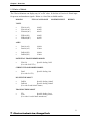
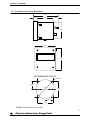
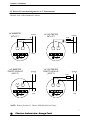
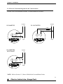
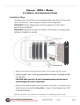
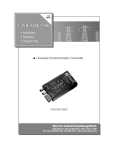
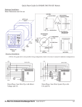
F Series SINGLE-PHASE DIGITAL SWITCHBOARD MONITORS FVA, FVD, FAA, FAD, FF, FT MODELS User's Manual Revision 1.8 June 12, 2015 Doc # E116701 e Electro Industries/GaugeTech 1800 Shames Drive Westbury, New York 11590 Tel: 516-334-0870 Fax: 516-338-4741 E-mail: [email protected] www.electroind.com "The Leader in Power Monitoring and Smart Grid Solutions" F SERIES Address: Electro Industries/GaugeTech Division of E. I. Electronics, Inc. 1800 Shames Drive Westbury, New York 11590 U. S. A For Customer or Technical Assistance, Repair and Calibration: Phone: (516) 334-0870 Fax: (516) 338-4741 E-mail:[email protected] Customer Support & Repair Service Customer support is available 9:00 A.M. to 4:30 P.M., Eastern Time, Monday through Friday. Please have the model, serial number and a detailed problem description available. If the problem concerns a particular reading, please have all meter readings available. When returning any merchandise to E.I.G., an RMA (Return Materials Authorization) number is required. PRODUCT WARRANTY: Electro Industries/GaugeTech warrants this product to be free from defects in material and workmanship for a period of 1 year from date of shipment. During the warranty period, we will, at our option, either repair or replace any product that proves to be defective. To exercise this warranty, fax or call our customer service department. You will receive prompt assistance and return instructions. Send the instrument, transportation prepaid, to the address above. Repairs will be made and the instrument will be returned. LIMITATION OF WARRANTY: This warranty does not apply to defects resulting from unauthorized modification, misuse, or use for any reason other than electrical power monitoring. This unit is not to be used for primary over current protection. Any protection feature in this unit is to be used for alarm or secondary protection only. This warranty is in lieu of all other warranties, expressed or implied, including any implied warranty of merchantability or fitness for a particular purpose. Electro Industries/GaugeTech shall not be liable for any indirect, special or consequential damages arising from any authorized or unauthorized use of any Electro Industries / GaugeTech product. STATEMENT OF CALIBRATION: This instrument has been inspected and tested in accordance with specifications published by Electro Industries/GaugeTech. The accuracy and calibration of this instrument are traceable to the National Bureau of Standards through equipment which is calibrated at planned intervals by comparison to certified standards. DISCLAIMER: Information presented in this publication has been carefully checked for reliability; however, no responsibility is assumed for inaccuracies. The information contained in this document is subject to change without notice. COPYRIGHT: No part of this manual may be reproduced or transmitted in any form or by any means, electronic or mechanical, including photocopying, recording, or information storage or retrieval systems or any future forms of duplication, for any purpose other than the purchaser's use, without the expressed written permission of Electro Industries/GaugeTech, a division of E.I. Electronics, Inc. Copyright (C) 2015 Electro Industries/GaugeTech, Division of E. I. Electronics, Inc. All rights reserved. Printed in the United States of America. TABLE OF CONTENTS F SERIES USER'S MANUAL CHAPTER 1 Section 1.1 1.2 1.3 OVERVIEW Introduction Features Choice of Models 1 1 1 2 CHAPTER 2 Section 2.1 2.2 2.3 2.4 2.5 2.6 2.7 INSTALLATION Easy Installation Installation Requirements Calibration Switchboard Instrument Dimensions Electrical Connection Diagrams for AC Measurements Electrical Connection Diagrams for DC Measurements Recommended Cutout for F Series 4 4 4 5 6 7 8 9 CHAPTER 1 OVERVIEW 1.1 Introduction The F Series family of Single-Phased Digital Switchboard Monitors offers universal applications to a wide variety of industries, including commercial, industrial and power generation. The various models perform a long list of monitoring tasks: Volts Monitor, Amps Monitor, Frequency Monitor, Potential Transformer Monitor, Current Transformer Monitor, DC Shunt Readout and Transducer Readout. Refer to the list of available models in section 1.3. Options include True RMS Readings for AC models (suffix -RMS) and Extended Input Voltage to 600 Volts for FF models (suffix -G). The FF60-1000 models accurately measure frequency using a crystal oscillator and a unique phase lock loop scheme. This technique allows the unit to be calibration free. It also allows the monitor to reject noise on the incoming signal. Because the monitor fits a standard ANSI panel cutout, it provides an easy solution for upgrading or replacing analog switchboard meters. The unit's 12-bit analog-to-digital converter provides superb accuracy throughout the scale, eliminating the chronic problem that analog meters have at the low end. Accuracy for DC Volts and Amps is 0.05% of full scale, ±1 digit; accuracy for AC Volts and Amps is 0.2% of full scale, ±1 digit. Resolution is often critical with a lightly loaded panel. This full 4-digit monitor has a resolution to 9999 counts. The unit updates in 600ms. 1.2 Features Highly Accurate 12-bit Resolution 4-digit Readout Any Scaling 0.8" Super-large, High Output LED's Universal Power Supply Directly Replaces ANSI C39.1 Analog Meters Heavy-duty metal enclosure, electrically protected power supply Frequency Range of 45 - 1000Hz 1 Electro Industries / GaugeTech Doc # E116701 F Series User's Manual Chapter 1 Overview 1.3 Choice of Models The F Series Monitors can display any AC or DC value. It also has a 0-1mA or 4-20mA input for process and transducer signals. Below is a list of the available models: MODELS FULL-SCALE RANGE MAXIMUM INPUT BURDEN VOLTS FVA10 (AC) FVA100 (AC) FVA600 (AC) 9.999V 99.99V 600.0V FVD10 (DC) FVD100 (DC) FVD600 (DC) 9.999V 99.99V 600.0V FAA10 (AC) FAA20 (AC) 9.999A 25.00A FAD10 (DC) FAD20 (DC) 9.999A 25.00A AMPS POTENTIAL TRANSFORMER MODEL FVA120 Specific Scaling 300V (Use with 120V PT's.) CURRENT TRANSFORMER MODEL FAA5 (Use with 5A CT's.) Specific Scaling 10A DC SHUNT READOUT FAD50 Specific Scaling 100mV FAD100 Specific Scaling 200mV (Use with 50 and 100mV shunts) TRANSDUCER READOUT FT1 Specific Scaling 2mA FT20 Specific Scaling 40mA (Use with 0-1 and 4-20mA transducers) 2 Electro Industries / GaugeTech Doc # E116701 F Series User's Manual Chapter 1 Overview FREQUENCY MONITOR FF60 FF400 FF1000 FREQUENCY RANGE 5.0 - 99.99 Hz 50.0 - 999.9 Hz 5 - 9999 Hz FREQUENCY RESOLUTION 00.01 Hz 000.1 Hz 0001 Hz OPTIONS Suffix -RMS Suffix -G True RMS Readings (for AC Models) Extended input voltage to 600 Volts (for FF Models) 3 Electro Industries / GaugeTech Doc # E116701 F Series User's Manual CHAPTER 2 INSTALLATION 2.1 Easy Installation The monitor fits a standard ANSI panel cutout provided in section 2.7 of this manual. Or, use the existing cutout, if you are replacing an existing panel monitor. Large screws on each corner of the monitor are used to secure the monitor to the appropriate panel. The diagrams provided in this chapter show the measurements of the unit and many possible F Series wiring installations. Carefully select the diagram for your monitor and the appropriate configuration. After securing the monitor to the panel, make the electrical connection. The monitor is ready to provide years of accurate readings. 2.2 Installation Requirements Before you install your new monitor, make sure you meet the following installation requirements: Control Power Requirements 115V AC, ±20%; 6VA, 47-440Hz (Suffix 115A) 24-48V DC, ±20%; 6VA (Suffix D) 125V AC/DC, ±20%; 6VA (Suffix D2) Burden Voltage: 0.1VA maximum Current: 0.1VA maximum Operating Temperature -20 to +70 °C 4 Electro Industries / GaugeTech Doc # E116701 F Series Installation & Operation Chapter 2 Installation 2.3 Calibration All switchboard instruments are calibrated at the factory and no initial calibration is required. The unit should not require calibration during the long life of the monitor. If the monitor does require re-calibration, send the unit to the factory for service. EIG can be contacted at the following location: Electro Industries/ GaugeTech 1800 Shames Drive Westbury, NY 11590 (USA) Phone: Fax: (516) 334-0870 (516) 338-4741 website: www.electroind.com e-mail: [email protected] 5 Electro Industries / GaugeTech Doc # E116701 F Series User's Manual Chapter 2 Installation 2.4: Switchboard Instrument Dimensions 4.75 0.875 3.00 0.875 3.95 8-32 4.375 4.375 RECOMMENDED CUTOUT 0.198 DIA. 1.6875 4.00 DIA. 3.375 1.6875 3.375 NOTE: All dimensions are in inches. 6 Electro Industries / GaugeTech Doc # E116701 F Series User's Manual Chapter 2 Installation 2.5 Electrical Connection Diagrams for A.C. Measurements The back view of the instrument is shown. AC AMMETER WITH C.T. SOURCE + AC VOLTMETER WITH P.T. SOURCE FUSE _ _ + _ + LOAD LOAD L L1 L POWER INPUT AC AMMETER DIRECT HOOK-UP (NO C.T.) SOURCE L N AC VOLTMETER DIRECT HOOK-UP (NO P.T.) _ + L L1 POWER INPUT L1 POWER INPUT FUSE _ + L N LOAD SOURCE L N L L1 POWER INPUT L N LOAD NOTE: Refer to Section 1.3, Choice of Models for Fuse Values. 7 Electro Industries / GaugeTech Doc # E116701 F Series User's Manual Chapter 2 Installation 2.6 Electrical Connection Diagrams for D.C. Measurements The back view of the instrument is shown. All measurements are in inches. SOURCE SOURCE - DC AMMETER + + - DC VOLTMETER FUSE _ + L L1 + LOAD L POWER INPUT DC AMMETER WITH SHUNT _ + + - L1 LOAD POWER INPUT SOURCE - + - + _ + L L1 POWER INPUT LOAD NOTE: Refer to Section 1.3, Choice of Models for Fuse and Shunt Values. 8 Electro Industries / GaugeTech Doc # E116701 F Series User's Manual Chapter 2 Installation 2.7 Recommended Cutout for F Series 0.198 DIA. 1.6875 3.375 4.00 DIA. 1.6875 3.375 NOTE: All measurements are in inches. 9 Electro Industries / GaugeTech Doc # E116701 F Series User's Manual