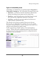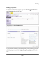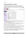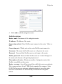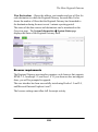
1
MAZU PROFILER
User’s Manual
Version 8
Profiler
Version 8
User’s Manual
© Mazu Networks, Inc
125 CambridgePark Drive
Cambridge, MA 02140
User’s Manual version 8.0-1
ii
Trademarks
The Mazu logo, Mazu Networks, PowerSecure, Profiler, and Enforcer are
trademarks of Mazu Networks, Inc. Other trademarks are the property of
their respective owners.
Copyright
Mazu Profiler Version 8
Copyright © 2007 Mazu Networks Inc. All rights reserved.
Portions of Profiler Version 8 contain copyrighted information of third
parties. Title thereto is retained, and all rights therein are reserved, by the
respective copyright owner. PostgreSQL is (1) Copyright © 1996-2005
The PostgreSQL Development Group, and (2) Copyright © 1994 the
Regents of the University of California; PHP is Copyright © 1999-2006
The PHP Group; gnuplot is Copyright © 1986-1993, 1998, 2004 Thomas
Williams, Colin Kelley; ChartDirector is Copyright © 2005 Advanced
Software Engineering; Net-SNMP is (1) Copyright © 1989, 1991, 1992
Carnegie Mellon University, (2) Derivative Work 1996, 1998-2000, (3)
Copyright © 1996, 1998-2000 The Regents of The University of
California, (4) Copyright © 2001-2003 Network Associates Technology,
Inc., (5) Copyright © 2001-2003 Cambridge Broadband Ltd., (6)
Copyright © 2003 Sun Microsystems, Inc., (7) Copyright © 2003-2004
Sparta, Inc. and (8) Copyright © 2004 Cisco, Inc. and Information
Network Center of Beijing University of Posts and Telecommunications;
Apache is Copyright © 1999-2005 by The Apache Software Foundation;
ILOG JView Component Suite is Copyright © 2003 ILOG, Inc.; Click is
(1) Copyright © 1999-2005 Massachusetts Institute of Technology, (2)
Copyright © 2000-2005 Mazu Networks, Inc., (3) Copyright © 2001-2005
International Computer Science Institute, and (4) Copyright © 2004-2005
Regents of the University of California; OpenSSL is (1) Copyright ©
1998-2005 The OpenSSL Project and (2) Copyright © 1995-1998 Eric
Young ([email protected]); Netdisco is (1) Copyright © 2003, 2004
Max Baker and (2) Copyright © 2002, 2003 The Regents of The
University of California; SNMP::Info is (1) Copyright © 2003, 2004 Max
Baker and (2) Copyright © 2002, 2003 The Regents of The University of
California; mm is (1) Copyright © 1999-2004 Ralf S. Engelschall and (2)
iii
Copyright © 1999-2004 The OSSP Project; ares is Copyright © 1998
Massachusetts Institute of Technology; libpq++ is (1) Copyright © 19962004 The PostgreSQL Global Development Group, and (2) Copyright ©
1994 the Regents of the University of California; Yahoo is Copyright ©
2006 Yahoo! Inc.
Certain Third Party Materials and Corresponding Licenses
In respect of so-called "open source" or "community source" Third Party
Materials only: PostgreSQL and its use are subject to the BSD License;
Netdisco and its use are subject to the BSD License; SNMP::Info and its
use are subject to the BSD License; PHP and its use are subject to the PHP
License; gnuplot and its use are subject to the gnuplot License; Net-SNMP
and its use are subject to the CMU/UCD and the BSD Licenses; Apache
and its use are subject to The Apache Software License, Version 2.0; Click
and its use are subject to the Click License; OpenSSL and its use are
subject to the OpenSSL license and SSLeay license; html2ps and its use
are subject to the Gnu General Public License; libmcrypt and its use are
subject to the Gnu Lesser General Public License; mhash and its use are
subject to the Gnu General Public License; mm and its use are subject to
the Ralf S. Engelschall license; ares and its use are subject to the ares
license; Radius and its use are subject to the Gnu General Public License;
libpq++ and its use are subject to the BSD License; Nessus and its use are
subject to the Gnu General Public License; Yahoo and its use are subject
to the BSD license; graphviz and its use are subject to the Common Public
License.
Individual license agreements can be viewed at the following location:
https://<profiler_name>/license.php
Disclaimers
This manual is for informational purposes only.
Addresses shown in screen captures were generated randomly by
simulation software and used only on an internal network. They are for
illustrative purposes only and are not intended to represent any real traffic
involving any registered IP or MAC addresses.
iv
Table of Contents
Introduction............................................................................................... 1
Overview........................................................................................................................2
Data collected ................................................................................................................3
Alerts .............................................................................................................................4
Traffic profiles ...............................................................................................................5
Host groups....................................................................................................................6
Port groups.....................................................................................................................7
Traffic reporting.............................................................................................................8
User interface.................................................................................................................9
Getting help .................................................................................................................18
Profiler Setup .......................................................................................... 19
Accessing the Profiler user interface ...........................................................................20
General settings............................................................................................................21
Profile periods..............................................................................................................31
Accounts ......................................................................................................................32
Passwords ....................................................................................................................38
User interface preferences............................................................................................38
RADIUS ......................................................................................................................40
Grouping.................................................................................................. 41
Host grouping ..............................................................................................................42
Custom host groups .....................................................................................................43
Automatic host groups .................................................................................................45
Port groups...................................................................................................................47
Port definition ..............................................................................................................48
v
Enterprise Integration ............................................................................ 49
Vulnerability scanning.................................................................................................50
External links ...............................................................................................................54
Host switch port discovery...........................................................................................55
API authorization.........................................................................................................56
Identity sources ............................................................................................................57
DHCP integration ........................................................................................................58
System Verification................................................................................. 63
Profiler information .....................................................................................................64
Data sources.................................................................................................................66
Audit trail.....................................................................................................................73
Alerting .................................................................................................... 75
Overview......................................................................................................................76
Event detection ............................................................................................................77
Rule-based event detection ..........................................................................................78
Heuristic-based event detection ...................................................................................80
Alert generation ...........................................................................................................82
Alerting thresholds.......................................................................................................83
Tuning alerting.............................................................................................................86
Tools for managing alerts ............................................................................................87
Event detection and alerting FAQs ..............................................................................96
Notifications ..............................................................................................................105
Reporting ............................................................................................... 109
Quick reports .............................................................................................................110
Traffic reports ............................................................................................................112
Top Talkers reports....................................................................................................122
Event reports..............................................................................................................125
Event Detail reports ...................................................................................................128
vi
User reports................................................................................................................130
Group Visualization...................................................................................................132
Saved reports .............................................................................................................134
Host information reports ............................................................................................135
Mitigation............................................................................................... 137
Introduction................................................................................................................138
Trusted hosts setup.....................................................................................................143
Switch mitigation setup .............................................................................................145
Router mitigation setup..............................................................................................147
Enabling mitigation plan generation ..........................................................................150
Managing mitigation actions......................................................................................151
Managing mitigation plans ........................................................................................156
The Mazu Sensor................................................................................... 161
The Mazu Sensor .......................................................................................................162
Sensor user interface..................................................................................................163
Basic setup .................................................................................................................174
Traffic analysis ..........................................................................................................187
The Mazu Regional Gateway............................................................... 197
Overview....................................................................................................................198
Regional Gateway setup ............................................................................................200
Data source types .......................................................................................................202
Profiler addresses.......................................................................................................203
Data forwarding .........................................................................................................203
Profiler status .............................................................................................................205
Regional Gateway status............................................................................................205
SNMP MIB Access....................................................................................................206
Password ....................................................................................................................207
Encryption certificates ...............................................................................................208
vii
Network settings ........................................................................................................210
SNMP Support ...................................................................................... 213
Trap summary ............................................................................................................213
Trap variables ............................................................................................................214
Mazu MIB..................................................................................................................230
Interworking with Crystal Reports..................................................... 235
Setup ..........................................................................................................................235
Mazu Expressions ................................................................................. 239
Overview page display expressions ...........................................................................239
Traffic Analysis page display expressions.................................................................240
Mazu Expressions Reference.....................................................................................242
Relational operators (==, !=, >, <) .............................................................................247
Shortcuts ....................................................................................................................248
Profiler Backup and Restore................................................................ 249
Overview....................................................................................................................250
Backup and restore requirements...............................................................................250
Standard Profiler without NAS..................................................................................252
Standard Profiler with NAS .......................................................................................254
Profiler Blade System without NAS ..........................................................................257
Profiler Blade System with NAS ...............................................................................259
Securing the Environment ................................................................... 263
User Role Permissions .......................................................................... 265
Profiler APIs.......................................................................................... 269
Network Traffic API..................................................................................................269
Asset API ...................................................................................................................276
Index....................................................................................................... 281
viii
About This Manual
This manual describes the Mazu Profiler,™ the Mazu Sensor, and the
Mazu Regional Gateway. It assumes that you have a basic understanding
of networking and network management concepts.
The first chapter introduces the main concepts and features of the Profiler
and the Dashboard page, which is the main page of the Profiler user
interface. Subsequent chapters provide more detail on how to use the
Profiler. The final chapters describe the Mazu Sensor and Mazu Regional
Gateway. Supplementary information is provided is several appendices.
Many topics are treated here at a conceptual level. Refer to the online help
system for more detailed information.
This lock icon identifies security notes. A security note cautions you that
the action being described can impact the security of the Profiler.
Your feedback is welcome. Please send your comments about this user’s
manual or the Profiler online help system to [email protected] and
include the product or manual version number. Thank you.
ix
x
1
Introduction
•
Overview
•
Data collected
•
Alerts
•
Traffic profiles
•
Host groups
•
Port groups
•
Traffic reporting
•
User interface
•
Getting help
Introduction
Overview
The Mazu Profiler™ monitors the network to identify activity that
indicates probable intrusions, network problems or policy violations. It
alerts you when it determines that such an event has occurred. You can
then examine the details and determine the appropriate action to take.
The Profiler™ receives traffic information from Mazu Sensors, which
monitor link activity through the use of taps or mirror ports. It also accepts
data from Mazu Regional Gateways and from NetFlow, sFlow, and IPFIX
devices installed at key points in the network. Additionally, it accepts
detailed flow information and application signatures from Packeteer
devices.
Profiler aggregates, de-duplicates, and analyzes the data from all sources.
It groups hosts based on their connection behavior and develops baselines
of what is normal traffic for each host.
Profiler compares current traffic with mathematically derived profiles of
what is typical traffic for the current time of day and day of the week.
Based on the differences, it detects the probable occurrence of network
events. When the severity of a network event exceeds a specified
threshold, Profiler alerts operators to the type, location, and duration of the
event.
Profiler also alerts designated users when a rule-based (user-defined)
event is detected.
Profiler keeps histories and generates reports of alerts for analysis.
Summary and detail reports about events that triggered alerts are displayed
on a web-browsable user interface. Reports can be scheduled, emailed,
printed, exported, and saved.
Profiler can be integrated with management systems, monitoring
equipment, vulnerability scanners, and other network devices.
2
Introduction
Data collected
Profiler collects data from multiple sources, including:
•
•
•
•
Mazu Sensors
Mazu Regional Gateways
NetFlow, sFlow, IPFIX, and Packeteer data sources
Microsoft Active Directory domain controllers (optionally)
Mazu Sensors
Using mirror ports on switches or passive taps on lines, Sensors provide
Profiler with statistics for the following network traffic characteristics:
•
•
•
•
•
Connections between hosts on the monitored segments of the network
Source and destination IP addresses and port numbers used in the
connections
Ports and applications being accessed on hosts
Protocols
Traffic volumes in connections, bytes, or bits per second
When equipped with an optional application sensor module, the Mazu
Sensor also provides Profiler with application traffic information.
Mazu Regional Gateways
The Mazu Regional Gateway is deployed in a local or remote network to
receive traffic data from NetFlow, sFlow, IPFIX, or Packeteer FDR
sources at that location. It aggregates the data, compresses it, encrypts it,
and then transmits it to up to five Mazu Profilers. Additionally, it can
forward this data in its native format to up to five other destinations.
NetFlow sources
In addition to receiving NetFlow data from Mazu Regional Gateways,
Profiler can receive NetFlow data directly from switches, routers, or other
NetFlow-enabled devices.
3
Introduction
Profiler combines and de-duplicates data from all sources to provide
detailed information by hosts, host groups, ports, port groups, and
(optionally) users.
Microsoft Active Directory domain controllers
The optional Profiler user identity feature relies on data obtained from the
security event log of one of more Microsoft Active Directory domain
controllers. This data can be sent directly to the Profiler or it can be read
by a Windows intermediary host that sends it to the Profiler.
The Profiler interprets this data to track successful and failed login
attempts by domain users on hosts within the domain. It associates this
user identity information with host information to produce reports that
identify users as well as hosts.
Alerts
Profiler displays an indication of its alert status at the top of the user
interface window. The alert status is one of the following:
•
OK – The Profiler is operating and no alerts are present.
•
Low – One or more low-severity threats are present.
•
Medium – One or more medium-severity threats are present.
•
High – One or more high-severity threats are present.
•
Unknown – The alert status is unknown when the Profiler is offline.
When an alert status message is displayed, you can investigate the event
that triggered the alert by using the Dashboard page, the Report pages, or
the Quick report box at the top of the page.
4
Introduction
Traffic profiles
Profiler collects traffic data from the monitored network and aggregates it
into traffic profiles. A traffic profile can be created for “business hours” or
“weekends” or any other time periods you want to specify. Each profile is
a mathematically-derived abstraction of the network behavior that is
typical for the time periods it represents. Recent statistics play a larger
role in the traffic profile than older statistics, with each previous time
period having a successively smaller impact on the profile. This allows
Profiler to automatically adjust to changes in network traffic patterns over
time. It is responsive to new conditions, yet retains a historical
perspective of traffic patterns on the network.
Profiler compares new traffic to the corresponding profile to detect
anomalous behavior. The definition of anomalous behavior can be tuned
to accommodate a wide variety of considerations.
The traffic profile is available to use for event detection when Profiler has
collected sufficient data and a user-definable delay time has ended. There
are two types of traffic profiles:
•
•
Recurring profiles
Exception profiles
Recurring profiles are developed from traffic during times that occur every
week, such as Monday from 8:00 AM to 4:59 PM. Exception profiles are
developed from traffic collected during times that occur less frequently
than a weekly schedule, such as ends of quarters or holidays.
Both types of profiles can comprise multiple time period specifications.
For example, a Recurring profile named “Business hours” might be
specified to include traffic from 8:00 AM to 4:59 PM every weekday. An
Exception profile called “Ends of Quarters” might be specified to include
traffic on March 31, June 30, and so forth.
Recurring profiles are useful for tailoring your system to accommodate
known peaks and lulls in weekly traffic. Exception profiles allow you to
treat holidays, quarterly events, or one-time promotional event surges
5
Introduction
differently from normal traffic. Using multiple configurable profiles
allows you to set alerting thresholds more closely without significantly
increasing false positives.
Host groups
After the Profiler has accumulated data for a profile period and can
analyze the connection patterns between hosts, you can initiate a grouping
function that automatically places hosts with similar connection behavior
into the same host groups. You can specify the maximum number of
groups to be formed and select grouping criteria to further control the
grouping function.
Host groups can be identified by user-defined names. For example, you
might give groups names such as:
•
•
•
•
•
•
•
•
•
Desktops
Laptops
Mail servers
Web servers
Database servers
Transaction servers
Routers
Load balancers
Firewalls
The pages under the Grouping page allow you to initiate the grouping or
regrouping of hosts; to add, delete, and rename host groups; and to move
hosts between groups. Additionally, it allows you to define custom
groups.
Custom groups are defined in terms of IP addresses and group names.
You can enter these in the GUI or import a text file containing group
definitions. When you define custom groups, all addresses known to the
Profiler but not assigned to the groups are treated as belonging to the
default “unassigned” group.
6
Introduction
Port groups
Profiler tracks and reports traffic data both by hosts and by ports. You can
define a group of protocol/port specifications, assign the group a name,
and then track and report the usage of ports at the level of port groups
instead of by individual ports.
Reporting port usage by group is especially useful if you have a large
number of hosts involved in a particular business process and it would be
impractical to track port usage individually. Aggregating ports into
manageable groups can make reports easier to interpret. You could have
many port groups for managing many applications, or just a few groups,
such as “encrypted” and “non-encrypted.”
Port groups are also useful when you are using rule-based events.
Assume, for example, that you want to be alerted if a desktop host starts
running a web server. Because web servers typically run on ports 80, 443,
8080, and 8081, you could assign these to a port group called “web” and
then specify a rule to generate an alert when a host from the host group
“desktops” uses ports in the port group “web.”
7
Introduction
Traffic reporting
The traffic reporting feature supports several approaches to creating
reports:
•
•
•
•
Traffic Report page
Quick report box in header
Left-clicking
Right-clicking
Traffic reports can be saved and printed.
Traffic Report page
Traffic can be reported by hosts, interfaces, or applications. Additionally,
an advanced reporting page provides controls for searching profiles or
historical logs for time-series data for specified hosts or ports. Each type
of traffic report provides controls for specifying the time span of the report
and the format of the display.
The report displays produced by all approaches include controls for
changing the subjects and formats of the reports. Up to ten thousand lines
of traffic report data can be exported in comma-separated value (CSV)
files for use with other report generating tools or databases.
Quick report box
The Quick report box appears in the header of each top-level page of the
GUI. If you want a report about a specific entity, you can enter the entity
identifier and value in this box and click Go to produce a report without
specifying a query on one of the Report pages.
Left-clicking
Left-clicking a host or host group generates two lists of traffic volumes.
These are listed by port for:
• ports served by the host or host group
• ports connected to by the host or host group
8
Introduction
Left-clicking a port or port group generates a traffic report of hosts and
host groups providing or consuming services over the port or ports in the
port group.
Right-clicking
Right-clicking a host, host group, port, or port group, displays a shortcut
menu from which you can select reports by various attributes. For hosts,
you can also choose to run a vulnerability scan or generate a Host
Information Report or Users Report.
User interface
The main page in the Profiler user interface is the Dashboard page. The
Dashboard page displays high-level summaries of activity on the
monitored network.
The Dashboard page and all other top-level pages of the GUI include a
header that displays the:
•
•
•
•
Name of the Mazu Profiler whose user interface is being accessed
User name under which the browser session is running
Alert level
Quick report box
To the left of each main page is a navigation bar listing the GUI pages that
you can go to for detailed information, reports and configuration settings.
The privilege level of your user account determines which pages are
available in the navigation bar. Those with Administrator accounts can
navigate to all pages. Those with other types of accounts can access the
pages appropriate to their roles. (Refer to “Accounts” in the Profiler
Setup chapter for a description of account privileges.)
You can show or hide (expand or collapse) the navigation bar by clicking
the small arrow at the top right of the frame. Hiding the navigation bar
provides more display space for information on the Dashboard page.
9
Introduction
10
Introduction
The top-level sections of the GUI available from the navigation bar
include:
•
•
•
•
•
•
•
•
Dashboard
Reports
Alerting
Grouping
Mitigation
Integration
Profiler Setup
System Information
Dashboard page
Profiler is designed to support a wide range of users who may have
different needs and responsibilities. Therefore, the Dashboard page is
highly customizable. You can create multiple customized versions and
switch among them.
The Dashboard page has three main components:
•
•
•
Page controls
System messages
Statistics and events displays (content blocks)
The permissions associated with ones user account determine the actions
that can be taken on the Dashboard page.
Dashboard page controls
There are two display controls on the Dashboard page:
Available pages – The drop-down menu for this field lists the customized
Dashboard pages that are available for viewing. Profiler provides two
default pages:
•
•
Network Operations Dashboard
Network Security Dashboard
These include displays of the information most frequently used by people
in operations and security roles respectively. You can tailor these pages or
11
Introduction
create new pages so that the content of a page is just what you need. You
can make your custom pages available for other users and also use pages
that have been designed by other users. The list of available pages
includes the account name of the owner of each page.
Dashboard Options – The selections in the Dashboard Options dropdown menu allow you to customize and manage the information content
of the Dashboard page.
•
•
•
•
•
Add Content Block... opens a wizard with which you can create a
new display for the page. You can specify the type of information you
want to add by selecting a content block. You specify the format in
which it is to be displayed, the specific kinds of data you want
displayed, time spans it is to cover, and, for certain types of displays,
the data you want to use for comparisons. The wizard creates the
content block and adds it to the page.
Paste Content Block – copies a content block from one dashboard so
you can paste it on to another dashboard. Each content block has a
menu button in the upper right corner. This allows you to copy the
block, edit the display specifications, or delete the block.
If you use the Copy choice on this menu to copy the content block,
you can then use the Page Options menu Paste Content Block choice
to paste the block on to the currently-displayed dashboard or on to any
other available dashboard.
Create New Page... – opens a window in which you can specify the
name and description of a new dashboard. You can specify that this
page is to be private (for your use only) or public (in the Dashboards
list for other users).
Copy Page & Save As... – saves a copy of the dashboard. You are
prompted to enter a name for the saved dashboard. This name is used
to list the dashboard with the other available dashboards.
Edit Page... – opens a window in which you can edit the name and
description of the dashboard and specify whether it is available for
other users (public) or will be listed only on your list of available
pages (private).
12
Introduction
•
Manage Pages... – opens a window in which you can delete
dashboards and specify whether or not dashboards are to be included
in the dashboard selection list.
System messages
System messages provide information and links to additional information.
You can dismiss system messages for the duration of your browser
session. When you dismiss a system message, it no longer appears on the
Dashboard page but continues to be displayed on the System Information
Æ Profiler page. When the system message is no longer pertinent, Profiler
stops displaying it.
When there are more system messages than you want to dismiss
individually, you can use the Dismiss All button to dismiss them as a
group. There are two exceptions to this. The “Welcome ...” message and
the “Profile data collection is now complete...” messages must be
dismissed individually.
Statistics and event displays
You can use the default Dashboard pages as they are or modify them.
They are private to your account, so changing yours does not affect other
users. Alternatively, you can copy a default page and save it as a custom
page with a new name, leaving the default page as it was for future
reference. You can also create a new page and populate it entirely with
content of your own choosing.
There are three types of content:
•
•
•
Top traffic volumes
Watched traffic
Events
Each type of content can be displayed in one or more of the following
formats, depending on which type of data it is:
•
•
•
Table
Pie chart
Bar chart (vertical)
13
Introduction
•
•
•
Bar chart (horizontal)
Line chart
Stacked area chart
When you display information in a table, you can select from a variety of
types of data to display and include only the columns of interest to you.
When you display a Watched content block as a bar chart, you can also
display a comparison with traffic from a previous time span. When
displaying applications as a bar chart, you can exclude unknown
applications so that the display scales to the known applications.
Dashboard page permissions
The following rules apply for viewing, modifying and navigating
Dashboard pages.
•
•
•
•
When a user account is created, the account automatically includes
two Dashboard pages: the Network Operations Dashboard page and
the Network Security Dashboard page. These are private to the
account owner.
Those with Administrator, Operator, and Monitor accounts can create,
modify and delete Dashboard pages and follow links on Dashboard
pages. Those with Dashboard Viewer accounts cannot. They can only
view Dashboard pages. Those with Event Viewer accounts cannot
view Dashboard pages.
Each Dashboard page is owned by the user account in which it was
created. Only the owner can change a page, delete a page, or set a
page to be public or private.
A public page can be viewed by Administrators, Operators, Monitors,
and Dashboard Viewers. It can be copied and saved by
Administrators, Operators, and Monitors, but not by Dashboard
Viewers.
Note: When a page is made public, it does not appear in the Available
pages menu of other users until they make it visible using the Manage
pages option.
14
Introduction
•
When a user account is deleted, all the private pages it owns are
deleted. However, its public pages remain available for other users to
view and copy.
Other GUI pages
The Dashboard is the main or home page. Typically, users start on the
Dashboard page; go to other pages as necessary to run reports, investigate
events, change settings, or check status; and then return to the Dashboard
for routine monitoring.
The other GUI pages are described throughout the remainder of this
manual. The controls, parameter fields and usage procedures for all GUI
pages that are accessible from the navigation bar are described in the
online help system.
In summary, the GUI include the following main pages:
•
Dashboard – main page for monitoring the network.
•
Reports – pages for creating, saving, and viewing reports and
templates for reports.
o Traffic – provides tabs oriented towards generating reports on
hosts, interfaces, and applications. Also includes an advanced
tab for more specific reporting on combinations of categories.
o Top Talker – generates reports of monitored categories of traffic
(hosts, interfaces, applications, etc.) for a specified time span.
o Events – lists events and provides links to Event Detail reports.
o Users – generates reports on user names and last login dates of
users accessing the monitored network. (This page is not
displayed when user identity information is unavailable.)
o Group Visualization – graphical views of connections among the
entities selected for display.
o Saved Reports – lists saved reports and report templates.
•
Alerting – pages for setting up event detection based on heuristics or
user-defined rules, alerting thresholds, and alert notifications.
o Event Detection – sets the values controlling when events produce
alert messages.
15
Introduction
o
o
Rule-based Events – specified rules for a user-defined event type.
Notifications – specifies the destination addresses for email and
SNMP notifications of Profiler alerts.
•
Grouping – places hosts or ports into groups for simpler monitoring.
o Hosts – manages the automatic or manual grouping of hosts into
named groups for ease of monitoring.
o Ports – defines collections of protocol/port specifications so that
they can be tracked and reported as named groups.
o Port Definitions – assigns names to ports for ease of tracking.
This can be used to facilitate port grouping or to define ports
for other purposes.
•
Mitigation – pages for specifying attack mitigation actions and
configuring switches and routers for use in mitigation.
o Plans and Actions – manage mitigation plans and actions.
o Trusted Hosts – identify hosts whose traffic is not to be blocked.
o Switching Setup – identify switches that can be used for blocking
attack traffic.
o Routing Setup – identify routers that can be used for blocking
attack traffic.
•
Integration – pages for integration Profiler with other network
devices.
o Vulnerability Scanning – configures vulnerability scanning to be
performed automatically or manually.
o External Links – configures Profiler for contacting other network
devices for additional information about a host or user of
interest.
o Switch Port Discovery – identifies switches so that Profiler can
determine which switch port a host is using.
o API Authorization – specifies accounts that can access Profiler
via the API.
o Identity Sources – allows you to disable or delete the use of
identity information from selected sources.
•
Profiler Setup – after Profiler has been installed, uses these pages to
prepare for operational use.
16
Introduction
o
o
o
o
o
o
•
General Settings – sets parameters necessary for Profiler to
connect over the network with Sensors, DNS, email servers,
and network-attached storage (NAS) devices. Also sets
parameters for sending to trap receivers and receiving flow
data. Identifies addresses and address ranges to be tracked
individually and what version of MIB browsing to support.
Accounts – enables Administrators to create and modify user
accounts.
Change Password – changes your password. (This page is not
displayed for Administrators, who edit passwords on the
Accounts page.)
UI Preferences – controls the conventions used for displaying
names, addresses, units of traffic measurement, and date and
time formats.
RADIUS – specifies a RADIUS server for authenticating users
that do not have accounts set up on Profiler.
Profiler Periods – defines the time periods for collecting data for
each profile period in the profile scheme.
System Information – provides status information about Profiler, its
data sources, and its users.
o Profiler – displays the status of this Profiler.
o Devices/Interfaces – provides several views of information about
network devices and device interfaces. In the tree view, you
can view detailed information by rolling over an item with your
mouse. In the Interface List and Device List views, you can
review details about all devices known to Profiler. You can
also label device interfaces for easier recognition in reports.
o Audit Trail – provides an audit trail of Profiler usage.
17
Introduction
Getting help
This remainder of this manual describes the Profiler, Sensor, and Regional
Gateway primarily at the conceptual level. For detailed information about
controls, parameter fields, procedures, or technical considerations, refer to
the online help system. This is available from the Help button near the
upper right-hand corner of all top-level GUI pages.
Additionally, several pages have links directly to the help system. All toplevel pages are described under their names or functions in the help
system. Refer to the help system table of contents frame, index, or search
feature.
18
2
Profiler Setup
•
Accessing the Profiler user interface
•
General settings
•
Profile periods
•
Accounts
•
Passwords
•
User interface preferences
•
RADIUS
Profiler setup tasks are assumed to be the responsibility of those with
Administrator accounts. However, users with Operator accounts can
perform all the tasks described in this section except for managing user
accounts.
Profiler Setup
Accessing the Profiler user interface
Profiler can be accessed using a web browser from anywhere on the
network that has access to its address.
Browser Requirements
The Profiler user interface requires a web browser that supports HTML
3.2, JavaScript 1.2, and Java 1.4 or higher. If your browser does not
support these, you will be prompted to upgrade.
The user interface has been successfully tested using Firefox 1.5 and 2.0,
and Microsoft Internet Explorer 6 and 7.
Logging in and out
To log in to the Profiler user interface:
1. Ensure that your computer has network access to the management
interface of the Mazu equipment.
2. Enter the IP address or DNS name of Profiler in your web browser
using https.
3. Log in using the account name and password that were set up for you
during the product installation.
If a user attempts to log in using incorrect passwords too many
consecutive times, Profiler disables logins to the account for specified
time. This lockout is canceled if someone with an Administrator account
assigns a new password to the account.
20
Profiler Setup
Logging out differs from simply closing the browser window in that it
returns you to the log-in page. You can log out as one user and log back
in as another user without having to reestablish a browser session.
To log out of the Profiler user interface, click the Logout button at the
upper right side of the header. This terminates your current user session
and returns to the log in page.
General settings
The Profiler Setup Æ General Settings page includes controls for setting
up:
•
•
•
•
•
•
•
•
Management interface
Time sources
Flow encryption
Data sources
SNMP MIB access
Mail server for alerts and reports sent by Profiler
Inside addresses
NAS (network attached storage)
Changing the Network page requires an Administrator or Operator
account. Changes you make on the Profiler Setup Æ General Settings
page take effect when you click Configure now at the bottom of the page.
If someone were to misconfigure the management interface settings, the
Profiler would become unreachable and it would be necessary to reinstall
the software in order to access it. If other parameters were misconfigured,
the Profiler might not monitor traffic and send alerts correctly. It is
important to the operation of the Profiler for the settings on the General
Settings page to be correct.
21
Profiler Setup
22
Profiler Setup
If you deploy a Sensor on the same subnetwork as Profiler, and if an
intruder can place an unauthorized device on that subnetwork, then a
security risk may exist. Refer to Appendix F Securing the Environment
for a description of securing Profiler against this type of risk.
Management interface configuration
The Management Interface Configuration specifies the name and address
of Profiler. For the Profiler Blade System, this is the address of the
Manager blade. Additionally, this section specifies DNS configuration
and management interface link attributes.
DNS configuration
This section also specifies the names and addresses of the DNS servers
that Profiler accesses to look up the host name associated with an IP
address. If the primary DNS server is unreachable, Profiler uses the
secondary DNS server.
This section specifies the DNS search domain, which is the value that
Profiler appends to DNS entries that are not fully qualified names. For
most people, this is the base name of their company. For example, the
entry for Mazu Networks is mazunetworks.com.
The DNS configuration allows you to protect your DNS server from
excessive traffic loads by limiting the number of host lookups that the
Profiler requests. You can limit the number of lookups for any one table,
graph or list on a report (data set) by specifying the maximum number of
hosts to resolve for an individual data set. The default setting is 100. If
the number of hosts exceeds the specified limit, then the table, graph or
23
Profiler Setup
list reports addresses instead of host names. This setting applies to
Reports pages and the Hosts page.
You can also protect the DNS server by limiting the number of host
lookups in a request. For example, if you specify that the Profiler is to
resolve no more than 1000 hosts simultaneously, then each lookup request
from the Profiler to the DNS server will contain 1000 or fewer addresses
to be resolved.
Leaving the primary and secondary DNS server address fields blank
disables the use of DNS.
Management interface settings
On the Standard Profiler, you can specify the speed, duplex mode, or autonegotiate mode. When you click Configure Now, these values are set into
the management interface. Additionally, the current status of management
link is displayed.
This feature does not apply to the Profiler Blade System, in which link
attributes are configurable only through its chassis management module.
Time configuration
The time configuration specifies the IP addresses of the NTP servers that
the Profiler uses for its time. Alternatively, you can use the Profiler local
clock as the time source. To use the local clock, select the time zone, click
Set System Time, and edit the time and date as necessary.
24
Profiler Setup
Flow encryption
The Flow Encryption section provides controls for generating encryption
certificates and exchanging them with Mazu Sensors or Regional
Gateways.
The controls function as follows:
•
View Current Certificate – opens a window showing the certificate
that Profiler is currently using. This is the certificate that will be
exchanged with Sensors or Regional Gateways. The certificate is
displayed in plain text that can be copied and pasted into a file.
•
Upload New Certificate – opens a window that allows you to browse
to a file to be uploaded. To use a new certificate, you must upload both
the PEM-encoded X.509 certificate file and the PEM-encoded private
key file. When you upload a new certificate, existing Sensor
connections continue to function using the old certificate. However, no
new connections can be established until a certificate exchange is
performed.
•
Generate New Certificate – generates a new encryption certificate for
Profiler to exchange with Sensors and Regional Gateways. When you
generate a new certificate, existing Sensor connections continue to
function using the old certificate. However, no new connections can be
established until a certificate exchange is performed.
•
Exchange Certificates – opens a window in which you can enter an
account name and password for an administrative account on a peer
device in preparation for the certificate exchange. User name and
password fields are provided for each Sensor or Regional Gateway to
which the Profiler is connected.
To exchange certificates with a Sensor, Profiler must log in to a
Superuser account or an Administrator account. To exchange
25
Profiler Setup
certificates with a Regional Gateway, Profiler must log in to an
Administrator or Operator account. The rules for failed login attempts
apply. That is, Sensors and Regional Gateways will lock out the
account after three failed login attempts.
Clicking Exchange in this window executes the exchange of
certificates between Profiler and each configured Sensor or Regional
Gateway it is to use. If a certificate exchange fails, Profiler displays an
alert and reports the status “Certificate exchange failed” to identify the
device on which it failed. If a connection to a Sensor subsequently
fails because of an authentication error after a certificate exchange, an
alert message is displayed on the Dashboard page.
Certificate exchanges can be performed from either the Profiler end of
the link or from the Sensor or Regional Gateway end. You do not need
to perform them from both ends of the link.
Status messages displayed in the Flow Encryption section include:
•
Using default certificate – Profiler is using the certificate that was
preset at the factory.
•
Ready to exchange new certificate – a certificate is ready to be
exchanged with Sensors or Regional Gateways either because you
have generated a new one or because you have uploaded one.
•
Certificate exchange failed – A Sensor or Regional Gateway did not
successfully exchange certificates with Profiler. A status message will
indicate which device did not receive the Profiler certificate or return
its own certificate. Such failures usually result from an incorrect
password or a loss of connectivity with the device.
•
Using custom certificate – Profiler is using a certificate that has been
uploaded instead of using the default certificate or a newly-generated
certificate.
26
Profiler Setup
Data sources
Profiler can be configured to receive traffic information from devices
using NetFlow Versions 1, 5, 7, and 9. If you have more than one
NetFlow source, they must share a common port. IPFIX data should also
use this port.
Profiler can also receive network application classification information
from Mazu Sensors and Packeteer devices. This allows tracking and
reporting of application access and usage.
SNMP MIB configuration
The Profiler MIB can be browsed by external applications and devices.
Profiler supports browsing by both Version 1 and Version 3 clients but can
support only one type of client at a time.
To limit support to SNMP V1 clients, fill out the Location, Description,
Contact, and Community fields. To support SNMP V3 clients, fill out the
authentication and optional privacy information fields instead of the
Community field.
27
Profiler Setup
Authentication and privacy fields
Username: SNMP security name that the application attempting to
browse the Profiler MIB must use.
Authentication passphrase: String that the application attempting to
browse the Profiler MIB must use to authenticate itself to Profiler.
Authentication protocol: Algorithm that Profiler must use to decipher
the authentication passphrase used by the application attempting to browse
the Profiler MIB. This can be MD5 or SHA.
Privacy passphrase: String that the application attempting to browse the
Profiler MIB must use.
Privacy protocol: Algorithm that Profiler must use to decipher the
privacy passphrase used by the application attempting to browse the
Profiler MIB. Profiler uses DES at this time.
Outgoing mail server (SMTP) settings
This section specifies the IP address or name and port number of the mail
server that the Profiler uses when it sends email with alert notifications or
reports. You can also specify a “from” address to ensure that the email is
allowed through a firewall.
The Profiler supports mail server authentication. To use this, click Use
name and password. Then enter the user name and password that the
Profiler is to use to gain access to the mail server.
28
Profiler Setup
Profile settings/inside address configuration
The inside addresses feature allows you to specify a range of addresses
(from /32 to /0) that are to be tracked and reported as individual hosts.
Addresses that are not tracked individually are tracked and reported in
blocks of /8 to conserve system resources.
The default configuration of the Profiler specifies reserved addresses in
the Inside addresses field. If no addresses are specified, the Profiler
tracks all addresses in /8 blocks.
Edit the list in the window as necessary to specify addresses you want
tracked individually.
Notes on address tracking
To enhance performance, the Profiler can track addresses in groups of /8.
Typically, addresses of interest, such as those inside your enterprise, are
tracked individually. All other addresses are tracked in groups of /8 to
conserve storage resources.
Addresses or ranges of addresses in the entire IP address space can be
tracked individually. You are not limited to your internal addresses. You
can also specify suspicious external addresses.
The Profiler operates the same using /8 address tracking as it does using
individual address tracking, except that some statistics may show traffic
volumes for ranges of addresses instead of individual addresses. It is
possible, although not very likely, that you might even see a specification
for a range of addresses appearing as an entry in the Top 20 table of
statistics.
You might notice that a /8 address range overlaps or completely includes a
range or addresses that you have specified to be tracked individually.
However, the two are tracked and reported separately. None of your
29
Profiler Setup
individually tracked traffic will be included in the statistics /8 block, and
vice versa. The /8 traffic will include only traffic that was in the /8 range
but not specified for individual tracking.
NAS Settings
A NAS (network attached storage) device allows you to save more flow
records than Profiler itself can store internally.
The Set up NAS button in the NAS Settings section opens a window for
entering information necessary for Profiler to access the flow logs stored
on the NAS device.
The fields in the NAS Setup window are:
•
•
•
•
IP address – address of the NAS device
Share name – can include slashes but not embedded spaces; leading
slash required
Directory name – can include slashes but not embedded spaces;
leading slash not required
Partition size (GB) – size of the partition in Gigabytes; not less than
35
30
Profiler Setup
Clicking the Test button on the NAS Setup page runs a test to ensure that
Profiler has connectivity to the NAS device and to provide an estimate of
how long Profiler must be off line to copy its flow logs to the NAS device.
If the test fails, you can change what you need to change and run it again.
If the test passes, an Attach button is displayed on the NAS Setup page.
When you click Attach, Profiler copies its flow logs to the NAS device.
After the flow logs have been copied and Profiler is writing logs out to the
NAS routinely, clicking Test on the NAS Setup page tests Profiler
connectivity with the NAS device, but does not display copy time
estimates or the Attach button. Attaching the NAS device is a one-time
operation.
Profile periods
Profile periods are controlled on the Profiler Setup Æ Profile Periods
page. Profiler is shipped with default profiles for weekdays, weeknights,
and weekends. The default Weekdays profile, for example, instructs
Profiler to compare weekday traffic to its computed profile for weekday
traffic.
Operators and Administrators can create other profile schemes. For
example, you could define a recurring profile for days or times of day
when traffic is significantly different from other times, such as Monday
mornings. You can also specify exception profiles to be used on holidays
or during anticipated surges.
Traffic data that is collected during an exception time period is used with
the exception profile and not with the recurring profile. Although
exception profiles and recurring profiles can have overlapping time
periods, only one set of data is collected. Exception profile data collection
takes precedence over recurring profile data collection.
Profiler provides tools for replacing recurring and exception profiles.
These are accessed by clicking Reconfigure Weekly Scheme or
Reconfigure Exception Scheme respectively.
31
Profiler Setup
Accounts
The Profiler Setup Æ Accounts page allows those with Administrator
privilege to add, edit, and delete user accounts and specify global settings
affecting password requirements and login actions. This page does not list
users who can log in to Profiler by having an account on a configured
RADIUS server, instead of by having a Profiler account.
32
Profiler Setup
Account role permissions
To protect the security of the Profiler, Administrators should provide users
with accounts having the permissions appropriate to their task
responsibilities. The Profiler provides five user accounts roles:
•
Administrator – Administrators set up the Profiler on the network, set
up user accounts, monitor Profiler status and usage, and perform
backup operations. A user with an Administrator account can access
all Profiler functionality. Only those with Administrator accounts can
specify mitigation actions, view the user activities log, grant users the
ability to run user reports, specify global account settings, manage user
accounts, and set passwords other than their own.
•
Operator – Operators are responsible for the operational configuration
of the Profiler. This includes managing groups, alerting thresholds,
event detection tuning, traffic reporting and event reporting. Operators
can also modify Profiler network settings and run vulnerability scans.
However, they cannot specify mitigation actions, view the audit trail
page, specify global account settings, or modify user accounts or other
people’s passwords.
•
Monitor – Monitors check the Dashboard page for new events or
unexpected activity. They can run traffic reports and they can view all
top-level GUI pages. But they can change only display settings, and
they cannot modify operational or network settings. The only settings
pages visible to Monitors are UI Preferences and Change Password.
Typically, a user with a Monitor account is in a network operations
center. If a user is authenticated by a RADIUS server instead of by an
account definition in the Profiler database, the user is granted Monitor
permission.
•
Dashboard Viewer – Dashboard viewers can log in and view the
dashboard displays on the Dashboard page. They cannot navigate
away from the Dashboard page except to go to the UI Preferences and
Change Password pages. Additionally, right-click menus and reporting
links are not active for Dashboard Viewer accounts.
33
Profiler Setup
•
Event Viewer – Event Viewers can use their log name and password
to view an Event Detail report whose URL they have obtained from a
network management system. They cannot take any actions on the
event or navigate away from the Event Detail report.
Global account settings
User accounts are managed both globally and by user. Global account
settings control password requirements and log in actions that apply to all
users (except where they can be exempted on individual accounts).
On the Profiler Setup Æ Accounts page, a user logged into an
Administrator account can click Settings... to display the Global Account
Settings page. This page has three tabs:
Password Formatting – specifies password length, case sensitivity, and
requirement for non-alphabetic characters.
Password Aging – specifies the number (from 0 to 8) of previous
passwords Profiler should save and test to ensure that the user is not
recycling a small set of passwords. Also specifies the lifespan of a
password and how much warning users receive before the password
expires. When a password expires, the user is forced to change it upon
their next login.
Login Settings – allows you to:
•
Limit the number of user sessions to one per name/password
combination.
•
Require users of new accounts to change their password on their first
log in.
•
Specify the number of consecutive failed login attempts Profiler
allows before disabling logins for an account.
•
Specify how long logins are disabled on an account after the allowed
number of failed login attempts has been exceeded. If a user needs
access before the lockout period has expired, the Administrator can
edit the account profile to specify a new password for the account.
34
Profiler Setup
•
Specify the path to a splash screen, such as a company banner or
“business use only” statement. Profiler uploads the file and saves it
until it is overwritten by a subsequent splash screen file upload. This
file can be up to 1 Megabyte in size.
•
Specify if the splash screen is dismissed automatically after 5 seconds,
is displayed until the user clicks Acknowledge, or is not displayed.
35
Profiler Setup
New accounts
Administrators should consider the following when creating accounts:
•
Create an account having only the permission level appropriate to the
user’s responsibilities.
•
Follow your organization’s guidelines for password composition and
aging.
•
Use the lowest inactivity timeout value practical for the user role.
•
Require the user to change the password upon the first login.
•
Do not enable database access unless the user requires external access
to the Profiler traffic information database.
•
Do not enable User Reporting unless the user needs to identify other
users by user name.
36
Profiler Setup
RADIUS users
There are situations in which the Profiler administrator may want to grant
people in other areas view-only permission on Profiler. Instead of defining
a Profiler Monitor account for each such user, you can allow their
manager or administrator to grant them Monitor level access to Profiler as
follows:
1. Their administrator enters their names and passwords into a RADIUS
server.
2. You go to the Profiler Setup Æ RADIUS page and set up access to
the RADIUS server.
3. When one of those users attempts to log in to Profiler, they are not
found in the Profiler database of user accounts. Therefore, Profiler
goes to the RADIUS server to authenticate the user.
4. When the user has been authenticated, Profiler logs them on as a
Monitor level user.
You can use multiple RADIUS servers. Profiler tries to authenticate a user
via each configured RADIUS server in the order in which they are listed
on the Profiler Setup Æ RADIUS page.
37
Profiler Setup
Passwords
All users except Event Viewers and Administrators can change their own
passwords on the Profiler Setup Æ Change Password page.
Administrators can replace the password on any account by using the
Profiler Setup Æ Accounts Æ Edit feature. Therefore, the Change
Password page is not displayed on Administrator accounts.
User interface preferences
The UI Preferences page controls the display conventions that apply
generally throughout the user interface for a specific user. Settings
include:
Refresh rate – specifies the rate at which to refresh the data on the GUI
pages. The default is once per minute, which is the lowest rate.
Host name resolution – chooses one, both, or neither of the following
options:
•
Resolve host names for hosts with static IP addresses – looks up the
host names associated with hosts that have static IP addresses. Note
that this option requires Profiler to access a DNS server. This is
controlled by the Enable DNS name resolution for hosts option on
the Management Interface Configuration section of the Profiler Setup
Æ General Settings page.
38
Profiler Setup
•
•
Resolve host names for hosts managed by DHCP – looks up the
host names for hosts whose IP addresses are assigned dynamically by
DHCP. This requires Profiler to be configured to receive DHCP
information. Traffic reports by host display the last known host name
associated with a host.
Suppress DNS search domain () from resolved hosts – suppresses
display of the domain names for hosts in the DNS search domain. If
no DNS search domain is specified in the Management Interface
Configuration section of Profiler Setup Æ General Settings page,
then all resolved hosts are displayed by their fully qualified names.
Based on your knowledge of your environment (for example, host name
changing as a result of a recent equipment redeployment, your DHCP
server not yet integrated with Profiler, etc.), you can choose the options
that work the best for your reporting needs.
Host group – which type of host group is to be displayed in event reports
and traffic reports when the reports are set to display host group
membership.
Data Unit – units in which statistics are displayed wherever traffic
volume is displayed in terms of bandwidth; bytes or bits.
39
Profiler Setup
Print/Email – maximum number of rows for printed and emailed tables.
Date Style – convention for displaying days, months, and years.
Time Style – 12-hour or 24-hour time display.
RADIUS
The Profiler authenticates users when they log on. The primary means of
authentication is the Profiler local database. If the Profiler does not find
the user information in its local database, it checks a RADIUS server, if
you have configured one.
If the Profiler can authenticate the user through the RADIUS server, it
allows the user access, but only at the monitor level. Users authenticated
through a RADIUS server can view Profiler displays related to traffic
volumes and connections. However, they cannot view user identity
information or change the Profiler configuration, user settings, or their
passwords.
If the Profiler cannot obtain user information in its local database or from
RADIUS server, then it denies access to the person attempting to log on.
40
3
Grouping
•
Host grouping
•
Custom host groups
•
Automatic host groups
•
Port groups
•
Port definition
Grouping
Host grouping
The Profiler enables you to manage traffic by groups of hosts. It can
automatically assign hosts to host groups on the basis of similarities in
their connection behavior. Additionally, you can define custom host
groups based on your own categories, such as departments or locations.
Both automatic and custom groups can be tracked and reported. This
allows you to view traffic statistics aggregated by host behavior or by
organizationally meaningful categories.
Host groups are managed on the Grouping Æ Hosts page. Grouping
control is provided at three levels:
Group Types – The Group Types pane of the Hosts page provides
controls for running automatic grouping and for creating, modifying, or
removing custom groups and group types.
Groups – The Groups pane lists all automatic groups when Automatic is
selected in the Group Types pane. When a custom group type is selected
in the Group Types pane, the Groups pane lists all the groups that have
been defined for the selected custom group type.
In this pane you can select an automatic or custom group and view its
members and its traffic profile. Additionally, you can add, delete, and
rename automatic groups.
Members – Selecting a group in the Groups pane and clicking View
Members lists the members of the selected group in the Members pane.
You can select a member of this group and view its traffic profile.
If the members are listed by host name, you can resolve the names of
selected hosts into their IP addresses. Multi-selecting (Control + click) is
supported.
42
Grouping
Custom host groups
Generally, the steps involved in establishing custom groups are:
1. Go to the Grouping Æ Hosts page and create a group type. This
involves assigning a group type name defining the groups of that type.
You can either import custom group definitions from a file or enter the
definitions manually.
2. Optionally, check the groups by viewing the traffic profiles of the
groups, viewing lists of members of groups, and viewing the traffic
profiles of individual members of groups.
Refer to the online help system for detailed information about working
with groups.
43
Grouping
Defining custom groups
You can define custom groups of up to ten group types. There can be
many groups of each type.
You define custom groups by entering their IP addresses and the group
names in the Create by hand pane of the Create custom group type
page or else in a text file, which you then import. Custom group
definitions must be formatted as follows:
ip_prefix_1 group_name_1
ip_prefix_2 group_name_2
...
ip_prefix_n group_name_n
where ip_prefix is either an IP address and prefix in CIDR format or an
individual IP address in dotted decimal format, and group_name is the
name of the group. Unneeded characters are not included in the CIDR
format. For example,
10/8 group1
172.168.1.1 group2
192/8 group1
In this example, both 10/8 and 192/8 are assigned to group1.
Note: If you use overlapping IP address ranges in the custom group
specifications, the Profiler assigns a host to the custom group whose
specification has the longest matching prefix. For example, if you are
specifying custom host groups corresponding to network segments “net-a”
and “net-b,” a specification file containing:
•
•
10.0.0.0/8 net-a
10.15/16 net-b
will cause an address such as 10.15.16.23 to be assigned to the net-b
group.
44
Grouping
Automatic host groups
The automatic grouping feature groups hosts based on their connection
behavior. Hosts that have similar connection behavior are placed into the
same group. Each group is automatically assigned a name based on the
most frequently used port (e.g., http, smtp) and role (client or server).
The result of running the automatic grouping feature is a list of host
groups in the format port name – role – group ID. You can fine-tune the
groups to optimize alerting and reporting by adding or deleting members
and assigning more descriptive names.
Generally, the steps involved in establishing automatic host groups are:
1. Run automatic grouping.
2. Either automatically commit the results of the grouping process or
view the results before committing them.
3. Optionally, view the results, edit the proposed group names to be
consistent with the way you want to report network traffic. Then
commit or discard the proposed groups.
4. Optionally, check the groups by viewing the traffic profiles of the
groups, viewing lists of members of groups, and viewing the traffic
profiles of individual members of groups.
5. Optionally, rename groups, move hosts from one group to another, add
groups, or delete groups.
6. When new hosts are detected and appear in the “unassigned” group,
add them to the existing groups.
Grouping and regrouping
Initial Grouping
When the Profiler is initially started, no host groups are assigned. The
normal practice is to wait until the Profiler has collected a representative
45
Grouping
sample of the hosts on the monitored network and then initiate the
automatic host grouping process.
The completion of profile data collection is indicated by the System
Message on the Dashboard page or System Information Æ Profiler page.
When profile data collection is finished, you can click Run automatic
grouping to display the page on which you specify how grouping is to be
run.
Regrouping
When you re-run the automatic host grouping function after you have
specified alerting thresholds for individual host groups, the new host
groups are not associated with any alerting rules. Therefore, when the
new grouping results are committed, any existing alerting rules that
include previous host group definitions in their specifications are
automatically modified to avoid conflicts or ambiguities. The names of
previous host groups are replaced with “Any” where they existed in the
alerting rules. The alerting rules are otherwise preserved so that you do
not have to completely re-specify them. However, if you want an alerting
rule to apply to particular new host groups and not to others, you should
edit the rule to replace “Any” with the names of the new groups.
Otherwise, the rule will be applied to any group that matches the other the
parameters. It is recommended that you consider the impact of this before
regrouping.
46
Grouping
Port groups
In addition to reporting traffic volumes in terms of hosts, Profiler can track
and report traffic in terms of ports being used. Where a large number of
ports are involved, it can be useful to define collections of protocol/port
specifications that can be tracked and reported as named groups. The
Grouping Æ Ports page allows you to create, edit, and delete groups of
ports for tracking and reporting.
Profiler recognizes the port names that are defined on the Grouping Æ
Port Definition page. These are standard IANA names by default.
However, you can modify the definitions or import your own services file.
47
Grouping
Port definition
The Port Definition page allows Operators and Administrators to:
•
•
•
•
•
•
View a histogram of the traffic volumes of selected ports or all ports
that are using TCP or UDP or both.
Add new ports to the list of ports that the Profiler knows by name.
Rename ports. The ports tracked by default correspond to the standard
services defined by the Internet Assigned Numbers Authority (IANA).
Import a standard /etc/services file so that the Profiler displays and
reports use your custom names for ports.
Specify ports as being server ports.
Identify which ports have been assigned to Port Groups.
48
4
Enterprise Integration
•
Vulnerability scanning
•
External links
•
Host switch port discovery
•
API authorization
•
Identity sources
•
DHCP integration
Enterprise Integration
Vulnerability scanning
Profiler provides the client side of vulnerability scanning. You must install
vulnerability scanning software on a server that is accessible to Profiler in
order to manage scanning from the Profiler GUI.
Profiler provides both manual and automatic vulnerability scans of hosts
on the network. You can initiate a scan manually by right-clicking a host
IP address on any report in Profiler and choosing Vulnerability Scan on
the shortcut menu. Alternatively, you can click Run Scan on the
Integration Æ Vulnerability Scan page. You can also set Profiler to
automatically initiate a scan in response to any specified traffic event of
any specified severity.
Two types of vulnerability scans can be defined: Quick scans and Deep
scans. The Quick scan is intended to use a shorter list of plugins and
perhaps simpler options than the Deep scan. However, their configuration
and operation is otherwise the same. Both can be run while you wait or
run in the background. Also, they can be run from different scan servers.
Vulnerability scan reports are saved in the Completed Reports table of the
Reports Æ Saved Reports page. They can be viewed, printed, and
emailed. They can also be saved indefinitely, like other reports.
Vulnerability scan reports are subject to the same disk space management
rules as other reports.
The running of vulnerability scans is recorded in the audit log, which
Administrators can view on the System Information Æ Audit Trail
page.
50
Enterprise Integration
Types of vulnerability scans
Vulnerability scan configurations are specified using the Integration Æ
Vulnerability Scanning page. The Vulnerability Scan page has three tabs:
•
Quick Scan – specifies the connection information, authentication
method, and settings for the scanner used for a Quick Scan.
•
Deep Scan – same fields and buttons as the Quick Scan tab, except
that it specifies the configuration required for a Deep Scan.
•
Auto Scan – specifies the event types and alert levels that are to
trigger automatic vulnerability scans.
The setup tabs for the Quick scan and the Deep scan are the same.
However, they are independent of one another. You can, for example,
have Quick scans performed by a scanner running on one scanner server
and Deep scans performed by another scanner.
Profiler supports Nessus, Rapid7, Qualys, nCircle and Foundstone
scanners. Profiler offers more configuration options for Nessus than for
the others because the other scanning systems are configured primarily
through their own user interfaces.
51
Enterprise Integration
Configuring automatic scans
After specifying the Quick Scan and Deep Scan parameters, you can set
Profiler to automatically run scans in response to specified alerts.
The Vulnerability Scan Setup page lists the type of network events that
cause Profiler to send traffic-related alerts. For each level of alert these
events can trigger, you can specify a scan action to be taken: No Scan,
Quick Scan, or Deep Scan.
Fields near the bottom of the page provide for limiting the volume and rate
of scanning to protect your network from being overwhelmed by scan
traffic. Profiler reports up to 256 hosts involved in an event. It runs up to
4 scans concurrently and up to 12 scans per hour.
The scan traffic is recorded in the Profiler flow logs and becomes part of
the traffic profile.
52
Enterprise Integration
What is scanned
The event that triggers an automatic scan also determines which hosts are
scanned, as follows:
Type of event that triggered scan
What is scanned
Denial of Service/Bandwidth Surge
Attacker hosts
Host Scan
Scanner host
New Host
New host
New Server Port
Host that provided or consumed a
service over the port
Port Scan
Victim hosts
Rule-based Event
Source and destination or client
and server hosts involved in the
event.
Suspicious Connection
Source and victim
Worm
Victim hosts
Only hosts identified as having “inside addresses” are scanned. Inside
addresses are specified on the Profiler Setup Æ General Settings page.
Manually initiating a vulnerability scan
Operators and Administrators can manually initiate a vulnerability scan by
either of two methods:
•
Click Run Scan on the Quick Scan tab or Deep Scan tab of the
Integration Æ Vulnerability Scanning page.
•
Right-click the host on a report and choose Vulnerability scan on
the shortcut menu.
53
Enterprise Integration
You can add more hosts if you want to scan hosts in addition to the one
you right-clicked, for a total of up to 256.
Note: Manual scans are not subject to the rate limit on the Auto Scan
tab. However, they are counted towards the limit when the next
automatic scan runs.
When a scan run in the background is complete, a scan report is
automatically saved in the Completed Reports table of the Reports Æ
Saved Reports page. Reports from foreground scans appear
automatically and can be saved, printed, and emailed. The content and
format of a report are determined by the type of scanner you are using.
Refer to your scanner documentation for descriptions of the information
contained in the reports. The appearance of a report may vary from the
appearance of the report available from the scanner GUI, depending on the
scanner used.
External links
Profiler provides a means for contacting other network devices for
additional information about a host or user of interest. Right-clicking a
host and choosing an external link from the shortcut menu passes a query
on the IP address of the host to the other network device. A new browser
window opens to display the response from that device.
Likewise, right-clicking a username and choosing an external link from
the shortcut menu passes a query on the username to the other network
device and opens a new browser window to display the response.
External links must be specified on the Integration Æ External Links
page in order to be available on the right-click menu. They must be
specified using the syntax that the external device expects. Refer to the
online help system for syntax examples.
54
Enterprise Integration
Host switch port discovery
As part of the Host Information Report, Profiler identifies the switch port
to which a host is connected. This requires Profiler to know about the
switches that the host’s traffic passes through. Profiler attempts to find the
outermost switch on which a host was seen. If it knows about all the
switches, then this will be the access switch and Profiler will report the
port to which the host is connected.
The Integration Æ Switch Port Discovery page allows you to identify
your switches to Profiler so that the host switch port information will be
included in the Host Information Report.
55
Enterprise Integration
API authorization
The information that Profiler collects about network assets and traffic
flows is made available for use by other products through APIs
(application program interfaces). Management systems and other
programs can send requests for information to Profiler. Profiler will
respond by sending the HTML data for fully formatted traffic reports or
XML data for asset reports.
Access to the APIs is protected by ACLs (access control lists). The
Integration Æ API Authorization page provides fields for specifying a
list of API users.
The API Authorization page is available to Administrators and Operators.
Changing or deleting an ACL specification does not affect users that are
currently logged in until they log out.
An NMS or other remote system can use an automated script to request
Event Reports from Profiler as follows:
1. The requesting system extracts the URL of the Event Report from the
event trap that it receives from Profiler.
2. The script adds the user name of its Event Viewer account on the
Profiler to the URL in the format
&username=event_viewer_account_name.
56
Enterprise Integration
For example, the URL
https://core1.mazunetworks.com/event_viewer.php?&id=1234&username=noc1
will connect to the Profiler Event Viewer account named “noc1” and
obtain the Event Report for event 1234.
Identity sources
When the Identity option is enabled, Profiler collects user identity
information to use for reports on network users. Identity sources are listed
on the Integration Æ Identity Sources page.
Profiler receives the identity information from Microsoft Active Directory
domain controllers. These are configured separately from the Profiler
setup and administration activities.
Once configured with Mazu’s connection utility, the Active Directory
devices send user identity information to Profiler. You can configure
Profiler to use or ignore this information. For example, if a source
produces too much data or data that is not interesting, you can configure
Profiler to ignore identity data that it receives from that source.
If a source is no longer being used, you should disable the collector utility
at the source so that it stops sending data. Then delete the entry for that
source from the list on the Integration Æ Identity Sources page.
57
Enterprise Integration
DHCP integration
If parts of your network are managed by DHCP address allocation, then
host machines may be assigned new IP addresses when their leases expire.
In order to develop and display the profile of a host’s activity, Profiler
must continue to track the connection behavior of the host when its IP
address lease expires and the DHCP server assigns it a new IP address.
Profiler uses lease information from the DHCP server as the basis for
tracking hosts. This requires a mechanism for transferring lease
information from the DHCP server to Profiler. The specifics of the
mechanism depend on the DHCP implementation. Mazu provides
Integration Notes for several popular DHCP packages.
Lease data file format
The Profiler accepts DHCP data in two formats.
Alcatel-Lucent QIP-compatible format
This format contains one lease record per line in the following order:
IP Address | MAC address | DNS name | domain | lease-start date time | leaseend date time | status
For example (on one line):
192.168.10.1|aa:bb:cc:dd:0a:01|host-10-1|example.com
|2007-05-01 15:26:15Z|2007-05-08 15:26:15Z|Active
Note that time stamps are expected to be in UTC format. To specify time
stamps in local time, use the “20070501 15:26” format instead:
For example:
192.168.10.1|aa:bb:cc:dd:0a:01|host-10-1|example.com
|20070501 15:26|20070508 15:26|Active
58
Enterprise Integration
ISC-compatible format
This format is compatible with POSIX-compliant DHCP packages
distributed by Internet Systems Consortium, Inc. (www.isc.org).
lease 10.128.2.219 {
starts 2 2006/08/15 16:09:09;
ends 2 2006/08/15 20:09:09;
tstp 2 2006/08/15 20:09:09;
binding state free;
hardware ethernet 00:02:a5:ba:53:9b;
uid "\001\000\002\245\272S\233";
}
lease 192.168.255.100 {
starts 1 2007/02/19 01:28:33;
ends 1 2007/02/19 13:28:33;
tstp 1 2007/02/19 13:28:33;
binding state free;
hardware ethernet 00:04:23:c4:02:30;
}
Transfer mechanism
When transferring DHCP lease data to the Profiler from a DHCP package
that uses one of the data formats Profiler supports, you can transfer the
data in its native format to the Profiler.
When integrating with a Windows DHCP domain controller, you need to
convert the data format. Mazu provides a conversion script and
instructions for its use. You can download these from the Profiler help
system.
Typically, the transfer of lease information to the Profiler is implemented
as follows:
1. Enable the DHCP server to log in to Profiler via SSH. SSH on the
Profiler must be configured with the public key of the DHCP server.
On the Profiler, SSH configuration files are in /usr/mazu/var/dhcp/.ssh.
Mazu supports SSH v2.
59
Enterprise Integration
2. Set up a script on the DHCP server so that every n minutes, a client
process obtains lease information from the DHCP server and writes it
into a file. In the case of a Windows DHCP implementation, use the
Mazu script to convert the data format before transferring the file to
the Profiler.
3. Set up a scheduler to execute the scripts to dump, convert (if
Windows), and transfer the DHCP lease data information to the
Profiler.
If the Profiler receives an IP address in flow data that does not appear in
the lease data file, it assumes the address to be static.
Mazu Networks provides integration notes with instructions for integrating
Profiler with QIP, ISC, Infoblox, and Windows DHCP software.
Update intervals
The interval for updating Profiler DHCP information can be based on
DHCP lease times, lease update intervals and the times when new leases
are most frequently requested on your network. A DHCP client on a
network with no outages may update its lease when half the lease time has
expired. That is, it obtains a new lease at an interval of lease-length/2.
This can vary widely, depending on network conditions and security
policies. Some general guidelines for sending Profiler new DHCP data are
as follows.
•
If your script for sending DHCP information to Profiler sends
incremental updates (i.e., just what has changed since the last update),
have it send Profiler updates every hour.
•
If your script sends complete DHCP lease information for every
update, have it send Profiler updates based on the length of the leases,
as follows:
60
Enterprise Integration
Lease length
Profiler update interval
More than 4 days
1 update per day (around 10:00 AM)
4 days
2 updates per day
24 hours
6 updates per day
12 hours
12 updates per day
6 hours
24 updates per day
Less than 6 hours
24 updates per day
61
Enterprise Integration
62
5
System Verification
•
Profiler information
•
Data sources
•
Audit trail
System Verification
Profiler information
The System Information Æ Profiler page lists the status of the Profiler.
On a Profiler Blade System, this page lists the status of each mBlade.
The page also lists:
•
•
•
•
•
•
•
•
•
•
•
total number of hosts
currently loaded profile
start and end times of the available traffic flow logs
start and end times of the available identity information logs
DNS server status
Certificate status for encrypted links with other Mazu devices
Mitigation status
NTP server status
active user sessions by name, address, login time, and last access time
system messages
tracked applications
The System Information Æ Profiler page provides information that can
be used for security audits. This includes:
•
•
•
•
Certificate information – The dates for which the Mazu link
encryption certificates are valid and the common name of the issuer.
Timestamp accuracy – The Time Difference column in the NTP
Server Status section displays the difference between the time used
by the Profiler and the time obtained from the NTP Server (if one is
specified). Depending on network conditions, the Profiler is normally
synchronized to the NTP source to within a few milliseconds. A
significant time difference will impact the timestamps for events
reported by the Profiler.
Current usage – The Active User Sessions section identifies who is
logged on, when they logged on, and when their last activity occurred.
Tracked applications – Applications that are currently known to the
Profiler. Flows containing these applications are counted and
64
System Verification
displayed by application. Traffic for applications not identified in this
list is marked as Unknown.
65
System Verification
Data sources
Profiler reports its sources of traffic data on the System Information Æ
Devices/Interfaces page. Using list entries or mouse-rollover pop-ups,
this page provides the following information for devices and their
interfaces from which Profiler is receiving data:
Devices
• Status
• IP address
• Device type (in terms of what type of data is being sent)
• NTP synchronization (Mazu Sensors and Mazu Regional Gateways
only)
Device Interfaces
• Status
• IP Address:Index of interface
• Interface name (as assigned on the data source device)
• Interface label (as assigned on Profiler)
• MAC address
• Interface type (e.g., Ethernet CSMA/CD RFC3635)
• MTU (maximum transmission unit)
• Traffic rate (traffic in bits per second that Profiler tracks)
• Utilization (percent of device speed that Profiler currently sees being
used)
Much of this information must be obtained from the data source devices.
For devices that send data directly to Profiler, Profiler uses SNMP to
obtain the information. For sources that send data to Mazu Regional
Gateways, the Regional Gateways use SNMP to obtain the information.
They then send it to Profiler.
You can specify which version of SNMP and what community name
Profiler or Regional Gateways use to contact the devices. You can assign
labels to interfaces. Profiler uses these labels when displaying interface
information.
66
System Verification
The data source devices must be configured to send data (Netflow, sFlow,
IPFIX) to the Profiler or Regional Gateway. When Profiler receives data
from a device, either directly or via a Regional Gateway, it automatically
lists the device IP address, name, type, and status on the System
Information Æ Devices/Interfaces page.
Profiler or the Regional Gateways then attempt to obtain the detailed
information using SNMP. Both use the default settings for SNMP unless
you have specified other settings.
The information and controls for monitoring and labeling data sources are
displayed in three views of the System Information Æ
Devices/Interfaces page:
•
•
•
Device/Interface Tree
Interface List
Device List
Device/Interface Tree view
The format of the System Information Æ Devices/Interfaces page
Device/Interface Tree view displays data source information in the
following format:
Mazu Sensor
Interface
(Device entry line 1)
(Interface entry line)
Mazu Regional Gateway
Data source device
Device interface
Device interface
(Device entry line 1)
(Device entry line 2)
(Interface entry line)
(Interface entry line)
Third-party device (Netflow, sFlow, IPFIX)
Device interface
Device interface
(Device entry line 1)
(Interface entry line)
(Interface entry line)
67
System Verification
Device entry line 1 identifies the Mazu Sensor, Mazu Regional Gateway
or third-party device that is sending data to Profiler.
Device entry line 2 is used in the case of Regional Gateways to identify
the devices that are sending data to the Regional Gateways.
The Interface entry lines provide information about each of the devices
interfaces.
Rolling you mouse over the device name or one of its interfaces displays a
summary of information about each.
Mazu Sensor and Mazu Regional Gateway device names are linked to the
login pages of the respective Mazu device. Other controls and indicators
on the System Information Æ Devices/Interfaces page Device/Interface
Tree view include:
Status indicator
Color represents status, as described in the legend. The status color is
propagated upward. That is, when the display is collapsed, the status of the
parent entry shows the status of the most degraded child entry.
68
System Verification
Edit links
On device entries, the Edit link opens a window in which you can edit the
SNMP settings that the Profiler or Regional Gateway use when contacting
the data source devices and their interfaces. Refer to the SNMP Settings
topic below.
On interface entries, the Edit link opens a window in which you can edit
the interface label that Profiler uses when displaying information about the
interface.
Delete links
If a device or interface is no longer carrying traffic, you can delete the
entry for that device. If the device resumes sending traffic information, it
will automatically be added to the list.
Interface List view
The System Information Æ Devices/Interfaces page Interface List view
displays the following information about each interface of the data source
devices with which Profiler can communicate:
•
•
•
•
•
•
•
•
•
•
•
•
Status (as explained by the color legend on the right side of the page)
IP address
Host name
Index of the interface
Name of the interface (as defined on the device)
Label (which you can define on this page)
MAC address of the interface
Type of interface
Type name
MTU (maximum transmission unit)
Speed (bits per second)
Utilization (percent of maximum bandwidth utilization)
69
System Verification
Device List view
The System Information Æ Devices/Interfaces page Device List view
displays the following information about each data source device with
which Profiler can communicate:
•
•
•
•
•
•
•
Status (as explained by the color legend on the right side of the page)
IP address
Host name
Type of data
NTP Synchronization (Mazu Sensors and Regional Gateways only)
SNMP version that Profiler is to use for obtaining information
SNMP community name that Profiler is to use
Additionally, this page allows you to configure the default SNMP settings
that Profiler uses to retrieve device information from data source devices.
70
System Verification
SNMP settings
Click the Global Settings link to display a window in which you can
specify the default SNMP version number and community name. Profiler
uses this setting for contacting all data source devices whose SNMP
Version field is set to Default on this page.
Each device can be identified as using the default settings or SNMP
Version 1 or Version 2. When a setting for a Regional Gateway is
changed, the change is automatically applied to the settings for all devices
that are sending data to that Regional Gateway. However, you can change
the setting for any individual device.
Assume, for example, that you have a Regional Gateway that is set to use
the Default SNMP settings when obtaining device information from each
of four devices that are sending it NetFlow data. If you change the SNMP
setting for the Regional Gateway to V2, it will automatically switch to
using SNMP Version 2 for contacting all four NetFlow devices.
Continuing this example, you could subsequently set one of the four
NetFlow device entries to V1. In this case, the Regional Gateway would
use Version 1 to communicate with that device and Version 2 to
communicate with the other three.
Configuring data source devices
To configure Profiler to receive both traffic information and device
information from other devices:
1. Set up each of the devices to send data to the Profiler or to a Regional
Gateway. Use the IP address of mBlade1 on a Profiler Blade System
or the IP address of the management interface on a Standard Profiler or
Regional Gateway.
2. On the Profiler Profiler Setup Æ General Settings page, go to the
Data Sources section and specify the types of data to be received and
the port on which each type of data is to be received. IPFIX data uses
the same port as NetFlow data.
71
System Verification
3. Go to the System Information Æ Devices/Interfaces page and select
the Device List view.
4. Click Global Settings and ensure that the version number and
community name are set to the values you expect to use for contacting
all or most data source devices.
5. If Profiler is receiving data from a Regional Gateway in a region that
does not use the default SNMP settings that you just specified, then set
the SNMP Version and SNMP Community values for that Regional
Gateway to the version number and community name that you expect
to use for contacting most or all data source devices that are sending
data to that Regional Gateway.
6. If any individual devices that require a version of SNMP different
from what you specified as the default, go to the entry for that device
and set the SNMP Version and SNMP Community values as
required.
7. When all SNMP settings are configured as required, click Apply.
8. Choose the Interface List view on the System Information Æ
Devices/Interfaces page.
9. If desired, assign labels to individual device interfaces by entering text
in the Label field of the entry for each interface.
10. Click Apply (in the lower, right-hand corner of the Interface List
view).
11. Choose the Device/Interface Tree view on the System Information
Æ Devices/Interfaces page and check the display of the data source
devices and their interfaces.
72
System Verification
Audit trail
The System Information Æ Audit Trial page reports Profiler usage and
is available only to Administrators. The report can be limited to a
specified time frame and to particular user activities, user accounts, and
users who have logged in from specified IP addresses or ranges.
The Activities box limits the audit report to any of the following user
activities:
•
•
•
•
•
All
Login/Logout
Accounts
Setting change
Mitigation
73
System Verification
•
•
•
•
Notification change
Recipient change
Vulnerability scan
Email sent
For some types of changes, the old and new values are listed on this page.
For others, depending on the type of change, links are provided to pages
listing the old and new settings.
The Accounts box limits the audit report to a selected user account.
The IP address box limit the report to the activities of users who have
logged in from the specified IP addresses or address ranges.
The Run now link generates the audit report and displays it on the page.
74
6
Alerting
•
Overview
•
Event detection
•
Rule-based event detection
•
Heuristic-based event detection
•
Alert generation
•
Alerting thresholds
•
Tuning alerting
•
Tools for managing alerts
•
Event detection and alerting FAQs
•
Notifications
Alerting
Overview
Profiler alerts you to significant network events by performing the
following steps:
1. Network monitoring - receives traffic information from any
combination of a variety of sources. Aggregates, de-duplicates and
processes traffic data to prepare it for network behavior analysis.
Builds profiles of typical network behavior for specified times.
The types and sources of data collected from the monitored network
are specified on the Profiler Setup Æ General Settings page in the
Data Sources section. Information about the devices from which
Profiler is receiving data is provided on the System Information Æ
Devices/Interfaces page.
2. Event detection - analyzes network behavior using heuristics-based
event detection rules and user-defined event detection rules. Assigns
each event a severity rating number based on the likelihood of it being
a threat to network availability or security.
3. Alert generation - checks the severity of each event against a set of
user-defined alerting rules. When the severity of an event exceeds a
user-defined alerting threshold, Profiler alerts users to the existence of
the event by indicating an alert condition and displaying information
about the event.
4. Notification - automatically sends email alert messages to designated
recipients. Sends SNMP messages to designated security or operations
management systems.
5. Event reporting - saves details of all events that triggered alerts.
Event detail reports can be viewed on the Profiler user interface or
retrieved by remote management systems for analysis. Refer to the
next chapter for descriptions of reporting.
76
Alerting
Event detection
An event is the occurrence of network behavior that may threaten the
integrity or performance of the network, or violate an organizational
policy. Profiler uses two approaches to detecting network events:
•
Heuristic-based event detection – Profiler compares the current
behavior of the network to an automatically updated profile of
behavior that is typical for the current time of day, time of week, time
of month, time or year, etc. It analyzes the relationships between
current network behavior and typical network behavior. This involves
a wide range of parameters, some of which are user-definable.
Profiler heuristically determines whether or not an event is occurring
and, if an event is in progress, what type of event it is and how severe
of a risk it poses to the network. Based on this analysis, Profiler
assigns the event a severity number from 1 to 100. The severity is
compared to a user-defined alerting threshold to determine if the event
should generate an alert.
•
Rule-based event detection – Profiler compares current network
behavior to a user-defined event detection rule. If any measurement of
network behavior meets the conditions of the rule, Profiler determines
that the event has occurred and assigns the event a severity number
from 1 to 100.
Unlike the heuristic-based events, in which the severity number may
depend on several aspects of the network behavior, the severity
number of a rule-based event remains what you set it to when you
defined the rule. The severity is compared to a user-defined alerting
threshold to determine if the event should generate an alert.
77
Alerting
Rule-based event detection
A rule-based event is an event that is triggered when the conditions of a
user-defined event detection rule are satisfied. Rule-based events differ
from the standard set of Profiler heuristic-based events in that they
compare traffic to absolute values that you specify, whereas the standard
event detection heuristics compare current traffic to profiles of typical
traffic. Additionally, the severity of a rule-based event remains as you
assigned it; it is not adjusted upward or downward in response to traffic
conditions.
When Profiler detects a rule-based event, it tests the severity level of the
event against the alerting thresholds for rule-based events. If the severity
of the event exceeds the Low, Medium, or High alerting threshold, then
Profiler displays an alert message.
Common uses of rule-based events include generating alerts when:
•
•
•
Connections occur within specified time periods.
Any connection using a specified port occurs (even if only one
packet).
An upper or lower limit for traffic of a specific type is exceeded.
A rule-based event is defined on a worksheet page available from the
Alerting Æ Rule-based Events page. This page lists all rules that have
been defined. It provides links for creating a new rule and for viewing,
editing, deleting, copying, and enabling or disabling an existing rule.
The alerting threshold for a rule-based event is set on the Alerting Æ
Event Detection page.
78
Alerting
Pre-defined Rule-based Events
Profiler is shipped with the following rule-based events (RBEs) defined
but not enabled:
•
•
•
•
•
Firewall Tunneling Activity – detects tunneling activity that may
pass through common firewall holes.
P2P Application Activity – detects P2P applications.
P2P Port Activity – detects suspicious activity involving TCP and
UDP ports commonly used by P2P networks.
Spambot Activity – detects spam activity from your email servers to
the external network.
Tunneled Application Activity – detects suspicious application
tunneling.
You can examine the definition of each of these by going to the Alerting
Æ Rule-based Events page and clicking View in the entry for the rule of
interest.
These pre-defined Rule-based Events should not be enabled until host
grouping has been performed. (Refer to the chapter on grouping.)
79
Alerting
Heuristic-based event detection
For heuristic-based event detection, Profiler compares the current behavior
for the network to a profile of typical network behavior. If the difference
between current behavior and profiled behavior exceeds the limit for any
of a number of parameters, Profiler recognizes the behavior as a network
event, and assigns a severity level to the event.
Profiler uses heuristic-based event detection to detect the following types
of events:
•
DoS/Bandwidth Surge – significant increase of traffic that conforms
to the characteristics of a Denial of Service attack.
•
Worm – increase in connections that typically results from the spread
of a worm. Profiler traces these connections over time through the
network to identify how the worm spreads from infected hosts to new
hosts.
•
Host Scan – hosts on the monitored network are being pinged.
•
Port Scan – ports of a host are being tested for running services or
being in a “listening” or “accepting” state.
•
Suspicious Connection – communication between two hosts that have
been on the monitored network for some period of time, but which do
not normally communicate with one another (for example, an
Engineering department host connecting to a Finance department
host).
•
New Host – a host that has not been seen before has joined the
network.
•
New Server Port – Profiler has discovered that a host or group of
hosts is providing or using a service over a port that is new to that host
or group of hosts.
80
Alerting
Additionally, Profiler detects Sensor Problem events:
•
Sensor Problem – a Sensor that had been communicating with
Profiler is no longer reachable, or Profiler is attempting to
communicate with a Sensor but is not receiving data in the expected
format (for example, not time synchronized), or an interface on the
Sensor is down. You can select which of these is reported.
All event detection heuristics except for the New Server Port heuristic are
pre-set to values that have been found to be generally useful. However,
you can tune the event detection heuristics to optimize performance for
you network.
Heuristic-based event detection rules can be enabled, disabled, and tuned
from the Alerting Æ Event Detection page. Alerting thresholds for event
detection rules are also specified using this page.
Enabling and disabling event detection
Event detection can be enabled, disabled, and tuned using options on the
Alerting Æ Event Detection page as follows:
•
Event detection for each event type can be enabled or disabled
individually by selecting the event type and clicking the ON-OFF
toggle button.
81
Alerting
•
Settings that affect all event detection rules of a particular event type,
including rule-based events, are available (where applicable) by
selecting the event type and clicking the Advanced settings for
selected event... button.
•
Settings that affect all heuristic-based event detection are available by
clicking the Global event settings button.
Global event settings
New Host Delay – When a new host appears on the network, it is not
immediately included in event detection (except for rule-based events).
After the host has been on the network for the number of days specified, it
is included in event detection.
Global Event Delay – You can delay heuristic event detection when
Profiler is restarted. Allowing a week for Profiler to collect a new traffic
profile reduces the number of alerts reported while Profiler is initially
characterizing network behavior.
Plan generation threshold – Profiler automatically generates a mitigation
plan when the mitigation feature is used. To conserve system resources,
you can set Profiler to generate mitigation plans for only events with a
severity high enough to warrant mitigation.
Alert generation
An alert is a notification to an operator or management system that a
network event of interest has occurred. Profiler provides alerts in the form
of:
•
SNMP notifications – Profiler sends SNMP traps or notification
messages to specified network management systems. The management
system receiving the notification might display messages or send email
itself. It can obtain a URL from the message, which allows it access to
a report of the event that triggered the alert.
82
Alerting
Management systems that will be retrieving Event Detail reports from
Profiler based on URLs attached to SNMP notifications should be
given a user account and added to the access control list on the
Integration Æ API Authorization page.
•
Email notifications – Profiler sends email notifications to designated
users or management systems.
•
Alert level status displays – Profiler displays a “High,” “Medium,” or
“Low” alert indication in the header at all top-level GUI pages. The
alert indication is displayed in the header until the alert condition no
longer exists or is temporarily suppressed (“snoozed”).
The alert notification mechanisms are described further in the
“Notification” section that appears later in this chapter.
Profiler generates an alert when the severity of an event exceeds a low,
medium or high alerting threshold.
Thresholds can be set for individual hosts, address ranges of hosts, host
groups, ports, and interfaces. You can tailor the thresholds based on
expected behavior.
You can also define multiple alerting rules for an event type so that the
occurrence of an event in one group of addresses or ports produces a
higher level of alert than the same type of event in another group. For
example, you may want a higher level of alert for suspicious connections
to your financial servers than for suspicious connections to your desktops.
Alerting thresholds
An alerting threshold is specified in terms of an event severity. When the
severity of an event equals or exceeds an alerting threshold, it causes
Profiler to send an alert.
There is a default alerting threshold rule for each event type that has
adjustable severity levels. (The Sensor Problem event type does not use
alerting thresholds.)
83
Alerting
The default rule specifies the severity levels that must be reached or
exceeded to trigger Low, Medium and High alerts. However, you can
restrict particular alerting thresholds to specified source hosts or host
groups, destination hosts or host groups, or both, depending on the type of
event.
You can add, modify, remove and reorder alerting threshold rules using
the Alerting Æ Event Detection page using the buttons and the up- and
down-arrows. The Event Detection page also links to pages for advanced
tuning of the heuristics that detect events and assign severity levels to
events.
Alerting threshold rules
For each event type that has an alerting threshold, you can set Low,
Medium, and High alerting thresholds for:
•
•
•
individual hosts
CIDR blocks of hosts
host groups
Additionally, you can set alerting thresholds that are limited to hosts that
use or provide services over specific ports. Port-based alerting thresholds
are available for the following event types:
•
•
•
•
•
Denial of Service/Bandwidth Surge
Worm
Host Scan
Port Scan
Suspicious Connection
For each event type that supports alerting thresholds, you can set different
alerting thresholds for different hosts or host groups. For example, assume
that you set the default alerting threshold for an event type to trigger a low
level alert when the severity of an event of that type reaches or exceeds
60. Then you add a rule specifying that, if any traffic involved in an event
of that type is in the range of 10.0.0.0/16, Profiler should send a Low level
alert when the event severity reaches 40.
84
Alerting
The result of this will be that an event with the severity of, for example, 50
will trigger a Low level alert only if traffic in the range of 10.0.0.0/16 is
involved. If all traffic involved in the event is outside this range, the
Profiler will not send an alert until the event severity is 60.
Requirements for matching an alerting rule
In order for an event to match an alerting rule,
•
If the alerting rule specifies source hosts, then all source hosts in the
event must be within the source host specification of the alerting rule.
•
If the alerting rule specifies destination hosts, then all destination hosts
in the event must be within the destination host specification of the
alerting rule.
•
If the alerting rule specifies ports, then all ports in the event must be
within the port specification of the alerting rule.
If “sources,” “destinations,” or “ports” is not applicable for the type of
event for which the alerting rule is specified, it is treated as “Any.”
Precedence of alerting threshold rules
When you create multiple alerting threshold rules for an event type, each
rule appears in the Alerting Thresholds list on the Event Detection page.
Profiler checks the severity of events of that event type against each rule
in the list in the order in which the rules appear in the list. When it finds a
rule that meets the criteria for an alert, it uses that rule and ignores all
subsequent rules in the list.
You can change the location of a rule in the list by selecting it, then using
the up arrow or down arrow at the right of the list to move the rule up or
down in the list. Moving a rule up gives it precedence over the rules that
follow it in the list. An exception to this is the default rule of Any, which
always appears last in the list. If none of the other rules in the list apply,
then Profiler uses the default specification.
85
Alerting
Tuning alerting
For any given set of network conditions, the number of alerts that Profiler
generates depends upon the:
•
•
•
alerting thresholds for the event type
criteria used for recognizing anomalous behavior as an event
severity level assigned to that event
Adjusting the alerting thresholds is the basic and simple way to control the
number of alerts generated. The lower you set the alerting thresholds, the
more alerts Profiler will generate. The higher the thresholds, the fewer the
alerts. However, there may be circumstances in which you want to
consider modifying the event detection criteria and event severity also.
For rule-based events, the event detection criteria and event severity are
whatever you define them to be. The broader or lower you define the
detection criteria to be, the more alerts Profiler will generate.
For heuristics-based events, detection criteria are predefined to be values
that have been found to be generally useful. Some heuristics adjust the
severity assigned to the event dynamically, based on a variety of
parameters that represent current conditions on the network.
You can tune the event detection heuristics by selecting an event type on
the Alerting Æ Event Detection page and clicking the Advanced
settings for selected event button.
86
Alerting
This opens a page that provides fields and field descriptions for setting the
detection criteria and severity of the event type. However, only
Administrators and Operators with a good understanding of the Profiler
should modify the heuristic-based event detection functions.
Tools for managing alerts
Profiler features two tools for helping you manage the number of alerts:
Threshold Advisor – a quick way to deal with non-critical alerts that are
appearing more often than is useful
Event Tuning Analyzer – a tool for getting a better understanding of how
threshold settings are impacting the number of alerts being generated
Threshold Advisor
When setting the threshold at which an event severity is high enough to
trigger an alert, you typically start low, with a value such as 30. When an
event type with a high enough level of severity to exceed that alerting
threshold occurs, you can examine the event details and decide if you want
such events to trigger alerts. If you do not want them to trigger alerts, you
can use the Threshold Advisor to set a higher alerting threshold.
The Threshold Advisor recommends a threshold based on the behavior
that caused the event. However, you can set or adjust thresholds manually
using the Threshold Advisor page or the Modify Thresholds page.
Individual thresholds can be set for each type of event and each host group
on the monitored network except for the New Host and Sensor Problem
event types. Thresholds do not apply to those event types.
To modify alerting thresholds so that Profiler alerts on a different severity
of event:
1. Display the Event Detail report by clicking the event ID number on
either the Dashboard page or the Reports Æ Events page.
87
Alerting
2. Click Learn at the bottom of the Event Detail report. This runs the
Threshold Advisor.
3. On the Threshold Advisor page, specify the hosts, groups, or ports for
whom the alerting thresholds changes should apply. You can use the
recommended thresholds or adjust them.
4. Click OK. This applies the new alerting thresholds to events of this
type for the hosts, groups, or ports you have specified.
88
Alerting
The Threshold Analyzer can also be used as the first step in reviewing the
severity setting of a heuristics-based event. The following example
illustrates the interaction between event severities and alerting thresholds.
Heuristic Settings Example
Assume that you have added links to a new network in which it is very
common to have new machines connecting. Assume that this is producing
a large number of Suspicious Connection alerts. You might proceed as
follows:
1. Display an Event Details report for one of the alerting events:
•
Display the Event Reports page: Reports Æ Events.
•
Click the ID number in the row listing the event of interest. In this
example, this displays the Event Detail page for a Suspicious
Connection event.
2. Examine the metrics and their affects on the base severity of the event.
(Not all heuristics have metrics, but the Suspicious Connections one
does.) If the metrics affect the event severity in proportions that seem
reasonable for your situation, choose the Learn button to accept the
values proposed on the Threshold Advisor page. This stops events of
this type from triggering alerts.
3. If your situation calls for a different proportioning of the way Profiler
assesses the threat severity, display the Event Detection Settings page:
Alerting Æ Event Detection
4. Select the event whose detection settings you want to modify. (In this
example, the Suspicious Connection event.)
5. Click Advanced settings for selected event. This opens a page that is
specific to the type of event selected.
6. Adjust the settings as you believe appropriate. For example, you
might change the base severity of a Suspicious Connection event from
20 to 15. This would not change the way in which the event is
detected, but it would result in a lower severity being tested against the
alerting threshold. Alternatively, you might adjust the settings for
89
Alerting
other detection parameters, based on your knowledge of the behavior
of the network.
Event Tuning Analyzer
The event tuning analysis tool allows you to experiment with “what if”
scenarios for various alerting threshold values. It is accessed by clicking
the Analyze button in the Alerting Thresholds section of the Alerting Æ
Event Detection page.
To tune the number of alerts triggered by events:
1. On the Alerting Æ Event Detection page, select the Show alert
counts for the last checkbox and specify the time period for which
event alerting is to be analyzed.
2. Examine the number of events that caused Low, Medium, or High
alerts during the selected time period.
3. In the Event Detection Settings Status section, select the event type
you want to tune.
4. In the Alerting Thresholds section, select the alerting threshold
specification you want to adjust.
5. Click Analyze. This displays the Event Tuning Analysis page.
90
Alerting
6. On the Event Tuning Analysis page, select a time period, such as the
last day, for which event alerting is to be analyzed. For best results,
use a time period during which the selected alerting thresholds were
not adjusted.
7. Click Recalculate. (It is not necessary to recalculate if you keep the
default time period of the last day.)
8. Click Help for a description of the red, orange, yellow and gray color
coding on the graph.
91
Alerting
9. Check the Alert Counts values to see there are too many or too few
alerts being triggered by this type of event.
•
If there are too many Low, Medium or High alerts being triggered,
raise the alerting threshold for the alert level in the Thresholds
box.
•
If there are too few Low, Medium or High alerts being triggered,
lower the alerting threshold for the alert level in the Thresholds
box. (When lowering the Low alert threshold, note that the graph
does not show events that had severities lower than the Low
threshold at the time they occurred.)
10. Click Recalculate to see how many alerts would have been triggered
during the selected time period if the alerting thresholds had been as
you just set them in the previous step.
11. If you are satisfied with the results, click OK to reset the thresholds
that you selected on the Event Detection page. If not, repeat the steps
above until the numbers of Low, Medium, and High alerts are what
you would want for the selected time period.
If this approach results in Low, Medium and High alerting thresholds that
are too close to one another, you may be able to give yourself a larger
range of severities to work with by modifying the severity that the event
detection heuristic assigns to the event. This is discussed in the “Event
Detection” section of this chapter.
Graph Details
The graph plots the number of events (on the y-axis) against event severity
(from 0 to 100, on the x-axis). To be included in the graph, an event must
meet the following criteria:
•
The event is of the event type currently selected on the Event
Detection Settings Status section.
•
The event severity equals or exceeds an alerting threshold currently
selected on the Alerting Thresholds section.
92
Alerting
•
The event occurred within the time period specified in the Event
Tuning Analysis window.
Bars on the graph are color-coded according to the alert level threshold
values displayed in the Event Tuning Analysis window:
•
Events with severity lower than the Low threshold are represented by
grey bars. The gray bars indicate events that your proposed thresholds
would prevent from triggering alerts.
•
Events with severity lower than the Medium threshold but not lower
than the Low threshold are represented by yellow bars.
•
Events with severity lower than the High threshold but not lower than
the Medium threshold are represented by orange bars.
•
Events with severity greater than or equal to the High threshold are
represented by red bars.
You can use the graph to estimate the number of events that the system
will report if you change the Low, Medium, or High thresholds and
network conditions remain approximately the same. For best results,
examine a time period when the thresholds were not being changed.
Note that the graph omits events whose severity at the time of their
occurrence was lower than the Low alerting threshold currently selected
on the Alerting Thresholds tab. Therefore, use it with care when predicting
the impact of lowering the Low threshold.
Examples of tuning alerting thresholds
The event detection and alerting features can be adjusted to accommodate
a wide variety of security concerns. The default settings have been
selected to be as broadly applicable as practical. However, you can easily
create threshold rules that are optimized for your network.
A basic approach is to:
1. Identify the key areas of concern in your network.
2. Identify the types of threats those areas need to be protected from.
3. Define alerting rules that are specific to those areas and those threats.
93
Alerting
Tuning often involves enabling or disabling various types of event
detection for various groups of hosts and creating alerting rules specific to
those groups of hosts. The alerting rules can make Profiler more sensitive
or less sensitive to events occurring in a particular group.
Example 1: Increasing sensitivity in critical areas
Assume that a company determines that its database servers are an area of
high concern and that they should be protected from unauthorized
connections. Because normally only application servers or database
managers connect to the database servers, connections from other sources
can be regarded as anomalous. So the company could protect their
database servers as follows.
1. Ensure that the database servers are identified. This could be by
placing them into one of more groups or by having lists of addresses or
address ranges. This is done on the Grouping Æ Hosts page.
2. Enable the Suspicious Connection event detection feature on the
Alerting Æ Event Detection page.
3. Select the default alerting threshold rule for Suspicious Connection
events. This is set to match any source, destination or port. Use the
Modify feature to either disable threshold checking or set the alerting
thresholds to relatively high severity levels.
4. Use the Add feature to add a new alerting threshold rule. Set the Low,
Medium, and High alerting thresholds to relatively low values, such as
40, 50 and 60, respectively. Leave the Source specification as “Any”
and set the Destination specification to the IP addresses or group
names of the database servers.
5. When the new alerting rule is listed on the Alerting Thresholds tab on
the Event Detection page, use the arrows, if necessary, to ensure that it
is listed before the default “any” alerting rule.
When the Profiler detects a suspicious connection, it will check the source
and destination of the connection against the source and destination
specified in the first alerting threshold rule. If the destination matches
(i.e., the connection involved a database server), then the severity of the
94
Alerting
event is compared to the alerting threshold settings. Because the settings
are low, an alert is triggered.
If the destination does not match the destination in the alerting rule, the
Profiler will check the next rule. This continues until it reaches the default
rule, which matches any destination. There the severity of the event is
compared to the threshold settings that were disabled or set very high, so
no alert is generated.
The effect of this rule is to make the Profiler very sensitive to a suspicious
connection to a database server, but not sensitive to suspicious
connections in other parts of the network.
Example 2: Decreasing sensitivity in non-applicable areas
Assume that a company performs on-going vulnerability analysis of its
network by having a group of hosts scan the network. They want their
network protected against unauthorized scanning, but they do not want
this expected scanning to trigger alerts. The company can tune alerting as
follows.
1. Ensure that the scanning devices are identified by addresses or groups.
They can be placed into groups on the Grouping Æ Hosts page.
2. Enable the Host Scan event detection feature on the Alerting Æ
Event Detection page.
3. Select the default alerting threshold rule for Host Scan events. This is
set to match any source, destination or port. Use the Modify feature to
set the alerting thresholds to the levels you want for the network in
general.
4. Use the Add feature to add a new alerting threshold rule. Disable the
Low, Medium, and High alerting thresholds in this rule. Set the
Source specification to the IP addresses or group names of the
scanners. Leave the Destination specification as “Any.”
5. When the new alerting rule is listed in the Alerting Thresholds section
on the Event Detection page, use the arrows, if necessary, to ensure
that it is listed before the default “Any” alerting rule.
95
Alerting
When the Profiler detects a scan event, it will check the source and
destination of the connection against the source and destination specified
in the first alerting threshold rule. If the source matches (i.e., the source of
the scan was one of the scanning devices), then the severity of the event is
compared to the alerting threshold settings. Because the settings are
disabled, no alert is triggered.
If the source does not match the source in the alerting rule, the Profiler
will check the next rule. This continues until it reaches the default rule,
which matches any source. There the severity of the event is compared to
the threshold settings that were set for the network in general, and an alert
is triggered if a threshold is met or exceeded.
The effect of this rule is to make the Profiler insensitive to scans from the
legitimate scanning devices, but retain its normal sensitivity to scans from
other sources.
Event detection and alerting FAQs
Frequently Asked Questions about event detection and alerting are
discussed below. The answers are provided as guidelines and are not
intended to replace your judgment of what works best for your network.
How do I get started with event detection?
Profiler is shipped with certain types of event detection enabled and other
types disabled. It collects data to build traffic profiles for the number of
days specified on the Alerting Æ Event Detection Æ Global event
settings page. This is set to seven days by default. When this time span
expires, Profiler begins event detection automatically for the types of
events that are enabled. At this point, the recommended approach for
tuning the event detection heuristics and alerting thresholds is as follows:
1. Go to the Alerting Æ Event Detection page and enable event
detection for one or two of the previously-disabled event types that
you consider most important for your situation.
96
Alerting
2. After another day of operation, evaluate the number of alerts being
reported. If there are too many alerts, increase the alerting thresholds a
little at a time. Conversely, if there are fewer alerts than you expected,
lower the alerting threshold a little at a time.
3. Wait a day to see the results of your adjustments. If you are not
satisfied with the volume of alerts, study the Alerting Æ Event
Detection Æ Advanced settings for selected event page for the event
type and use your judgment in determining if the default values of
parameters should be modified. Not all event types can be adjusted.
However, several can be adjusted to increase or decrease the range of
severities between the least severe and the most severe instance of the
event.
4. Once you are satisfied with the performance of the first few event
detection heuristics, enable detection for the remaining event types and
repeat the process. If there are event types that are not of interest to
you, you can leave them disabled.
Which should I adjust: the Alerting Threshold or the Event
Detection Thresholds?
If you notice that most events of a particular event type have the same
severity number, then the event detection thresholds for that type of event
are probably not set to their most useful values. They may be useful in
differentiating between events originating from different groups or in
reducing events from certain groups. However, you may be able to
improve the granularity of the severity assignments by adjusting the event
detection thresholds.
On the other hand, if you are seeing a good spread of event severities and
you are satisfied with the severity values but are still seeing too many
alerts, then you might consider adjusting the alerting thresholds to refine
the performance on a per-group basis.
97
Alerting
How can I reduce the number of alerts a particular type of event
generates?
Three ways to reduce the number of alerts caused by a particular type of
event are:
•
On the Alerting Æ Event Detection page, disable the event detection
heuristic for the type of event. This will stop event detection
altogether, so no events of this type will generate alerts.
•
Raise the alerting threshold for this type of event so that only the more
severe cases of the event will trigger alerts. For example, if you adjust
the Low threshold from 40 to 70, then events that have a severity
between 40 and 69 will no longer trigger alerts. You can modify the
alerting threshold for all host groups or add a set of thresholds that are
specific to a host group.
•
Go to the Alerting Æ Event Detection Æ Advanced settings for
selected event page for the event type and adjust the severities
associated with the parameters for events of this type so that only the
higher severities exceed the alerting threshold.
How can I reduce the alerting level of an event that I don’t
consider very important?
To avoid displaying a high alert level for an unimportant type of event,
you can:
•
Go to the Alerting Æ Event Detection page and set the alerting
thresholds so that the highest level of alert the event can trigger is
Low. For example, if the alerting thresholds were 25 for Low, 50 for
Medium, and 75 for High, you could disable Medium and High
threshold checking. The Low level alert would still be displayed when
the severity threshold of 25 is crossed, but no Medium or High level
alerts would be triggered.
•
Go to the Advanced settings for selected event page for the event
type and adjust the severities associated with the parameters for events
of this type so even the most severe conditions do not add up to a high
enough severity to exceed the Medium or High alerting thresholds.
98
Alerting
How can I show host scans of only one thousand or more hosts?
To report a host as infected only if it scans 1000 or more other hosts:
1. Click Alerting Æ Event Detection.
2. Select the Host Scan event.
3. Click Advanced settings for selected event.
4. Set Hosts Threshold and Stealthy Hosts Threshold both to 1000.
5. Click OK.
How can I be alerted when a desktop computer starts running a
server or a server starts a new service on a new port?
1. If you do not already have a group for desktop computers, go to the
Grouping Æ Hosts page and create one.
2. Move the desktop computers or the servers in which you are interested
into this new group. It is advised that you check the Traffic Profile
Reports page to become familiar with the services that are already
running.
3. Go to the Alerting Æ Event Detection page and select the New
Server Port event type.
4. Click Advanced settings for selected event to open the Create Rule
page.
5. Click New and create a rule that if any host in the <desktops> group
uses a port that is unprecedented for that host, recognize an event with
a severity of (for example) 75.
6. Click OK, then OK.
This will alert you when the desktop or server starts using a port that is
unprecedented for that particular desktop or server. However, if the
desktop or server belongs to a group that is authorized to run that service
on that port, then you might choose not to be alerted. In this case, you
could define a rule to alert you only if the device starts using a port that is
unprecedented for the group to which it belongs. The procedure is the
99
Alerting
same except that you would select “unprecedented for group type” instead
of “unprecedented for subject.”
How can I be alerted when a desktop computer starts running a
new type of client?
1. If you do not already have a group for desktop computers, go to the
Grouping Æ Hosts page and create one.
2. Move the desktop computers or the servers in which you are interested
into this new group. It is advised that you check the Traffic Profile
Reports page to become familiar with the services that are already
running.
3. Go to the Alerting Æ Event Detection page and select the New
Server Port event type.
4. Click Advanced settings for selected event to open the Create Rule
page.
5. Click New and create a rule that if any host in the <desktops> group
uses a port that is unprecedented for that host, recognize an event with
a severity of (for example) 75.
6. Click OK, then OK.
How can I disable alerts from a certain group of machines?
You can prevent alerts from being generated by a group of machines. You
might do this with network monitoring machines that routinely perform
host scans and port scans as part of their function in the network. If their
activity is regular enough, it will be captured in their profiles and would
not generate alerts. But if their behavior changes over time enough to
cause unwanted alerts, you can prevent such alerts by placing the
machines in their own group with their own alerting threshold, as follows:
1. If you do not already have a group for these machines, go to the
Grouping Æ Hosts page and create one.
2. Move the hosts of interest into this group.
100
Alerting
3. Go to the Alerting Æ Event Detection page and select the type of
event that you want to stop from generating alerts, such as Host Scan
or Port Scan.
4. In the Alerting Thresholds section of the page, click Add.
5. On the Threshold Settings popup, select the group you defined for the
machines.
6. Disable Low, Medium and High threshold checking and click OK.
7. If you want Profiler to generate alerts for other types of events on
those machines, set the thresholds for those event types.
How can I make the Profiler more sensitive to events occurring on
a suspicious machine?
If you want to be more cautious about events occurring on a particular
machine or group of machines, you can move them to a new group and set
lower alerting thresholds for that group. Say, for example, you want to
monitor machines at a distant branch office for suspicious connections.
You could:
1. Go to the Grouping Æ Hosts page and create a new host group.
2. Move the hosts of interest into this new group.
3. Go to the Alerting Æ Event Detection page and select the type of
event that you are concerned about, such as Suspicious Connections.
4. In the Alerting Thresholds section of the page, click Add.
5. On the Threshold Settings popup, select the group you defined for the
machines.
6. Set the alerting thresholds to lower severity values than those specified
for the group to which the machines previously belonged. For
example, if the Low, Medium and High thresholds for the group to
which they previously belonged are 40, 60, and 80, you might set the
thresholds for the new group to 0, 40, and 60. This setting will alert
you to events that would not have generated alerts in the original
101
Alerting
group. It will also elevate alerts that would have been considered Low
or Medium to the levels of Medium or High.
7. Set the alerting thresholds for the remaining events as appropriate.
How can I prioritize Suspicious Connection events?
Suspicious Connection events can be assigned different severity levels on
the basis of the historical connection behavior of the groups to which the
connecting hosts belong. By defining “commonly access” and “rarely
access” in the Suspicious Connection event detection heuristic, you can
cause the severity of Suspicious Connection events to be prioritized on the
basis of how frequently the groups have accessed on another. This can
provide three levels of event severity:
1. Suspicious Connections between hosts in groups that rarely access one
another.
2. Suspicious Connections between hosts in groups that access one
another neither rarely nor commonly.
3. Suspicious Connections between hosts in groups that commonly
access one another.
These levels can be established by adjusting the following Suspicious
Connection event detection settings:
•
•
•
•
Rare Access Adjustment
Rare Access Threshold
Common Access Adjustment
Common Access Threshold
When a Suspicious Connection event has been detected, the severity of the
event is assigned on the basis of the criteria specified on the Advanced
Settings page for the event. Several of the parameters involve static
definitions, such as what is a “young host” or a “short connection,” how
many connections per second are “many connections,” and so forth. But
the Rare Access Threshold and Common Access Threshold are checked
against numbers that are calculated dynamically, based on the historical
connection profile for the groups. Their operation automatically scales to
changes in the size of the groups over time.
102
Alerting
Historical profile of access between groups
To determine if it is common or rare for hosts in two groups to connect to
one another, the Profiler develops a historical profile of connections
between hosts in the two groups. The historical connection patterns are
tested against the user-defined specification for “common” or “rare.”
Events are assigned severity levels based on this dynamic comparison.
For example, assume that Group A has 10 hosts and Group B has 4 hosts.
There are 10 x 4 = 40 possible connection between hosts in the two
groups. Now assume that historically half the hosts in Group A connect to
all the hosts in Group B, and the other half the hosts in Group A connect
to just one of the servers in Group B. This results in a historical profile of
(5 x 4) + (5 x 1) = 25 connections between the two groups. This is 25/40
= 63% of all possible intergroup connections. Does this mean that the two
groups commonly access one another? It does if 63% is higher than the
value of the Common Access Threshold setting.
Adjusting the Common Access Threshold
The Common Access Threshold setting on the advanced settings page for
Suspicious Connection events is a percentage of the total possible
connections between two groups. If the actual number of connections is
historically above this percentage, then the groups “commonly access” one
another.
If you were to set this value to 60%, then the two groups in the example
above would be considered to commonly access one another, and the
Profiler would reduce the severity of the Suspicious Connection event
between Group A and Group B by the amount specified in the Common
Access Adjustment field.
If you think that suspicious connections between hosts in groups that
commonly access one another are not a significant threat in your network,
then you might increase the Common Access Adjustment value so that
Suspicious Connection events of this type are given a severity that is
below your Suspicious Connection alerting threshold. This would reduce
the number of alerts generated by connections between hosts in these
groups.
103
Alerting
Adjusting the Rare Access parameters
The Rare Access Threshold setting on the advanced settings page for
Suspicious Connection events is a percentage of the total possible
connections between two groups. If the actual number of connections is
historically below this percentage, then the groups “rarely access” one
another.
If you were to set this value to 10%, then the two groups in the example
above would not be considered to rarely access one another, and the
Profiler would not increase the severity of the Suspicious Connection
event by the amount specified in the Rare Access Adjustment field.
Conversely, if two groups historically access one another by less than 10%
of the ways possible, then the severity of a suspicious connection between
them would be increased by the amount of the Rare Access Adjustment.
If you think that suspicious connections between hosts in groups that
rarely access one another are a significant threat in your network, then you
might increase the Rare Access Adjustment value so that Suspicious
Connection events of this type are given a higher severity level. You
would also think about how you are defining “rarely access” in the Rare
Access Threshold field.
Determining severity levels
If you think that intergroup connection patterns are a strong indicator of
whether the Suspicious Connection event is important on your network,
you should set the Rare Access Adjustment and Common Access
Adjustment to higher values. Conversely, if intergroup connection
patterns are not a relevant factor in your network, you should lower these
values.
You might also adjust the thresholds based on your observations of event
details. For example, if all events are given the Rare Access Adjustment,
perhaps you should raise the Rare Access Threshold.
What happens when a new host connects to the network?
When a new host connects to the network, you will not see events related
to that host for seven days while the profile of the host is being built. You
104
Alerting
can adjust this waiting period by changing the Event Delay value on the
Alerting Æ Event Detection Æ Global event settings page. However,
be aware that setting the Event Delay to less than seven days may result in
many alerts because the profiles will have not been calculated properly
before the default period of seven days has accumulated.
Notifications
The Alerting Æ Notifications page offers several options for notifying
management systems or operations personnel of alert conditions. An alert
notification (“alert”) can be delivered as an:
•
•
•
•
•
HTML message in email
PDF message in email
SNMP v1 trap message
SNMP v3 trap message
SNMP v3 inform message
Alert notifications are delivered to recipients. A recipient is defined as one
or more email addresses and/or one or more trap or inform addresses that
are to receive alert notifications. Defining a recipient allows you to work
with multiple SNMP destinations or email addresses as a single unit.
A recipient can be designated as an owner of one or more groups of one or
more group types. Each level of alert (High, Medium, or Low) for each
type of event (Host Scan, New Server Port, etc.) can be logged, delivered
to a specified recipient, or delivered to all recipients who have been
designated as owners of the groups involved in the event.
To enable Profiler to send notifications of alert conditions, you start by
completing the applicable fields on the Alerting Æ Notifications page
Basic tab for the Default recipient. This enables Profiler to send all
notifications to the Default recipient. You can rename “Default” to a
recipient label of your choosing.
105
Alerting
Beyond this minimum requirement, you can:
•
•
Specify additional recipients for notifications.
Specify that notifications resulting from particular alerts levels (High,
Medium, Low) for particular types of events (DoS, Host Scan, etc.) are
to be sent to specific recipients or merely logged.
Note: If your network uses security policies that discard email from
unknown sources, you may need to ensure that alert notification email
from Profiler uses a “from” name that is known to your security devices.
You can specify the email “from” name on the Profiler Setup Æ General
Settings page on the Outgoing Mail Server (SMTP) Settings tab.
Until you provide specific notification assignments on the Advanced tab,
Profiler sends all notifications to the Default recipient or to the first
recipient you create. If you do not set up recipients, Profiler logs events
but does not send notifications.
106
Alerting
Adding recipients
To add more notification recipients, go to the Alerting Æ Notifications
page Recipients tab and click New.
This displays the New Recipient page.
If you anticipate wanting to send notifications to this recipient on the basis
of which groups it owns, click Assign Group Ownership and fill in the
page.
107
Alerting
Assigning notifications to recipients
Each type of alert notification can be sent either to a recipient or to the
owners of host groups involved in the alert. You can assign delivery
destinations to alert notifications on the Advanced tab of the Alerting Æ
Notifications page.
The Set Recipient drop-down list contains the recipients that you have
defined on the Recipients tab. Select:
Log Only – to record and display the alert on Profiler, but not send an alert
notification. (This menu selection is prefixed with an asterisk to
distinguish it from actual recipient names.)
Owner – to send all the selected notification types to all recipients who are
owners of any group involved in the alert. (This menu selection is prefixed
with an asterisk to distinguish it from actual recipient names.)
<recipient name> – to send the selected notifications to the a recipient you
have defined. If you have not defined any recipients, notifications will be
sent to the Default recipient (if it has been specified).
108
7
Reporting
In addition to the displays on the Dashboard page, Profiler offers the
following reporting features:
•
Quick reports – shortcut for generating a report on any category of
monitored traffic for the last 5 minutes; available at the top of every
GUI page listed in the navigation bar
•
Traffic reports
o
Hosts traffic reports – traffic of hosts, subnets, or groups reported
by any tracked parameter
o
Interfaces traffic reports – traffic over interfaces of devices that
are providing traffic data to Profiler
o
Applications traffic reports – traffic from applications that
Profiler recognizes
o
Advanced traffic reports – customized combinations of host,
interface and application traffic
•
Top Talkers reports – lists and displays most active members of each
category of tracked traffic
•
Event reports – summary of events of a specified type
•
Event Detail reports – details of a selected event
•
User reports – record of network users
•
Group Visualization – diagrams showing the connection patterns
among groups of hosts
Reporting
•
Saved reports – completed reports and templates for running reports
•
Host information reports – detailed information about an individual
host
Traffic monitoring and reporting tasks are assumed to be the responsibility
of those with Operator or Monitor accounts. However, users with
Administrator accounts can also perform all the tasks described in this
section.
Quick reports
Each top-level GUI page includes two Quick report boxes for generating
reports on specific entities.
1. In the first box, select the category of the item you want to query on
from the drop-down list box.
2. In the second box, specify the item as follows.
Category
Host/
Group
Value
Enter a host or a host group. Specify a host by host name,
IP address, MAC address, or an address range in CIDR
format.
Specify a host group by name and group type, as defined on
the Grouping Æ Hosts page, separated by a colon, in the
following format: group_name:group_type For example,
Email:Application Servers
User
Specify the user name under which the user is logged in.
This generates a user report.
110
Reporting
Category
Port/
Group
Value
Enter a port or a port group. Specify a port as:
• port number and/or range
• protocol/port combination (e.g., tcp/80)
• port name
Specify a port group by port group name.
Application Specify an application by application name. Enter this as it
appears in the Tracked Applications section of the System
Information Æ Profiler page.
Specify a protocol either by name or by number. Refer to
Protocol
http://www.iana.org/assignments/service-names for
protocol names.
Interface/
Device
Refer to http://www.iana.org/assignments/protocolnumbers for protocol numbers.
Enter an interface or a device. Specify an interface by the
host name or IP address of the network device being used
as a data source, followed by a colon and then any of the
following:
• interface name
• interface index
• interface label
For example, 10.0.0.1:1
Specify a device by the host name or IP address of the
network device being used as a data source. These values
can be found by going to the System Information Æ
Devices/Interfaces page and choosing the Device List
view.
111
Reporting
Traffic reports
The Reports Æ Traffic page has four tabs for specifying reports:
•
•
•
•
Hosts – reports hosts, subnets of hosts, and host groups
Interfaces – reports on the interfaces from which Profiler receives
traffic information
Applications – reports application traffic on networks monitored by
one or more Mazu Sensors
Advanced – reports traffic for any combination of hosts, interfaces,
applications, ports or protocols
Each of these tabs has a Report Criteria section and a Traffic Report
section.
Report Criteria section
Use this section to
•
•
•
Limit the report to traffic that meets specific criteria for a specific time
frame
Select the format of the report
Save, schedule or run the report
The Report Criteria section provides a box for selection the subject of
the report. It includes an Additional Traffic Criteria section (except for
the Advanced tab) for further limiting the report to more specific criteria.
Additionally, the Report Criteria box includes the following other
controls:
112
Reporting
•
Templates – a menu of options for using the current Report Criteria
settings. You can use the current settings as a template and schedule
future reports to be automatically generated using the template.
•
Report by – specifies the category of data by which traffic is reported
(hosts, interfaces, applications, ports, etc.).
•
Report Format – specifies the graphical presentation to be used for
reporting traffic information. (Options vary slightly from tab to tab
where non-applicable items are omitted.) Individual displays of the
completed report can be modified.
•
Time frame – the length of time (ending now) or the interval of time
(from x to y) that the report is to cover.
•
Data resolution – the period of time represented by each data point on
the report.
•
Run now – runs the report and displays the results as soon as they are
available. When you run the report using the Run now control, the
Report Criteria section is collapsed to present a better display of the
report. You can re-open the Report Criteria, change the settings and
run a new report.
•
Run in background – opens a window for you to specify the title of
the report and the option for saving the report. It then runs the report in
the background. When the report is ready, it is saved and listed on the
Reports Æ Saved Reports page.
Traffic Report section
Traffic reports contain multiple sections, depending on the reporting
criteria. Each section has controls for modifying the display or closing the
individual section. Tables have options for changing columns, changing
the number of rows, and exporting the data in a Comma-Separated-Value
(CSV) file. The Overall Traffic graph can be zoomed for a quick view of
what is happening on the network.
The traffic report has a Report Options menu that enables you to save,
print, or email the report and to change the units of measure in the report.
113
Reporting
114
Reporting
Hosts traffic reports
On the Reports Æ Traffic page Hosts tab, the following controls are
focused on hosts and host groups:
•
Hosts, subnets, or groups box – Use this box to limit the report to a
comma-separated list of hosts, subnets of hosts, or host groups. You
can specify these either by browsing a list or by entering them
manually.
•
Additional Traffic Criteria – Open this section to limit the report to
specific peer hosts, subnets, or groups or to applications, protocols, or
ports. All specifications in this section are “ANDed” with the criteria
specified in the Hosts, subnets, or groups box.
The other controls function the same as on the other traffic report tabs, as
described at the beginning of this section on traffic reports.
Interfaces traffic reports
On the Reports Æ Traffic page Interfaces tab, the following controls are
focused on interfaces:
•
Interfaces box – The criteria in the Interfaces box limit the report to
flows that are associated with a list of flow-collecting devices or
interfaces. You can specify these either by browsing a list or by
entering them manually.
•
Additional Traffic Criteria – Open this section to limit the report to
specific applications, protocols, or ports. All specifications in this
section are “ANDed” with the criteria specified in the Interfaces box.
The other controls function the same as on the other traffic report tabs, as
described at the beginning of this section on traffic reports.
115
Reporting
116
Reporting
117
Reporting
Applications traffic reports
On the Reports Æ Traffic page Applications tab, the following controls
are focused on interfaces:
•
Applications box – The criteria in the Applications box limit the
report to flows that are associated with a list of applications. You can
specify these either by browsing a list of application names or by
entering them manually.
•
Protocols or ports box – Use this box to limit the report to traffic
associated with specific protocols or ports. You can browse a list of
names or enter a name manually. Ports you specify in this box are
understood to be server ports. (To run a report using client ports as a
reporting criteria, use the Traffic Expression feature on the
Advanced tab.)
•
Additional Traffic Criteria – Open this section to limit the report to a
comma-separated list of servers, subnets of servers, or groups of
servers. Specifications in this section are “ANDed” with the criteria
specified in the Applications and Protocol or ports boxes.
The other controls function the same as on the other traffic report tabs, as
described at the beginning of this section on traffic reports.
Advanced traffic reports
The Traffic Criteria section provides four options for specifying traffic
criteria for the report.
•
Hosts – Enter a comma-separated list to limit the report to specified
hosts, subnets of hosts, or host groups.
•
Interfaces – Enter a comma-separated list to limit the report to
specified interfaces from which Profiler receives traffic information.
•
Applications/Ports – Enter a comma-separated list to limit the report
to specified applications or ports being used on networks monitored by
one or more Mazu Sensors.
118
Reporting
•
Traffic Expression – Enter keywords, values, and operators to limit
the report to traffic specified by a traffic expression.
119
Reporting
The traffic report uses the criteria of the Hosts option AND the Interfaces
option AND the Applications/Ports option AND the Traffic Expression
option. Leaving a criteria option blank implies “Any.” That is, a blank
field does not limit the subject of a report.
When using the Traffic Expression option in combination with one or
more other criteria options, ensure that you do not enter conflicting
criteria.
For a description of traffic expressions, refer to the online help for the
Advanced tab of the Reports Æ Traffic page. Do not use the syntax
described in the “Mazu Expressions” appendix of this manual, as those are
for use only with the Mazu Sensor.
Additional options
The Advanced tab includes options for specifying the source of data for
the report as being either historical logs or a profile of typical behavior for
a selected profile period.
•
Historical detail – specifies that the report is based on data in the
historical logs for a length of time (ending now) or for an interval of
time (from x to y) that the report is to cover
•
Typical behavior – specifies that the report is to be based on a profile
of typical behavior for a specified profile period.
The other controls on the Advanced tab function the same as on the other
traffic report tabs, as described at the beginning of this section on traffic
reports.
120
Reporting
121
Reporting
Top Talkers reports
The Top Talkers page displays traffic volume data for the most active:
•
•
•
•
•
•
•
•
•
•
•
hosts
host pairs
host groups
host group pairs
applications
application ports
ports
port groups
protocols
network interfaces
network devices
The Reports Æ Top Talkers page has a Report Criteria section and a
Traffic Report section.
Report Criteria section
In the Report Criteria section, you can select the category of traffic to be
reported. When reporting on host groups, use the drop-down list box to
choose the group type to be included in the report.
In addition to the traffic category selection, the Report Criteria section
includes:
•
Templates – a menu of options for using the current Report Criteria
settings. You can use the current settings as a template and schedule
future reports to be automatically generated using the template. You
can also load an existing template for the selected reporting category,
if one has been saved.
•
Time frame – the length of time (ending now) or the interval of time
(from x to y) that the report is to cover.
122
Reporting
123
Reporting
•
Group type – the host group type, as defined on the Grouping Æ
Hosts page, that is to be included in the report.
•
Run now – runs the report and displays the results as soon as they are
available. When you run the report using the Run now control, the
Report Criteria section is collapsed to present a better display of the
report. You can re-open the Report Criteria, change the settings and
run a new report.
•
Run in background – opens a window for you to specify the title of
the report and the option for saving the report. It then runs the report in
the background. When the report is ready, it is saved and listed on the
Reports Æ Saved Reports page.
Traffic Report section
When the report is completed and displayed, you can use the Report
Options menu to:
Save the report on the Reports Æ Saved Reports page.
•
Print the report to a printer or file.
•
Email the report.
•
Change the display to use a different unit of measure for traffic
volume.
You can use Options menu on the table to:
•
•
•
•
Change the columns included in the report and change their order.
Change the number of rows in the report.
Export the data in a Comma-Separated-Value (CSV) file.
124
Reporting
Event reports
The Event Report displays a list of events that have triggered alerts. You
can generate a list for an individual type of event or for all types of events.
Each list item provides and Event ID and basic information about the
event. The Event ID links to an Event Detail page that provides more
detailed information about the event. You can specify the time span of the
report and how many events are displayed on one page.
Use the Reports Æ Events page to generate reports of events that have
triggered alerts. (The thresholds at which network events trigger alerts are
set on the Alerting Æ Event Detection page.)
The Reports Æ Events page includes a Report Criteria section for
specifying event criteria for the report and an Event Report section for
displaying the report.
125
Reporting
Report Criteria section
In the Report Criteria section, Profiler Operators, Administrators and
Monitors can specify the events to be listed in the report by specifying
either the event properties or the event IDs.
When the event IDs are specified, the event properties criteria are ignored.
The event properties include:
•
•
•
Event type – limits the report to events of a specified event type.
Hosts involved – hosts or CIDR block of hosts involved in the event
Ports used – enter manually or browse a list
In addition to the events, hosts and ports criteria specifications, the Report
Criteria section includes:
•
Time frame – the length of time (ending now) or the interval of time
(from x to y) that the report is to cover
•
Show – specifies the number of events to show on each page of the
report (one event per table row)
•
Templates – a menu of options for using the current Report Criteria
settings. You can use the current settings as a template and schedule
future reports to be automatically generated using the template. You
can also load an existing template for the selected reporting category,
if one has been saved.
•
Run now – runs the report and displays the results as soon as they are
available
•
Run in background – opens a window for you to specify the title of
the report and the option for saving the report. It then runs the report in
the background. When the report is ready, it is saved and listed on the
Reports Æ Saved Reports page.
Event Report section
The Event Report section displays a summary of events, listed by event
ID. The report is sortable by column. Additionally, you can specify which
126
Reporting
columns to include in the report. The following columns are available for
being included in the report:
•
•
•
•
•
•
•
•
•
•
ID of the event. Each event listed has a link to an Event Detail report
that displays a summary of the anomalies identified as part of the event
and provides links to additional details.
Severity of the threat (on a scale of 1 to 100) and the type of alert it
triggered (High, Medium, Low).
Type of event.
Source IP address and Destination IP addresses of hosts on which the
event occurred. You can right-click individual host listings for a list of
optional actions.
Source and Destination MAC addresses. These columns are available
if Profiler is integrated with DHCP. You can right-click individual
host listings for a list of optional actions.
Top port
Start time
Duration
Actions taken
Mitigation plan. If a Mitigation Plan has been generated, the number
of the plan is displayed.
The title bar of the Event Report section includes an Option control.
This enables you to print or email the report.
127
Reporting
Event Detail reports
An Event Detail report is created and saved for each event that triggers an
alert. There are several ways to view the Event Detail report:
•
Click the event ID on the Dashboard page.
•
Go to the Reports Æ Events page, generate an event report, then click
the event ID on the report.
•
If an event report has already been run and saved, go to the Saved
Reports page, view the event report, and click the event ID on the
Event report.
•
If you are on a remote management system and receive an email or
SNMP notification from Profiler, view the URL included with the
message. This requires an Event Viewer account.
The Event Detail report displays detailed information about the event. The
details depend on the type of event. The report provides options to:
•
Snooze alerts caused by the event – “Snoozing” suppresses the
reporting of alerts for the type of event for a time period that you
specify. Snoozed events continue to be reported on the events lists the
same way that other events are.
•
Learn the event – Profiler “learns” an event by checking the alerting
threshold that the event is exceeding and calculating what the alerting
thresholds should be to avoid triggering alerts under the current
conditions.
•
Mitigate the event – If you have configured Profiler for mitigation,
you can initiate mitigation by starting from an event listed in the
events list on the Dashboard page.
Additionally, you can print or email the Event Detail report.
128
Reporting
129
Reporting
Viewing with an Event Viewer account
An Event Detail page can be viewed by a user with an Event Viewer
account as follows:
•
Open the email notification of the alert condition (if using email) or
use your network management system to view the URL contained in
the SNMP trap message that reported the event.
•
Click the link in the email message or trap message.
•
When prompted, enter your user name and password. Profiler displays
the Event Detail report.
Event Viewers cannot log in to the main Profiler GUI or view anything
other than the Event Detail report.
Event Detail reports are specific to the type of event that they are
reporting. If a vulnerability scan report that includes the event has been
created or is in the process of running, this is noted on the Event Detail
report.
User reports
Users who have permission can generate reports of user logins and login
attempts on the network. This report requires a source of user identity
information to be integrated with Profiler. You can confirm the
availability of an identity information source on the Integration Æ
Identity Sources page.
The user identity reporting feature supports several approaches to creating
reports:
•
•
•
•
Users Report page
Quick report box in header
Left-clicking a user name on an Event Report, Host Information
Report, or another Identity Report
Right-clicking a host or host group to get a shortcut menu
130
Reporting
User Reports provide user identification and login information. They can
be limited to specified time spans, users, hosts, or CIDR blocks of hosts.
The Reports Æ Users page includes a Report Criteria section for
specifying user criteria for the report and a User Report section for
displaying the report.
Report Criteria section
Use the Report Criteria section to:
•
•
Specify a comma-separated list of users
Limit the report to users who have logged in to any host in a list of
hosts.
In addition to user and host criteria, the Report Criteria section includes:
•
Time frame – the length of time (ending now) or the interval of time
(from x to y) that the report is to cover
131
Reporting
•
Show – specifies the number of events to show on each page of the
report (one event per table row)
•
Templates – a menu of options for using the current Report Criteria
settings. You can use the current settings as a template and schedule
future reports to be automatically generated using the template. You
can also load an existing template for the selected reporting category,
if one has been saved.
•
Run now – runs the report and displays the results as soon as they are
available
•
Run in background – opens a window for you to specify the title of
the report and the option for saving the report. It then runs the report in
the background. When the report is ready, it is saved and listed on the
Reports Æ Saved Reports page.
User Report section
When the report is completed and displayed, you can use the Options
menu to:
•
•
Print the report to a printer or file.
Email the report.
Additionally, can use the Export all control on the Login Events table to
export the report data in a Comma-Separated-Value (CSV) file.
Group Visualization
The Group Visualization pages display a network view of connections
among host groups during selected profile period. Links on the report
pages display traffic to and from a particular host, host group, or custom
group. The tool is available from the Group Visualization page or from
links on reports.
Profiler Operators, Administrators and Monitors can limit displays to
specified protocols and ports, and zoom and drag display elements to
132
Reporting
arrange the displays in the most useful layout. Additionally, the Group
Visualization page includes a selection of display layouts, including:
•
•
•
•
•
horizontal hierarchical
vertical hierarchical
horizontal tree
vertical tree
radial tree
Group Visualization displays report incoming and outgoing traffic
volumes in bytes per second, packets per second, or connections per hour.
Traffic flows that are more than twice the average traffic flow are shown
with thicker lines.
133
Reporting
Saved reports
The Reports Æ Saved Reports page lists completed reports and report
templates that were saved on the Traffic Report page. It also lists event
reports, users reports, and vulnerability scan reports.
Profiler Operators, Administrators and Monitors can:
•
View completed reports
•
Create new reports from saved templates, either immediately or in the
background
•
Reschedule the running of a report template to produce new reports
and save the new schedule as a revision to the original template or as
part of a new template
•
Delete saved reports and templates
134
Reporting
Completed Reports section
In the Completed Reports section, you can choose the time period for
which saved reports are to be listed, and you can sort the list by owner,
report name, run date and time, and size. You can mark a report to keep
indefinitely or you can delete it.
To view a report, click the report name in the list. If the report is not
shown in the list yet because it has just completed, click Refresh.
Templates section
In the Templates section, you can select a template to be run in either the
foreground or background to generate a report. You can edit a schedule
for it to be run in the background, or delete it.
The list of templates can be sorted by owner, template name, schedule, or
next run time. Up to 500 report templates can be saved. Templates are not
automatically deleted.
Host information reports
The Host Information Report is generated when you right-click a host and
select Host Information Report from the shortcut menu. You can rightclick a host name or host address anywhere it is displayed to create a
report on that host. The report lists:
•
•
•
•
•
•
•
Host Details – the name, address, date first seen on the network, and
the switch port. (To obtain the switch port, the switch must have been
added on the Integration Æ Switch Port Discovery page.)
Host Groups – the host groups of which the host is a member
Recent login attempts for the host
Top Applications provided by the host
Top Applications consumed by the host
Top Ports (up to 20, in descending order by volume)
Top Peers and their group membership (up to 20, in descending order
by volume)
135
Reporting
•
Top Events (up to 1000 events, acknowledged or unacknowledged,
that have occurred within the past week)
136
8
Mitigation
•
Introduction
•
Trusted host setup
•
Switch mitigation setup
•
Router mitigation setup
•
Enabling mitigation plan generation
•
Managing mitigation actions
•
Managing mitigation plans
Mitigation
Introduction
The mitigation feature enables you to reduce or eliminate traffic to and
from specified hosts by using the Profiler to reconfigure switches and
routers in your network. The Profiler automatically generates a mitigation
plan for blocking traffic by switching off switch ports or by instructing
routers to discard traffic. It reports the anticipated impact of mitigation
actions and allows you to select which mitigation actions are taken.
Once you set up the mitigation feature, you can view and create mitigation
plans, tailor them to your network, activate them, deactivate them, and
delete or save them for reuse.
The setup of the mitigation feature involves specifying:
•
•
•
Trusted hosts (hosts whose traffic will not be blocked)
Mitigation switch information
Mitigation router information
The use of the configured mitigation feature includes managing mitigation
plans and individual mitigation actions. This chapter discusses each of
these topics.
Switch Mitigation
The Profiler supports the use of switches for blocking traffic. It uses
SNMP polling to obtain:
•
•
MAC address-to-switch port bindings from switches
MAC address-to-IP address bindings from routers
The Profiler uses this information to determine which switch port an
offending host uses. It can then use SNMP to shut down the switch port
and isolate the offending host.
Switch mitigation is appropriate for situations in which you would
otherwise shut down switch ports manually by disconnecting cables or by
sending commands to the switch. To minimize the impact on non138
Mitigation
offending hosts, you should use switch mitigation on access switches
where practical instead of distribution switches. Generally speaking, the
closer in the network topology the mitigation switch is to the offending
host, the fewer other hosts will be affected by the switch port being shut
down.
Router Mitigation
The Profiler supports the use of routers for blocking traffic by
provisioning designated routers with black hole routing instructions. These
work in conjunction with the unicast Reverse Path Forwarding (uRPF)
router feature to isolate specified hosts from the routed network.
What uRPF does
uRPF prevents hosts from receiving traffic from IP addresses that it cannot
verify. The feature assumes that a valid packet will be received on the
same interface that the router uses to return a packet to the source address.
It checks the packets it receives on a uRPF-enabled interface to determine
if the interface and the source address of the packet match a best return
path (reverse path) in its routing table. If they match, it forwards the
packet. But if the return path specifies a different interface than the
interface on which the packet was received, the router discards the packet.
This prevents the destination host from receiving traffic from unverifiable
IP addresses on the routed network.
What black hole routing does
A black hole route prevents a host from receiving any routed traffic. When
you identify a host that is sending traffic that you want to block, you can
use the Profiler to publish a black hole route to a mitigation router. The
black hole route appears to be the best path to the offending host because
it is the most specific (/32).
When the Profiler publishes such a route on a designated mitigation router,
the routing protocol advertises the route to other routers on the network.
The other routers add it to their routing tables as the best path to the
offending host.
139
Mitigation
When a router than has the black hole route receives a packet having the
destination address of the offending host, it forwards the packet to the
mitigation router, as instructed in the black hole route. But instead of
forwarding the packet to the offending host, the mitigation router forwards
it to a null interface. That is, it discards the packet so that it never reaches
the offending host. This prevents the offending host from receiving any
traffic (except from hosts on the same subnetwork, which are not routed).
How uRPF and black hole routing work together
The uRPF feature discards traffic that has unverifiable source IP
addresses. The black hole routing technique makes the IP address of an
offending host unverifiable by uRPF. This blocks the offending host from
sending traffic on the routed network.
The black hole routing technique also prevents an offending host from
receiving any routed traffic, whether or not the source addresses are
verifiable. The combination of the two techniques completely isolates an
offending host from the routed network.
Example 1: Black hole routing without uRPF enabled
1. The Profiler publishes a static route on the mitigation router. On the
Profiler GUI, you can specify individual host addresses or ranges of
addresses to be covered by different mitigation routers. However, each
route the Profiler publishes on a mitigation router is a /32 route.
2. The mitigation router uses a routing protocol (e.g., OSPF) to distribute
the route to other routers on the network.
3. Host A sends traffic to the offending host. The first router to receive
the traffic uses the black hole route to forward the traffic to the
mitigation router. The mitigation router discards the traffic.
4. The offending host sends traffic to Host A. The traffic is routed to
Host A. However, the offending host cannot receive information from
Host A or engage in any two-way communication.
140
Mitigation
Example 2: Black hole routing working with uRPF
1. As in Example 1, the Profiler publishes a static route on the mitigation
router, and the mitigation router distributes the route to other routers
on the network.
2. Also as in Example 1, Host A sends traffic to the offending host. The
first router to receive the traffic uses the black hole route to forward
the traffic to the mitigation router, where it is discarded.
3. The offending host sends traffic to Host A.
4. When a uRPF-enabled router with the black hole route pertaining to
the offending host receives the traffic, it assumes that any traffic from
the offending host should use the same route as traffic back to that
host. But for most network topologies, the traffic from the offending
host will not match the router’s reverse path to the host, because the
reverse path is the black hole route. So the uRPF-enabled router
discards all traffic from the offending host.
There are uncommon network topologies in which the traffic from the
offending host can arrive on the port specified by the reverse path to the
mitigation router and therefore be forwarded despite uRPF. For example,
if there is a switch or non-uRPF-enabled router between the mitigation
router and the uRPF-enabled router, and if the traffic from the offending
host enters the network through that device, then the traffic can enter the
uRPF-enabled router through the port specified in its reverse path route to
the mitigation router. The uRPF-enabled router will forward the traffic in
this case.
Configuration notes on uRPF
The uRPF feature does not have to be enabled on every router, but
mitigation is more effective when uRPF is enabled on more routers.
Additionally, enabling uRPF on routers near the edge of the protected
network is usually more effective than on routers closer to the core.
141
Mitigation
Configuration notes on the mitigation router
You can use the Profiler to publish a black hole route on a router that you
designate as a mitigation router. You must enter the name and passwords
of this router into the Profiler Add Router page so that the Profiler can
publish the route.
The mitigation router must use a routing protocol such as OSPF to
distribute the route to other routers. Usually, the mitigation router must be
explicitly configured to redistribute static routes.
The mitigation router does not need to run uRPF, and the uRPF-enabled
routers do not need to be configured to redistribute static routes. Refer to
your router documentation for guidance on redistributing static routes.
Using the mitigation feature
The general procedure for using the Profiler mitigation feature is:
1. Specify trusted hosts. This is traffic that is to be excluded from
mitigation actions, such as trusted infrastructure devices.
2. Specify the switch mitigation setup. This involves identifying one or
more lookup routers and one or more switches. The lookup routers
must have SNMP enabled.
3. Specify the router mitigation setup. This involves designating one
or more mitigation routers and ensuring that each is set up for
redistribution of static routes. Profiler must be given the names and
passwords of the mitigation routers so that it can publish null routes
for offending hosts on them.
4. Enable or disable automatic mitigation plan generation. By
default, Profiler does not automatically generate mitigation plans. You
can set it to generate mitigation plans for events that cause Low,
Medium, or High alerts. Alternatively, you can leave automatic
mitigation plan generation disabled and generate plans only when you
choose to. If you typically do not take mitigation action when you
receive alerts, then Mazu recommends leaving automatic plan
generation off.
142
Mitigation
5. Work with mitigation plans and actions. You can activate,
deactivate, modify, create and delete mitigation actions and mitigation
plans.
These steps are discussed in more detail in the sections that follow.
Trusted hosts setup
Profiler does not take mitigation actions against devices that you designate
as trusted hosts. Trusted hosts are typically critical infrastructure devices,
which you add to the Profiler trusted host list on the Mitigation Æ
Trusted Hosts page.
The Profiler automatically adds the following devices to its trusted hosts
list:
•
•
•
all Profiler blades and storage devices
mitigation switches and the lookup router for switch mitigation
mitigation routers
You can add a trusted host either by specifying it in the GUI or by
importing a list of IP addresses and comments.
143
Mitigation
Adding a trusted host
To add devices to the trusted hosts list so that they will not be affected by
mitigation actions:
1. Go to the Mitigation Æ Trusted Hosts page.
2. Click Add…. This displays the Add Trusted Host page.
3. Enter the IP address of a host or a range of trusted hosts in CIDR
format.
4. Optionally, enter a comment for future reference.
5. Click Add to add the host or range of hosts to the trusted hosts list.
Importing a trusted hosts list
To add devices to the trusted hosts list by importing a trusted hosts list:
1. Create a file specifying the trusted hosts. The file must specify one IP
address or CIDR block of IP addresses per line, with a comma
separating the IP address from the optional comment. For example:
ip_address,comment
ip_address/24,comment
ip_address,comment
2. Go to the Mitigation Æ Trusted Hosts page.
3. Click Import…. This displays the Import Trusted Host page.
4. Enter or browse to the path to the file containing your trusted hosts list.
144
Mitigation
5. Click Import to add the hosts to the trusted hosts list.
Switch mitigation setup
Switch mitigation requires a lookup router and one or more mitigation
switches. Information for both the lookup router and the switches is
entered on the Mitigation Æ Switching Setup pages.
You can add devices either by specifying them in the GUI or by importing
a comma-separated-list of device information.
Adding mitigation switches and lookup routers
To add devices for switch port mitigation:
1. Go to the Settings Æ Switching Setup page.
2. Click Add Device…. This displays the Add Device page.
145
Mitigation
3. Enter the required information and click Add to add the specified
device as a mitigation switch or lookup router.
Field descriptions
Name: Host name of the mitigation device.
IP address: IP address of the device.
Type: Either Switch for an actionable switch or Lookup Router for a
router used to look up MAC-to-IP address bindings.
Read community: Community string that Profiler should use to query
the device.
Write community: Community string that Profiler should use to enact
changes on the switch.
Importing a switch mitigation device list
To add devices to the switch mitigation list by importing a device list:
1. Create a file specifying the devices. Each line of the file must contain a
comma-separated list of information about one device using the
following format:
host_name, IP_address, device_type, read_only_community_string,
write_community_string
where:
host_name – is the name of the mitigation device
IP_address – is the IP address of the device
146
Mitigation
device_type – is either SWITCH for an actionable switch or ROUTER for
a router used to look up MAC-to-IP address bindings.
read_only_community_string – is the string Profiler must use to obtain
information from the device
write_community_string – is the string Profiler must use to enact changes
on the switch (e.g., disable or enable switch ports)
2. Go to the Mitigation Æ Switching Setup page.
3. Click Import. This displays the Import devices page.
4. Enter or browse to the path to the file containing your device list.
5. Click Import to add the devices to the switching device list.
Modifying switch setups
The Mitigation Æ Switching Setup page provides controls in the Actions
column for polling switches, editing a switch setup, and deleting a switch
setup.
The Profiler polls the switches periodically for the latest address-to-port
mappings. However, you can instruct the Profiler to update its
information immediately by clicking Poll now.
Router mitigation setup
Router mitigation requires a mitigation router that can distribute static
routes on the network. You can use more than one mitigation router and
specify different mitigation routers to cover different ranges of IP
addresses.
147
Mitigation
To be fully functional, the router mitigation feature requires routers on the
network to use unicast Reverse Path Forwarding (uRPF). It does not
require that all routers use uRPF. However, enabling uRPF on more
routers makes mitigation more effective. Also, uRPF-enabled routers near
the edge of the protected network are generally more effective than uRPFenabled routers in the core of the network.
Mitigation routers are specified on the Mitigation Æ Routing Setup
pages.
Adding mitigation routers
To add a mitigation router:
1. Go to the Mitigation Æ Routing Setup page.
2. Click Add Router…. This displays the Add Router page.
3. Enter the required information. Click Help for a description of the
fields on the page.
148
Mitigation
4. Click Add to add the mitigation router.
Field descriptions
Router name: Host name of the mitigation router.
IP address: IP address of the router.
Connection method: How Profiler must connect to the router; Telnet or
SSH.
Connection port: Which port on the router Profiler must connect to.
Username: The name that Profiler must use to log in to the router.
Password: Password that Profiler must use to log in to the router.
Enable password: Password that Profiler must use to enact changes on
the router; also known as the privileged password.
Max number of routes: Maximum number of mitigation routes that
Profiler can publish on this router.
Router coverage: Area of the network for which this router can mitigate.
This is expressed as a list of CIDR blocks separated by commas. Enter
0.0.0.0/0 when you are using one mitigation router to cover the entire
network. Trusted hosts are automatically excluded from mitigation
actions.
149
Mitigation
Modifying and testing router setups
The Mitigation Æ Routing Setup page provides controls in the Actions
column for testing the Profiler connection to a router, editing a router
setup, and deleting a router setup.
The Test action for an entry in the list causes the Profiler to attempt to
connect to the router in that entry and display a message indicating
whether the test connection succeeded or failed.
Enabling mitigation plan generation
The feature that automatically generates mitigation plans assumes that an
administrator has already specified trusted hosts and set up the switch and
router connectivity necessary for mitigation.
Generating a mitigation plan has no effect on the network. For mitigation
actions to take effect, you must specifically activate a mitigation plan by
selecting it and entering your password. This protects the network from
the risk of someone accidentally blocking traffic.
To enable the Profiler to automatically generate mitigation plans:
1. Go to the Alerting Æ Event Detection page.
2. Click Global event settings…. This displays the Advanced settings
for all events page.
150
Mitigation
3. In the Mitigation settings section, select the alert level that you want to
trigger the automatic generation of a mitigation plan. For example, you
might want the Profiler to generate a plan only when there is a High
alert. None disables automatic mitigation plan generation.
4. Click OK.
When a mitigation plan is ready, the status is indicated in the Current
Events content block on the Dashboard page as an entry in the Mitigation
plan column.
The mitigation plan status can be:
•
•
•
Ready – a mitigation plan has been generated and is ready for use
Pending – a mitigation plan is being generated, but it is not yet
complete
Updated – an existing mitigation plan that is already in use has been
updated
If the Mitigation plan column is blank for an event in the event list, it
means either that the event is not eligible for mitigation (such as a Sensor
Problem event) or possibly because automatic plan generation is disabled.
Managing mitigation actions
You can select one or more recommended mitigation actions to put into
effect by making choices on the Mitigation Plan Detail page. Conversely,
you can deactivate one or more mitigation actions by making selections on
this page.
There are several ways to display the Mitigation Plan Detail page:
•
Go to the Mitigation Æ Plans and Actions page, select the Plans
view, and search by host, event ID, or plan ID for the desired
mitigation plan. On the list entry for the plan, click the Edit link.
•
On an Dashboard page that is displaying a Current Events content
block, click the Ready link in the Mitigation plans column of the event
you want to mitigate.
151
Mitigation
•
On an Event Details page, click the View mitigation plan link on the
Summary tab. (This is not shown if automatic mitigation plan
generation is disabled.)
•
On an Event Details page, click the event ID for an event you want to
mitigate. This displays the Event Detail report. Click Mitigate on the
Event Detail report.
All four of these links display the Mitigation Plan Detail page.
The Migration Plan Detail page provides a summary of the plan and lists
the mitigation actions. Mitigation actions are actions to block the traffic to
and from specified hosts or groups of hosts.
The Actions taken section lists mitigation actions that have been put into
effect. The Proposed actions section lists mitigation actions that Profiler
has proposed but which have not been put into effect.
152
Mitigation
The lists of hosts in the two sections provide the following information:
•
Host: Name of the host and host group whose traffic is to be blocked.
You can right-click this entry to access a selection for running a traffic
report for the host or host group.
•
Router: The router that the Profiler will use for mitigation. An
inactive (gray) box indicates that router mitigation is not available.
•
Switch Port: The switch port that the Profiler will use for mitigation.
An inactive (gray) box indicates that switch port mitigation is not
available.
•
Affected Hosts: The number of hosts affected by the mitigation
action. This number is linked to a page that lists the addresses of the
hosts that the Profiler believes reside on the switch port that it has
identified for the mitigation action. This provides an indication of how
many other hosts may be affected when the specified switch port is
shut down. Multiple hosts may be affected when the switch port is not
directly connected to the host (e.g., it is connected to another switch).
•
Current: The current impact. This displays the number of peers that
this host has transmitted to or received from in the last minute and its
traffic rate in packets per second for the last minute. The Profiler
regularly updates these figures for all proposed actions. It updates
about 2000 actions per minute.
•
History: The number of peers and packets per second of traffic
reported for this host by the profile that was active at the time the host
was added to the mitigation plan. This historical impact figure is not
updated.
•
Comments: This displays notes that were added to the mitigation
plan.
•
Actions: You can remove the proposed mitigation action against a
host or host group from the mitigation plan by clicking Delete. The
Actions taken section does not have an Actions column because
mitigation actions must be deactivated before they can be deleted.
153
Mitigation
You can add a host to the mitigation plan by clicking Add Host and
entering the address of the host.
Additionally, you can click Recalculate to have the Profiler update its
address and routing records immediately instead of at the next polling
time.
Activating mitigation actions
Mitigation actions that have been proposed but not yet put into effect are
listed in the Proposed actions sections of the Mitigation Plan Detail page.
The proposed mitigation actions can be put into effect either as a group or
individually.
Activating all the mitigation actions on a mitigation plan
To activate all mitigation actions on a mitigation plan:
1. On the Mitigation Plan Detail page, click the applicable link on the
Activate line just above the Proposed actions section:
•
All actions – performs all mitigation actions using both switch and
router mitigation (i.e., blocks traffic to and from all hosts) listed in
this section.
•
All router actions – mitigates traffic on all hosts listed in this
section, but uses only router mitigation and not switch port
mitigation.
•
All switch actions – mitigates traffic on all hosts listed in this
section, but uses only switch port mitigation and not router
mitigation.
2. When prompted, enter your password.
Note that each of these choices activates all the proposed actions,
regardless of whether or not the Router and Switch port check boxes are
checked in the individual entries. Each of these choices moves all the
entries from the Proposed actions section to the Actions taken section.
154
Mitigation
Activating selected mitigation actions
You can activate individual mitigation actions in the Proposed actions
section by selecting the Router and/or Switch port check boxes for the
actions to be performed, then clicking Commit at the bottom of the page
and entering your password when prompted.
This moves all entries with checked check boxes to the Actions taken
section. Proposed actions that were not selected (i.e., have no check boxes
checked) remain in the Proposed actions section.
Deactivating mitigation actions
Mitigation actions that have been placed into effect are listed in the
Actions taken section of the Mitigation Plan Detail page. These
mitigation actions can be deactivated either as a group or individually.
Deactivating all the mitigation actions on a mitigation plan
To deactivate all mitigation actions on a mitigation plan:
1. On the Mitigation Plan Detail page, click the applicable link on the
Deactivate line just above the Actions taken section:
•
All actions – deactivates all mitigation actions (i.e., unblocks
traffic to and from all hosts listed in this section).
•
All router actions – deactivates all router mitigation in the plan,
but leaves switch port mitigation active.
•
All switch actions – deactivates all switch port mitigation in the
plan, but leaves router mitigation active.
2. When prompted, enter your password. Each of these choices moves all
the deactivated entries from the Actions taken section back to the
Proposed actions section.
Deactivating selected mitigation actions
You can deactivate individual mitigation actions in the Actions taken
section by deselecting (clearing) the Router and Switch port check boxes
155
Mitigation
for the actions, then clicking Commit at the bottom of the section and
entering your password when prompted.
This moves all entries that have no check boxes checked back to the
Proposed actions section. Entries with checked check boxes remain
active and listed in the Actions taken section.
Managing mitigation plans
Mitigation plans can be managed from the Mitigation Æ Plans and
Actions page. On this page, you can activate or deactivate mitigation
plans and individual mitigation actions. You can create new mitigation
plans or open existing mitigation plans.
This page enables you to locate mitigation plans and mitigation actions by
specifying the following search criteria:
•
Mitigation device – switch or router or both
•
Event type – the type of event that caused the alert which resulted in
the mitigation plan being generated, or all
•
Activated by – the login name of the user who activated the mitigation
plan
•
State – the state of the mitigation plan or action: active, inactive, or all
•
Host/CIDR – the address or block of addresses of the affected host or
hosts
•
Event ID – the Event ID is available from an Dashboard page with a
Current Events content block or from the Event Reports pages.
•
Plan ID – the identification of the mitigation plan
•
Span – the number of seconds, minutes, hours, days, weeks or months,
ending now or ending at a time and date you specify
156
Mitigation
Working with Plans and Actions
You can view the results of a search either by Plans or by Actions. In
both views, the information can be sorted in ascending or descending
order by any column except the Actions column.
Plans view
When viewing the results by Plans, you can use the:
•
Activate Selected and Deactivate Selected buttons to activate and
deactivate mitigation plans. This activates or deactivates all actions in
the selected plans.
•
Delete to delete an entire mitigation plan.
•
Edit to open the Mitigation Plan Detail page, where you can modify or
recalculate the plan.
•
Event ID link to open the Event Detail report.
157
Mitigation
Actions view
When viewing the results by Actions, you can use the:
•
Activate Selected and Deactivate Selected buttons to activate and
deactivate mitigation actions. This activates or deactivates only the
selected actions.
•
Delete to delete a mitigation action.
•
Host that can be right-clicked to display a selection for a traffic report
for the host.
•
Edit to open the Mitigation Plan Detail page, where you can modify or
recalculate the plan.
•
Event ID link to open the Event Detail report.
158
Mitigation
Creating a mitigation plan
To create a mitigation plan:
1. Go to the Mitigation Æ Plans and Actions page.
2. Click Create plan. This displays an empty Mitigation Plan Detail
page.
3. In the Proposed actions section, click Add Host.
4. Enter the name of the host and click Add.
The Profiler creates an entry for the host in the list in the Proposed
actions section and proposes the mitigation action.
5. Add more hosts, as necessary.
6. If you want to recheck the impact on current traffic before activating
the plan, click the Refresh link beside the Current column.
7. When you are ready to activate the plan, either:
•
Click the appropriate Activate link: All actions, All router
actions, or All switch actions, or
•
Select the appropriate check boxes for each mitigation action and
then click Commit in the Proposed actions section.
8. When prompted, enter your password.
The Profiler will perform the selected mitigation actions and move
their entries to the Actions taken section.
159
Mitigation
160
9
The Mazu Sensor
•
The Mazu Sensor
•
Sensor user interface
•
Basic setup
•
Traffic analysis
Mazu Sensor setup and administration tasks are assumed to be the
responsibility of those with an Administrator account on the Profiler and a
Superuser account on the Sensor. However, users with Sensor
Administrator accounts can perform all the setup and administration tasks
described in this section except for managing Sensor user accounts.
Sensor traffic monitoring and reporting tasks are assumed to be the
responsibility of those with Profiler Operator or Monitor accounts and
Sensor Operator, Monitor+ or Monitor accounts. However, users with
Profiler Administrator accounts can also perform all the traffic monitoring
and reporting tasks described in this section if they have Sensor
Administrator, Operator, or Monitor+ accounts.
The Mazu Sensor
The Mazu Sensor
The Mazu Sensor monitors network traffic and provides statistics to a
Mazu Profiler™ for aggregation and analysis. Additionally, it displays
traffic statistics on graphs, tables and lists.
The Profiler uses the statistics to analyze traffic volumes and connection
patterns throughout the network it is monitoring. This enables it to detect
a wide variety of anomalous network events. One or more Sensors
monitor traffic using TAPs or SPAN ports.
Browser Requirements
The Sensor user interface requires a web browser that supports HTML 3.2,
JavaScript 1.2, and Java 1.4. If your browser does not support these, you
will be prompted to upgrade.
The user interface has been successfully tested using Firefox 1.5 and 2.0,
and Microsoft Internet Explorer 6 and 7.
The browser settings must allow full Javascript activity.
162
The Mazu Sensor
Sensor user interface
The Sensor GUI has the following main sections:
•
•
•
•
Overview
Traffic Analysis
Settings
System Information
Additionally, every top-level page of the user interface shares a common
header that displays:
•
Name of the machine on which the Sensor is running.
•
Name under which you are accessing the Sensor GUI.
•
System Status message that indicates:
o
“OK” when the Sensor and the network traffic are running
normally.
o
“Offline” if the Sensor is not seeing or processing traffic.
•
Current time and date.
•
Log Out button. This allows you to log out as one user and log in as
another without terminating your connection to the GUI.
Status displays in the header are automatically refreshed at the rate
specified on the Settings Æ UI Preferences page.
163
The Mazu Sensor
Overview page
The Sensor Overview page is the main page of the GUI and is displayed
when you log in. You can access it from the Profiler System Information
page or by pointing your browser to the IP address or hostname of the
Sensor management interface.
The Overview page includes:
•
System Messages reporting the status of the Sensor
•
A list of all statistics being monitored.
•
Recent traffic, graphed by time and/or by IP address.
The Overview page displays the statistics for the attributes it is monitoring
in two groups:
•
•
Bandwidth
Suspicious Traffic
164
The Mazu Sensor
Bandwidth Statistics
The bandwidth parameters are based on packet and byte rates. Unexpected
increases indicate attempts to flood a network and consume its bandwidth.
Bandwidth parameters include:
•
•
•
•
•
•
Total byte and packet rates
TCP byte and packet rates
UDP byte and packet rates
ICMP byte and packet rates
Byte and packet rates for other protocols
TCP SYN packet rate
Suspicious Traffic
The Sensor also checks other parameters that indicate suspicious traffic:
•
•
Fragmented IP packets
Traffic from reserved addresses
Traffic Analysis
The Traffic Analysis page enables you to view your traffic statistics in
graphical, list, and tabular formats. Several of the controls for what is
displayed are the same for each of the three views and are preserved when
you change views.
165
The Mazu Sensor
Graph view
Use the graph view to examine traffic using time series graphs or
histograms of most IP header fields. Peak or average values can be
displayed. You can choose the time span, IP address range, and types of
traffic to examine.
166
The Mazu Sensor
Packet view
The packet view provides a tcpdump-like list of the packets logged by the
Sensor. You can change packet selection settings in the same way as in the
graph view. In addition, you can inspect individual packets by clicking on
the number located at the left of the packet listing.
167
The Mazu Sensor
Statistical View
The Statistical View displays traffic statistics in tables ordered by volume
of traffic having the properties you specify. The time settings and traffic
settings are the same as for the other two pages. However, you can build
tables of very specific statistics for analysis.
Settings
Features available on the Settings pages include:
•
•
•
•
•
General Settings
UI Preferences
Change Password
RADIUS
Accounts
General Settings
The General Settings page has controls for specifying the Sensor
management interface, DNS information, Sensor monitor interfaces, time
zone, encryption certificates, and the address of the Profilers that are to
receive traffic information.
168
The Mazu Sensor
169
The Mazu Sensor
UI Preferences
The UI Preferences page enables you to specify the number of seconds or
minutes that information is displayed on the user interface before being
refreshed. It also provides a choice of the domain over which traffic
statistics are plotted on the Overview page.
You can choose to display a plot by time, a plot by IP addresses, or both
plots, scaled to fit on the Overview page.
In the Expression(s) field, you can specify what data is plotted on the x
axis of the graphs on the Overview page. Refer to Mazu Expressions for a
description of creating an expression.
The UI Preferences page also sets the conventions for date and time
displays throughout the user interface.
170
The Mazu Sensor
Change Password
Use the Change Password page to change the password of the user account
under which you are logged in.
RADIUS
If you use a RADIUS server for authentication of users who are not in the
Sensor local database, the RADIUS page is where you identify the server
to the Sensor.
Accounts
The Accounts page lists the user accounts on the Sensor and their roles.
When logged in as Superuser, you can edit account information for all
roles.
Choosing the New button opens a window in which you can define a new
user, their role, and their password.
171
The Mazu Sensor
The permissions associated with the user roles are as follows:
superuser — can add, delete, or modify the permissions of all other user
accounts, and has access to all Sensor functionality.
administrator — can make all setting changes except for adding,
deleting, or modifying user accounts and permissions.
operator — can access all views; cannot make changes to settings.
monitor+ — can access all views, including packet detail view; cannot
change settings.
monitor — can access all views except packet detail view; cannot change
settings.
172
The Mazu Sensor
System Information
The Sensor provides two System Information pages for Superusers to
monitor performance and usage:
•
•
System Status
Audit Trail
System status
The System Information Æ System Status page reports resource
utilization, version number, traffic volume, active logins, and other
information about the Sensor.
173
The Mazu Sensor
Audit Trail
The System Information Æ Audit Trail page lists the names and IP
addresses of users who perform actions on the Sensor. It records the time
they logged in, the time they logged out, and any configuration changes
they made.
Basic setup
Once the Sensor hardware and software are installed, there are a few basic
things to set up before configuring the Sensor for the operational
environment. These include:
Setting up the Overview page – Choose the traffic displays for
the main page of the user interface.
•
Setting up user accounts – Set up root (superuser) and
administrative (admin) accounts and passwords for yourself and other
operators.
•
Configuring a RADIUS server for authentication – If you want
to use a RADIUS server as a secondary means of authenticating users.
•
Configuring DNS, NTP, and Sensor management interface –
The Sensor GUI provides a straightforward mechanism for specifying
domain name and time servers and the management interface.
•
174
The Mazu Sensor
Overview page
The Overview page is the first page you see when you access the Sensor
user interface.
Accessing the Sensor user interface from the Profiler
The Profiler Sensors page lists all Mazu Sensors that are accessible from
the Profiler.
1. On the Profiler, go to System Information Æ Devices/Interfaces.
2. On the Devices & Interfaces (Tree) tab, find the Sensor that you want
to access.
3. Click Go. This opens a browser session for you to log in to the Sensor.
Accessing the Sensor user interface from the network
To access the Sensor user interface:
1. Ensure that your computer has network access to the management
interface of the Mazu equipment.
2. Enter the IP address or DNS name of the Sensor in your web browser
using https.
3. Log in using the account name and password that were set up for you
during the installation.
Displaying graphs on the Overview page
To select the graphs to be displayed on the Overview page:
1. Click Settings Æ UI Preferences.
2. Specify the Refresh Rate, if you want to change the refresh interval of
the graphs on the Overview page. The minimum interval is 10
seconds, which is the default setting.
3. Select by time to display average packets per second (y-axis) over
time (x-axis).
175
The Mazu Sensor
4. Select by IP address to display average packets per second (y-axis)
over outside IP addresses (x-axis).
5. If you are familiar with the Mazu expression language and want to
change the type of traffic plotted in the graphs, enter an expression in
the Expression(s) box to specify what is to be plotted.
6. Set the units of measure and the date and time conventions as required.
7. Click Apply.
See the Mazu Expressions appendix for information about the syntax for
specifying the traffic.
User accounts
The Settings Æ Accounts page allows those with Superuser privilege to
add, edit, and delete user accounts and specify global settings affecting
password requirements and login actions. This page does not list users
who can log in to Sensor by having an account on a configured RADIUS
server, instead of by having a Sensor account.
Managing user accounts
User accounts are managed both globally and by user. Global account
settings control password requirements and log in actions that apply to all
users (except where they can be exempted on individual accounts).
176
The Mazu Sensor
To add, modify or delete a user account, change the password of another
user, or to modify global account settings, you must be logged in as
admin or another account with Superuser permission.
Global account settings
On the Settings Æ Users page, a user logged into a Superuser account can
click Settings... to display the Global Account Settings page. This page
has three sections:
Password formatting – specifies password length, case sensitivity, and
requirement for non-alphabetic characters.
Password aging – specifies the number (from 0 to 8) of previous
passwords Sensor should save and test to ensure that the user is not
recycling a small set of passwords. It also specifies the lifespan of a
password and how much warning users receive before the password
expires.
Login settings – allows you to:
•
Limit the number of user sessions to one per name/password
combination.
•
Require users of new accounts to change their password on their first
log in.
•
Specify the number of consecutive failed login attempts Sensor allows
before disabling logins for an account.
•
Specify how long logins are disabled on an account after the allowed
number of failed login attempts has been exceeded. If a user needs
177
The Mazu Sensor
access before the lockout period has expired, the Superuser can edit
the account profile to specify a new password for the account.
•
Specify the path to a splash screen, such as a company banner or
“business use only” statement. Sensor uploads the file and saves it
until it is overwritten by a subsequent splash screen file upload. This
file can be up to 1 Megabyte in size.
•
Specify if the splash screen is dismissed automatically after 5 seconds,
is displayed until the user clicks Acknowledge, or is not displayed.
178
The Mazu Sensor
Add a user account
To protect Sensor security, Superusers should consider the following when
creating accounts:
•
Create an account having only the permission level appropriate to the
user’s responsibilities.
•
Follow your organization’s guidelines for password composition and
aging.
•
Use the lowest inactivity timeout value practical for the user role.
•
Require the user to change the password upon the first login.
To add a new user account:
1. Ensure you are logged in with Superuser permission.
2. Click Settings Æ Accounts.
3. Click New....
4. Fill in the user information and account identification.
5. If this account will be used only in a secure environment and you want
to skip the password requirements specified on the Global Account
Settings page, select Exempt from strict password requirements.
This option requires only that the password be at least six characters in
length.
6. If you want Sensor to log the user off after a period of inactivity, select
Enable inactivity timeout and specify a time of 15 minutes or more.
7. Click OK to create the new account.
8. On the Settings Æ Accounts page, confirm that the account has been
created correctly.
179
The Mazu Sensor
RADIUS users
There are situations in which the Sensor administrator may want to grant
people in other areas view-only permission on Sensor. Instead of defining
a Sensor Monitor account for each such user, you can allow their manager
or administrator to grant them Monitor level access to Sensor as follows:
1. Their administrator enters their names and passwords into a RADIUS
server.
2. You go to the Settings Æ RADIUS page and set up access to the
RADIUS server. (See the RADIUS topic under the Setup and
Administration section.)
3. When one of those users attempts to log in to Sensor, they are not
found in Sensor’s database of user accounts. Therefore, Sensor goes to
the RADIUS server to authenticate the user.
4. When the user has been authenticated, Sensor logs them on as a
Monitor level user.
You can use multiple RADIUS servers. Sensor tries to authenticate users
via each configured RADIUS server in the order in which they are listed
on the Settings Æ RADIUS page.
Passwords
Users with Administrator, Operator, Monitor or Monitor+ privileges can
change their own passwords on the Settings Æ Change Password page.
180
The Mazu Sensor
Users with Superuser privileges can change passwords on all accounts on
the Settings Æ Accounts page.
RADIUS server
The Sensor authenticates users when they log on. The primary means of
authentication is the Sensor local database. If the Sensor does not find the
user information in its local database, it checks a RADIUS server, if you
have configured one.
If the Sensor can authenticate the user through the RADIUS server, it
allows the user access, but only at the lowest permission level, which is
the monitor level. Users authenticated through a RADIUS server can view
Sensor displays related to traffic volumes and connections. However, they
cannot change Sensor configuration and user settings.
If the Sensor cannot obtain user information in the RADIUS server, then it
denies access to the person attempting to log on.
RADIUS servers can be added, modified, and deleted on the Settings Æ
RADIUS page.
Configuring a new RADIUS server
To configure the Sensor to use a RADIUS server for user authentication:
1. Click Settings Æ RADIUS to open the RADIUS page.
2. Click New to displays the New RADIUS server page.
3. Enter the server information.
4. Click OK. This adds the server to the list of configured RADIUS
servers on the RADIUS page.
181
The Mazu Sensor
Network configuration
The Settings Æ General Settings page includes controls for setting up:
•
•
•
•
•
•
Management interface
Monitor interface
Time zones
Flow encryption
SNMP MIB configuration
Sensor-to-Profiler communication
Changing the Network page requires a Superuser account. Changes you
make on the Settings Æ General Settings page take effect when you
click Configure now at the bottom of the page.
Management interface configuration
The Management Interface Configuration specifies the name and address
of Sensor. Additionally, this section specifies DNS configuration and
management interface link attributes.
DNS configuration – This section specifies the names and addresses of
the DNS servers that Sensor accesses to look up the host name associated
with an IP address. If the primary DNS server is unreachable, Sensor uses
the secondary DNS server.
The section also specifies the DNS search domain, which is the value that
Sensor appends to DNS entries that are not fully qualified names. For
most people, this is the base name of their company. For example, the
entry for Mazu Networks is mazunetworks.com.
182
The Mazu Sensor
The DNS configuration allows you to protect your DNS server from
excessive traffic loads by limiting the number of host lookups that the
Sensor requests. You can limit the number of lookups for any one table,
graph or list on a report (data set) by specifying the maximum number of
hosts to resolve for an individual data set. The default setting is 100. If
183
The Mazu Sensor
the number of hosts exceeds the specified limit, then the table, graph or
list reports IP addresses instead of host names.
You can also protect the DNS server by limiting the number of host
lookups in a request. For example, if you specify that the Profiler is to
resolve no more than 1000 hosts simultaneously, then each lookup request
from the Profiler to the DNS server will contain 1000 or fewer addresses
to be resolved.
Leaving the primary and secondary DNS server address fields blank
disables the use of DNS.
Management interface link settings – You can specify the speed, duplex
mode, and auto-negotiate mode. When you click Configure Now, these
values are set into the management interface. Additionally, the current
status of management link is displayed.
Monitor interface configuration
You can specify the speed, duplex mode, and auto-negotiate mode for
each interface to the monitored network. When you click Configure Now,
these values are set into the monitor interfaces. Additionally, the current
status of each link to the monitored network is displayed.
Time configuration
In order to process data correctly, Profiler must know in which time zone
the Sensor is operating.
Flow encryption
The Flow Encryption section provides controls for generating encryption
certificates and exchanging them with Mazu Profilers or Mazu Regional
Gateways. The controls function as follows:
•
View Current Certificate – opens a window showing the certificate
that Sensor is currently using. This is the certificate that will be
exchanged with the Profilers or Regional Gateways. The certificate is
displayed in plain text that can be copied and pasted into a file.
184
The Mazu Sensor
•
Upload New Certificate – opens a window that allows you to browse
to a file to be uploaded. To use a new certificate, you must upload both
the PEM-encoded X.509 certificate file and the PEM-encoded private
key file. When you upload a new certificate, existing Profiler or
Regional Gateway connections continue to function using the old
certificate. However, no new connections can be established until a
certificate exchange is performed.
•
Generate New Certificate – generates a new encryption certificate for
Sensor to exchange with Profilers or Regional Gateways. When you
generate a new certificate, existing Profiler or Regional Gateway
connections continue to function using the old certificate. However, no
new connections can be established until a certificate exchange is
performed.
•
Exchange Certificates – opens a window in which you can enter an
account name and password for your accounts on Profilers or Regional
Gateways in preparation for the certificate exchange. User name and
password fields are provided for each Profiler or Regional Gateway to
which the Sensor is connected.
To exchange certificates with a Profiler or Regional Gateway, the
Sensor must log in to an Administrator or Operator account. The rules
for failed login attempts apply. That is, Profilers and Regional
Gateways will lock out the account after three failed login attempts.
Clicking Exchange in this window executes the exchange of
certificates between the Sensor and each configured Profiler or
Regional Gateway it is to use. If a certificate exchange fails, Sensor
displays an alert and reports the status “Certificate exchange failed” to
identify the device on which it failed. If a connection to a Profiler or
Regional Gateway subsequently fails because of an authentication
error after a certificate exchange, an alert message is displayed on the
Overview page.
Certificate exchanges can be performed from either the Sensor end of
the link or from the Profiler or Regional Gateway end. You do not
need to perform them from both ends of a link.
185
The Mazu Sensor
Status messages displayed in the Flow Encryption section include:
•
Using default certificate – Sensor is using the certificate that was
preset at the factory.
•
Ready to exchange new certificate – a certificate is ready to be
exchanged with Profilers or Regional Gateways either because you
have generated a new one or because you have uploaded one.
•
Certificate exchange failed – A Profiler or Regional Gateway did not
successfully exchange certificates with Sensor. A status message will
indicate which device did not receive the Sensor certificate or return
its own certificate. Such failures usually result from an incorrect
password or a loss of connectivity with the device.
•
Using custom certificate – Sensor is using a certificate that has been
uploaded instead of using the default certificate or a newly-generated
certificate.
SNMP MIB Configuration
The Sensor MIB can be browsed by external applications and devices.
Sensor supports browsing by both Version 1 and Version 3 clients, but can
support only one type of client at a time. To limit support to SNMP V1
clients, fill out the Location, Description, Contact, and Community fields.
To support SNMP V3 clients, fill out the authentication and optional
privacy information fields instead of the Community field.
Sensor-to-Profiler communication
The Sensor can be configured to send traffic information to multiple
Profilers. The data address of a Profiler Blade System is the IP address of
mBlade1. The data address of a Standard Profiler is the IP address of the
management interface.
186
The Mazu Sensor
Traffic analysis
Sensor traffic analysis features include:
•
Displaying traffic – You can select predefined displays or specify
displays yourself.
•
Monitoring the Overview page – On the Overview page, you can
monitor traffic graphs and jump to detailed information about any of
the bandwidth and suspicious traffic statistics that it displays. You can
also save and print traffic graphs.
•
Traffic Analysis page – From the Traffic Analysis page, you can look
at network traffic in detail. You can view details down to the level of
packet attributes in graphs, lists, and tables.
•
Packet logs – You can save packet logs for future analysis with
utilities such as tcpdump.
Displaying traffic
You can examine traffic in summary form on the Overview page and in
detail on the Traffic Analysis page. The displays on the Overview page
and Traffic Analysis page are controlled in two ways: control box
selections and Mazu expressions. Control box selections allow you to
monitor and analyze traffic without any knowledge of the Mazu
expression language. However, becoming familiar with the expression
language enables you to perform more advanced traffic analysis.
The expression language is simple and works the same way throughout the
Sensor. You can gain familiarity with it by reading the Mazu Expressions
appendix and experimenting with specifying displays for traffic
monitoring and analysis.
187
The Mazu Sensor
Overview page
The graph(s) on the Overview page are set up by the installer or network
manager to display the information that is most important for monitoring
your network. You can monitor traffic statistics and click the name of any
statistic to jump to the Traffic Analysis page for a more detailed graphical
or packet view.
If you are familiar with the Mazu expression language, you can modify the
specifications for what the graphs display on the Overview page.
Modifying graphs on the Overview page
To modify the contents of the graph(s) on the Overview page:
1. Click Settings Æ UI Preferences.
2. In the Expression(s) box, enter the specification for the aggregation of
traffic that you want to plot on the Overview page.
3. Click Apply.
See the Mazu Expressions appendix for information about the syntax for
specifying the traffic.
188
The Mazu Sensor
Traffic Analysis page
The Traffic Analysis page allows you to view your traffic using graphs,
detailed packet views, and statistics. The controls on the Traffic Analysis
page enable you to zero in on specific packets and packet streams without
needing to know the Mazu expression language. However, if you are
familiar with the Mazu expression language, you can create custom
specifications for the contents of the graphs, lists, and tables.
Graphing traffic for analysis
To set up a graph of traffic you want to analyze:
1. Click Traffic Analysis Æ Graph View.
2. In the Page Settings section, set the Span for the window of time you
want to display on the graph.
3. In the Page Settings section, set End for the end of the time span you
want to display on the graph. Select either Now or a time you specify
in the calendar box.
•
Use the controls to increase or decrease the end time by the unit of
measure selected in the Span box.
•
Click in the date box to open a calendar tool for setting the full
date and time.
4. Select the values to be displayed on the X axis and Y axis of the graph.
See the note that follows for restrictions.
5. If you want to limit the IP addresses displayed on the graph, choose
source, destination, inside or outside instead of all.
6. If you want to further limit the IP addresses displayed on the graph,
specify an address range. Packets that do not have source or
destination addresses in the given range will not be displayed.
Specify the address range using CIDR dotted-decimal notation (for
example, 1.2.3.0/24). Click the controls to increment or decrement the
IP address.
189
The Mazu Sensor
7. Select the types of traffic you want plotted on the graph.
If you do not see the traffic you want in the list, click edit list to view
the library of traffic descriptions. If you still do not see the traffic
description you want, click new to add a new expression to the library
of traffic descriptions, or add a new expression in the text box labeled
Expr(s). For details on how to formulate expressions, see the Mazu
Expressions appendix.
8. If you want to compare current traffic to the same types of traffic in a
corresponding time period in the past, select the time in the Compare
to section. For example, click the one day earlier checkbox to add to
the current plot the corresponding data from the same period on the
previous day.
9. Click Apply.
190
The Mazu Sensor
When the new graph is displayed, you can click the graph to zoom in on
the display.
To view a list of packets associated with a particular portion of the graph,
click the portion you want to list.
Notes on setting graph axes:
1. On the Y axis, Peak Bytes/Second and Peak Packets/Second are
available only when Time is selected for the X axis. Number of
Packets is available only when Time is NOT selected for the X axis.
2. The following statistics can be plotted on the X axis:
Time
Inside IP address
Outside IP address
Source IP address
Destination IP address
IP time-to-live (TTL)
IP length
IP checksum
IP protocol
IP type-of-service (TOS)
IP id
IP fragment offset
TCP/UDP source port
TCP/UDP destination port
TCP seq number
TCP ack number
TCP flags
TCP window size
TCP checksum
TCP urgent pointer
UDP length
UDP checksum
ICMP type
ICMP code
191
The Mazu Sensor
ICMP checksum
Payload hash
Displaying packets for analysis
To display a list of the packets logged by the Sensor:
1. Click Traffic Analysis Æ Packet View.
2. In the Page Settings section, set the Span for the length of time you
want list to cover.
3. In the Page Settings section, set End for the end of the time span you
want to list. Select either Now or a time you specify in the calendar
box.
•
Use the controls to increase or decrease the end time by the unit of
measure selected in the Span box.
•
Click Calendar to open a tool for setting the full date and time.
4. If you want to limit the IP addresses included in the list, choose
source, destination, inside or outside instead of all.
5. If you want to further limit the IP addresses included in the list, specify
an address range. Packets that do not have source or destination
addresses in the given range will not be listed.
Specify the address range using CIDR dotted-decimal notation (for
example, 1.2.3.0/24). The notation “/0” means that no bits in the given
address are significant, and that therefore any IP address is allowed.
On the other extreme, the CIDR address 1.2.3.4/32 means that only
packets with source or destination addresses equal to 1.2.3.4 are to be
plotted. Click the plus and minus arrows to increment or decrement the
IP address.
192
The Mazu Sensor
6. Select the types of traffic you want included in the list.
If you do not see the traffic you want in the list, click edit list to view
the library of traffic descriptions. If you still do not see the traffic
description you want, click new to add a new expression to the library
of traffic descriptions, or add a new expression in the text box labeled
Expr(s). For details on how to formulate expressions, see the Mazu
Expressions appendix.
7. Click Apply.
When the new list is displayed, you can save it to a file by clicking Export
packets to tcpdump file.
To display the details of a packet, click the number of the row in which it
is listed. This opens a window displaying details of the packet header.
193
The Mazu Sensor
Displaying traffic statistics for analysis
To display traffic statistics:
1. Click Traffic Analysis Æ Statistical View.
2. In the Page Settings section, set the Span for the length of time you
want list to cover.
3. In the Page Settings section, set End for the end of the time span you
want to list. Select either Now or a time you specify in the calendar
box.
•
Use the controls to increase or decrease the end time by the unit of
measure selected in the Span box.
•
Click Calendar to open a tool for setting the full date and time.
4. Specify the number of items you want included in the tables, controlclick the properties of the traffic you want to analyze, and specify the
way in which they are to be ranked.
5. Select the types of traffic you want summarized in the table.
If you do not see the traffic you want in the list, click edit list to view
the library of traffic descriptions. If you still do not see the traffic
description you want, click new to add a new expression to the library
of traffic descriptions, or add a new expression in the text box labeled
Expr(s). For details on how to formulate expressions, see the Mazu
Expressions appendix.
You can select multiple statistics and also use the expression box. The
page displays each in a separate table.
6. Click Apply to generate the tables.
194
The Mazu Sensor
Saving packet logs
If you anticipate wanting to perform a detailed analysis of packets, you
should save the packet data within the first hour after the occurrence of the
traffic to retain the largest sample of traffic of interest. To conserve
storage space, the Sensor automatically reduces the number of stored
packets over time.
To save packet logs for future analysis with utilities such as tcpdump:
1. Click Traffic Analysis Æ Packet View.
2. To save the maximum amount of data, select the Expr(s) checkbox
and ensure that the field says “all.”
3. Ensure that the browser is set to allow encrypted files to be saved to
disk.
4. Click Export packets to tcpdump file.
5. Enter the dump file name and destination.
195
The Mazu Sensor
196
10
The Mazu Regional Gateway
•
Overview
•
Regional Gateway setup
•
Data source types
•
SNMP MIB access
•
Profiler addresses
•
Data forwarding
•
Profiler status
•
Regional Gateway status
•
Password
•
Encryption certificates
•
Network settings
The Mazu Regional Gateway
Overview
The Regional Gateway receives flow data from multiple sources. It
aggregates the data, de-duplicates it, compresses it by 5 to 10 times,
encrypts it using AES 256-bit encryption, and then transmits it to up to
five Profilers using a TCP-based protocol over TCP/41017. Additionally,
it can forward flow data, in the format in which it is received, to up to five
destinations.
The Overview page has three sections:
Profiler Status – Shows the addresses, names, and status of the Profilers
to which the Regional Gateway is sending traffic information. It also
shows the number of flows that the Regional Gateway reported to the
Profiler during the most recent 1-minute reporting period.
Flow Sources – Shows the address and type of flow that the Regional
Gateway is receiving from each flow source. It also shows the number of
flows that the Regional Gateway received from the flow data source
during the most recent 1-minute reporting period. If a flow data source
stops sending data to the Regional Gateway, the number of flows reported
the last time the Regional Gateway received data from the source is
preserved. However, after 2 minutes, it is displayed in red to indicate that
no new flows are being received.
198
The Mazu Regional Gateway
Flow Destinations – Shows the address, port number and type of flow for
each destination to which the Regional Gateway forwards data. It also
shows the number of flows that the Regional Gateway has forwarded to
the destination during the most recent 1-minute reporting period.
The status of the data sources and destinations can be monitored on the
Overview page. The System Information Æ System Status page
displays the status of the Regional Gateway itself.
Browser requirements
The Regional Gateway user interface requires a web browser that supports
HTML 3.2, JavaScript 1.2, and Java 1.4. If your browser does not support
these, you will be prompted to upgrade.
The user interface has been successfully tested using Firefox 1.5 and 2.0,
and Microsoft Internet Explorer 6 and 7.
The browser settings must allow full Javascript activity.
199
The Mazu Regional Gateway
Regional Gateway setup
Installation of the Regional Gateway normally includes specifying its IP
address and confirming connectivity with at least one data source and one
Profiler. Refer to the Mazu Regional Gateway Installation Guide, which is
shipped with the product, for details of the initial setup.
Once the Regional Gateway is installed and its GUI can be reached on the
management network, you can perform additional setup activities,
including:
•
Specifying data source types
•
Specifying Profilers that are to receive data
•
Specifying destinations for data the Regional Gateway is forwarding
•
Checking the status of the Profilers to which the Regional Gateway is
sending data
•
Checking the status of the Regional Gateway itself
•
Providing SNMP access to the Regional Gateway MIB
•
Changing the password
•
Changing encryption certificates for connections to Profilers
•
Changing the network settings of the Regional Gateway
All setup tasks except for changing the password are performed on the
Settings Æ General Settings page.
200
The Mazu Regional Gateway
201
The Mazu Regional Gateway
Data source types
The Regional Gateway can receive data from NetFlow Versions 1, 5, 7,
and 9; sFlow versions 2, 4, and 5; IPFIX, and Packeteer versions 1 and 2.
1. Go to the Settings Æ General Settings page and scroll to the Data
Sources section.
2. Select the data type and enter the port number on which Regional
Gateway is to receive it. (The Regional Gateway does not require flow
data to use particular ports. However, you must identify the port that
the sending device is configured to send to.)
•
All NetFlow sources should use the same port number.
•
For an IPFIX data source, select Use NetFlow.
3. Click Configure Now to apply the settings.
The number of sources that you can configure to send flow data to the
Regional Gateway depends on the amount of data each is sending. The
total from all sources combined must not exceed the capacity of the
Regional Gateway. Refer to your license agreement for the flow capacity
of your Regional Gateway.
202
The Mazu Regional Gateway
Profiler addresses
To specify Profilers that are to receive traffic flow data from the Regional
Gateway:
1. Go to the Settings Æ General Settings page and scroll to the
Regional Gateway to Profiler Communication section.
2. Specify the IP addresses of up to five Profilers to which the Regional
Gateway will send data. For a Standard Profiler, use the management
interface IP address. For a Profiler Blade System, use the mBlade1 IP
address.
3. Click Configure Now to apply the settings.
The Regional Gateway begins sending flow data to the Profiler within 5
minutes after you click Configure Now.
Data forwarding
Regional Gateway can forward data to up to five destinations. Unlike the
data sent to Profilers, which is compressed and encrypted, the flow data
forwarded to other destinations is sent in the format in which it was
received.
If you are using a device with a very limited capacity for sending flow
data to monitoring devices, you can conserve that capacity by sending the
data to the Regional Gateway instead of to the original destination. The
203
The Mazu Regional Gateway
Regional Gateway can then transparently forward the data to the original
destination, while also sending it to the Profiler.
Additionally, you can make the forwarded data appear to be coming from
the Regional Gateway. Use the Overwrite Source option to use the
Regional Gateway address as the source address in the forwarded data
packets.
To specify forwarding destinations,
1. Go to the Settings Æ General Settings page and scroll to the Data
Forward section.
2. Enter the destination IP address, port number, and data type for each
destination.
•
If you need to have the data identified as coming from the
Regional Gateway, select Overwrite Source to use the Regional
Gateway address as the source address in the forwarded data
packets.
•
For IPFIX data, select NetFlow.
3. Click Configure Now to apply the settings.
204
The Mazu Regional Gateway
Profiler status
The Overview page Profiler Status section displays the following
information about each Profiler with which the Regional Gateway is
communicating:
•
•
•
•
IP address (followed by the name returned by DNS, in parentheses, if
DNS name resolution is enabled). The IP address is specified on the
Settings Æ General Settings page.
Profiler name (as specified in the Hostname field of the Settings Æ
General Settings page of the Profiler).
Profiler status (OK or Offline).
Number of flows per minute sent to the Profiler. This may be less than
the number of packets received because the flows are de-duplicated
before being sent to the Profiler.
Note: This flow summary can also be viewed on the Profiler.
Regional Gateway status
Go to the System Information Æ System Status page to check the status
of the Regional Gateway itself.
This page lists operational status and metrics about the Regional Gateway,
the status of the encryption certificate, and the log in time of the currently
active user sessions.
205
The Mazu Regional Gateway
Regional Gateway status can be OK or Offline. The system metrics are
useful if it becomes necessary for a Mazu engineer to upgrade or
troubleshoot the Regional Gateway.
The Mazu Link Certificate Status section displays the selection that was
made in the Flow Encryption section of the Settings Æ General Settings
page.
SNMP MIB Access
The Regional Gateway MIB can be browsed by external applications and
devices. Regional Gateway supports browsing by both Version 1 and
Version 3 clients, but can support only one type of client at a time. To
limit support to SNMP V1 clients, fill out the Location, Description,
Contact, and Community fields. To support SNMP V3 clients, fill out the
authentication and optional privacy information fields instead of the
Community field.
The SNMP MIB configuration fields on the Settings Æ General Settings
page include:
Username: SNMP security name that the application attempting to
browse the Regional Gateway MIB must use.
206
The Mazu Regional Gateway
Authentication passphrase: String that the application attempting to
browse the Regional Gateway MIB must use to authenticate itself to
Regional Gateway.
Authentication protocol: Algorithm that Regional Gateway must use to
decipher the authentication passphrase used by the application attempting
to browse the Regional Gateway MIB. This can be MD5 or SHA.
Privacy passphrase: String that the application attempting to browse the
Regional Gateway MIB must use.
Privacy protocol: Algorithm that Regional Gateway must use to decipher
the privacy passphrase used by the application attempting to browse the
Regional Gateway MIB. Regional Gateway uses DES at this time.
Password
Go to the Settings Æ Change Password page to change the password on
the administrator account.
207
The Mazu Regional Gateway
Encryption certificates
The Regional Gateway communicates with the Profiler over an encrypted
link. If you want to replace the factory default encryption certificate, you
can upload or generate a new certificate and then exchange it with the
Profiler.
Certificate exchanges can be performed from either the Regional Gateway
end of the link or from the Profiler end. You do not need to perform them
from both ends of the link.
Go to the Settings Æ General Settings page to change the encryption
certificate that the Regional Gateway uses to communicate with Profilers.
The Flow Encryption section provides controls for generating encryption
certificates and exchanging them with Profilers. The controls function as
follows:
•
View Current Certificate – opens a window showing the certificate
that the Regional Gateway is currently using. This is the certificate
that will be exchanged with the Profilers. The certificate is displayed
in plain text that can be copied and pasted into a file.
•
Upload New Certificate – opens a window that allows you to browse
to a file to be uploaded. To use a new certificate, you must upload both
the PEM-encoded X.509 certificate file and the PEM-encoded private
key file. When you upload a new certificate, any existing Profiler
connections continue to function using the old certificate. However, no
new connections can be established until a certificate exchange is
performed.
•
Generate New Certificate – generates a new encryption certificate for
the Regional Gateway to exchange with Profilers. When you generate
208
The Mazu Regional Gateway
a new certificate, existing Profiler connections continue to function
using the old certificate. However, no new connections can be
established until a certificate exchange is performed.
•
Exchange Certificates – opens a window in which you can enter an
account name and password for an administrative account on a Profiler
in preparation for the certificate exchange. User name and password
fields are provided for each Profiler to which the Regional Gateway is
connected.
To exchange certificates with a Profiler, the Regional Gateway must log in
to a Profiler Administrator account. The rules for failed login attempts
apply. That is, Profilers will lock out the account after three failed login
attempts, if configured.
Clicking Exchange in this window executes the exchange of certificates
between the Regional Gateway and each configured Profiler it is to use. If
a certificate exchange fails, the Regional Gateway displays an alert and
reports the status "Certificate exchange failed" to identify the device on
which it failed. If a connection to a Profiler subsequently fails because of
an authentication error after a certificate exchange, an alert message is
displayed on the Overview page.
Status messages displayed in the Flow Encryption section include:
•
Using default certificate – the Regional Gateway is using the
certificate that was preset at the factory.
•
Ready to exchange new certificate – a certificate is ready to be
exchanged with Profilers either because you have generated a new one
or because you have uploaded one.
•
Certificate exchange failed – A Profiler did not successfully
exchange certificates with the Regional Gateway. A status message
will indicate which device did not receive the Regional Gateway
certificate or return its own certificate. Such failures usually result
from an incorrect password or a loss of connectivity with the device.
209
The Mazu Regional Gateway
•
Using custom certificate – the Regional Gateway is using a certificate
that has been uploaded instead of using the default certificate or a
newly-generated certificate.
Network settings
Go to the Settings Æ General Settings page to change the host name, IP
address and other information necessary for the Regional Gateway to be
reachable on your network. The Management Interface Configuration
section of the General Settings page controls how the Regional Gateway
connects to the network.
Caution: If you were to misconfigure the control interface settings, the
Regional Gateway would become unreachable, and it would be necessary
to reinstall the software in order to access it.
Changes you make on the Settings Æ General Settings page take effect
when you click Configure Now at the bottom of the page. If your changes
include the host name or IP address of the Regional Gateway, your
browser session will be terminated and you must log in using the new
information.
Other settings in the Management Interface Configuration section of
the General Settings page include DNS configuration and management
interface link settings.
210
The Mazu Regional Gateway
DNS configuration
You can specify the names and addresses of the DNS servers that the
Regional Gateway accesses to look up the host name associated with an IP
address. If the primary DNS server is unreachable, the Regional Gateway
uses the secondary DNS server.
If both DNS servers are unreachable, or if you leave these fields blank,
then the Regional Gateway does not include the DNS names of the
Profilers on the Overview page.
This section also specifies the DNS search domain, which is the value that
the Regional Gateway appends to DNS entries that are not fully qualified
names. For most people, this is the base name of their company. For
example, the entry for Mazu Networks is mazunetworks.com.
Management interface link settings
This section displays the current status of management link. You can
specify the speed, duplex mode, or auto-negotiate mode. When you click
Configure Now, these values are set into the management interface.
211
The Mazu Regional Gateway
212
A
Appendix
SNMP Support
Profiler sends SNMP Version 1 or Version 3 traps and supports MIB
browsing by Version 1 or Version 3 MIB tools. This section describes:
•
Trap summary
•
Trap variables
•
Mazu MIB
Trap summary
Profiler sends SNMP Version 1 or Version 3 traps, if enabled. The
Settings Æ Notifications page specifies two IP addresses and port
numbers for the trap destinations.
Profiler attaches variables to traps to provide information to the trap
receiver. The first two variables of every trap are:
sysUpTime – an INTEGER, identified as .1.3.6.1.2.1.1.3.0, that is the
length of time that the Profiler operating system has been running,
expressed in Time Ticks (hundredths of a second).
snmpTrapOID – an INTEGER, identified as .1.3.6.1.4.1.7054.68.0.n,
where n is the enterprise-specific trap number as follows:
SNMP Support
Event
Denial of Service/
Bandwidth Surge
Host Scan
New Host
New Server Port
Port Scan
Rule-based Event
Sensor Problem
Suspicious
Connection
Worm
Enterprise-specific trap number
Low
Medium
High
11
12
13
19
31
47
23
55
27
20
32
48
24
56
28
21
33
49
25
57
65
29
15
16
17
Profiler Blade Systems have an additional trap to indicate a blade failure.
This trap is named Blade Down and has an enterprise-specific trap number
of 101.
The Blade Down trap has a variable attached that contains the Blade ID.
The Blade ID variable, mBladeException, is an INTEGER identified as
.1.3.6.1.4.1.7054.71.2.6.0. It identifies the number of a failing mBlade,
starting with mBlade 1.
The Sensor Problem and Blade Down events always generate traps for
high level alerts. The Blade Down trap is always sent to the same recipient
as the Sensor Problem trap.
Trap variables
In addition to sysUpTime and snmpTrapOID, traps include variables
related to the event that caused the trap. The sections that follow describe
these variables.
214
SNMP Support
Denial of Service/Bandwidth Surge traps
Low level alert:
Trap #11
Medium level alert:
Trap #12
High level alert:
Trap #13
Attached variables:
•
event ID – an INTEGER, identified as .1.3.6.1.4.1.7054.71.2.4.0, that
is the Profiler’s ID number for the event that triggered the alert. This
is the ID number displayed on the Dashboard page and the Event
Reports page.
•
event URL – an OCTET STRING, identified as
.1.3.6.1.4.1.7054.71.2.5.0, that is the URL of the Event Details report
for the event that triggered the alert. A Profiler login (Event Viewer
privilege level or higher) and password are required to view the report.
•
time started – an INTEGER, identified as .1.3.6.1.4.1.7054.71.2.8.0,
that is the epoch time that the event started.
•
severity – an INTEGER, identified as .1.3.6.1.4.1.7054.71.2.1.0, that
indicates the severity, on a scale of 1 to 100, of the event that triggered
the alert.
•
alert level – an INTEGER, identified as .1.3.6.1.4.1.7054.71.2.7.0,
that indicates the level of the alert, where 1 is Low, 2 is Medium, and 3
is High.
•
event description – a human-readable OCTET STRING, identified as
.1.3.6.1.4.1.7054.71.2.3.0, that provides the name of the type of event
that caused the alert.
•
source count – an INTEGER, identified as
.1.3.6.1.4.1.7054.71.2.16.0, that is the number of sources associated
with the event.
•
source list – a sequence, identified as .1.3.6.1.4.1.7054.71.2.17.0, that
lists the IP address and host name of sources associated with the event.
The length of the list is limited by the “Maximum length of lists
215
SNMP Support
attached to traps” setting on the Profiler Setup Æ General Settings
page.
•
destination count – an INTEGER, identified as
.1.3.6.1.4.1.7054.71.2.18.0, that is the number of destinations
associated with the event.
•
destination list – a sequence, identified as .1.3.6.1.4.1.7054.71.2.19.0,
that lists the IP address and host name of destinations associated with
the event. The length of the list is limited by the “Maximum length of
lists attached to traps” setting on the Profiler Setup Æ General
Settings page.
•
protocol count – an INTEGER, identified as
.1.3.6.1.4.1.7054.71.2.20.0, that is the number of protocols associated
with the event.
•
protocol list – a sequence, identified as .1.3.6.1.4.1.7054.71.2.21.0,
that lists the name and protocol number of protocols associated with
the event. The length of the list is limited by the “Maximum length of
lists attached to traps” setting on the Profiler Setup Æ General
Settings page.
•
service count – an INTEGER, identified as
.1.3.6.1.4.1.7054.71.2.22.0, that is the number of services associated
with the event.
•
service list – a sequence, identified as .1.3.6.1.4.1.7054.71.2.23.0, that
lists the name and protocol number of services associated with the
event. The length of the list is limited by the “Maximum length of lists
attached to traps” setting on the Profiler Setup Æ General Settings
page.
•
normal bytes per second – an INTEGER, identified as
.1.3.6.1.4.1.7054.71.2.31.0, that is the normal number of bytes per
second for the current profile.
•
current bytes per second – an INTEGER, identified as
.1.3.6.1.4.1.7054.71.2.32.0, that is the current number of bytes per
second.
216
SNMP Support
•
normal packets per second – an INTEGER, identified as
.1.3.6.1.4.1.7054.71.2.33.0, that is the normal number of packets per
second for the current profile.
•
current packets per second – an INTEGER, identified as
.1.3.6.1.4.1.7054.71.2.34.0, that is the current number of packets per
second.
Host Scan traps
Low level alert:
Trap #19
Medium level alert:
Trap #20
High level alert:
Trap #21
Attached variables:
•
event ID – an INTEGER, identified as .1.3.6.1.4.1.7054.71.2.4.0, that
is the Profiler’s ID number for the event that triggered the alert. This
is the ID number displayed on the Dashboard page and the Event
Reports page.
•
event URL – an OCTET STRING, identified as
.1.3.6.1.4.1.7054.71.2.5.0, that is the URL of the Event Details report
for the event that triggered the alert. A Profiler login (Event Viewer
privilege level or higher) and password are required to view the report.
•
time started – an INTEGER, identified as .1.3.6.1.4.1.7054.71.2.8.0,
that is the epoch time that the event started.
•
severity – an INTEGER, identified as .1.3.6.1.4.1.7054.71.2.1.0, that
indicates the severity, on a scale of 1 to 100, of the event that triggered
the alert.
•
alert level – an INTEGER, identified as .1.3.6.1.4.1.7054.71.2.7.0,
that indicates the level of the alert, where 1 is Low, 2 is Medium, and 3
is High.
•
event description – a human-readable OCTET STRING, identified as
.1.3.6.1.4.1.7054.71.2.3.0, that provides the name of the type of event
that caused the alert.
217
SNMP Support
•
source count – an INTEGER, identified as
.1.3.6.1.4.1.7054.71.2.16.0, that is the number of sources associated
with the event.
•
source list – a sequence, identified as .1.3.6.1.4.1.7054.71.2.17.0, that
lists the IP address and host name of sources associated with the event.
The length of the list is limited by the “Maximum length of lists
attached to traps” setting on the Profiler Setup Æ General Settings
page.
•
protocol count – an INTEGER, identified as
.1.3.6.1.4.1.7054.71.2.20.0, that is the number of protocols associated
with the event.
•
protocol list – a sequence, identified as .1.3.6.1.4.1.7054.71.2.21.0,
that lists the name and protocol number of protocols associated with
the event. The length of the list is limited by the “Maximum length of
lists attached to traps” setting on the Profiler Setup Æ General
Settings page.
•
service count – an INTEGER, identified as
.1.3.6.1.4.1.7054.71.2.22.0, that is the number of services associated
with the event.
•
service list – a sequence, identified as .1.3.6.1.4.1.7054.71.2.23.0, that
lists the name and protocol number of services associated with the
event. The length of the list is limited by the “Maximum length of lists
attached to traps” setting on the Profiler Setup Æ General Settings
page.
•
normal number of connections – an INTEGER, identified as
.1.3.6.1.4.1.7054.71.2.35.0, that is the normal number of connections
per second.
•
current number of connections – an INTEGER, identified as
.1.3.6.1.4.1.7054.71.2.36.0, that is the current number of connections
per second.
218
SNMP Support
New Host traps
Low level alert:
Trap #31
Medium level alert:
Trap #32
High level alert:
Trap #33
Attached variables:
•
event ID – an INTEGER, identified as .1.3.6.1.4.1.7054.71.2.4.0, that
is the Profiler’s ID number for the event that triggered the alert. This
is the ID number displayed on the Dashboard page and the Event
Reports page.
•
event URL – an OCTET STRING, identified as
.1.3.6.1.4.1.7054.71.2.5.0, that is the URL of the Event Details report
for the event that triggered the alert. A Profiler login (Event Viewer
privilege level or higher) and password are required to view the report.
•
time started – an INTEGER, identified as .1.3.6.1.4.1.7054.71.2.8.0,
that is the epoch time that the event started.
•
severity – an INTEGER, identified as .1.3.6.1.4.1.7054.71.2.1.0, that
indicates the severity, on a scale of 1 to 100, of the event that triggered
the alert.
•
alert level – an INTEGER, identified as .1.3.6.1.4.1.7054.71.2.7.0,
that indicates the level of the alert, where 1 is Low, 2 is Medium, and 3
is High.
•
event description – a human-readable OCTET STRING, identified as
.1.3.6.1.4.1.7054.71.2.3.0, that provides the name of the type of event
that caused the alert.
•
source count – an INTEGER, identified as
.1.3.6.1.4.1.7054.71.2.16.0, that is the number of sources associated
with the event.
•
source list – a sequence, identified as .1.3.6.1.4.1.7054.71.2.17.0, that
lists the IP address and host name of sources associated with the event.
The length of the list is limited by the “Maximum length of lists
219
SNMP Support
attached to traps” setting on the Profiler Setup Æ General Settings
page.
New server port traps
Low level alert:
Trap #47
Medium level alert:
Trap #48
High level alert:
Trap #49
Attached variables:
•
severity – an INTEGER, identified as .1.3.6.1.4.1.7054.71.2.1.0, that
indicates the severity, on a scale of 1 to 100, of the event that triggered
the alert.
•
event description – a human-readable OCTET STRING, identified as
.1.3.6.1.4.1.7054.71.2.3.0, that provides the name of the type of event
that caused the alert.
•
event ID – an INTEGER, identified as .1.3.6.1.4.1.7054.71.2.4.0, that
is Profiler’s ID number for the event that triggered the alert. This is
the ID number displayed on the Dashboard page and the Event Reports
page.
•
event URL – an OCTET STRING, identified as
.1.3.6.1.4.1.7054.71.2.5.0, that is the URL of the Event Details report
for the event that triggered the alert. A Profiler login (Event Viewer
privilege level or higher) and password are required to view the report.
•
alert level – an INTEGER, identified as .1.3.6.1.4.1.7054.71.2.7.0,
that indicates the level of the alert, where 1 is Low, 2 is Medium, and 3
is High.
•
time started – an INTEGER, identified as .1.3.6.1.4.1.7054.71.2.8.0,
that is the epoch time that the event started.
•
protocol count – an INTEGER, identified as
.1.3.6.1.4.1.7054.71.2.20.0, that is the number of protocols associated
with the event.
220
SNMP Support
•
protocol list – a sequence, identified as .1.3.6.1.4.1.7054.71.2.21.0,
that lists the name and protocol number of protocols associated with
the event. The length of the list is limited by the “Maximum length of
lists attached to traps” setting on the Profiler Setup Æ General
Settings page.
•
service count – an INTEGER, identified as
.1.3.6.1.4.1.7054.71.2.22.0, that is the number of services associated
with the event.
•
service list – a sequence, identified as .1.3.6.1.4.1.7054.71.2.23.0, that
lists the name and protocol number of services associated with the
event. The length of the list is limited by the “Maximum length of lists
attached to traps” setting on the Profiler Setup Æ General Settings
page.
•
host or group identifier – an object, identified as
.1.3.6.1.4.1.7054.71.2.41.0, that identifies the host or group associated
with the event. It includes either the name and IP address of the host
or the numeric IDs of the group and group type.
•
host or group switch – An INTEGER, identified as
.1.3.6.1.4.1.7054.71.2.41.1.0, that indicates whether the rule alerted on
a host or a group, where 1 indicates Host, and 2 indicates Group.
•
host name – an OCTET STRING, identified as
.1.3.6.1.4.1.7054.71.2.41.2.0. If the rule alerts for only a given host,
then this is the hostname.
•
host address – an IPADDRESS, identified as
.1.3.6.1.4.1.7054.71.2.41.3.0. If the rule alerts for only a given host,
then this is the host’s IP address.
•
group type – an INTEGER, identified as
.1.3.6.1.4.1.7054.71.2.41.4.0. If the rule alerts for only a given group,
then this is the group type.
•
group ID – an INTEGER, identified as .1.3.6.1.4.1.7054.71.2.41.5.0.
If the rule alerts for only a given group, then this is the group ID.
221
SNMP Support
•
rule description – an OCTET STRING, identified as
.1.3.6.1.4.1.7054.71.2.43.0, that describes the violated rule.
Port Scan traps
Low level alert:
Trap #23
Medium level alert:
Trap #24
High level alert:
Trap #25
Attached variables:
•
event ID – an INTEGER, identified as .1.3.6.1.4.1.7054.71.2.4.0, that
is the Profiler’s ID number for the event that triggered the alert. This
is the ID number displayed on the Dashboard page and the Event
Reports page.
•
event URL – an OCTET STRING, identified as
.1.3.6.1.4.1.7054.71.2.5.0, that is the URL of the Event Details report
for the event that triggered the alert. A Profiler login (Event Viewer
privilege level or higher) and password are required to view the report.
•
time started – an INTEGER, identified as .1.3.6.1.4.1.7054.71.2.8.0,
that is the epoch time that the event started.
•
severity – an INTEGER, identified as .1.3.6.1.4.1.7054.71.2.1.0, that
indicates the severity, on a scale of 1 to 100, of the event that triggered
the alert.
•
alert level – an INTEGER, identified as .1.3.6.1.4.1.7054.71.2.7.0,
that indicates the level of the alert, where 1 is Low, 2 is Medium, and 3
is High.
•
event description – a human-readable OCTET STRING, identified as
.1.3.6.1.4.1.7054.71.2.3.0, that provides the name of the type of event
that caused the alert.
•
source count – an INTEGER, identified as
.1.3.6.1.4.1.7054.71.2.16.0, that is the number of sources associated
with the event.
222
SNMP Support
•
source list – a sequence, identified as .1.3.6.1.4.1.7054.71.2.17.0, that
lists the IP address and host name of sources associated with the event.
The length of the list is limited by the “Maximum length of lists
attached to traps” setting on the Profiler Setup Æ General Settings
page.
•
destination count – an INTEGER, identified as
.1.3.6.1.4.1.7054.71.2.18.0, that is the number of destinations
associated with the event.
•
destination list – a sequence, identified as .1.3.6.1.4.1.7054.71.2.19.0,
that lists the IP address and host name of destinations associated with
the event. The length of the list is limited by the “Maximum length of
lists attached to traps” setting on the Profiler Setup Æ General
Settings page.
•
protocol count – an INTEGER, identified as
.1.3.6.1.4.1.7054.71.2.20.0, that is the number of protocols associated
with the event.
•
protocol list – a sequence, identified as .1.3.6.1.4.1.7054.71.2.21.0,
that lists the name and protocol number of protocols associated with
the event. The length of the list is limited by the “Maximum length of
lists attached to traps” setting on the Profiler Setup Æ General
Settings page.
•
service count – an INTEGER, identified as
.1.3.6.1.4.1.7054.71.2.22.0, that is the number of services associated
with the event.
•
service list – a sequence, identified as .1.3.6.1.4.1.7054.71.2.23.0, that
lists the name and protocol number of services associated with the
event. The length of the list is limited by the “Maximum length of lists
attached to traps” setting on the Profiler Setup Æ General Settings
page.
223
SNMP Support
Rule-based Event traps
Low level alert:
Trap #55
Medium level alert:
Trap #56
High level alert:
Trap #57
Attached variables:
•
severity – an INTEGER, identified as .1.3.6.1.4.1.7054.71.2.1.0, that
indicates the severity, on a scale of 1 to 100, of the event that triggered
the alert.
•
event description – a human-readable OCTET STRING, identified as
.1.3.6.1.4.1.7054.71.2.3.0, that provides the name of the type of event
that caused the alert.
•
event ID – an INTEGER, identified as .1.3.6.1.4.1.7054.71.2.4.0, that
is Profiler’s ID number for the event that triggered the alert. This is
the ID number displayed on the Dashboard page and the Event Reports
page.
•
event URL – an OCTET STRING, identified as
.1.3.6.1.4.1.7054.71.2.5.0, that is the URL of the Event Details report
for the event that triggered the alert. A Profiler login (Event Viewer
privilege level or higher) and password are required to view the report.
•
alert level – an INTEGER, identified as .1.3.6.1.4.1.7054.71.2.7.0,
that indicates the level of the alert, where 1 is Low, 2 is Medium, and 3
is High.
•
time started – an INTEGER, identified as .1.3.6.1.4.1.7054.71.2.8.0,
that is the epoch time that the event started.
•
source count – an INTEGER, identified as
.1.3.6.1.4.1.7054.71.2.16.0, that is the number of sources associated
with the event.
•
source list – a sequence, identified as .1.3.6.1.4.1.7054.71.2.17.0, that
lists the IP address and host name of sources associated with the event.
The length of the list is limited by the “Maximum length of lists
224
SNMP Support
attached to traps” setting on the Profiler Setup Æ General Settings
page.
•
destination count – an INTEGER, identified as
.1.3.6.1.4.1.7054.71.2.18.0, that is the number of destinations
associated with the event.
•
destination list – a sequence, identified as .1.3.6.1.4.1.7054.71.2.19.0,
that lists the IP address and host name of destinations associated with
the event. The length of the list is limited by the “Maximum length of
lists attached to traps” setting on the Profiler Setup Æ General
Settings page.
•
rule name – an OCTET STRING, identified as
.1.3.6.1.4.1.7054.71.2.42.0, that is the name of the violated rule.
•
rule description – an OCTET STRING, identified as
.1.3.6.1.4.1.7054.71.2.43.0, that describes the violated rule.
•
upper or lower bound – an INTEGER, identified as
.1.3.6.1.4.1.7054.71.2.45.0, that identifies whether the threshold is an
upper bound or lower bound, where 1 indicates upper bound and 2
indicates lower bound.
•
threshold value – an INTEGER, identified as
.1.3.6.1.4.1.7054.71.2.46.0, that identifies the traffic rate for the
exceeded threshold.
•
threshold units – a STRING, identified as .1.3.6.1.4.1.7054.71.2.47.0,
that identifies the units of measure that the rule is using.
Sensor Problem trap
High level alert:
Trap #65
Attached variables:
•
event ID – an INTEGER, identified as .1.3.6.1.4.1.7054.71.2.4.0, that
is the Profiler’s ID number for the event that triggered the alert. This
is the ID number displayed on the Dashboard page and the Event
Reports page.
225
SNMP Support
•
event URL – an OCTET STRING, identified as
.1.3.6.1.4.1.7054.71.2.5.0, that is the URL of the Event Details report
for the event that triggered the alert. A Profiler login (Event Viewer
privilege level or higher) and password are required to view the report.
•
time started – an INTEGER, identified as .1.3.6.1.4.1.7054.71.2.8.0,
that is the epoch time that the event started.
•
severity – an INTEGER, identified as .1.3.6.1.4.1.7054.71.2.1.0, that
indicates the severity, on a scale of 1 to 100, of the event that triggered
the alert.
•
alert level – an INTEGER, identified as .1.3.6.1.4.1.7054.71.2.7.0,
that indicates the level of the alert, where 1 is Low, 2 is Medium, and 3
is High.
•
event description – a human-readable OCTET STRING, identified as
.1.3.6.1.4.1.7054.71.2.3.0, that provides the name of the type of event
that caused the alert.
•
source count – an INTEGER, identified as
.1.3.6.1.4.1.7054.71.2.16.0, that is the number of sources associated
with the event.
•
source list – a sequence, identified as .1.3.6.1.4.1.7054.71.2.17.0, that
lists the IP address and host name of up to associated with the event.
The length of the list is limited by the “Maximum length of lists
attached to traps” setting on the Profiler Setup Æ General Settings
page.
Suspicious Connection traps
Low level alert:
Trap #27
Medium level alert:
Trap #28
High level alert:
Trap #29
Attached variables:
•
event ID – an INTEGER, identified as .1.3.6.1.4.1.7054.71.2.4.0, that
is the Profiler’s ID number for the event that triggered the alert. This
226
SNMP Support
is the ID number displayed on the Dashboard page and the Event
Reports page.
•
event URL – an OCTET STRING, identified as
.1.3.6.1.4.1.7054.71.2.5.0, that is the URL of the Event Details report
for the event that triggered the alert. A Profiler login (Event Viewer
privilege level or higher) and password are required to view the report.
•
time started – an INTEGER, identified as .1.3.6.1.4.1.7054.71.2.8.0,
that is the epoch time that the event started.
•
severity – an INTEGER, identified as .1.3.6.1.4.1.7054.71.2.1.0, that
indicates the severity, on a scale of 1 to 100, of the event that triggered
the alert.
•
alert level – an INTEGER, identified as .1.3.6.1.4.1.7054.71.2.7.0,
that indicates the level of the alert, where 1 is Low, 2 is Medium, and 3
is High.
•
event description – a human-readable OCTET STRING, identified as
.1.3.6.1.4.1.7054.71.2.3.0, that provides the name of the type of event
that caused the alert.
•
source count – an INTEGER, identified as
.1.3.6.1.4.1.7054.71.2.16.0, that is the number of sources associated
with the event.
•
source list – a sequence, identified as .1.3.6.1.4.1.7054.71.2.17.0, that
lists the IP address and host name of sources associated with the event.
The length of the list is limited by the “Maximum length of lists
attached to traps” setting on the Profiler Setup Æ General Settings
page.
•
protocol count – an INTEGER, identified as
.1.3.6.1.4.1.7054.71.2.20.0, that is the number of protocols associated
with the event.
•
protocol list – a sequence, identified as .1.3.6.1.4.1.7054.71.2.21.0,
that lists the name and protocol number of protocols associated with
the event. The length of the list is limited by the “Maximum length of
227
SNMP Support
lists attached to traps” setting on the Profiler Setup Æ General
Settings page.
•
service count – an INTEGER, identified as
.1.3.6.1.4.1.7054.71.2.22.0, that is the number of services associated
with the event.
•
service list – a sequence, identified as .1.3.6.1.4.1.7054.71.2.23.0, that
lists the name and protocol number of services associated with the
event. The length of the list is limited by the “Maximum length of lists
attached to traps” setting on the Profiler Setup Æ General Settings
page.
•
current number of connections – an INTEGER, identified as
.1.3.6.1.4.1.7054.71.2.36.0, that is the current number of connections
per second.
Worm traps
Low level alert:
Trap #15
Medium level alert:
Trap #16
High level alert:
Trap #17
Attached variables:
•
event ID – an INTEGER, identified as .1.3.6.1.4.1.7054.71.2.4.0, that
is the Profiler’s ID number for the event that triggered the alert. This
is the ID number displayed on the Dashboard page and the Event
Reports page.
•
event URL – an OCTET STRING, identified as
.1.3.6.1.4.1.7054.71.2.5.0, that is the URL of the Event Details report
for the event that triggered the alert. A Profiler login (Event Viewer
privilege level or higher) and password are required to view the report.
•
time started – an INTEGER, identified as .1.3.6.1.4.1.7054.71.2.8.0,
that is the epoch time that the event started.
228
SNMP Support
•
severity – an INTEGER, identified as .1.3.6.1.4.1.7054.71.2.1.0, that
indicates the severity, on a scale of 1 to 100, of the event that triggered
the alert.
•
alert level – an INTEGER, identified as .1.3.6.1.4.1.7054.71.2.7.0,
that indicates the level of the alert, where 1 is Low, 2 is Medium, and 3
is High.
•
event description – a human-readable OCTET STRING, identified as
.1.3.6.1.4.1.7054.71.2.3.0, that provides the name of the type of event
that caused the alert.
•
source count – an INTEGER, identified as
.1.3.6.1.4.1.7054.71.2.16.0, that is the number of sources associated
with the event.
•
source list – a sequence, identified as .1.3.6.1.4.1.7054.71.2.17.0, that
lists the IP address and host name of sources associated with the event.
The length of the list is limited by the “Maximum length of lists
attached to traps” setting on the Profiler Setup Æ General Settings
page.
•
destination count – an INTEGER, identified as
.1.3.6.1.4.1.7054.71.2.18.0, that is the number of destinations
associated with the event.
•
destination list – a sequence, identified as .1.3.6.1.4.1.7054.71.2.19.0,
that lists the IP address and host name of destinations associated with
the event. The length of the list is limited by the “Maximum length of
lists attached to traps” setting on the Profiler Setup Æ General
Settings page.
•
protocol count – an INTEGER, identified as
.1.3.6.1.4.1.7054.71.2.20.0, that is the number of protocols associated
with the event.
•
protocol list – a sequence, identified as .1.3.6.1.4.1.7054.71.2.21.0,
that lists the name and protocol number of protocols associated with
the event. The length of the list is limited by the “Maximum length of
229
SNMP Support
lists attached to traps” setting on the Profiler Setup Æ General
Settings page.
•
service count – an INTEGER, identified as
.1.3.6.1.4.1.7054.71.2.22.0, that is the number of services associated
with the event.
•
service list – a sequence, identified as .1.3.6.1.4.1.7054.71.2.23.0, that
lists the name and protocol number of services associated with the
event. The length of the list is limited by the “Maximum length of lists
attached to traps” setting on the Profiler Setup Æ General Settings
page.
Mazu MIB
Profiler MIB values can be read with any standards-based SNMP MIB
tool, including those on the Windows and Linux operating systems. You
can obtain a copy of the Profiler MIB definition file from the help system
and save it locally for your MIB tool to use for labeling the values it
retrieves from Profiler.
The SNMP Object ID for the Profiler MIB is 1.3.6.1.4.1.7054.70. You can
use either Version 1 or Version 3 of SNMP for Profiler MIB browsing.
Version 1 – If you are using an SNMP Version 1 MIB tool, ensure that the
Version 1 configuration is selected in the SNMP MIB Configuration
section of the Profiler Setup Æ General Settings page and copy the
Version 1 MIB definition file from the online help system SNMP
Support Æ Mazu MIB page. This file is named MAZU-V1COMPATIBILITY-MIB.txt.
Version 3 – If you are using an SNMP Version 3 MIB tool, ensure that the
Version 3 configuration is selected in the SNMP MIB Configuration
section of the Profiler Setup Æ General Settings page and copy the
Version 3 MIB definition file from the online help system SNMP
Support Æ Mazu MIB page. This file is named MAZU-MIB.txt.
230
SNMP Support
Examples
The following examples use the Linux snmpwalk tool. In these examples,
the command is entered as one line.
Version 3 without privacy
snmpwalk –m MIB_path –v 3 –u fred –l authNoPriv –a MD5 –A fredpass1
mazu_manager .1.3.6.1.4.1.7054.70
where:
MIB_path is the path to the local copy of MAZU-MIB.txt
fred is the user name
MD5 is the authentication protocol
fredpass1 is the authentication password
mazu_manager is the IP address or host name of the Standard Profiler or
the Manager blade in a Profiler Blade System. This is available in the
Management Interface Configuration section of the Profiler Setup Æ
General Settings page.
Version 3 with privacy
snmpwalk –m MIB_path –v 3 –u fred –l authPriv –a MD5 –A fredpass1 –x DES –X
fredpass2 mazu_manager .1.3.6.1.4.1.7054.70
where:
MIB_path is the path to the local copy of MAZU-MIB.txt
fred is the user name
MD5 is the authentication protocol
fredpass1 is the authentication password
DES is the privacy protocol
fredpass2 is the privacy password
mazu_manager is the IP address or host name of the Standard Profiler or
the Manager blade in a Profiler Blade System. This is available in the
Management Interface Configuration section of the Profiler Setup Æ
General Settings page.
231
SNMP Support
Version 1
snmpwalk –m MIB_path -v 1 -c community mazu_manager
.1.3.6.1.4.1.7054.70
where:
MIB_path is the path to the local copy
of MAZU-V1-COMPATIBILITY-MIB.txt
community is the Profiler community name. This is available in the SNMP
MIB Configuration section of the Profiler Setup Æ General Settings
page.
mazu_manager is the IP address or host name of the Standard Profiler or
the Manager blade in a Profiler Blade System. This is available in the
Management Interface Configuration section of the Profiler Setup Æ
General Settings page.
Profiler Blade System blade status
If you are monitoring the state of health a Profiler Blade System by
monitoring the MIB, it is suggested that you regularly monitor the
“bladeStatus” and “bladeRuns” elements for each component. The value
of the bladeRuns element is 1 if the component is present on that mBlade
and 0 if it is not present. The value of bladeStatus is 1 if the mBlade is
running and 0 if it is not running.
There are bladeRuns and bladeStatus elements for each plugin blade.
These are in the following format:
Analyzer mBlade is present and running:
enterprises.mazu.profiler.mBladeTable.mBladeEntry.mBladeRunsAnalyzer.1 = 1
enterprises.mazu.profiler.mBladeTable.mBladeEntry.mBladeStatusAnalyzer.1 = 1
Analyzer mBlade is not present:
enterprises.mazu.profiler.mBladeTable.mBladeEntry.mBladeRunsAnalyzer.1 = 0
enterprises.mazu.profiler.mBladeTable.mBladeEntry.mBladeStatusAnalyzer.1 = 0
Analyzer mBlade is present but not running:
enterprises.mazu.profiler.mBladeTable.mBladeEntry.mBladeRunsAnalyzer.1 = 1
enterprises.mazu.profiler.mBladeTable.mBladeEntry.mBladeStatusAnalyzer.1 = 0
232
SNMP Support
If an mBlade is present but not running, contact Mazu Networks Support
Services.
233
SNMP Support
234
B
Appendix
Interworking with
Crystal Reports
The Mazu Profiler supports ODBC connectivity with Crystal Reports
Version 9. You can format and display traffic data from the Profiler using
Crystal Reports or Crystal Enterprise. This appendix provides setup
instructions and suggestions for getting started.
Setup
The use of the Crystal Reports interworking feature requires a once-permachine setup. It also requires the Profiler to have collected at least one
profile of data.
Setup is generally performed as follows:
1. Install the PostgresQL ODBC driver.
2. Enable external database access.
3. Set up a Windows System DSN (Data Source Name).
Interworking with Crystal Reports
Installing the ODBC driver
The PostgreSQL ODBC driver is available from the Profiler help system.
A copy can also be downloaded from
http://gborg.postgresql.org/project/psqlodbc/. However, future versions
available from the web may differ from the version that was tested and
shipped with your Profiler.
Go to the Enterprise Integration Æ Crystal Reports page of the Profiler
help system to access the driver file, which is named postgres.msi. Open
the file and follow the installation instructions.
Enabling external access to the Profiler database
To give Crystal Reports or Crystal Enterprise access to the Profiler
database for generating reports, you must first grant access to the user who
will set up the ODBC driver for Crystal Reports:
1. Log into a Profiler account with Administrator privileges.
2. Go to the Profiler Setup Æ Accounts page and either:
•
Select the user name of the account that is to have external access
and choose the Edit button, or
•
Choose the New button to add a new user with external access.
3. Add or change the user Profile Properties as required.
4. Select the Enable database access checkbox.
5. Enter the DB password. (When adding a new user, this field is
automatically copied from the New Password field.) The user will be
required to use this password when setting the System DSN for Crystal
Reports.
6. Confirm the password and click OK.
236
Interworking with Crystal Reports
Setting the System DSN
Use the Windows ODBC Data Administrator tool to set up a DSN for the
Profiler. Crystal Reports will use this name to connect to the Profiler
PostgreSQL database. To set up a System DSN called Mazu Profiler:
1. From the Windows Start Menu choose All Programs Æ
Administrative Tools Æ Data Sources (ODBC) to launch the ODBC
Data Source Administrator.
2. Choose the System DSN tab.
3. Click Add.
4. Select the PostgreSQL driver and click Finish.
5. In the PostgreSQL ODBC Driver Setup dialog box, set
•
Data Source: Mazu Profiler
•
Database: mazu
•
Server: <the DNS name of your Mazu Profiler>
•
User Name: <must be a user name that has external database
access enabled>
•
Password: <the DB Password specified for the user with for
external database access enabled >
6. Click Save to close the PostgreSQL ODBC Driver Setup dialog.
7. Click OK to close the ODBC Data Source Administrator tool.
237
Interworking with Crystal Reports
238
C
Appendix
Mazu Expressions
The Mazu Expression language allows you to specify what information is
displayed on the Overview and Traffic Analysis pages of the Sensor. This
section discusses the following topics:
•
Overview page display expressions
•
Traffic Analysis page display expressions
•
Mazu Expression Reference
•
Relational operators (==, !=, >, <)
•
Shortcuts
Overview page display expressions
The graphs on the Sensor Overview page can display values specified by
expressions entered in the Settings Æ UI Preferences Æ Expression(s)
box. You can enter multiple comma-separated expressions and each will
be plotted in its own color on the graph. Examples of typical expressions
for displays for the Overview page are as follows:
•
inbound,outbound – displays all inbound traffic on one plot and all
outbound traffic on a second plot. The two plots are on the same
Mazu Expressions
graph. This example is actually two expressions that are separated by
a comma.
•
tcp,not tcp – displays all TCP traffic on one plot and all not-TCP
traffic on a second plot. This gives you two plots on the graph: one for
TCP traffic and one for all other traffic.
•
tcp and inbound,not tcp and inbound – displays all traffic that is
both TCP and inbound on one plot, and displays all traffic that is both
not-TCP and inbound on a second plot. This allows you to visually
compare inbound TCP traffic with all other inbound traffic.
•
inbound and tcp,inbound and udp,inbound and not (tcp or udp) –
displays three plots of inbound traffic: TCP, UDP, and all other traffic.
On one plot, it displays traffic that is both inbound and TCP; on a
second plot, it displays traffic that is both inbound and UDP; on a third
plot, it displays traffic that is both inbound and neither TCP nor UDP.
•
tcp or udp or icmp,not (tcp or udp or icmp) – displays two plots:
one of TCP, UDP, and ICMP, and the other of all traffic that is not
TCP, UDP or ICMP.
Traffic Analysis page display expressions
The graphs, lists and tables on the Traffic Analysis pages can display
values specified by expressions entered in the Expr(s) box. You can enter
multiple comma-separated expressions. Any expressions you use for
displays on the Overview page will also work for the Traffic Analysis
pages. However, the Traffic Analysis pages are intended for more indepth views of the traffic. Examples of some of the most useful
expressions for traffic analysis are as follows:
•
all – displays all traffic being monitored, including inbound and
outbound.
•
src 192.168.141.17 – plots or lists packets having a source address of
192.168.141.17.
240
Mazu Expressions
•
dst 192.168.141.17 – plots or lists packets having a destination address
of 192.168.141.17.
•
host 192.168.1.22 – displays all packets to and from a machine with
the IP address 192.168.1.22.
•
src 10.0.0.0/8 – displays all packets having a source address in the
range of addresses covered by 10.0.0.0/8.
•
ttl 55 – plots or lists packets having a Time To Live field with the
value of 55. When zeroing in on a specific attribute value, it may be
useful to change the x-axis of the graph to time.
Additional examples include the following:
•
host 192.168.1.22 – matches all packets to or from a machine with the
IP address 192.168.1.22
•
src host 192.168.1.22 – matches all packets from a source having the
IP address 192.168.1.22
•
ip proto tcp – matches all IP packets using the TCP protocol.
•
src host 192.168.1.22 and ip proto tcp – matches all TCP packets
from a source having the IP address 192.168.1.22.
•
ip len 100 and ttl 200 – matches IP packets with a length field
containing 100 and a TTL field containing 200.
•
ip proto tcp and dst port 80 and ttl 115 – matches TCP packets
having a destination of port 80 and a TTL of 115.
•
(ip proto TCP and dst port 80) or ttl 115 – matches TCP packets
having a destination of port 80 or packets that have a TTL of 115.
•
dst net 192.168.0.0/16 and ip proto udp and TTL 150 – matches
UDP packets intended for a subnet with the IP address 192.168.0.0/16
and a TTL value of 150.
•
ip frag – matches packet fragments. These are packets with the morefragments bit set or with a non-zero fragment offset field (shows
where the fragment fits in the datagram) in the IP header.
241
Mazu Expressions
A flood of fragmented packets may increase the load on devices by
making them attempt to reassemble the datagram. Also, sending
packets with non-contiguous or overlapping fragment offsets can cause
a server to crash.
•
dst host 10.0.0.100 and not dst tcp port 80 – matches all traffic
heading toward ports on host 10.0.0.100 other than port 80. If the host
10.0.1.100 is a dedicated web server, legitimate traffic would be
intended for port 80. A flood of packets to other ports might constitute
an attack.
•
not ip proto tcp and not ip proto udp – matches all traffic other than
TCP and UDP traffic. Floods of packets supporting protocols that
otherwise have low data rates (for example, ICMP) can indicate a
problem.
Mazu Expressions Reference
Mazu expressions comprise one or more terms connected by AND, OR, or
NOT operators. You can also use the equivalent operators &&, ||, and !.
Terms can be restricted using equal to (==), not equal to (!=), less than (<),
or more than (>) operators. You can use parentheses to group expressions.
Each term of an expression comprises any of a dozen keywords, their
arguments (where required), and the prefixes or options used to make the
expressions more specific. The general form of each term of a Mazu
expression is:
[prefix] keyword argument [option]
242
Mazu Expressions
This topic is organized by keyword and describes the prefixes and options
available with each. The keywords described here are:
false
ip
reserved
host
net
tcp
icmp
port
true
false
Matches no packets.
host ipaddr
Matches packets sent to or received from the host ipaddr where ipaddr is
a required argument for the IP address of the host. This keyword can be
used with prefixes as follows:
•
host ipaddr – matches packets that have ipaddr as the source address
or destination address
•
src host ipaddr – matches packets that have ipaddr as the source
address
•
dst host ipaddr – matches packets that have ipaddr as the destination
address
Example: src host 10.0.0.48
icmp packet_type
Matches ICMP packets with the packet type specified in icmp packet_type
where packet_type is a required argument for the packet type name or
packet type number. Valid ICMP packet type names are:
dst_unreachable
echo (echo_request)
echo_reply
info_request
info_request_reply
parameter_problem
redirect
source_quench
Example: icmp type echo_reply
243
time_exceeded
time_stamp
time_stamp_reply
Mazu Expressions
ip
The ip keyword does not take prefixes and is not meaningful without
options. Options are used with this keyword as follows:
•
ip proto protocol – Matches packets using the specified IP protocol
where protocol is a valid IP protocol number or one of the following
protocol names: icmp igmp ipip tcp udp
Example: ip proto igmp
•
ip tos TOS Matches IP packets having the specified value of the ToS
(Type of Service) field in the packet header where TOS is a value
between 0 and 255. Example: ip tos 32
•
ip dscp DSCP – Matches IP packets having the DSCP (Differentiated
Services Code Point; the first 6 bits of the ToS field) value specified
by DSCP where DSCP is a value between 0 and 63. The DSCP value
determines the priority that a packet receives from hop to hop as it
travels to its destination. It includes the IP Precedence value (the first 3
bits in ToS). Example: ip dscp 48
•
ip frag – Matches fragmented packets. These are packets with the
More-Fragments bit set, with a nonzero fragment offset, or with both.
•
ip unfrag – Matches non-fragmented packets. These are packets
without the More-Fragments bit set and with a fragment offset field of
zero). The expression ip unfrag is equivalent to not ip frag.
•
ip ttl TTL – Matches packets with a Time to Live (TTL) counter that
has been decremented to the specified TTL value. The TTL value is
reduced by 1 each time a router forwards the packet. When TTL
reaches zero, the packet is discarded. Example: ip ttl 12
When the options dscp DSCP, frag, unfrag, and ttl TTL are used, the ip
keyword is assumed and can be omitted.
net netaddr
Matches packets sent to or received from a network having the address of
netaddr where netaddr is a required argument for the network address in
244
Mazu Expressions
either the netaddr/bits format or the netaddr mask MASK format. This
keyword can be used with prefixes as follows:
•
net netaddr – matches packets that have netaddr as the source address
or destination address
•
src net netaddr – matches packets that have netaddr as the source
address
•
dst net netaddr – matches packets that have netaddr as the destination
address
Example: src net 10.0.0.0/8
port port
Matches packets sent to or received from the TCP or UDP port specified
by port where port is either the port number or one of the following port
names:
auth
echo
netbios-ns
snmp
bootpc
finger
netbios-ssm
snmp-trap
bootps
ftp
nntp
sunrpc
char-gen
ftp-data
ntp
ssh
daytime
https
pop3
telnet
dgm
imap3
pop3s
tftp
discard
imaps
rip
www
dns
irc
route
domain
netbios-dgm
smtp
The port keyword can be used with prefixes as follows:
•
port port – matches packets that have port as the source port address
or destination port address
•
src port port – matches packets that have port as the source port
address
•
dst port port – matches packets that have port as the destination port
address
•
tcp port port – matches TCP packets that have port as the source port
address or destination port address
245
Mazu Expressions
•
udp port port – matches UDP packets that have port as the source
port address or destination port address
The src and dst prefixes can be used in combination with the tcp or udp
prefixes.
Example: dst tcp port www
reserved
Matches all packets that come from reserved addresses. The Sensor
regards the following addresses as reserved:
0.0.0.0/8
10.0.0.0/8
127.0.0.0/8
172.16.0.0/12
169.254.0.0/16
192.168.0.0/16
240.0.0.0/4
The reserved keyword is equivalent to the expression (src net 0.0.0.0/8 ||
src net 10.0.0.0/8 || src net 127.0.0.0/8 || src net 172.16.0.0/12 || src net
169.254.0.0/16 || src net 192.168.0.0/16 || src net 240.0.0.0/4).
•
•
•
•
•
•
•
tcp
The tcp keyword does not take prefixes and is not meaningful without the
opt tcpopt option.
tcp opt tcpopt matches TCP packets that have the TCP option tcpopt
where tcpopt is any of the following valid TCP options:
ack
fin
psh
rst
Example: tcp opt syn
syn
urg
true
Matches all packets.
246
Mazu Expressions
Examples
Examples of Mazu expressions that use parentheses, operators, and
multiple keywords are as follows:
tcp && src net 10.0.0.0/8
(dst tcp port 35 || dst tcp port 37) && (src tcp port 12 || src tcp port
15)
For additional examples, see: Overview page display expressions or
Traffic Analysis page display expressions.
Relational operators (==, !=, >, <)
All Mazu expressions except tcp opt accept = = or !=, which you place
before expression values. For example
src host = = 10.0.0.10 matches packets whose source host is 10.0.0.10
src host != 10.0.0.10 matches packets whose source host is not 10.0.0.10
Also, the following expressions support <, >, <=, and >= operators for
integer values that are powers of 2:
ip proto
port
ip tos
ip dscp
icmp
For example, port >=1024
If no relational operator is specified, the operator = = is assumed.
•
For port PORT and icmp type TYPE expressions,
KEYWORD != VALUE is not the same as
not (KEYWORD== VALUE). For example, src tcp port != 5
247
Mazu Expressions
matches TCP packets whose source port is not 5, while
!(src tcp port == 5) matches non-TCP packets as well.
•
The expression src tcp port != 5 is effectively equivalent to
tcp and not src tcp port 5.
•
Similarly, icmp type != 4 will not match non-ICMP packets—it is
equivalent to icmp and not icmp type == 4. The same applies to the
<, >, <=, and >= relations.
•
The port, icmp type, and tcp opt expressions will match only first
fragments.
Shortcuts
You can use shortcuts in the syntax when specifying displays.
•
For many expressions the network protocol IP is understood.
•
If a value applies to only one option, you can enter the value alone.
For example, for:
•
o
ip proto tcp, enter tcp.
o
port www, enter www.
o
tcp opt syn, enter syn.
o
net 10.0.0.0/8, enter 10.0.0.0/8.
o
ip unfrag, enter unfrag.
You can often eliminate repetitive option names; for example, for
src port 80 or src port 81, enter src port 80 or 81.
248
D
Appendix
Profiler Backup and Restore
•
Overview
•
Backup and restore requirements
•
Standard Profiler without NAS
•
Standard Profiler with NAS
•
Profiler Blade System without NAS
•
Profiler Blade System with NAS
Profiler Backup and Restore
Overview
The Profiler backup and restore feature includes two command line
utilities: mazu-backup and mazu-restore. The mazu-backup utility backs up
the Profiler system configuration information and traffic information to a
customer-provided system. When backing up a Profiler that saves traffic
flow logs to a NAS device, you can exclude the traffic flow data from the
backup and include just:
•
•
•
•
•
•
traffic profiles
original system setup information
all settings and preferences that are accessible from the GUI
identity logs
event details
saved reports
The mazu-restore utility loads the Profiler with the configuration
information and traffic information (if stored) from the backup system.
Both utilities are run from the command line interface of the Mazu Profiler
and do not affect the Mazu Sensor.
Backup and restore requirements
mazu-backup requirements
The mazu-backup utility requires:
•
SSH key – The SSH daemon on the backup machine should be
configured to allow the Mazu Profiler to access it without asking for a
password. To configure this, add the DSA public key of the Standard
Profiler or the Manager blade of the Profiler Blade System (found in
~mazu/.ssh/id_dsa.pub) to (for example) ~admin/.ssh/authorized_keys2
on the backup server.
250
Profiler Backup and Restore
•
10 Mb/s access – The backup system must be accessible via SSH at an
effective speed of at least 10 Mbps.
•
Version consistency – The backup files can be used to restore only a
Profiler running the same version of software used to create the
backup. If the Profiler software is not identical to the version backed
up, then the restore utility will not succeed.
•
Configuration – Backup files from a Standard Profiler cannot restore
a Profiler Blade System. Backup files from a Profiler Blade System
cannot restore a Standard Profiler. Backup files from a Profiler Blade
System can restore a Profiler Blade System with the same number of
blades or with more blades, if the software version is identical.
The mazu-backup utility keeps a log locally at /usr/mazu/var/log/backup.log
and also on the backup machine at <backup directory>/backup.log.
Profiler does not need to be stopped during the backup. However, running
mazu-backup will have some performance impacts.
mazu-restore requirements
The mazu-restore utility requires:
•
SSH key – The SSH daemon on the backup machine should be
configured to allow the Mazu Profiler to access it without asking for a
password. To configure this, add the DSA public key of the Standard
Profiler or the Manager blade of the Profiler Blade System (found in
~mazu/.ssh/id_dsa.pub) to ~admin/.ssh/authorized_keys2 on the backup
server. Additionally, the Mazu Profiler (or the Manager blade, in the
case of a Profiler Blade System) should be configured to allow the
backup machine access without asking for a password. To do this, add
the DSA public key of the backup machine (typically found in
~admin/.ssh/id_dsa.pub) to ~mazu/.ssh/authorized_keys2 on the Standard
Profiler or on the Manager blade of the Profiler Blade System.
•
10 Mb/s access – The backup system must be accessible via SSH at an
effective speed of at least 10 Mbps.
251
Profiler Backup and Restore
•
Version consistency – The backup files can be used to restore only a
Profiler running the same version of software used to create the
backup. If the Profiler software is not identical to the version backed
up, then the restore utility will not succeed.
•
Configured Profiler – The Profiler must be configured for your
installation, including running mazu-linux, before you run mazu-restore.
The mazu-restore utility restores the Profiler to the state that existed when
the backup was created, except that it does not change the basic network
settings that are configured on the Profiler Setup Æ General Settings
page.
Current data on the Profiler is lost when the mazu-restore utility is run.
The mazu-restore utility keeps a log locally at /usr/mazu/var/log/restore.log.
Standard Profiler without NAS
Backing up a Standard Profiler without NAS
The mazu-backup utility is run from the command line in the format:
mazu-backup [options] target_dir
where target_dir is the copy destination and is specified using the
[user@]host:path syntax as with the scp command. The target directory on
the backup machine must already exist and the backup machine must have
the DSA public key of the Profiler.
To run a full backup:
1. Ensure that the ~/backup directory exists on the backup server.
2. Initiate an SSH connection to Profiler.
3. Log in as mazu.
4. Ensure that ~admin/.ssh/authorized_keys2 on the backup server has the
Profiler DSA public key, which you can copy from
~mazu/.ssh/id_dsa.pub on the Profiler.
252
Profiler Backup and Restore
5. Enter the mazu-backup command in the format:
/usr/mazu/bin/mazu-backup [email protected]:/backup/mazu
This creates a subdirectory in the target directory, names it with the
current timestamp (e.g., 20061231_2359), and copies all configuration and
traffic data to it.
To exclude traffic flow data from the backup, use the command with the
--set database,file,identlog option. For example:
/usr/mazu/bin/mazu-backup --set database,file,identlog admin@backup-
server.company.com:/backup/mazu
Restoring a Standard Profiler without NAS
The mazu-restore utility is run on a Profiler to load it with the configuration
and traffic information that was backed up from that Profiler. The mazulinux command must be run before the mazu-restore command is run. The
syntax of the command is:
mazu-restore [options] source-dir
where source-dir is the backup directory and is specified using the
[user@]host:path syntax as with the scp command. For example, to restore
from a full backup:
1. Ensure that keyless SSH access between the backup server admin
account and the Profiler mazu account is configured.
2. Initiate an SSH connection to Profiler and log in as mazu.
3. If any changes were made in local.conf, copy
<backup directory>/profiler/emhost/usr/mazu/etc/device and
<backup directory>/profiler/emhost/usr/mazu/etc/local.conf
from the backup server to /usr/mazu/etc/ of the Profiler.
4. Stop the Profiler web server by running
sudo /etc/init.d/apachectl stop
5. Stop Profiler by running
sudo /etc/init.d/mazuctl stop
253
Profiler Backup and Restore
6. On Profiler, run
sudo mazu-linux
This clears out all flow log files on /usr/mazu/logs/flow.
NOTE: mazu-linux clears out the DNS setup on the Profiler. So
either use the IP address of the backup server for restore command or
else manually set up the Profiler /etc/resolv.conf file (using sudo mode).
For example,
•
search company.com
nameserver 10.1.1.1
nameserver 10.1.1.2
•
7. Run the restore command:
•
To run a full restore of the Profiler (requires that you ran a full
backup), run the restore command in the following format:
/usr/mazu/bin/mazu-restore [email protected]:/backup/mazu/20070131_2359
•
To restore a Profiler without restoring traffic flow logs, run:
/usr/mazu/bin/mazu-restore --set database,file,identlog [email protected]:/backup/mazu/20070131_2359
8. Start the Profiler by running
sudo /etc/init.d/mazuctl start
sudo /etc/init.d/apachectl start
Standard Profiler with NAS
Backing up a Standard Profiler with NAS
The mazu-backup utility is run from the command line in the format:
mazu-backup [options] target_dir
where target_dir is the copy destination and is specified using the
[user@]host:path syntax as with the scp command. The target directory on
the backup machine must already exist and the backup machine must have
the DSA public key of the Profiler.
254
Profiler Backup and Restore
To run a full backup:
1. Ensure that the ~/backup directory exists on the backup server.
2. Initiate an SSH connection to Profiler.
3. Log in as mazu.
4. Ensure that ~admin/.ssh/authorized_keys2 on the backup server has the
Profiler DSA public key, which you can copy from
~mazu/.ssh/id_dsa.pub on the Profiler.
5. Enter the mazu-backup command in the format:
/usr/mazu/bin/mazu-backup --set database,file,identlog admin@backup-
server.company.com:/backup/mazu
This creates a subdirectory in the target directory, names it with the
current timestamp (e.g., 20061231_2359), and copies all configuration
data to it. It does not copy traffic flow data, which is stored on the NAS
device.
Restoring a Standard Profiler with NAS
The mazu-restore utility is run on a Profiler to load it with the configuration
and traffic information that was backed up from that Profiler. The mazulinux command must be run before the mazu-restore command is run. The
syntax of the command is:
mazu-restore [options] source-dir
where source-dir is the backup directory and is specified using the
[user@]host:path syntax as with the scp command. For example, to restore
from a full backup:
1. Ensure that keyless SSH access between the backup server admin
account and the Profiler mazu account is configured.
2. Initiate an SSH connection to Profiler and log in as mazu.
3. If any changes were made in local.conf, copy
<backup directory>/profiler/emhost/usr/mazu/etc/device and
255
Profiler Backup and Restore
<backup directory>/profiler/emhost/usr/mazu/etc/local.conf
from the backup server to /usr/mazu/etc/ of the Profiler.
4. Stop the Profiler web server by running
sudo /etc/init.d/apachectl stop
5. Stop Profiler by running
sudo /etc/init.d/mazuctl stop
6. On Profiler, run
sudo mazu-linux
This clears out all flow log files on /usr/mazu/logs/flow. However, it
does not delete any flow log file on NAS.
NOTE: mazu-linux clears out the DNS setup on the Profiler. So
either use the IP address of the backup server for restore command or
else manually set up the Profiler /etc/resolv.conf file (using sudo mode).
For example,
•
search company.com
nameserver 10.1.1.1
nameserver 10.1.1.2
•
7. To restore the Profiler without restoring traffic flow logs, run:
/usr/mazu/bin/mazu-restore --set database,file,identlog [email protected]:/backup/mazu/20070131_2359
8. After the restore operation, /usr/mazu/logs/flow will be linked to the
NAS location. If you want to clear out all flow logs, run:
rm –f /usr/mazu/logs/flow/*
9. Start the Profiler by running
sudo /etc/init.d/mazuctl start
sudo /etc/init.d/apachectl start
256
Profiler Backup and Restore
Profiler Blade System without NAS
Backing up a Profiler Blade System without NAS
The mazu-backup utility is run from the command line in the format:
mazu-backup [options] target_dir
where target_dir is the copy destination and is specified using the
[user@]host:path syntax as with the scp command. The target directory on
the backup machine must already exist and the backup machine must have
the DSA public key of the Profiler.
To run a full backup:
1. Ensure that the ~/backup directory exists on the backup server.
2. Initiate an SSH connection to the Manager blade of the Profiler (same
IP address as the GUI).
3. Log in as mazu.
4. Ensure that ~admin/.ssh/authorized_keys2 on the backup server has the
Profiler DSA public key, which you can copy from
~mazu/.ssh/id_dsa.pub on the Profiler.
5. Enter the mazu-backup command in the format:
/usr/mazu/bin/mazu-backup [email protected]:/backup/mazu
This creates a subdirectory in the target directory, names it with the
current timestamp (e.g., 20061231_2359), and copies all configuration and
traffic data to it.
To exclude traffic flow data from the backup, use the command with the
--set database,file,identlog option. For example:
/usr/mazu/bin/mazu-backup --set database,file,identlog admin@backup-
server.company.com:/backup/mazu
257
Profiler Backup and Restore
Restoring a Profiler Blade System without NAS
The mazu-restore utility is run on a Profiler to load it with the configuration
and traffic information that was backed up from that Profiler. The mazulinux command must be run before the mazu-restore command is run. The
syntax of the command is:
mazu-restore [options] source-dir
where source-dir is the backup directory and is specified using the
[user@]host:path syntax as with the scp command. For example, to restore
from a full backup:
1. Ensure that keyless SSH access between the backup server admin
account and the Profiler mazu account is configured.
2. Initiate an SSH connection to Profiler Database blade and log in as
mazu.
3. If any changes were made in local.conf, copy
<backup directory>/profiler/emhost/usr/mazu/etc/device and
<backup directory>/profiler/emhost/usr/mazu/etc/local.conf
from the backup server to /usr/mazu/etc/ of the Profiler.
4. Stop the Profiler web server by running
ssh emhost sudo /etc/init.d/apachectl stop
5. Stop Profiler by running
sudo /etc/init.d/mazuctl stopall
6. On Profiler, run
sudo mazu-linux
sudo mazu-run –s –n –r mazu-linux
This clears out all flow log files on /usr/mazu/logs/flow of each mBlade.
NOTE: mazu-linux clears out the DNS setup on the Profiler. So
either use the IP address of the backup server for restore command or
else manually set up the Profiler /etc/resolv.conf file (using sudo mode).
For example,
•
search company.com
nameserver 10.1.1.1
nameserver 10.1.1.2
•
258
Profiler Backup and Restore
7. Run the restore command:
•
To run a full restore of the Profiler (requires that you ran a full
backup), run the restore command in the following format:
/usr/mazu/bin/mazu-restore [email protected]:/backup/mazu/20070131_2359
•
To restore a Profiler without restoring traffic flow logs, run:
/usr/mazu/bin/mazu-restore --set database,file,identlog [email protected]:/backup/mazu/20070131_2359
8. Start the Profiler by running
sudo /etc/init.d/mazuctl startall
sudo /etc/init.d/apachectl start
Profiler Blade System with NAS
Backing up a Profiler Blade System with NAS
The mazu-backup utility is run from the command line in the format:
mazu-backup [options] target_dir
where target_dir is the copy destination and is specified using the
[user@]host:path syntax as with the scp command. The target directory on
the backup machine must already exist and the backup machine must have
the DSA public key of the Profiler.
To run a full backup:
1. Ensure that the ~/backup directory exists on the backup server.
2. Initiate an SSH connection to the Manager blade of the Profiler (same
IP address as the GUI).
3. Log in as mazu.
4. Ensure that ~admin/.ssh/authorized_keys2 on the backup server has the
Profiler DSA public key, which you can copy from
~mazu/.ssh/id_dsa.pub on the Profiler.
5. Enter the mazu-backup command in the format:
259
Profiler Backup and Restore
/usr/mazu/bin/mazu-backup --set database,file,identlog admin@backup-
server.company.com:/backup/mazu
This creates a subdirectory in the target directory, names it with the
current timestamp (e.g., 20061231_2359), and copies all configuration
data to it. It does not copy traffic flow data, which is stored on the NAS
device.
Restoring a Profiler Blade System with NAS
The mazu-restore utility is run on a Profiler to load it with the configuration
and traffic information that was backed up from that Profiler. The mazulinux command must be run before the mazu-restore command is run. The
syntax of the command is:
mazu-restore [options] source-dir
where source-dir is the backup directory and is specified using the
[user@]host:path syntax as with the scp command. For example, to restore
from a full backup:
1. Ensure that keyless SSH access between the backup server admin
account and the Profiler mazu account is configured.
2. Initiate an SSH connection to Profiler Database blade and log in as
mazu.
3. If any changes were made in local.conf, copy
<backup directory>/profiler/emhost/usr/mazu/etc/device and
<backup directory>/profiler/emhost/usr/mazu/etc/local.conf
from the backup server to /usr/mazu/etc/ of the Profiler.
4. Stop the Profiler web server by running
ssh emhost sudo /etc/init.d/apachectl stop
5. Stop Profiler by running
sudo /etc/init.d/mazuctl stopall
6. On Profiler, run
sudo mazu-linux
sudo mazu-run –s –n –r mazu-linux
260
Profiler Backup and Restore
This clears out all flow log files on /usr/mazu/logs/flow of each mBlade.
However, it does not delete any flow log file on NAS.
•
NOTE: mazu-linux clears out the DNS setup on the Profiler. So
either use the IP address of the backup server for restore command or
else manually set up the Profiler /etc/resolv.conf file (using sudo mode).
For example,
search company.com
nameserver 10.1.1.1
nameserver 10.1.1.2
•
7. To restore the Profiler without restoring traffic flow logs, run:
/usr/mazu/bin/mazu-restore --set database,file,identlog [email protected]:/backup/mazu/20070131_2359
8. After the restore operation, /usr/mazu/logs/flow will be linked to the
NAS location. If you want to clear out all flow logs, run:
rm –f /usr/mazu/logs/flow/*
9. Start the Profiler by running
sudo /etc/init.d/mazuctl start
sudo /etc/init.d/apachectl start
261
Profiler Backup and Restore
262
E
Appendix
Securing the Environment
In most Profiler deployments, Sensors are not on the same subnetwork as
Profiler. Messages from Sensor to Profiler are typically routed. However,
Sensors can be placed on the same subnetwork as Profiler. This presents
the following threat scenario:
•
If a Sensor is placed on the same subnetwork as Profiler, and
•
if an intruder can place an unauthorized device on that subnetwork,
and
•
if the intruder knows the IP address of the Profiler interface,
•
then it could be possible for the intruder to assign the IP address of the
Profiler to the unauthorized device.
This scenario could result in some of the Sensor data being received by the
unauthorized device instead of by Profiler. It is very unlikely that the
unauthorized device could decipher the Sensor data because it is encrypted
by default. Even if it could, having that information is unlikely to be of
any value anyway. The security concern is that Profiler might not receive
all the data the Sensor sends under this scenario.
You can protect against this type of threat by binding the Profiler IP and
MAC addresses on the Sensor. This eliminates the possibility of the
Sensor getting the MAC address of an unauthorized device that is using
the Profiler’s IP address.
Securing the Environment
This precaution is not necessary when the Sensor and Profiler are on
different subnetworks of a routed network. If an intruder duplicates the
Profiler IP address on a routed network, the Sensor will see either the
unauthorized device or the Profiler, but not both. In the first case, Profiler
will indicate the loss of connectivity with the Sensor. In the second case,
the unauthorized device will have no impact on the operation of the Sensor
and Profiler, even without a static MAC/IP address binding.
Setting up a static MAC/IP address binding on a Sensor
To set up a static MAC/IP binding on a Sensor,
1. Obtain the Profiler MAC address and IP address. On a Profiler Blade
System, press the button on the front panel of mBlade1 to select it as
the KVM source. Then use the command line interface to log in as root
and run ifconfig. For a Standard Profiler, log in as root and run
ifconfig.
2. Log on to the Sensor command line interface as root.
3. Create the file /etc/ethers and edit it to contain a line that specifies the
MAC address, followed by a tab, followed by the IP address. Use the
format:
xx:xx:xx:xx:xx:xx
y.y.y.y
4. Edit the /etc/rc.local file to add the following line:
/sbin/arp –f /etc/ethers
This ensures that this binding is used if the Sensor is rebooted.
5. Run the command to establish the binding now:
/sbin/arp –f /etc/ethers
6. Check the Profiler GUI System Information Æ Devices/Interfaces
page to ensure that Profiler is receiving Sensor data. If the Sensor
status is listed as OK, connectivity has been established.
If the IP address changes (e.g., you move Profiler on the network), or the
MAC address changes (e.g., you replace mBlade1), this procedure will
need to be performed again.
264
F
Appendix
User Role Permissions
The table below lists the main user activities and identifies the user roles
that have permission to perform them, where:
A = Administrator
O = Operator
M = Monitor
D = Dashboard
E = Event Viewer.
Task group/task
A
O
M D
Logging in and out
x
x
x
x
Global account settings
x
User accounts
x
Passwords – your own
x
x
x
x
Passwords – others
x
Granting permission to view user identity
x
RADIUS server
x
x
Network settings
x
x
Setup and Administration
E
User role permissions
Task group/task
A
O
M D
Notifications – email and traps
x
x
API Authorization – specifying
x
x
Vulnerability scanning – configure
x
x
Vulnerability scanning – initiate
x
x
Profiler system information
x
x
x
Devices/Interfaces information
x
x
x
Audit trail
x
x
x
x
x
E
Operational Configuration
User interface preferences
x
x
Automatic host groups
x
x
Custom host groups
x
x
Port groups
x
x
Event detection and alerting thresholds
x
x
Rule-based events
x
x
Port definition
x
x
Profiles
x
x
Dashboard page
x
x
Acknowledge, snooze or learn events
x
x
Event reports
x
x
x
Quick reports box
x
x
x
Traffic reports
x
x
x
Top Talkers reports
x
x
x
Traffic Monitoring and Reporting
266
x
User role permissions
Task group/task
A
O
M D
User reports
x
x
x
Group Visualization
x
x
x
Saved reports
x
x
x
Attack Mitigation
Attack mitigation tasks
x
267
E
User role permissions
268
G
Appendix
Profiler APIs
Profiler has two Application Program Interfaces:
•
Network Traffic API – fully-formatted reports of traffic volumes,
including graphical representations. Profiler provides application,
traffic, identity, event, top ten and other reports in HTML format.
•
Asset API – lists of servers ordered by asset value based on attributes
specified in the request. This information is available in XML format.
Network Traffic API
Traffic report requests sent to the Profiler network traffic API must use the
format:
https://profiler/api/report.php?username=admin&report_type=0&filt
er=10.0.0.44
In this example, the requesting system logs in as user “admin” and gets a
host report for 10.0.0.44.
To construct the full URL, start with report type, and then add the
variables as noted for each report type in the tables below. If a variable is
not included in the URL, then the default value, if any, is used.
Profiler APIs
An API URL with no variables is, by definition, incorrectly formatted.
The HTTP status field is used to report errors. See the error table at the
end of this topic. A successful query returns a 200 response, followed by
the HTML content of the report.
Content may contain nested tables, active links, and Javascript. If the
display element can not handle redirecting these or running these, please
use the optional “static=true” variable to request that the API strip out all
links and Javascript from the returned content.
Any additional variables added to the URL are ignored. Any string
variable should be URL-encoded.
Report Type variable (all reports)
report_type=<#>
•
Type of report to generate. By default, run a host report.
Value Result
0
Host Report
1
Event Report
2
Top Report
3
Basic Report
4
Identity Report
Host Report variable
filter=<str>
•
Dotted-quad IP address of host to query. There is no default value,
and this must be provided. MAC address or machine name may be
optionally provided. The report is generated from the current
historical data for the past five minutes, same as a host report being
generated from the Profiler UI.
270
Profiler APIs
Event Report variables
event_type=<#>
•
Event type to filter for. Default value is -1 for ‘all types.’ Current
mapping (not all types may be available on all systems, includes all
historical entries as well) is:
Value Result
-1
All Events (No Filter)
0
DoS
1
Worm
2
Host Scan
3
Port Scan
4
Suspicious Connection
5
New Host
6
Silent Host
7
Sensor Down
8
Sensor Invalid
9
New Server Port
11
Rule Based Event
13
Sensor Problem
271
Profiler APIs
event_id=<#>
•
Select specific event by ID. Defaults to empty (do not filter).
cidr=<cidr|ip>
•
Filter by involved CIDR block or IP. Defaults to empty (do not
filter).
port=<str>
•
Filter by port involved (named). Defaults to empty (do not filter).
duration=<#>
•
Number of seconds report will range over. Defaults to 300 seconds
(five minutes).
end_time=<#>
•
Time, as seconds in UNIX time, that span range should end at.
Defaults to empty, which represents “now” or that the report
should end with the most current data available to the system.
Top Report variables
report_by=<#>
•
Type of top report to run, defaults to 0 (top hosts). All top reports
are run in historical mode. Current mapping is:
Value Result
0
Top Hosts
1
Top Host-Pairs
2
Top Ports
3
Top Port Groups
4
Top Protocols
5
Top Applications
272
Profiler APIs
6
Top Network Device
7
Top Network Interface
duration=<#>
•
Number of seconds report will range over. Defaults to 300 seconds
(five minutes).
end_time=<#>
•
Time, as seconds in UNIX time, that span range should end at.
Defaults to empty, which represents “now,” or that the report
should end with the most current data available to the system.
Basic Report variables
filter_type=<#>
•
Type of basic report to run, defaults to 0 (by IP/CIDR). All basic
reports are run in historical mode. Current mapping is:
Value Result
0
IP or Named Host or CIDR
1
Port Number or Port Name
2
Protocol
3
Application
4
Network Device
5
Network Interface
duration=<#>
•
Number of seconds report will range over. Defaults to 300 seconds
(five minutes).
273
Profiler APIs
end_time=<#>
•
Time, as seconds in UNIX time, that span range should end at.
Defaults to empty, which represents “now,” or that the report
should end with the most current data available to the system.
filter=<str>
•
Subject to be reported on. This has no default value and must be
provided. The format of this string should follow the type of
report. For example, for IP, use dotted quad. For protocol, use a
protocol number or named protocol.
•
There are two conventions for application filtering. For a
compound app search, such as SMTP over SSL, use SMTP-SSL.
For a tunneled application, such as tunneled gmail, use “tunneled
gmail” as the value of filter.
•
When filtering by network interface, you can prepend the words
“inbound” or “outbound” to the interface to limit the report to
traffic in one direction. For example: inbound 192.168.100.10:1
report_by=<#>
•
How report should be grouped and sorted. Defaults to 0 (by host).
Current mapping is:
Value Result
0
Hosts
1
Host-Pairs
2
Ports
3
Port-Groups
4
Protocols
5
Applications
6
Network Device
274
Profiler APIs
7
Network Interface
User Report variables
filter=<str>
•
User or users to limit report to. Multiple users should be separated
with commas. Remember to URL-encode spaces, commas and
special characters.
cidr=<str>
•
Machine or machines to limit report to. May be hostname, IP or
CIDR. Multiple machines or CIDR blocks should be separated
with spaces. Remember to URL-encode spaces, commas and
special characters.
failed_logins=<bool>
•
Set to true to have failed login attempts show up in report results.
Defaults to false.
limit=<#>
•
Maximum number of entries to return from the given query. This
defaults to 30, the maximum allowed. Can not have a value lower
than 1.
duration=<#>
•
Number of seconds the report will cover. This defaults to 300
seconds (5 minutes).
end_time=<#>
•
Time, given in seconds of Unix time, at which the duration ends.
This defaults to empty, which represents “now” or that the report
should end with the most current data available to the system.
275
Profiler APIs
Error Responses
Errors are returned in the order below, so if the request had both a
malformed variable and a bad time, the 406 message would be returned
instead of the 409. Only one error is reported at a time. The HTML
content of the error page may contain additional information about the
error.
Value Reason
200
No Error, Content Enclosed.
400
Error, Required variables not found.
406
Error, Variable(s) malformed.
409
Error, Time in the future.
410
Error, Invalid value in variable.
500
Error, Profiler unable to process request.
Asset API
Asset reports are “ranked” in order to help provide availability values for
asset value systems. An example of an API request URL for an asset value
report is:
https://profiler/api/asset.php?username=admin&score_by=0&min=1
&max=3&limit=100
To construct the full URL, add the variables as noted in the tables below.
If a variable does not show up in the URL, the default value, if any, is
used.
An API URL with no variables is, by definition, incorrectly formatted.
The HTTP status field is used to report errors. See the error table at the
276
Profiler APIs
end of this topic. A successful query returns a 200 response, followed by
the XML content of the report.
Any additional variables added to the URL are ignored. Any string
variable should be URL-encoded.
Asset Report variables
score_by=<#>
•
What heuristic the Mazu Profiler should use to rank the returned
assets. Overall “max” values compared against come from the
previous week’s Top Report. As such, at least one week of data
collection must be performed to do an asset value export. The
values that are scaled against the maximum value found above are
taken from the combined profile report covering all known
profiles.
Value Result
0
Assets ranked by bytes served
1
Servers ranked by number of connections
2
Servers ranked by number of peers
min=<#>
•
Minimum score to give to any asset. Value should range between 1
and 4, and defaults to 1. Can not be set higher than the max
variable.
max=<#>
•
Maximum score to give to any asset. Value should range between
2 and 5, and defaults to 5. Can not be set lower than the min
variable.
query=<str>
277
Profiler APIs
•
Dotted quad, hostname, MAC or CIDR block to limit the assets to
be reported on. This has no default, and if not given, no filtering
will be applied. NOTE: Since the asset value is ranked
comparatively from the results returned, filtering the results via the
query option may not return the same value if the subset was
returned as part of a larger asset data set.
limit=<#>
•
Maximum number of assets to return from the given query. This
defaults to 10,000, the maximum allowed. May not have a value
lower than 1.
Asset Report format
The report is returned as an XML data block with the following
specification:
Name
XSD Type Value
Vulnerable
xsd:boolean Always set to false.
Availability
xsd:int
Value between 1 and 5, as set by heuristics
Integrity
xsd:int
Always set to 1
Confidentiality xsd:int
Always set to 1
Hostname
xsd:string
Given if known, otherwise empty string
MACAddress xsd:string
Given if known, otherwise empty string
IPAddress
xsd:string
Dotted quad
Services
xsd:string
Comma separated list of all known services
vended by asset
278
Profiler APIs
Error Responses
Errors are returned in the order below, so if the request had both a
malformed variable and a missing variable, the 400 message would be
returned instead of the 406. Only one error is reported at a time. The
HTML content of the error page may contain additional information about
the error.
Value Reason
200
No Error, Content Enclosed.
400
Error, Required variables not found.
404
No error, but filter returned no result.
406
Error, Variable(s) malformed.
410
Error, Invalid value in variable.
500
Error, Profiler unable to process request.
279
Profiler APIs
280
Index
account permissions.................................. 33
account settings......................................... 34
accounts .............................................. 32, 36
Accounts page......................................... 171
ACLs......................................................... 56
address tracking ........................................ 29
advanced traffic report ............................ 118
alert levels................................................... 4
alerting thresholds..................................... 83
alerts
email addresses.................................. 105
alerts ......................................................... 82
trap addresses .................................... 105
analyze alerting thresholds........................ 90
API
Login Authorization ............................ 56
applications traffic report........................ 118
Audit Trail - Sensor ................................ 174
black hole route....................................... 139
browser ..................................... 20, 162, 199
change password....................................... 38
change password - Sensor....................... 171
custom groups............................................. 7
data sources..................................... 3, 27, 66
display settings ......................................... 38
DNS servers.............................................. 23
email
setting alert email addresses .............. 105
encryption ................................................. 25
Event Detail reports ................................ 128
event detection .......................................... 77
Event Reports ......................................... 125
event types ................................................ 80
Expressions
Overview page examples................... 239
reference ............................................ 242
relational operators ............................ 247
shortcuts ............................................ 248
Traffic Analysis page examples......... 240
external links............................................. 54
General Settings........................................ 21
global account settings.............................. 34
graphs
Overview page........................... 175, 188
Traffic Analysis page.........................189
group visualization..................................132
groups
automatic groups..................................45
custom ...................................................7
custom groups......................................43
examples................................................6
host grouping .......................................42
naming .................................................45
header......................................................163
heuristic-based event detection .................80
Host Information Report .........................135
host name tracking ....................................58
host switch port discovery.........................55
host traffic report ....................................115
identity sources .........................................57
inside addresses.........................................29
interface traffic report .............................115
mail ...........................................................28
management interface .........................23, 24
Mazu Expressions ............... See Expressions
reference ............................................242
MIB.........................................................230
MIB browsing ...........................................27
mitigation
router mitigation ................................139
switch mitigation ...............................138
NAS ..........................................................30
notifications ............................................105
NTP...........................................................24
null route.................................................139
operators
relational ............................................247
Overview page ........................................164
monitoring .........................................188
packets
packet logs .........................................195
Traffic Analysis page.........................192
passwords..................................................38
permissions ...............................................33
port definition ...........................................48
port groups ................................................47
Port Groups.................................................7
pre-defined rule-based events ...................79
Index
profile periods........................................... 31
profiles...................................................... 31
traffic ..................................................... 5
Quick report box ..................................... 110
RADIUS servers ....................................... 40
RADIUS users .......................................... 37
recipients................................................. 107
reports
Event Reports .................................... 125
Host Information Report.................... 135
Traffic Reports ...................................... 8
Users Reports .................................... 130
router mitigation ..................................... 139
RPF ......................................................... 139
rule-based event detection......................... 78
saved reports ........................................... 134
Sensor password
others ................................................. 181
yours.................................................. 180
Sensor user accounts............................... 176
settings...................................................... 21
Settings pages - Sensor ........................... 168
SNMP ..................................................... 213
SNMP trap addresses .............................. 105
statistics ...................................................... 3
Traffic Analysis page ........................ 194
status
alert........................................................ 4
status information .....................................64
switch mitigation............................. 138, 145
switch port discovery ................................55
System Information pages.......................173
thresholds
starting value .......................................87
time ...........................................................24
top talkers report .....................................122
traffic analysis.........................................189
Traffic Analysis page..............................165
Traffic reporting..........................................8
traffic reports...........................................112
traps ........................................................213
names and IDs ...................................213
setting addresses ................................105
trusted hosts ............................................143
tuning alerting ...........................................86
tuning event detection and alerting ...........96
UI Preferences page ................................170
uRPF .......................................................139
user accounts.............................................32
user interface
accessing...................................... 20, 175
user interface preferences.................. 38, 170
Users Reports..........................................130
visualization............................................132
vulnerability scanning...............................50
282
Mazu Networks
125 CambridgePark Drive
Cambridge, MA 02140
Tel (617) 354-9292
Fax (617) 354-9272
www.mazunetworks.com