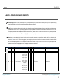
1
DIMinBOX 2Ch 2-Channel Universal Light Dimmer Application program version: [1.0] User manual edition: [1.0]_a www.zennio.com USER MANUAL ZDI-DB2C DIMinBOX 2Ch CONTENTS Contents ................................................................................................................................... 2 1 Introduction ................................................................................................................. 4 1.1 DIMinBOX 2Ch ........................................................................................................... 4 1.2 Load Types ................................................................................................................ 6 1.2.1 1.3 2 Combining Load Types ................................................................................... 6 Installation ................................................................................................................ 8 Configuration ............................................................................................................. 10 2.1 2.2 Main Configuration.................................................................................................. 10 2.1.1 Both Channels .............................................................................................. 11 2.1.2 Channel Cx ................................................................................................... 14 2.1.3 Channel C1+C2 ............................................................................................. 19 2.1.4 Error Notification ......................................................................................... 20 Functions ................................................................................................................. 25 2.2.1 Configuration ............................................................................................... 25 2.2.2 Status Objects .............................................................................................. 26 2.2.3 Custom On/Off ............................................................................................. 28 2.2.4 Simple Timer ................................................................................................ 30 2.2.5 Flashing........................................................................................................ 32 2.2.6 Scenes/Sequences........................................................................................ 34 2.2.7 Lock Channel ................................................................................................ 38 2.2.8 Auto Off ....................................................................................................... 39 2.2.9 Initialization Settings .................................................................................... 40 http://www.zennio.com Technical Support: http://zennioenglish.zendesk.com 2 DIMinBOX 2Ch 2.3 Inputs ...................................................................................................................... 41 2.3.1 Binary Input ................................................................................................. 41 2.3.2 Temperature Probe ...................................................................................... 41 2.3.3 Motion Detector .......................................................................................... 42 2.4 Logic Functions ........................................................................................................ 43 2.5 Manual Control........................................................................................................ 44 2.5.1 Test On Mode .............................................................................................. 44 2.5.2 Test Off Mode .............................................................................................. 45 ANNEX I: Communication Objects ........................................................................................... 46 http://www.zennio.com Technical Support: http://zennioenglish.zendesk.com 3 DIMinBOX 2Ch 1 INTRODUCTION 1.1 DIMinBOX 2Ch DIMinBOX 2Ch is the universal, two-channel, multi-function KNX light dimmer from Zennio. With a maximum per-channel power of 310 W at 230 VAC for resistive (R), inductive (L) and capacitive (C) loads, and of 120 W for dimmable LED / CFL loads (or, respectively, 160 W and 65 W at 110 VAC), it features a wide variety of functions, which make it a versatile and robust device. The most outstanding are: Compatibility with resistive (R), inductive (L), capacitive (C), LED* and lowconsumption CFL* loads. (*) Only dimmable LED / CFL lamps are supported. Automatic load type detection for conventional lamps (C / F / L), Customisable dimming pattern for LED and CFL loads, Customisable dimming times. Individual or joint control of the two output channels, Additional functions: timed actions, scenes, custom on/off controls, automatic switch-off, sequences, economy mode, channel lock… Manual operation and supervision of the loads through the on-board pushbuttons. 10 customisable, multi-operation logic functions. 2 multi-purpose inputs, configurable as: Temperature probes, Binary inputs (i.e., pushbuttons, switches, sensors), Motion detectors. http://www.zennio.com Technical Support: http://zennioenglish.zendesk.com 4 DIMinBOX 2Ch Data storage and load switch-off on bus power losses. Automatic error management (overloads, short-circuits, open circuits, overheating, anomalous network frequencies, power supply failures and wrong load type selection). LED indicators to show error situations. http://www.zennio.com Technical Support: http://zennioenglish.zendesk.com 5 DIMinBOX 2Ch 1.2 LOAD TYPES DIMinBOX 2Ch supports the following load types: R L C CFL LED Figure 1 Load Types Conventional lamps: Resistive (R), Inductive (L), Capacitive (C), Dimmable low-consumption Compact Fluorescent Lamps (CFL). Dimmable Light Emitting Diode (LED) lamps. 1.2.1 COMBINING LOAD TYPES In some cases it is possible to combine different load types in the same channel (i.e. it may be possible to control loads of different types together) as long as the following restrictions are satisfied: Inductive (L) and resistive (R) loads can be combined if the resistive load is less than 50% of the total load. Capacitive (C) and resistive (R) loads can be combined if the resistive load is less than 50% of the total load. Capacitive (C) and inductive (L) loads cannot be combined. CFL and LED loads cannot be combined. CFL and conventional (R / L / C) loads cannot be combined. LED and conventional (R / L / C) loads cannot be combined. http://www.zennio.com Technical Support: http://zennioenglish.zendesk.com 6 DIMinBOX 2Ch It is advisable not to combine different CFL (or LED) loads together in the same channel, as the response may differ depending on the model or maker. Figure 2. Combining Load Types. To get further information, please refer to the corresponding Datasheet, bundled with the original package of the device and also available at www.zennio.com. . http://www.zennio.com Technical Support: http://zennioenglish.zendesk.com 7 DIMinBOX 2Ch 1.3 INSTALLATION DIMinBOX 2Ch connects to the KNX bus through the on-board KNX connector. Once the device is provided with power from the KNX bus, both the individual address and the associated application program can be downloaded. 5 1. Neutral and Phase Lines. 6 7 2. KNX Bus Connection. 3. Prog./Test LED. 4. Prog./Test Pushbutton. 5. Analogue/Digital Inputs. 4 3 6. Output LED Indicator. 7. Manual Control Pushbutton. 8. Output Channels. 2 8 1 Figure 3 DIMinBOX 2Ch - Element Diagram. The main elements of the device are described next: Test/Prog. Pushbutton (4): a short press on this button sets the device into the programming mode, making the associated LED (3) light in red. Note: if this button is held while plugging the device into the KNX bus, the device will enter into safe mode. In such case, the LED will blink in red every 0.5 seconds. Output Channels (8): slots for the connection of the output lines (loads). Neutral and Phase Lines (1): slots for the connection of the neutral and phase lines. Analogue/Digital Inputs (5): input ports for the connection of the stripped cables of external elements such as switches, motion detectors, temperature probes, etc. http://www.zennio.com Technical Support: http://zennioenglish.zendesk.com 8 DIMinBOX 2Ch To get detailed information about the technical features of the device, as well as on the installation and security procedures, please refer to the corresponding Datasheet, bundled with the original package of the device and also available at www.zennio.com. http://www.zennio.com Technical Support: http://zennioenglish.zendesk.com 9 DIMinBOX 2Ch 2 CONFIGURATION 2.1 MAIN CONFIGURATION The main configuration of DIMinBOX 2Ch requires setting some general parameters as well as some more channel-specific options. Once the basics have been defined, it is also possible to enable and customise some additional functions for each channel. The next sections of this manual will describe all the process, as well as the options and concepts involved. ETS PARAMETERISATION After importing the corresponding database in ETS and adding the device into the topology of the desired project, the configuration process begins by right-clicking into the device and selecting Edit parameters. The tab tree on the left shows the Main Configuration tab in the first place. This entry itself comprises by default three subsections that let the integrator set, respectively, the basic parameters for both channels (C1 and C2). Configuring a joint behaviour of the two channels is also possible, as explained later. http://www.zennio.com Technical Support: http://zennioenglish.zendesk.com 10 DIMinBOX 2Ch 2.1.1 BOTH CHANNELS The basic configuration that is common for both channels consists in setting the following: The frecuency of the power network (50 Hertz or 60 Hertz). The length of the dimming course for the two Smooth Dimming functions, which make it possible to increase or decrease the light level of the loads progressively (in contrast to At Once). This length is defined as the time for an entire regulation, from a level of 0% (no light) to a level of 100% (full light). Note: there are several ways of regulating the light level. Later it will be necessary to set which of them should be done at once and which smoothly. Whether to control the two channels independently or jointly (see sections 2.1.2 and 0). The manual control type, in the case that operating the channels through the on-board pushbuttons is necessary for testing or for other purposes. Whether to send error notifications or not to the bus. Enabling or disabling the Inputs module. Enabling or disabling the Logic Functions module. http://www.zennio.com Technical Support: http://zennioenglish.zendesk.com 11 DIMinBOX 2Ch ETS PARAMETERISATION Figure 4 Main Configuration - Both Channels. The Both Channels screen contains the following parameters: Frequency: “50” or “60” Hz. Smooth Dimming Times: 5 to 50 tenths of a second, 1 to 120 seconds or 1 to 4 minutes. The longer the time, the smoother the light regulation. Independent Channel Control: while set to “Yes”, two specific tabs (“Channel C1” and “Channel C2”) will remain available under “Main Configuration” in the tree on the left, as well as two more to configure their respective additional functions (“Channel C1 Functions” and “Channel C2 Functions”). However, if set to “No”, they will be replaced with the equivalent joint tabs (“Channel C1+C2” and “Channel C1+C2 Functions”). All of them will be described later. http://www.zennio.com Technical Support: http://zennioenglish.zendesk.com 12 DIMinBOX 2Ch Manual Control: the options are “Disabled”, “Test Mode Off + Test Mode On”, “Only with Test Mode Off” and “Only with Test Mode On”. Please see section 2.5 for details. Error Notifications: enables or disables the “Error Notifications” tab (within “Main Configuration”), which contains specific parameters for the case DIMinBOX 2Ch is required to report error events to the KNX bus. Please see section 0 for details. Inputs: enables or disables the “Inputs” tab, which contains specific parameters for the case of connecting external accessories to DIMinBOX 2Ch. Please see section 2.3 for details. Logic Functions: enables or disables the “Logic Functions” tab, which contains specific parameters for the case the Logic Functions module is required. Please see section 2.4 for details http://www.zennio.com Technical Support: http://zennioenglish.zendesk.com 13 DIMinBOX 2Ch 2.1.2 CHANNEL Cx The specific configuration for each channel (in case an independent channel control has been configured; see section 2.1.1) consists in setting the following: The load type, which may be RCL (conventional loads), CFL or LED. Different dimming patterns are applied for each case. Please see section 1.2 for details. In the case of a conventional load (RCL), the integrator will have the option to manually set the type (R, C or L) or to let DIMinBOX 2Ch perform an automatic detection. Note: if the integrator opts for setting the conventional type (R, C or L) manually, DIMinBOX 2Ch will be able to notify the KNX installation about the connection of the wrong (conventional) load type. See section 2.1.4. In the case of a CFL or a LED load, the integrator will have the option to select the dimming pattern (among three options) that best fits the load being regulated. It is also possible to select the dimming mode, that is, whether to regulate the load on the trailing edges of the wave or on the leading edges. Some testing with these options is advisable in order to obtain the best results for the specific lamp being regulated. The type of response (immediate or smooth, with two smooth speeds available for configuration at the integrator’s disposal) of the different light controls: precise dimming (i.e., orders to set a specific light level, expressed in terms of percentage), relative dimming (i.e., orders to increase or decrease the current light level by a certain percentage) and switch-on / switch-off. The load switch-on method, being possible to configure that the loads always recover their previous light level (the one they had before being switched off; this is referred to as “memory function”) or the maximum level. Whether to activate the economical mode (only for RCL loads), which consists in proportionally reducing the light level (and thus the energy consumption) by applying a certain coefficient (50% to 100%). Note that this is an internal feature, as the KNX bus will still be reported the theoretical light levels and not the actual, reduced levels. However, the dimming times are not http://www.zennio.com Technical Support: http://zennioenglish.zendesk.com 14 DIMinBOX 2Ch changed, so if, for example the light level has been reduced to 50%, the time it takes to go from 0% to 100% will be half the parameterized. Note: the above coefficient alters (shortens) the actual dimming times. The maximum dimming value (only for CFL and LED loads), which is a value between 50% and 100% that permits a proportional reduction (similarly as the above economical mode) in order to prevent very high dimming levels, which on certain CFL / LED loads can lead to insufficient energy for the dimmer itself, which may cause flickering or false open-circuit error notifications. It is highly recommended to set a value not greater than 80%. The lowest light level permitted (0% to 50%), as certain loads may show flickering or behave improperly in particularly low levels. When DIMinBOX 2Ch receives a request to dim the load to a value greater than 0% but lower than the parameterised limit, it will apply the level parameterised as minimum. ETS PARAMETERISATION Figure 5 Channel Cx. The Channel Cx screen (with “x” being “1” or “2”) contains the following parameters: http://www.zennio.com Technical Support: http://zennioenglish.zendesk.com 15 DIMinBOX 2Ch Load Type: sets the type of the load that will be connected to the output channel. The options are “RCL” (conventional lamps), “CFL” or “LED”. The following two parameters show up in case of selecting “RCL”: Load Selection Mode: “Manual” or “Automatic”. And, in case of selecting “Manual”: Type: “Resistive (R)”, “Capacitive (C/C+R)” or “Inductive (L/L+R)”. On the other hand, the following two parameters show up in case of selecting “CFL” or “LED”: Dimming Pattern: “Lineal”, “Curve 1” or “Curve 2”. Dimming Mode: “Trailing Edge” or “Leading Edge”. Important: please configure these options with caution in order to obtain the best results. Refer to section 1.2 for details. Dimming Speed: sets the type of response (immediate or progressive; see section 2.1.1) for the different control orders. Precise Dimming: “At Once”, “Smooth 1” or “Smooth 2”. Relative Dimming: “At Once”, “Smooth 1” or “Smooth 2” On/Off: “At Once”, “Smooth 1” or “Smooth 2” Memory Function: sets the desired response for the switch-on orders: “Maximum” (maximum light level) or “Previous” (previous light level; that is, a “memory” switch-on). Economical Mode (only available for conventional RCL loads): enables (“Yes”) or disables (“No”) an internal reduction to the light level (and therefore to the energy consumption) by a certain coefficient. Maximum Dimming Value: 50% to 100%. The lower the maximum dimming value, the greater the consumption reduction. http://www.zennio.com Technical Support: http://zennioenglish.zendesk.com 16 DIMinBOX 2Ch Maximum Dimming Value (only available for CFL and LED loads): sets the maximum permitted light level (from 50% to 100%), thus permitting an internal reduction to prevent situations of insufficient energy for the dimmer itself. Values greater than 80% are not recommended. Enable Minimum: “Yes” or “No”. And, in case of selecting “Yes”: Maximum Dimming Value: 0% to 50%. On the other hand, the following communication objects will be available: [Cx] On/Off: one-bit object for the reception of switch orders from the bus. One “1” will switch the light on, while one “0” will switch it off. The dimming speed will be “At Once”, “Smooth 1” or “Smooth 2” according to the parameters, as explained above. [Cx] Dimming: four-bit object for the reception of dimming orders from the bus. The value of the object will be interpreted as the desired step (brighter or darker), according to the KNX standard. The values “0” and “8” interrupt the current regulation: Value Response 0x0 (0) Stop light dimming 0x1 (1) Decrease the light level by 100% 0x2 (2) Decrease the light level by 50% 0x3 (3) Decrease the light level by 25% 0x4 (4) Decrease the light level by 12% 0x5 (5) Decrease the light level by 6% 0x6 (6) Decrease the light level by 3% 0x7 (7) Decrease the light level by 1% 0x8 (8) Stop light dimming 0x9 (9) Increase the light level by 100% 0xA (10) Increase the light level by 50% 0xB (11) Increase the light level by 25% 0xC (12) Increase the light level by 12% 0xD (13) Increase the light level by 6% 0xE (14) Increase the light level by 3% 0xF (15) Increase the light level by 1% Table 1 Responses to the 4-bit Dimming Orders. http://www.zennio.com Technical Support: http://zennioenglish.zendesk.com 17 DIMinBOX 2Ch The dimming speed will be “At Once”, “Smooth 1” or “Smooth 2” depending on the parameterisation, as explained above. [Cx] Precise Dimming: 1-byte object for the reception of the desired light level (in terms of percentage) from the bus. Once again, the dimming speed will be “At Once”, “Smooth 1” or “Smooth 2” depending on the parameterisation, as explained above. Dimming Speed 1: one-byte object that permits decreasing the course time of the “Smooth 1” regulations (see section 0). Being “T” the parameterised length, any value written to this object will be interpreted as how much this T should be decreased. In other words, writing “25%” to this object will speed up the “Smooth 1” progressive regulations by a 25%, making the light regulation last for 75% of the parameterised time. See Table 2. Value Effective Dimming Length (T = parameterised time) 0% T 25% ¾T 33% ⅔T 50% ½T 75% ¼T 100% 0 Table 2 Dimming Speed object. Dimming Speed 2: analogous to the above object, but for “Smooth 2”. http://www.zennio.com Technical Support: http://zennioenglish.zendesk.com 18 DIMinBOX 2Ch 2.1.3 CHANNEL C1+C2 The specific configuration for the two channels (in case a joint channel control has been configured; see section 2.1.1) is entirely analogous to the separated configuration of each channel, although in this case both channels will react together and similarly. Please refer to section 2.1.2 for details. http://www.zennio.com Technical Support: http://zennioenglish.zendesk.com 19 DIMinBOX 2Ch 2.1.4 ERROR NOTIFICATION 2.1.4.1 BUS NOTIFICATIONS Although DIMinBOX 2Ch permanently watches for error events and reacts to them to prevent the loads and the device itself, it can also notify the KNX bus about the occurrence of errors, if such option is set in parameters. The error situations DIMinBOX 2Ch can report are: short-circuits, overvoltage, overheat, anomalous network frequency, power supply failure, open circuit in the load connection and wrong load type selection (in case of having parameterised a RCL load and having manually set the type to resistive, capacitive or inductive instead of letting DIMinBOX 2Ch automatically detect it). 2.1.4.2 LED NOTIFICATIONS In addition to the above, DIMinBOX 2Ch always informs about errors by means of the on-board LED indicators. In case of concurrence of multiple errors, DIMinBOX 2Ch will only notify about the one with a higher priority – other errors with a lower priority (on whatever channel) will not be notified by the LEDs until the former is over. Table 3 shows the error priority and codes. Priority Error Notification 1 Short Circuit The two LEDs of the channel blink alternatively. 2 Overvoltage One of the two LEDs of each channel remains on and the other one blinks every 0.5 seconds. 3 Overheat All the four LEDs remain on. 4 Power Supply Failure Two LEDs (one per channel) blink together every one second. 5 Anomalous Frequency All the four LEDs blink in sequence every 0.5 seconds. 6 Open Circuit The two LEDs of the channel blink together every 1 second. 7 Wrong Load Type One of the two LEDs of the channel remains on and the other one blinks rapidly. Table 3 Error Notification through the on-board LEDs. http://www.zennio.com Technical Support: http://zennioenglish.zendesk.com 20 DIMinBOX 2Ch 2.1.4.3 REACTION TO ERRORS For safety reasons and with independence of the bus notifications, DIMinBOX 2Ch always takes an action when an error is detected. As explained in the next lines, the particular action depends, in practice, on the error that takes place. Note that when this action implies disconnecting the load (i.e., opening the output relay), DIMinBOX will obviously no longer be aware of short-circuit, overvoltage, wrong load type or open-circuit situations, although other errors will still be monitored. In the case of multiple errors happening at the same time, DIMinBOX 2Ch will focus on the error with a higher priority (see Table 3), which is supposed to trigger a more restrictive response action. Short Circuit: when a short circuit takes place, DIMinBOX 2Ch disconnects the load and waits until a new dimming command is received. When that happens, it will simply try to dim the load and will repeat the process if a new short circuit is detected. In case of more than three short circuits in less than two minutes time (without resetting the device), DIMinBOX 2Ch will remain locked for three minutes and ignore any dimming order addressed to that channel. The lock status will be notified to the KNX bus (if configured in parameters), and also by a blue intermittence of the Prog./Test LED. Overvoltage: when an overvoltage situation takes place, DIMinBOX 2Ch disconnects the load and waits until a new dimming command is received. When that happens, it will simply try to dim the load and will repeat the process if a new overvoltage is detected. In case of more than three overvoltages in less than two minutes time (without resetting the device), DIMinBOX 2Ch will remain locked for three minutes and ignore any dimming order addressed to that channel. The lock status will be notified to the KNX bus (if configured in parameters), and also by turning on (in blue colour) the Prog./Test LED. Overheat: When the internal temperature of DIMinBOX 2Ch results to be between http://www.zennio.com Technical Support: http://zennioenglish.zendesk.com 21 DIMinBOX 2Ch 73ºC and 75ºC, the device will lower the light level of the channels to 20%, ignoring later orders to increase the level. Once the temperature is lower than 73ºC, the device will resume the normal behaviour, although the light level will remain as is until a new dimming order is received. When the internal temperature results to be over 75ºC, the device will completely disconnect both channels and switch the loads off. All orders to increase the light level will be ignored. When the temperature falls below 73ºC, the device will resume the normal behaviour, although the light level will remain as is until a new order is received. In addition to the above, DIMinBOX 2Ch is equipped with a resettable fuse, which provides extra protection to the circuitry. Under situations of abnormally high temperature that cannot be solved by disconnecting the loads, this fuse will blow out, thus interrupting all communications and turning DIMinBOX 2Ch completely off. Power Supply Failure: when DIMinBOX 2Ch detects a drop of the power supply, it disconnects both channels and waits until it recovers. Whether the channels should remain off after the power recovery or recover their previous light levels can be parameterised (see section 2.2.9). Anomalous Frequency: when DIMinBOX 2Ch detects an abnormal frequency in the power network, it will react analogously as for the Power Supply Failure. During the anomalous frequency error, the device will still be able to detect to drops of the power supply. Open Circuit: when an open-circuit situation takes place, DIMinBOX 2Ch switches off the loads and starts ignoring any orders to dim the loads. However, in this case it does not actually disconnect the loads (i.e., it applies a light level of 0% but does not open the output relays), which makes it possible to automatically detect the end of the open circuit. When that happens, the loads will recover their previous state, or switch on or stay off (depending on the parameterisation; see section 2.2.9). Wrong Load Type: when DIMinBOX 2Ch detects that the (conventional) load parameterised does not correspond to the load connected to the device, it will disconnect the output channel and wait until a new dimming order is received. http://www.zennio.com Technical Support: http://zennioenglish.zendesk.com 22 DIMinBOX 2Ch When that happens, it will simply try to dim the load and will repeat the process if the load type is still wrong. ETS PARAMETERISATION If “Error notifications” has been enabled in the Both Channels tab (see section 0), an additional entry will be shown in the tab tree on the left. Figure 6 Error Notification. This screen contains one checkbox per error situation (including “Wrong Load Type Selection”, in case of parameterising a conventional load). Marking any of them will add a specific one-bit communication object to the project topology (or two, if the error is channel-dependent but a two-channel control has been configured). The specific error objects are: [Cx] Open Circuit, Power Supply Fault, [Cx] Short Circuit, Overheating, [Cx] Overvoltage, Anomalous Frequency. [Cx] Wrong Load Type Parameterization. http://www.zennio.com Technical Support: http://zennioenglish.zendesk.com 23 DIMinBOX 2Ch These objects are sent to the bus with the value “1” whenever the error they refer to is observed to take place. Once the undesired situation is over, they are sent with the value “0”. Note that, as already explained, if several errors take place at the same time, the response action to the error with the highest priority may mask the other errors, which may therefore not be reported until the former is solved. There is also a secondary object related to some of the error situations: [Cx] Lock due to overvoltages: [Cx] Lock due to short circuits When DIMinBOX 2Ch gets automatically locked after detecting one of these errors multiple times in a brief period, the lock object corresponding to that error will be sent with value “1”. Once the lock state is over, it will be sent with value “0”. Back to the parameters, one more is shown in addition to the above checkboxes: Clear Error Notifications after Bus Voltage Recovery or ETS Download: sets whether the previous state of the enabled error objects should be cleared during the start-up of the device (i.e., whether they should be sent with the value “0” to the KNX bus). This does not mean that DIMinBOX 2Ch will ignore any errors still taking place after the device start-up (in such case, the corresponding object will be sent with the value “1” after being sent with the value “0”), but may be useful to force all error states to zero in the beginning, to update other devices in the KNX installation. http://www.zennio.com Technical Support: http://zennioenglish.zendesk.com 24 DIMinBOX 2Ch 2.2 FUNCTIONS 2.2.1 CONFIGURATION The options described so far are related to the basics and to the light dimming function itself. However, DIMinBOX 2Ch offers some more additional functions, which are disabled in parameters by default. The next subsections describe each of them: status objects, custom On/Off controls, simple timer, flashing, scenes and sequences, channel lock by object, automatic switch-off and initialisation settings. ETS PARAMETERISATION Figure 7 Functions. The Configuration tab of the channel functions is available by default in the tab tree on the left. It consists of a set of checkboxes for all the available functions. Marking any of them will bring a new entry to the tab tree for the parameterisation of that particular function (with the exception of “Enable Lock By Object”, which has no parameters involved). One drop-down box is also provided to select the desired initialisation of the device (“Default” or “Custom”). The next subsections describe each of these functions. http://www.zennio.com Technical Support: http://zennioenglish.zendesk.com 25 DIMinBOX 2Ch 2.2.2 STATUS OBJECTS This function allows implementing, for that particular channel, a one-bit on/off status object and a one-byte (percentage) status object that will report the channel state at any time, thus informing other devices in the KNX installation, if required. These objects are disabled by default. Regarding the one-bit object, it is possible to specify what the value “1” should mean, as it is possible to send it to the bus as long as the light level is higher than 0% or only when it reaches 100%. ETS PARAMETERISATION Figure 8 Status Objects. This Status Objects specific screen contains the following parameters: Send On/Off Status: enables the "[Cx] On/Off (Status)" 1-bit communication object, which reports the on/off state of the output channel when it changes. If enabled, the following parameter also shows up: Send On/Off=1 when: sets when the value "1" will be sent through object "[Cx] On/Off (Status)" to the bus, being the following options possible: Lighting level is not equal to 0%: when the brightness level gets to a value different from 0%, the object "[Cx] On/Off (status)” will send the value “1”. The value "0" will be only sent when the level reaches 0%. Lighting level is equal to 100%: the "[Cx] On/Off (Status)" object will only send the value "1" when the brightness level gets to 100%. The value "0" will be sent in any other case (luminosity not equal to 100%). http://www.zennio.com Technical Support: http://zennioenglish.zendesk.com 26 DIMinBOX 2Ch The On/Off status object is always sent back to the bus after the reception of an On/Off order through the analogous control object. Send Lighting Level Status (%): enables the "[Cx] Lighting Level (Status)" one-byte communication object, which reports –whenever it changes– the status of the light level applied to the output channel in terms of percentage, with an accuracy of ±1%. If enabled, the following parameter also shows up: Min. Time Between Consecutive Sendings: sets every how much time the status object should be sent to the bus during progressive (smooth) dimming. The available range is 1 to 120 seconds or 1 to 4 minutes. The default value is 3 seconds. http://www.zennio.com Technical Support: http://zennioenglish.zendesk.com 27 DIMinBOX 2Ch 2.2.3 CUSTOM ON/OFF This function brings the chance to enable up to two additional On/Off controls for the output channel, and therefore up to two new communication objects to switch the load on or off. These additional controls allow customising the light level of the output for the “on” and the “off” states and whether the commutation should be performed at once or smoothly. The custom On/Off function is particularly useful when the dimmer is required to set a specific brightness level for each room (children bedrooms, hospitals rooms, etc.), other than the maximum light level of the normal On/Off control. In such cases, both functions (Normal and Custom On/Off) can coexist and be used depending on the situation. ETS PARAMETERISATION Once enabled, the Custom On/Off specific screen offers up to two additional On/Off controls for the channel. Figure 9 Custom On/Off. Both can be independently configured through the following parameters: http://www.zennio.com Technical Support: http://zennioenglish.zendesk.com 28 DIMinBOX 2Ch Lighting Level at On: sets the desired light percentage (0% - 100%) to be applied to the channel when the value "1" is received through the "[Cx] Custom On/Off Y" 1-bit communication object (being “Y” equal to 1 or 2). On Type: sets the desired dimming type for the custom switch-on of the channel: At once, Smooth 1 or Smooth 2. Lighting Level at Off: sets the desired light percentage (0% - 100%) to be applied to the corresponding channel when the value "0" is received through the "[Cx] Custom On/Off Y" 1-bit communication object. Off Type: sets the desired dimming type for the custom switch-off of the channel: At once, Smooth 1 or Smooth 2. http://www.zennio.com Technical Support: http://zennioenglish.zendesk.com 29 DIMinBOX 2Ch 2.2.4 SIMPLE TIMER This function allows performing (on the reception of the value “1” through the simple timer object) a switch-on of the load connected to the channel of DIMinBOX 2Ch and a later, automatic (timed) switch-off, being also possible to add delays and to parameterise the time length, the luminosity level and the dimming type. The timed switch-off can also be triggered on demand before the time count ends, by writing the value “0” to the simple timer object. This function may be useful in motion-dependent light control situations, or when the load needs to be switched on and then switched off automatically after a certain time. ETS PARAMETERISATION Once enabled, the following parameters can be configured from the Simple Timer specific tab: Figure 10 Simple Timer. Lighting Level at On: sets the desired light percentage (10% - 100%) to be applied when the timed switch-on is triggered ([Cx] Simple Timer = 1). http://www.zennio.com Technical Support: http://zennioenglish.zendesk.com 30 DIMinBOX 2Ch On Delay: sets the time DIMinBOX 2Ch will wait since the reception of the timed switch-on order and the actual switch-on of the load. The allowed values are: 0 to 3600 s, 0 to 1000 min, 0 to 100h. If no delay is needed, this field should remain at zero. Off Delay: analogous to the previous parameter, but for the timed switch-off orders ([Cx] Simple Timer = 0). On Duration: sets the time the load will stay on before automatically switching off. Allowed values are: 0 – 3600 s, 0 – 1000 min, 0 – 100h. The value “0” in this field means that the load should remain on until a contrary order is received. On/Off Type: sets the dimming type to be applied during the timed switch-on and switch-off of the channel: At once, Smooth 1 or Smooth 2. Enable Retriggering: Disabled: successive arrivals of the Timer On order will not reset the timer. Enabled + Multiply: if the output has already been switched on and the On Duration time is counting, the count will be restarted whenever another “1” is received through the “[Cx] Simple Timer” communication object. Enabled + No Multiply: if the output has already been switched on and the On Duration time is counting, then the actual duration will be “n” times the parameterised time, being “n” the number of times the value “1” is received through the “[Cx] Simple Timer” communication object. The above parameter does not affect the On and Off Delays: If the On (or Off) delay count is running, the timer will NOT be reset even if a new “1” (or a new “0”) is received through the “[Cx] Simple Timer” object. During the simple timing, receiving any other order to regulate the load will interrupt the time count and make DIMinBOX 2Ch execute the new request. http://www.zennio.com Technical Support: http://zennioenglish.zendesk.com 31 DIMinBOX 2Ch 2.2.5 FLASHING This function allows running ON-OFF sequences with customisable lengths (and light levels) for the “ON” and the “OFF” states. It is also possible to set the number of repetitions (up to 255, or otherwise endless), as well as the light level of the output after the last repetition (or when an order to interrupt the flashing is received). The flashing sequence starts when DIMinBOX receives a "1" through the flashing object and stops once it has executed all the configured repetitions (unless an endless sequence has been parameterised). It is possible to interrupt the flashing sequence at any time by sending one “0” to the flashing object. Sending any other control order (e.g., ON/OFF, scenes, etc.) will also interrupt it. Also, it is possible to send the device the order to re-start the flashing sequence during the execution. ETS PARAMETERISATION Once the function has been enabled, the following parameters can be configured from the Flashing specific screen: Figure 11 Flashing. Lighting Level at On: sets the desired light percentage (10% - 100%) to be applied to the load during the “on” stages. http://www.zennio.com Technical Support: http://zennioenglish.zendesk.com 32 DIMinBOX 2Ch On Duration: sets the length of the “on” stages. The available values are 1 to 3600 seconds, 1 to 1000 minutes, 1 to 24 hours (2 seconds by default). Off Duration: analogous to the above parameter, but for the “off” stages. Number of repetitions: number of times the On/Off cycle will repeat during the sequence (from 0 to 255). For endless flashing, please enter “0”; in such case the sequence will repeat until an order to interrupt it (or any other dimming order: On/Off, scenes, etc.) is received. Note: the sequence is triggered by writing the value “1” to object “[Cx] Flashing”,andinterruptedbywritingthevalue“0”tothesameobject. Final Lighting Level: sets the desired light percentage (10% - 100%) after the last repetition or after the reception of the value “0” through “[Cx] Flashing”. http://www.zennio.com Technical Support: http://zennioenglish.zendesk.com 33 DIMinBOX 2Ch 2.2.6 SCENES/SEQUENCES This function allows defining up to ten scenes per channel, which consist in a specific light ambient or dimming sequence than can be triggered by sending the corresponding scene number to the device. An one-bit object is also provided to (re)start the last scene execution, and to stop it. ETS PARAMETERISATION Figure 12 Scenes/Sequences. Once this function has been enabled, each of the ten scenes/sequences can be individually configured from the “Scenes/Sequences” specific screen. One checkbox is shown for each of them. Marking one of these checkboxes brings a new entry to the tab tree, from which it is necessary to configure some fields. Figure 13 Scene. http://www.zennio.com Technical Support: http://zennioenglish.zendesk.com 34 DIMinBOX 2Ch Figure 14 Sequence. These fields are: Scene/Sequence number: sets the scene/sequence identifying number (from 1 to 64). The reception of this number (subtracting 1, according to the KNX standard) through the “[Cx] Scenes/Sequences” object will make the controller perform the corresponding actions. Scene/Sequence type: selects the desired type of response: Scene: Lighting Level. The scene will consist in setting a certain light level (specified in “Lighting Level”) when the "[Cx] Scenes/Sequences" object is received with the proper scene number. “Dimming type” allows setting whether to apply the new level At Once, or progressively (Smooth 1 or Smooth 2). http://www.zennio.com Technical Support: http://zennioenglish.zendesk.com 35 DIMinBOX 2Ch Custom sequence. The response will consist in a customisable sequence of up to five steps/actions, defined through the following parameters: Cyclic: “Yes” will define a cyclic sequence (after the last step, the sequence will start over), while “No” will define a non-cyclic sequence. Next Scene/Sequence: this parameter offers the possibility of triggering –after the last step of the sequence– another sequence. Lighting Level Status Sending: if set to “Send continuously”, the light level will be sent to the KNX bus through “[Cx] Lighting Level (Status)” during smooth dimming (provided that the option to send the status objects has been activated; see section 2.2.2). If set to “Send when sequence ends”, the level will be sent to the bus once the last step of the sequence finishes, even if the sending of the status is enabled or not. In both cases, however, the Status Objects function should have been enabled (see section 2.2.2). For every step (action), the following parameters are required: Lighting Level: sets the desired luminosity for the step (0% to 100%). Duration: sets the time length of the step (i.e., the action time). The available values are 1 – 3600 seconds, 1 – 1000 minutes, and 1 – 24 hours (2 seconds by default). Note: the time space defined here refers to the entire step action, including (if applicable) the smooth dimming time. In case the dimming is too slow and the step action time too short, only a partial light transition will take place. Dimming type: sets the dimming type for the transition between the steps: At once, Smooth 1 or Smooth 2. An object named “[Cx] Start/Stop Sequence” is provided in case a sequence needs to be interrupted (value “0”) or re-started (value “1”). If the value “1” is received while no sequence was being run, the last sequence will be triggered again (or the first one parameterised, if no sequences have been executed before). Note that this object only applies to sequences, not to static scenes. http://www.zennio.com Technical Support: http://zennioenglish.zendesk.com 36 DIMinBOX 2Ch Besides running a scene it is be also possible to save it: if the device receives an order to save the scene (values 128-191 through “[Cx] Scenes/Sequences”), the current luminosity level of the load (and the dimming speed) will be saved, but only if the value corresponds to any of the parameterised scenes (if not, the order will be ignored). http://www.zennio.com Technical Support: http://zennioenglish.zendesk.com 37 DIMinBOX 2Ch 2.2.7 LOCK CHANNEL This function permits locking the channel by sending a "1" through a specific one-bit communication object. From that moment, any action being executed by the channel will stop and the load will maintain the brightness value it currently has. Dimming orders during the lock state will be ignored, while objects common to both channels not implying changes in their light levels will still respond. DIMinBOX 2Ch will unlock the channel when the value "0" arrives through the lock object. The channel will still maintain the same luminosity level: any request received during the lock state will not be run by the channel after the unlock event. After a power failure, the channel will maintain the lock state and the light level: the Initialization Settings (see section 2.2.9) will not apply in this case. Note that the Auto Off (section 2.2.8) function will also be available during the lock. ETS PARAMETERISATION This function has no parameters. Enabling it in the Configuration screen of the channel simply adds an object (“[Cx] Lock”) to the project topology. When this object receives the value “1” the channel will become locked, while the value “0” will resume the normal behaviour. http://www.zennio.com Technical Support: http://zennioenglish.zendesk.com 38 DIMinBOX 2Ch 2.2.8 AUTO OFF If the Auto Off function is enabled, the load controlled by the channel will automatically turn off after a certain time with a light level lower than a parameterisable limit. The Auto Off function counts the time elapsed after the output falls below a certain threshold light level. If this count exceeds the parameterised timeout, DIMinBOX 2Ch will turn the load off. The count will stop if an order to increase back the light level over that limit is received. ETS PARAMETERISATION Figure 15. Auto Off. The only parameters contained by the Auto Off specific screen are: Lighting Level (Threshold): sets the desired light level (5% to 50%) that will trigger the time count. Time: sets the time that should elapse before turning the channel off. The available values are 10 to 3600 seconds, 1 to 1000 minutes and 1 to 24 hours. http://www.zennio.com Technical Support: http://zennioenglish.zendesk.com 39 DIMinBOX 2Ch 2.2.9 INITIALIZATION SETTINGS This function is provided to let the integrator specify the desired load state after DIMinBOX 2Ch recovers from a KNX bus failure or a power supply failure. In case the integrator feels comfortable with the default initialisation settings (load off after an ETS download, and previous light level after a bus or power supply recovery), it will not be necessary to configure this function. ETS PARAMETERISATION Figure 16 Initialization Settings. If parameter “Initialization Settings” (see section 2.2.1) is set to “Custom” (otherwise, DIMinBOX 2Ch will implement the already-described default load initialisation), a specific entry (“Initialisation Settings”) will be added to the tab tree. From this new screen, it is possible to set the “Initial Status” of the load (both after a bus recovery or a power supply recovery) to either “Off”, “On” or “Previous”. If the above is set to “On”, then an additional parameter will show up (“Lighting Level”) to set the desired light level, in terms of percentage. http://www.zennio.com Technical Support: http://zennioenglish.zendesk.com 40 DIMinBOX 2Ch 2.3 INPUTS DIMinBOX 2Ch incorporates two analogue/digital inputs, each configurable as a: Binary Input, for the connection of a pushbutton or a switch/sensor. Temperature Probe, to connect a temperature sensor (model ZN1ACNTC68 S/E/F from Zennio). Motion Detector, to connect a motion detector (model ZN1IO-DETEC-P from Zennio). Important: older models of the Zennio motion detector (e.g., ZN1IO-DETEC and ZN1IO-DETEC-N) will not work properly with DIMinBOX 2Ch. ETS PARAMETERISATION When Inputs has been activated in the General parameters screen, the following droplists will be available for the selection of the specific functions required. Figure 17. Inputs - Configuration All inputs are disabled by default. Depending on the function selected for each input, additional tabs will be included in the menu on the left. 2.3.1 BINARY INPUT Please refer to the specific user manual “Binary Inputs in DIMinBOX 2Ch”. 2.3.2 TEMPERATURE PROBE Please refer to the specific user manual “Temperature Probe in DIMinBOX 2Ch”. http://www.zennio.com Technical Support: http://zennioenglish.zendesk.com 41 DIMinBOX 2Ch 2.3.3 MOTION DETECTOR It is possible to connect motion detectors (models ZN1IO-DETEC-P and ZN1IODETEC-X from Zennio) to the input ports of DIMinBOX 2Ch. This brings the device with the possibility of monitoring motion and presence in the room, as well as the light level. Depending on the detection, different response actions can be parameterised. Please refer to the specific user manual “Motion Detector in DIMinBOX 2Ch” (available at the Zennio homepage, www.zennio.com) for detailed information about the functionality and the configuration of the related parameters. On the other hand, please keep in mind that motion detectors with references ZN1IODETEC and ZN1IO-DETEC-N may report inaccurate measurements if connected to DIMinBOX 2Ch. Moreover, when connected to DIMinBOX 2Ch, the rear micro-switch of models ZN1IODETEC-P and ZN1IO-DETEC-X should be set to “3.3 V” (and not to “5 V”). Please refer to the motion detector specific user manual for details. Note: the ZN1IO-DETEC-P motion detector is compatible with a variety of Zennio devices. However, depending on the device it is actually being connected to, the functionality may differ slightly. Therefore, please refer specifically to the aforementioned user manual “Zennio Motion Detector for DIMinBOX 2Ch”. http://www.zennio.com Technical Support: http://zennioenglish.zendesk.com 42 DIMinBOX 2Ch 2.4 LOGIC FUNCTIONS This module makes it possible to perform numeric and binary operations to incoming values received from the KNX bus, and to send the results through other communication objects specifically enabled for this purpose. DIMinBOX 2Ch can implement up to ten different and independent functions, each of them entirely customisable and consisting in up to five consecutive operations each. The execution of each function can depend on a configurable condition, which will be evaluated every time the function is triggered through specific, parameterisable communication objects. The result after executing the operations of the function can also be evaluated according to certain conditions and afterwards sent (or not) to the KNX bus, which can be done every time the function is executed, periodically or only when the result differs from the last one. Please refer to the specific user manual “Logic Functions module for DIMinBOX 2Ch” (available at the Zennio homepage, www.zennio.com) for detailed information about the functionality and the configuration of the related parameter. http://www.zennio.com Technical Support: http://zennioenglish.zendesk.com 43 DIMinBOX 2Ch 2.5 MANUAL CONTROL The two output channels of DIMinBOX 2Ch can be manually operated and verified by means of the on-board pushbuttons (two pushbuttons per channel), located on the top side of the device. Two alternate approaches are provided for this manual control: Test On Mode, intended for testing the installation and the loads while setting up the device. Test Off Mode, intended for any other purposes during normal, long-term operation of the device. ETS lets configuring which of the two modes (if not both) should be accessible. Moreover, a specific object can also be enabled in parameters in order to lock/unlock the manual control in runtime (to prevent undesired use, for example). The Test Off Mode is active any time (unless disabled in parameters), which means that the on-board pushbuttons will work according to this mode by default. On the other hand, switching to the Test On Mode (unless disabled in parameters) is done by holding the Prog/Test button for at least three seconds. This will turn the LED yellow. Once the button is released, the LED will become green (which means the Test On Mode is now active). Pressing the button again will turn the LED off, which will mean the Test Off Mode has become the active mode again In case of having parameterised a joint control of both channels, only the pushbuttons of channel A will have effect (on both channels, in this case). Note: both manual control modes come enabled from factory. 2.5.1 TEST ON MODE Under this mode, the output channels will be controllable only by means of the manual control itself. Any orders received from the KXN bus will be ignored, and the status objects will not be sent to the bus either. http://www.zennio.com Technical Support: http://zennioenglish.zendesk.com 44 DIMinBOX 2Ch The error notification, lock and timed functions will remain inoperative as well. On the other hand, the Economical mode and the Minimum Light Level will still apply, Note that the Test On Mode will not be accessible while one of the channels has been deactivated for safety reasons (i.e., after the detection of an error; see section 2.1.4.3). Regarding the loads themselves, their reaction to the short and long presses will be as follows: Short press: the load will switch on or off, depending on the button. Long press: depending on the button, the load will keep progressively increasing or decreasing the light level until the button is released. The speed of this regulation will be the one that had been parameterised in ETS for the relative dimming. 2.5.2 TEST OFF MODE Operating the manual control under this mode will be entirely analogous as receiving orders from the KNX bus. In fact, the device will still respond to any requests from the bus, and will send the status objects when corresponding. Under the Test Off Mode, the loads react to the short and long presses the same way they would in the Test On Mode: Short press: the load will switch on or off, depending on the button. Long press: depending on the button, the load will keep progressively increasing or decreasing the light level until the button is released. The speed of this regulation will be the one that had been parameterised in ETS for the relative dimming. http://www.zennio.com Technical Support: http://zennioenglish.zendesk.com 45 DIMinBOX 2Ch ANNEX I: COMMUNICATION OBJECTS “Functionalrange” shows the values that, with independence of any other values permitted by the bus according to the object size, may be of any use or have a particular meaning because of the specifications or restrictions from both the KNX standard or the application program itself. “1st boot” shows the cases where an object is assigned a certain value by the application program after a device download or a full reset. In case the value of such assignment can be parameterised, √ is shown in column “P”. Objects showing a hyphen (-) are not assigned a particular value and therefore can be assumed to be initialised with the value “0”, or with the corresponding updated value in case they depend on an external element (sensors, etc.). Moreover, if the object is sent ( or is there an option to send it) to the bus (write or read requests) after a download or a device reset from ETS, the marks (W) or (R) will be shown, respectively for transmissions or read requests. “Reboot” shows the cases where an object is assigned a certain value by the application program after a bus power failure. In case the value of such assignment can be parameterised, √ is shown in column “P”. Objects showing a hyphen (-) are not assigned a particular value and therefore can be assumed to maintain their previous value after the failure, or with the corresponding updated value in case they depend on external elements. Moreover, if the object is sent (or is there an option to send it) to the bus (write or read requests) after a bus failure, the marks (W) or (R) will be shown, respectively for transmissions or read requests. Number 1 2 3 Size I/O Flags Data type (DPT) Functional Range 1st Boot P Reboot P 1 Bit I C--W- DPT_Switch 0/1 - - [C1] On/Off 0=Off; 1=On 1 Bit I C--W- DPT_Switch 0/1 - - [C1+C2] On/Off 0=Off; 1=On 1 Bit I C--W- DPT_Switch 0/1 - - [C2] On/Off 0=Off; 1=On DPT_Control_Dimming 0x0 (Stop) 0x1 (Dec. by 100%) 0x2 (Dec. by 50%) 0x3 (Dec. by 25%) 0x4 (Dec. by 12%) 0x5 (Dec. by 6%) 0x6 (Dec. by 3%) 0x7 (Dec. by 1%) 0x8 (Stop) 0x9 (Inc. by 100%) 0xA (Inc. by 50%) 0xB (Inc. by 25%) 0xC (Inc. by 12%) 0xD (Inc. by 6%) 0xE (Inc. by 3%) - - [C1] Dimming 4 bits dimmer ctrl 4 Bit I http://www.zennio.com C--W- Name Function Technical Support: http://zennioenglish.zendesk.com 46 DIMinBOX 2Ch 0xF (Inc. by 1%) 4 Bit I C--W- DPT_Control_Dimming 0x0 (Stop) 0x1 (Dec. by 100%) … 0x8 (Stop) 0x9 (Inc. by 100%) … 0xF (Inc. by 1%) - - [C1+C2] Dimming 4 bits dimmer ctrl - - [C2] Dimming 4 bits dimmer ctrl 4 Bit I C--W- DPT_Control_Dimming 0x0 (Stop) 0x1 (Dec. by 100%) … 0x8 (Stop) 0x9 (Inc. by 100%) … 0xF (Inc. by 1%) 1 Byte I C--W- DPT_Scaling 0% - 100% - - [C1] Precise Dimming 1 byte dimmer ctrl 1 Byte I C--W- DPT_Scaling 0% - 100% - - [C1+C2] Precise Dimming 1 byte dimmer ctrl 6 1 Byte I C--W- DPT_Scaling 0% - 100% - - [C2] Precise Dimming 1 byte dimmer ctrl 7 C-RW 1 Byte I/O - DPT_Scaling 0% - 100% - - Dimming Speed 1 0%=Min. Speed; 100%=Max. Speed 8 C-RW 1 Byte I/O - DPT_Scaling 0% - 100% - - Dimming Speed 2 0%=Min. Speed; 100%=Max. Speed 4 5 1 Bit O CTR-- DPT_Alarm 0/1 -W -W [C1] Open Circuit 0=No error; 1=Error 1 Bit O CTR-- DPT_Alarm 0/1 -W -W [C1+C2] Open Circuit 0=No error; 1=Error 10 1 Bit O CTR-- DPT_Alarm 0/1 -W -W [C2] Open Circuit 0=No error; 1=Error 11 1 Bit O CTR-- DPT_Alarm 0/1 -W -W Power Supply Fault 0=No error; 1=Error 1 Bit O CTR-- DPT_Alarm 0/1 -W -W [C1] Short Circuit 0=No error; 1=Error 1 Bit O CTR-- DPT_Alarm 0/1 -W -W [C1+C2] Short Circuit 0=No error; 1=Error 1 Bit O CTR-- DPT_Alarm 0/1 -W -W [C2] Short Circuit 0=No error; 1=Error 1 Bit O CTR-- DPT_Alarm 0/1 -W -W [C1] Lock due to short circuits 0=Unlocked; 1=Locked 1 Bit O CTR-- DPT_Alarm 0/1 -W -W [C1+C2] Lock due to short circuits 0=Unlocked; 1=Locked 15 1 Bit O CTR-- DPT_Alarm 0/1 -W -W [C2] Lock due to short circuits 0=Unlocked; 1=Locked 16 1 Bit O CTR-- DPT_Alarm 0/1 -W -W Overheating 0=No error; 1=Error 1 Bit O CTR-- DPT_Alarm 0/1 -W -W [C1] Overvoltage 0=No error; 1=Error 1 Bit O CTR-- DPT_Alarm 0/1 -W -W [C1+C2] Overvoltage 0=No error; 1=Error 1 Bit O CTR-- DPT_Alarm 0/1 -W -W [C2] Overvoltage 0=No error; 1=Error 1 Bit O CTR-- DPT_Alarm 0/1 -W -W [C1] Lock due to overvoltages 0=Unlocked; 1=Locked 1 Bit O CTR-- DPT_Alarm 0/1 -W -W [C1+C2] Lock due to overvoltages 0=Unlocked; 1=Locked 20 1 Bit O CTR-- DPT_Alarm 0/1 -W -W [C2] Lock due to overvoltages 0=Unlocked; 1=Locked 21 1 Bit O CTR-- DPT_Alarm 0/1 -W -W Anomalous Frequency 0=No error; 1=Error 1 Bit O CTR-- DPT_Alarm 0/1 -W -W [C1] Load Type parameterization error 0=No error; 1=Error 1 Bit O CTR-- DPT_Alarm 0/1 -W -W [C1+C2] Load Type parameterization error 0=No error; 1=Error 9 12 13 14 17 18 19 22 http://www.zennio.com Technical Support: http://zennioenglish.zendesk.com 47 DIMinBOX 2Ch 23 24 25 26 27 28 29 30 31 32 33 34 35 36 37 38 39 1 Bit O CTR-- DPT_Alarm 0/1 -W 1 Bit O CTR-- DPT_Switch 0/1 -W √ -W √ [C1] On/Off (Status) 0=Off; 1=On 1 Bit O CTR-- DPT_Switch 0/1 -W √ -W √ [C1+C2] On/Off (Status) 0=Off; 1=On 1 Bit O CTR-- DPT_Switch 0/1 -W √ -W √ [C2] On/Off (Status) 0=Off; 1=On 1 Byte O CTR-- DPT_Scaling 0% - 100% -W √ -W √ [C1] Lighting Level (Status) 0 - 100% 1 Byte O CTR-- DPT_Scaling 0% - 100% -W √ -W √ [C1+C2] Lighting Level (Status) 0 - 100% 1 Byte O CTR-- DPT_Scaling 0% - 100% -W √ -W √ [C2] Lighting Level (Status) 0 - 100% 1 Bit I C--W- DPT_Switch 0/1 - - [C1] Custom On/Off 1 0=Off; 1=On 1 Bit I C--W- DPT_Switch 0/1 - - [C1+C2] Custom On/Off 1 0=Off; 1=On 1 Bit I C--W- DPT_Switch 0/1 - - [C2] Custom On/Off 1 0=Off; 1=On 1 Bit I C--W- DPT_Switch 0/1 - - [C1] Custom On/Off 2 0=Off; 1=On 1 Bit I C--W- DPT_Switch 0/1 - - [C1+C2] Custom On/Off 2 0=Off; 1=On 1 Bit I C--W- DPT_Switch 0/1 - - [C2] Custom On/Off 2 0=Off; 1=On 1 Bit I C--W- DPT_Start 0/1 - - [C1] Simple Timer 0=Deactivate; 1=Activate 1 Bit I C--W- DPT_Start 0/1 - - [C1+C2] Simple Timer 0=Deactivate; 1=Activate 1 Bit I C--W- DPT_Start 0/1 - - [C2] Simple Timer 0=Deactivate; 1=Activate 1 Bit I C--W- DPT_Start 0/1 - - [C1] Flashing 0=Deactivate; 1=Activate 1 Bit I C--W- DPT_Start 0/1 - - [C1+C2] Flashing 0=Deactivate; 1=Activate 1 Bit I C--W- DPT_Start 0/1 - - [C2] Flashing 0=Deactivate; 1=Activate 1 Byte I C--W- DPT_SceneControl 0-63; 128-191 - - [C1] Scenes/Sequences Scene/Sequence value 1 Byte I C--W- DPT_SceneControl 0-63; 128-191 - - [C1+C2] Scenes/Sequences Scene/Sequence value 1 Byte I C--W- DPT_SceneControl 0-63; 128-191 - - [C2] Scenes/Sequences Scene/Sequence value 1 Bit I C--W- DPT_Start 0/1 - - [C1] Start/Stop Sequence 0=Stop; 1=Start 1 Bit I C--W- DPT_Start 0/1 - - [C1+C2] Start/Stop Sequence 0=Stop; 1=Start 1 Bit I C--W- DPT_Start 0/1 - - [C2] Start/Stop Sequence 0=Stop; 1=Start 1 Bit C-RW I/O - DPT_Enable 0/1 - - [C1] Lock 0=Unlock; 1=Lock 1 Bit I/O C-RW - DPT_Enable 0/1 - - [C1+C2] Lock 0=Unlock; 1=Lock 1 Bit I/O C-RW - DPT_Enable 0/1 - - [C2] Lock 0=Unlock; 1=Lock 1 Bit I/O C-RW - DPT_Enable 0/1 - √ - √ Lock manual control 0=Unlock; 1=Lock 1 Bit C-RW I/O - DPT_Enable 0/1 - √ - √ Lock manual control 1=Unlock; 0=Lock 40 41 42 -W [C2] Load Type parameterization error 0=No error; 1=Error 1 Byte I C--W- 20.xxx 0/1/2 - √ - √ [C1] Edge Select (Only for Test Purposes) 0=Automatic; 1=Leading; 2=Trailing 1 Byte I C--W- 20.xxx 0/1/2 - √ - √ 44 1 Byte I C--W- 20.xxx 0/1/2 - √ - √ [C2] Edge Select (Only for Test Purposes) 0=Automatic; 1=Leading; 2=Trailing 45 1 Byte I C--W- Dimming_Pattern_Non- 0/1/2 - √ - √ [C1] Dimming Pattern (Only for Test 43 http://www.zennio.com [C1+C2] Edge Select (Only for Test Purposes) 0=Automatic; 1=Leading; 2=Trailing 0=Linear; 1=Curve 1; 2=Curve 2 Technical Support: http://zennioenglish.zendesk.com 48 DIMinBOX 2Ch standard DPT 1 Byte I Purposes) C--W- Dimming_Pattern_Nonstandard DPT 0/1/2 - 0/1/2 - √ [C1+C2] Dimming Pattern (Only for Test Purposes) - √ - [C2] Dimming Pattern (Only for Test √ Purposes) 0=Linear; 1=Curve 1; 2=Curve 2 46 1 Byte I C--W- Dimming_Pattern_Nonstandard DPT 47,51 2 Byte O CTR-- DPT_Value_Temp -273.00 - 670760.00 - - [Ix] Current Temperature Temperature sensor value 48,52 1 Bit O CTR-- DPT_Alarm 0/1 - - [Ix] Overcooling 0 = No Alarm;1 = Alarm 49,53 1 Bit O CTR-- DPT_Alarm 0/1 - - [Ix] Overheating 0 = No Alarm;1 = Alarm 50,54 1 Bit O CTR-- DPT_Alarm 0/1 - - [Ix] Probe Error 0 = No Alarm;1 = Alarm 55 1 Byte I C--W- DPT_SceneControl 0-63; 128-191 - - [Motion Sensor] Scene Input Scene Value 56 1 Byte CT--- DPT_SceneControl 0-63; 128-191 - - [Motion Sensor] Scene Output Scene Value 57,81 1 Byte O CTR-- DPT_Scaling 0% - 100% - - [Ix] Luminosity 0-100% 58,82 1 Bit O CTR-- DPT_Alarm 0/1 - - [Ix] Open Circuit Error 0 = No Error; 1 = Open Circuit Error 59,83 1 Bit O CTR-- DPT_Alarm 0/1 - - [Ix] Short Circuit Error 0 = No Error; 1 = Short Circuit Error 60,84 1 Byte O CTR-- DPT_Scaling 0% - 100% - - [Ix] Presence State (Scaling) 0-100% - - [Ix] Presence State (HVAC) Auto, Comfort, Standby, Economy, Building Protection √ 0=Linear; 1=Curve 1; 2=Curve 2 1 Byte O CTR-- DPT_HVACMode 1=Comfort 2=Standby 3=Economy 4=Building Protection 1 Bit O CTR-- DPT_Occupancy 0/1 - - [Ix] Presence State (Binary) Binary Value 1 Bit O CTR-- DPT_Trigger 0/1 - - [Ix] Presence: Slave Output 1 = Motion Detected 63,87 1 Bit I C--W- DPT_Trigger 0/1 - - [Ix] Presence Trigger Binary Value to Trigger the Presence Detection 64,88 1 Bit I C--W- DPT_Trigger 0/1 - - [Ix] Presence: Slave Input 0 = Nothing; 1 = Detection from slave device 65,89 1 Bit I C--W- DPT_Trigger 0/1 - - [Ix] External Motion Detection 0 = Nothing; 1 = Motion detected by an external sensor 66,90 1 Byte O CTR-- DPT_Scaling 0% - 100% - - [Ix][C1] Detection State (Scaling) 0-100% CTR-- DPT_HVACMode 1=Comfort 2=Standby 3=Economy 4=Building Protection - - [Ix][C1] Detection State (HVAC) Auto, Comfort, Standby, Economy, Building Protection 61,85 62,86 67,91 1 Byte O 68,92 1 Bit O CTR-- DPT_Switch 0/1 - - [Ix][C1] Detection State (Binary) Binary Value 69,93 1 Bit I C--W- DPT_Switch 0/1 - - [Ix][C1] Channel Lock According to parameters 70,94 1 Bit I C--W- DPT_Switch 0/1 - - [Ix][C1] Force State 0 = No Detection; 1 = Detection 71,95 1 Byte O CTR-- DPT_Scaling 0% - 100% - - [Ix][C2] Detection State (Scaling) 0-100% CTR-- DPT_HVACMode 1=Comfort 2=Standby 3=Economy 4=Building Protection - - [Ix][C2] Detection State (HVAC) Auto, Comfort, Standby, Economy, Building Protection 72,96 1 Byte O 73,97 1 Bit O CTR-- DPT_Switch 0/1 - - [Ix][C2] Detection State (Binary) Binary Value 74,98 1 Bit I C--W- DPT_Switch 0/1 - - [Ix][C2] Channel Lock According to parameters 75,99 1 Bit I C--W- DPT_Switch 0/1 [Ix][C2] Force State 0 = No Detection; 1 = Detection http://www.zennio.com Technical Support: http://zennioenglish.zendesk.com 49 DIMinBOX 2Ch 76,100 1 Byte O CTR-- DPT_Scaling 0% - 100% CTR-- DPT_HVACMode 1=Comfort 2=Standby 3=Economy 4=Building Protection - [Ix][C3] Detection State (Scaling) 0-100% - [Ix][C3] Detection State (HVAC) Auto, Comfort, Standby, Economy, Building Protection 77,101 1 Byte O 78,102 1 Bit O CTR-- DPT_Switch 0/1 - - [Ix][C3] Detection State (Binary) Binary Value 79,103 1 Bit I C--W- DPT_Switch 0/1 - - [Ix][C3] Channel Lock According to parameters 80,104 1 Bit I C--W- DPT_Switch 0/1 - - [Ix][C3] Force State 0 = No Detection; 1 = Detection 105,111 1 Bit I C--W- DPT_Switch 0/1 - - [Ix] Input Lock 1 = Locked; 0 = Unlocked 1 Bit CT--- DPT_Switch 0/1 -W -W [Ix] [Short Press] 0 Sending of 0 1 Bit CT--- DPT_Switch 0/1 -W -W [Ix] [Short Press] 1 Sending of 1 CT-W- DPT_Switch 0/1 -W -W [Ix] [Short Press] 0/1 Switching Switching 0/1 1 Bit CT--- DPT_UpDown 0/1 -W -W [Ix] [Short Press] Move Up Shutter Sending of 0 (Up) 1 Bit CT--- DPT_UpDown 0/1 -W -W [Ix] [Short Press] Move Down Shutter Sending of 1 (Down) 1 Bit CT--- DPT_UpDown 0/1 -W -W [Ix] [Short Press] Move Up/Down Shutter Switching 0/1 (Up/Down) 1 Bit CT--- DPT_Step 0/1 -W -W [Ix] [Short Press] Stop/Step Up Shutter 1 Bit CT--- DPT_Step 0/1 -W -W [Ix] [Short Press] Stop/Step Down Shutter Sending of 1 (Stop/Step down) 1 Bit CT--- DPT_Step 0/1 -W -W [Ix] [Short Press] Stop/Step Shutter (switched) Switching of 0/1 (Stop/Step up/down) DPT_Control_Dimming 0x0 (Stop) 0x1 (Dec. by 100%) … 0x8 (Stop) 0x9 (Inc. by 100%) … 0xF (Inc. by 1%) -W -W [Ix] [Short Press] Brighter Increase Brightness DPT_Control_Dimming 0x0 (Stop) 0x1 (Dec. by 100%) … 0x8 (Stop) 0x9 (Inc. by 100%) … 0xF (Inc. by 1%) -W -W [Ix] [Short Press] Darker Decrease Brightness -W -W [Ix] [Short Press] Brighter/Darker Switch Bright/Dark 1 Bit I 4 Bit CT--- 106,112 4 Bit CT--- Sending of 0 (Stop/Step up) 4 Bit CT--- DPT_Control_Dimming 0x0 (Stop) 0x1 (Dec. by 100%) … 0x8 (Stop) 0x9 (Inc. by 100%) … 0xF (Inc. by 1%) 1 Bit CT--- DPT_Switch 0/1 -W -W [Ix] [Short Press] Dimmer ON Sending of 1 (ON) 1 Bit CT--- DPT_Switch 0/1 -W -W [Ix] [Short Press] Dimmer OFF Sending of 0 (OFF) CT-W- DPT_Switch 0/1 -W -W [Ix] [Short Press] Dimmer ON/OFF Switching 0/1 1 Bit I http://www.zennio.com Technical Support: http://zennioenglish.zendesk.com 50 DIMinBOX 2Ch 1 Byte CT--- DPT_SceneControl 0-63; 128-191 -W -W [Ix] [Short Press] Run Scene Sending of 0 - 63 1 Byte CT--- DPT_SceneControl 0-63; 128-191 -W -W [Ix] [Short Press] Save Scene Sending of 128 - 191 DPT_Switch 0/1 -W -W [Ix] [Switch/Sensor] Edge Sending of 0 or 1 0 - 255 1 Bit 107,113 1 Byte CT--- DPT_Value_1_Ucount 0 - 255 -W -W [Ix] [Short Press] Constant Value (Integer) 1 Byte CT--- DPT_Scaling 0% - 100% -W -W [Ix] [Short Press] Constant Value (Percentage) 0% - 100% 2 Byte CT--- DPT_Value_2_Ucount 0 - 65535 -W -W [Ix] [Short Press] Constant Value (Integer) 0 - 65535 2 Byte CT--- 9.xxx -671088.64 670760.96 -W -W [Ix] [Short Press] Constant Value (float) Float value 0% = Top; 100% = Bottom 1 Byte I C--W- DPT_Scaling 0% - 100% -W -W [Ix] [Short Press] Shutter Status (input) 1 Byte I C--W- DPT_Scaling 0% - 100% -W -W [Ix] [Short Press] Dimming Status (input) 0% - 100% 1 Bit CT--- DPT_Switch 0/1 -W -W [Ix] [Long Press] 0 Sending of 0 1 Bit CT--- DPT_Switch 0/1 -W -W [Ix] [Long Press] 1 Sending of 1 CT-W- DPT_Switch 0/1 -W -W [Ix] [Long Press] 0/1 Switching Switching 0/1 1 Bit CT--- DPT_UpDown 0/1 -W -W [Ix] [Long Press] Move Up Shutter Sending of 0 (Up) 1 Bit CT--- DPT_UpDown 0/1 -W -W [Ix] [Long Press] Move Down Shutter Sending of 1 (Down) 1 Bit CT--- DPT_UpDown 0/1 -W -W [Ix] [Long Press] Move Up/Down Shutter Switching 0/1 (Up/Down) 1 Bit CT--- DPT_Step 0/1 -W -W [Ix] [Long Press] Stop/Step Up Shutter Sending of 0 (Stop/Step up) 1 Bit CT--- DPT_Step 0/1 -W -W [Ix] [Long Press] Stop/Step Down Shutter Sending of 1 (Stop/Step down) 1 Bit CT--- DPT_Step 0/1 -W -W [Ix] [Long Press] Stop/Step Shutter (switched) Switching of 0/1 (Stop/Step up/down) DPT_Control_Dimming 0x0 (Stop) 0x1 (Dec. by 100%) … 0x8 (Stop) 0x9 (Inc. by 100%) … 0xF (Inc. by 1%) -W -W [Ix] [Long Press] Brighter Long Pr. -> Brighter; Release -> Stop DPT_Control_Dimming 0x0 (Stop) 0x1 (Dec. by 100%) … 0x8 (Stop) 0x9 (Inc. by 100%) … 0xF (Inc. by 1%) -W -W [Ix] [Long Press] Darker Long Pr. -> Darker; Release -> Stop DPT_Control_Dimming 0x0 (Stop) 0x1 (Dec. by 100%) … 0x8 (Stop) 0x9 (Inc. by 100%) -W -W [Ix] [Long Press] Brighter/Darker Long Pr. -> Brighter/Darker; Release -> Stop 1 Bit 108,114 CTRW I/O - I 4 Bit 4 Bit 4 Bit http://www.zennio.com CT--- CT--- CT--- Technical Support: http://zennioenglish.zendesk.com 51 DIMinBOX 2Ch … 0xF (Inc. by 1%) 1 Bit CT--- DPT_Switch 0/1 -W -W [Ix] [Long Press] Dimmer ON Sending of 1 (ON) 1 Bit CT--- DPT_Switch 0/1 -W -W [Ix] [Long Press] Dimmer OFF Sending of 0 (OFF) CT-W- DPT_Switch 0/1 -W -W [Ix] [Long Press] Dimmer ON/OFF Switching 0/1 1 Byte CT--- DPT_SceneControl 0-63; 128-191 -W -W [Ix] [Long Press] Run Scene Sending of 0 - 63 1 Byte CT--- DPT_SceneControl 0-63; 128-191 -W -W [Ix] [Long Press] Save Scene Sending of 128 - 191 1 Bit CTR-- DPT_Alarm 0/1 -W -W [Ix] [Switch/Sensor] Alarm: Breakdown or 1 = Alarm; 0 = No Alarm sabotage 2 Byte CT--- 9.xxx -671088.64 670760.96 -W -W [Ix] [Long Press] Constant Value (float) 2 Byte CT--- DPT_Value_2_Ucount 0 - 65535 -W -W [Ix] [Long Press] Constant Value (Integer) 0 - 65535 1 Byte CT--- DPT_Scaling 0% - 100% -W -W [Ix] [Long Press] Constant Value (Percentage) 1 Byte CT--- DPT_Value_1_Ucount 0 - 255 -W -W [Ix] [Long Press] Constant Value (Integer) 0 - 255 1 Bit CT--- DPT_Trigger 0/1 -W -W 1 Bit 109,115 I O Float value 0% - 100% [Ix] [Long Press/Release] Stop Shutter Release -> Stop Shutter 1 Byte I C--W- DPT_Scaling 0% - 100% 50% W -W [Ix] [Long Press] Dimming Status (input) 0% - 100% 1 Byte I C--W- DPT_Scaling 0% - 100% 50% W -W [Ix] [Long Press] Shutter Status (input) 0% = Top; 100% = Bottom 117-148 1 Bit I C--W- DPT_Bool 0/1 - - [LF] (1 bit) Data Entry X Binary Data Entry (0/1) 149-164 1 Byte I C--W- DPT_Value_1_Ucount 0 - 255 - - [LF] (1 byte) Data Entry X 1 byte Data Entry (0-255) 2 Byte I C--W- DPT_Value_2_Ucount 0 - 65535 - - [LF] (2 bytes) Data Entry X 2 bytes Data Entry 165-180 2 Byte I C--W- DPT_Value_2_Count -32768 - 32767 - - [LF] (2 bytes) Data Entry X 2 bytes Data Entry 2 Byte I C--W- DPT_Value_Temp -273.00 - 670760.00 - - [LF] (2 bytes) Data Entry X 2 bytes Data Entry DPT_Value_4_Count -2147483648 2147483647 - - [LF] (4 bytes) DataEntry X 4 bytes Data Entry 110,116 181-188 4 Byte I C--W- 1 Bit O CTR-- DPT_Bool 0/1 - - [LF] Function X - Result (1 bit) Boolean 1 Byte O CTR-- DPT_Value_1_Ucount 0 - 255 - - [LF] Function X - Result (1 byte) Unsigned 2 Byte O CTR-- DPT_Value_2_Ucount 0 - 65535 - - [LF] Function X - Result (2 bytes) Unsigned DPT_Value_4_Count -2147483648 2147483647 - - [LF] Function X - Result (4 bytes) Signed 189-198 4 Byte O CTR-- 1 Byte O CTR-- DPT_Scaling 0% - 100% - - [LF] Function X - Result (1 byte) Percentage 2 Byte O CTR-- DPT_Value_2_Count -32768 - 32767 - - [LF] Function X - Result (2 bytes) Signed 2 Byte O CTR-- DPT_Value_Temp -273.00 - 670760.00 - - [LF] Function X - Result (2 bytes) Float http://www.zennio.com Technical Support: http://zennioenglish.zendesk.com 52 Join and send us your inquiries about Zennio devices: http://zennioenglish.zendesk.com Zennio Avance y Tecnología S.L. C/ Río Jarama, 132. Nave P-8.11 45007 Toledo (Spain). Tel. +34 925 232 002. Fax. +34 925 337 310. www.zennio.com [email protected]