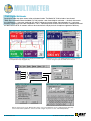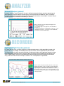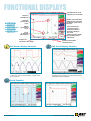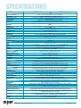
1
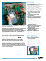
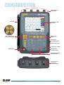
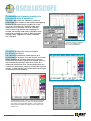
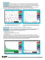
PORTABLE Oscilloscope OX 7100 Series A YE R TY WA 3 RRAN Isolated inputs: 600Vac, 850Vdc to ground and channel-to-channel Five complementary tools in one: Oscilloscope, Multimeter, FFT Analyzer, Harmonic Analyzer and Recorder 12-bit resolution provides deeper accurate zooming Sampling rate 1GS/s in one-shot and 25GS/s in ETS with memory depth of 2500 counts per channel in “oscilloscope” mode Four independent, 4000-count, TRMS, 45kHz, digital multimeters Color LCD with touch screen functions 33 direct command keys and “Windows-like” menus on screen Multi-interface communication connector: RS-232, Centronics and Ethernet with web server Plug-and-play self-identifying and calibrating input probes and accessories Features Field testing is quick and easy thanks to the Model OX 7104-C’s hand strap and the use of Probix Smart Probes, some that have control buttons, with user definable functions, right on the probes themselves. AEMC® Instruments, a world leader in electrical test and measurement instruments, proudly introduces the first self-contained portable four-isolated-channel oscilloscope on the market rated at 600V Cat. III. Featuring five complimentary tools in one – an Oscilloscope, FFT Analyzer, TRMS Multimeter, Harmonic Analyzer and a Recorder. The Model OX 7104-C is a rugged and ergonomic hand-held instrument that is the perfect tool for both laboratory and field testing. Ease of use of the instrument is facilitated through 33 specialized keys for direct access to commonly used functions. Ideal for field use, system the Model OX 7104-C utilizes the patented new of “plug-and-play” accessories, individual isolation of each of the measurement channels and a range of remote management capabilities. The Ethernet link with web server has a number of built-in instruments, including a four-channel TRMS multimeter. The large 320 x 240 full color LCD screen provides detailed graphical and alphanumerical representations of all measurements and also functions as a touch screen. Using the convenient stylus, the various “Windows-like” menus can be opened or pulled down and executed. The stylus can also be used for direct action on graphic elements such as cursors, triggers, zooming, etc. Isolated inputs; 600Vac, 850Vdc to ground and channel-to-channel Five complementary tools in one: Oscilloscope, Multimeter, FFT Analyzer, Harmonic Analyzer and Recorder Sampling rate 1GS/s in one-shot mode and 25GS/s in ETS — memory depth of 2.5k per channel in “oscilloscope” mode Four isolated measurement channels, 600V Cat III with up to eight traces on screen 12-bit resolution provides deeper accurate zooming Real-time FFT analysis standard and calculation functions on the channels Four independent, 4000-count, TRMS, 45kHz, digital multimeters Color LCD touch screen 33 direct command keys and “Windows-like” menus on screen Multi-interface communication connector: RS-232, Centronics and Ethernet with web server Stylus for touch screen menu/function access and manipulating graphic elements on screen Probix smart probes with user definable control buttons Plug-and-play self-identifying and calibrating input probes and accessories NATO approved: OX 7102-C — 6625 14 549 3558 OX 7104-C — 6625 14 549 3559 Applications On-site contractor maintenance — industrial or electronic “Internal” plant maintenance Installations and start-up Industrial process Quality control Research and laboratory — engineers or technicians Field service Windows-like menus can be pulled down and executed with the convenient stylus. 2 www.aemc.com Technical Assistance (800) 343-1391 CONSTRUCTION Isolated inputs for each channel Hand strap Direct access keys to four instrument modes 1/4 VGA (320 x 240) Color LCD Utility program buttons Charging port Test signal terminals Communications port Trigger mode selection ON/OFF button Shockproof dirt resistant overmold Horizontal and vertical trace adjustments Isolated inputs for each channel rated 600V Cat. III Technical Assistance (800) 343-1391 www.aemc.com 3 OSCILLOSCOPE Comprehensive triggering functions to record only what is necessary The AEMC ® Instruments OX 7100 series are the first oscilloscopes in this category to offer sophisticated triggering functions that go beyond primary triggering on a front, or even on a pulse duration. The delay mode allows observation of any event with maximum resolution, even if it occurs long after the actual triggering. For example, the counting mode makes it possible to count events prior to triggering, in order to check the content of digital frames. Triggering can also be associated with a TV signal. Triggering delay in the channel occurs after a delay of 35.2µs with respect to the auxiliary source. This is user programmable. Complete automatic measurements for precise analysis The automatic measurements window displays up to 18 parameters for any signal. For a clear analysis, two markers identify the portion of the signal where the first automatic measurement was made. A specific measurement zone can then be selected by outlining it with manual cursors, for a reliable and more precise result. A direct comparison of two waveforms is performed by checking “variation from reference memory”, in order to display up to 18 parameters of the signal as differences from the reference. Automatic measurement within limits set by the cursors If mathematical functions, scales, or physical units are defined, these measurements allow for them to be directly displayed. This makes a practically infinite number of current and power measurements available with 4-digit resolution, thanks to the 12-bit A to D. 4 www.aemc.com Technical Assistance (800) 343-1391 Math functions In oscilloscope mode, the math functions (1, 2, 3 and 4) can be used on each trace to define a mathematical function and vertical scaling in actual physical unit(s). The real-time on-screen display capability of the mathematical editor presents four calculated trace results, on which all cursor-selected and automatic measurements are available. It is therefore possible to examine waveforms as power, for example (V x I), and make all associated measurements. Many math functions are available, for example +, -, x, /, as well as sine, cosine, exponent, logarithm, square root, etc., giving access to your exact application. When two channels are multiplied, the result can be displayed to scale, with its physical unit (kW, for example shown in math 3), together with the original traces, here the current and the voltage and calculated wattage are shown. Many complex functions can be edited, including the simulation of a trace from its mathematical equation. Therefore the model of an expected result or reference can be stored. All functions created can be stored practically without limit and retrieved for later use. Real-time Fast Fourier Transform (FFT) for frequency analysis The FFT is used to calculate, at 2,500 points, the discrete representation of a signal in the frequency domain from its representation in the time domain. It is a powerful means to effectively diagnose and analyze signal quality: • measurement of the various harmonics and distortion of a signal • analysis of impulse response • the search for a noise source in logical circuits • and much more Several weighting windows are available including Rectangle, Hanning, Hamming and Blackman, along with two representation modes, linear and logarithmic (scale in dB). The two cursors can then be used to make precise measurements of frequency spikes, levels, and attenuations, taking advantage of the 80dB dynamic range allowed by the 12-bit / 1-GS/s conversion. The autoset makes it easier to obtain an optimum spectral representation on which a graphic zoom can be applied in order to analyze all details of the spectrum. FFT with a Hanning window and a logarithmic scale Technical Assistance (800) 343-1391 FFT with a rectangular window and a linear scale www.aemc.com 5 MULTIMETER TRMS Digital Multimeter Pressing the meter key gives access to the multimeter function. The Model OX 7104 includes a four-channel TRMS digital multimeter where the Model OX 7102 includes a two-channel digital multimeter — the basic instruments for all diagnostics — measures amplitude (AC and DC voltage and current, power, thermocouples, etc.), resistance, continuity, capacitance and to test components. The PT 100 configuration can be used to measure a temperature based on 100W resistive RTD. All sensors used can be scaled to their true physical unit for optimum application efficiency. Values for each of the multimeters are displayed simultaneously, both alphanumerically and graphically. Parameters for each of the TRMS multimeters can be selected on screen using the stylus and “Windows-like” menus. With the stylus and on-screen “Windows-like” menus, each of the multimeters can be configured quickly and easily. Set the measurement parameters, vertical scale and configure the probes for each channel independently. 6 www.aemc.com Technical Assistance (800) 343-1391 ANALYZER Harmonic Analyzer (optional) Harmonic analysis is a basic function for all users in the fields of power distribution, electrical engineering and power electronics. With the optional Harmonic Analysis firmware installed, the Model OX 7104-C can display harmonics up to the 31st for signals having fundamental frequencies between 40 and 450Hz. Harmonic analysis can be displayed on all channels simultaneously, in real-time. Harmonic analysis results are displayed in bargraph form. The status zone indicates: • the total RMS voltage of the signal in V, the total harmonic distortion in % • for the selected harmonic or fundamental, the value in % of the fundamental, the phase in ° with respect to the fundamental, the frequency in Hz, the RMS voltage. RECORDER High-Speed Digital Recorder (optional) For users who must track variations of physical or mechanical phenomena, a high-speed digital recorder, with sample rates as fast as 800µs and recording times up to one month, can be incorporated into the instrument. The Recorder offers the ability to monitor thresholds and tolerance windows with triggering of long-term storage of the phenomenon observed and the automatic capture of successive time-stamped faults (510 defaults and up to 127,000 samples). Analysis can be performed on the instrument itself (even mathematical calculations using values from more than one channel) or standard “.TXT” files exported to a spreadsheet. Thanks to the Probix system, the OX 7100 series oscilloscopes manage a wide range of sensors (voltage, current, temperature, 0-10V, 4-20mA, etc.) and displays the signals in their original engineering units (scale and unit). The measurement cursors (the last acquisition and the mobile cursor) can be used with the zoom function to perform a precise analysis of the signals being acquired or already acquired. Technical Assistance (800) 343-1391 www.aemc.com 7 FUNCTIONAL DISPLAYS Instrument menus for all functions plus on-line help Display of selected trace Menus can be opened and graphic elements can be moved using the cursor. Automatic measurement cursor Manual measurement cursor Cursor or automatic measurements Position and movement of time trigger Display Trace parameters, Math Function parameters or Memory, in the color of the trace Value of time based coefficient (s/div) in Oscilloscope mode or Frequency (Hz/div) in FFT mode Context sensitive display area showing current adjustments Position and movement of manual cursors Full Screen Display Function Full Trace Display Function The FULL SCREEN feature provides full screen display of waveforms, without other information or menus, at the push of a button. The FULL TRACE feature activates horizontal splitting of the display screen, allowing you to view waveforms from independent channels separately. Zoom Function 8 www.aemc.com Technical Assistance (800) 343-1391 Specifications Model INTERFACE Screen Specifications Display Mode No. of Traces on Screen Front Panel Control Screen Control Languages VERTICAL Bandwidth Channels Input Impedance Maximum Permanent Input Voltage Vertical Sensibility Accuracy Vertical Zoom Probe Factors HORIZONTAL Time Base Speed Accuracy Horizontal Zoom TRIGGERING Mode Source Type Coupling Sensitivity DIGITAL MEMORY Maximum Sampling Speed Vertical Resolution Memory Capacity per Channel User Memory Other Modes XY Mode OTHER FUNCTIONS Autoset FFT Analyzer and Math Functions Cursors Automatic Measurements MULTIMETER AC, DC, AC + DC voltage Resistance Other Measurements RECORDER (optional) Acquisition Rate Duration of Recording Acquisition Mode Operation HARMONIC ANALYZER (optional) Analysis Span Operation GENERAL SPECIFICATIONS Configurations Memories Ethernet Network Printing (standard) RS-232 or Centronics (options) Communication Power Source Dimensions Weight OX 7102-C OX 7104-C Color 5.7” LCD (115 x 86mm) 320 x 240 — CCFL backlighting Vectors with interpolation — 500 samples on screen Four traces and four references — Split screen and full screen modes (tracing zone 110 x 74) 32 direct shortcuts Touch screen — “Windows-like” menus and graphic commands Five complete languages, menus and on-line help (English, French, German, Spanish, Italian) Two isolated channels 100MHz Four isolated channels 1M½ ± 0.5% approx. 17pF 600V Cat. III — Derating -20dB/decade from 100kHz 16 ranges from 2.5mV to 200V/div ±1.5% x5 maximum 1 / 10 / 100 / 1 000 or scaling to any value — Definition of the measurement unit 35 ranges from 1ns/div to 200s/div ±1.5% x10 maximum Auto, trigger, single, Auto 50% CH1, CH4 CH1, CH2, CH3, CH4 Front, pulse or delay (40ns/20s), count (2/16384) or TV (525 or 625 lines) AC, DC, HFR, LFR, noise reduction — Hold-off adjustable from 40ns to 1s 0.6 div to 1KHz / 1.5 div to 150MHz 25GS/s in ETS - 1GS/s in one-shot (on each channel) 12 bits “TRC” approx. 10kB, “TXT” approx. 20kB 1MB Envelope mode (Factors from 2 to 64) Between two from the four traces — math functions and cursors Complete autoset at less than 3s, with recognition of channels — Frequency > 30Hz FFT, + , - , x , / - Editor of mathematical functions Two or three cursors : V and T simultaneous or Phase Resolution 12-bit, display four digits 18 level or time measurements, phase measurements — Resolution 12-bit, display four digits From 400.0mV to 600VRMS or 800Vdc - Accuracy Vdc 0.5 % R+ 5D — bandwidth 45kHz 80.00 to 32.00M - Precision 0.5 % R+ 25D — Rapid 10-ms continuity test Capacities 5.000nF to 5.000mF/Frequency 45kHz — Diode test 3.3V Sampling interval from 800µs to 18mn approximately From 2s to 31 days Conditional on thresholds or windows — Normal or “510-faults” acquisition Time stamped graphic recording, conversion and units of physical quantities, measurement using cursors and search for events, standard file format usable in spreadsheets (.TXT) Even or odd orders up to 31, or first 16 orders Permanent display: total RMS value and total harmonic distortion — Order selected: % F, phase, freq, VRMS Unlimited — “.CFG” file size approx. 1kB 11 black and white or color drivers : IBM Proprinter, Epson ESC/P, Canon HP PCL, Seiko DPU411, Postscript Image files: “.BMP” 10kB, “.GIF” approx. 5kB (storage in memory transfer by RS-232 or Ethernet) Local via Ethernet 10 MB or RS 232 (option) — Remote via 10 MB Ethernet and web server included “SX-METRO” application software for PC (option) 9.6V/3.8 A/h battery pack — Approx. 4h between charges — Adjustable power-saving switching Multi-voltage 98-254V / 47-63Hz — Fast charge in two hours (oscilloscope off) 10.25 x 7.25 x 2” (261 x 185 x 53mm) 4.2 lbs (1.9kg) with batteries Technical Assistance (800) 343-1391 www.aemc.com 9 SOFTWARE The Ethernet interface and its web server offer new ways of working and communicating, local or remote, with a convenience and effectiveness that will quickly make them necessities. All that is needed for communication is that the other equipment (printer, PC, etc.) has an IP address. Thus, even on the road, you can print results on a network printer, exchange files between the OX 7100 series oscilloscopes and a computer. You can also monitor the instrument remotely from any PC, display the traces in real-time and control it using the instrument panel. Whether locally or at a distance, these transfer and exchange operations are simple and rapid and do not require special software on the computer, thanks to the web server. Real-time display of all active channels by using SX METRO software supplied Snapshot display of multiple waveforms and FFT data using SX METRO software For the first time, these portable oscilloscope tools for industrial and electronic maintenance eliminate the traditional problems of printing, backing up and documenting traces due to the incorporation of internet and LAN interface. In the oscilloscope, multimeter, analyzer and recorder modes, the web server ensures unparalleled effectiveness, very simply, with no need to install software on the local or remote PC. 10 www.aemc.com Technical Assistance (800) 343-1391 PROBIX system Smart Probes & Adapters The PROBIX system is your assurance that using the instrument will not only be rapid but also, more importantly, error-free, which is critical for devices used for troubleshooting. For unfailing compatibility, the connection of BNC connectors or standard test leads is accomplished using the safety adapters provided. An interchangeable plastic ring can be used to match the color of the accessory to the color of its channel. Power is supplied and the sensors are calibrated directly from the oscilloscope. Some accessories have three control buttons accessible on the probe itself. Automatic recognition of sensors and connection accessories: Probix probes and adapters are plug-and-play and are recognized immediately when connected. The instrument not only identifies them, but also configures to their characteristics. Active safety is built in, notably in the form of safety information and recommendations concerning the accessory used. A pop-up screen displays: • • • • • the the the the the maximum input voltage maximum voltage to ground maximum voltage between channels type of sensor being used use of a suitable safety lead Configuration of the channels and management of the sensors: The coefficients, scales and units of the sensors and the channel configurations are managed automatically. The first two control buttons on the probes are used to directly modify the adjustment parameters of the channel to which they are connected or to copy functions from the front panel of the oscilloscope. The third button is specific to the accessory. On voltage probes, for example, it controls the lighting of the measurement area. When the connection is made, all preferred parameters stored in the accessories (assignments of buttons one and two, color) are automatically reactivated. They can be modified using the Probix “pop-up” shown to the right. Technical Assistance (800) 343-1391 www.aemc.com 11 ORDERING INFORMATIONCATALOG NO. Portable Oscilloscope Model OX 7102-C (Two 100MHz, Color) . . . . . . . . . . . . . . . . . . . . . . . . . . . . . . . . . . . . . . . . . . . . . 2124.50 Includes: Oscilloscope; one ProiPRHX1, 1/10 Probes, 250MHz, 600V Cat. III; one PROBIx BNC adapters; one PROBIX 4mm banana plug adapter; one US power adapter (115V, 60Hz); one battery pack, NiMH 19.6V, 3.8Ah; one set-of-two color-coded leads, 1.5m (red/black) with needle probe tips; one crossed Ethernet cable; one RS-232/9-pin D-SUB cable; set of two stylus; aluminum carrying case, three-year product warranty and registration card and user manual on CD-ROM Portable Oscilloscope Model OX 7102-C Kit (Two 100MHz, Color — Kit) . . . . . . . . . . . . . . . . . . . . . . . . . . . . . . . . . . . . . 2124.53 Includes: AEMC® Cat. #2124.50 (above), plus one straight Ethernet cable; SX-METRO data processing and analysis software and one set-of-two grip probes (red/black) Portable Oscilloscope Model OX 7104-C (Four 100MHz, Color). . . . . . . . . . . . . . . . . . . . . . . . . . . . . . . . . . . . . . . . . . . . . 2124.54 Includes: Oscilloscope; two PROBIX PR, 1/10 Probe, 250MHz, 600V Cat. III; two PROBIX BNC adapters; one PROBIX 4mm banana plug adapter; one US power adapter (115V, 60Hz); one battery pack, NiMH 19.6V, 3.8Ah; one set-of-two color-coded leads, 1.5m (red/black) with needle probe tips; one crossed Ethernet cable; one straight Ethernet cable; SX-METRO data processing and analysis software; one RS-232/9-pin D-SUB cable; one set-of-two grip probes (red/black); set of two stylus; aluminum carrying case, three-year product warranty and registration card and user manual on CD-ROM Portable Oscilloscope Model OX 7104-C Power Kit (Four 100MHz, Color — Kit). . . . . . . . . . . . . . . . . . . . . . . . . . . . . . . 2124.63 Includes: AEMC® Cat. #2124.54 (above), plus the OX Power Kit (Cat. #2124.88) which includes two PROBIX PRHX1, 1/10 Probe, 250MHz, 600V Cat. III; two PROBIX 4mm banana plug adapters; three PROBIX current probes, 20mA to 80A, 100kHz; one PROBIX PRHX7, K thermocouple adapter; three set-of-two color-coded 1.5m leads and clips (red/black 4mm straight, 4mm right angle); small classic tool bag Accessories (Optional) SX-METRO/P Software, Data Retrieval Processing. . . . . . . . . . . . . . . . . . . . . . . . . . . . . . . . . . . . . . . . . . . . . . . . . . . . . . . . . 2124.70 Harmonic Analyzer, Firmware — upgrade. . . . . . . . . . . . . . . . . . . . . . . . . . . . . . . . . . . . . . . . . . . . . . . . . . . . . . . . . . . . . . . . 2124.71 Recorder Function, Firmware — upgrade . . . . . . . . . . . . . . . . . . . . . . . . . . . . . . . . . . . . . . . . . . . . . . . . . . . . . . . . . . . . . . . . 2124.72 PROBIX PRHX1, 1/10 Probe, 250MHz, 1000V Cat. II (600V Cat. III). . . . . . . . . . . . . . . . . . . . . . . . . . . . . . . . . . . . . . . . . . . 2124.73 PROBIX PRHX4, BNC adapter . . . . . . . . . . . . . . . . . . . . . . . . . . . . . . . . . . . . . . . . . . . . . . . . . . . . . . . . . . . . . . . . . . . . . . . . 2124.74 PROBIX PRHX5, 50W adapter. . . . . . . . . . . . . . . . . . . . . . . . . . . . . . . . . . . . . . . . . . . . . . . . . . . . . . . . . . . . . . . . . . . . . . . . . 2124.75 PROBIX Banana Plug (4mm) adapter . . . . . . . . . . . . . . . . . . . . . . . . . . . . . . . . . . . . . . . . . . . . . . . . . . . . . . . . . . . . . . . . . . . 2124.76 PROBIX Current Probe, 20mA to 20A peak, 100kHz . . . . . . . . . . . . . . . . . . . . . . . . . . . . . . . . . . . . . . . . . . . . . . . . . . . . . . . 2124.77 PROBIX PRH7, K thermocouple adapter. . . . . . . . . . . . . . . . . . . . . . . . . . . . . . . . . . . . . . . . . . . . . . . . . . . . . . . . . . . . . . . . . 2124.78 Carrying Case, Aluminum with foam cut-outs . . . . . . . . . . . . . . . . . . . . . . . . . . . . . . . . . . . . . . . . . . . . . . . . . . . . . . . . . . . . . 2124.79 Ethernet Cable, straight . . . . . . . . . . . . . . . . . . . . . . . . . . . . . . . . . . . . . . . . . . . . . . . . . . . . . . . . . . . . . . . . . . . . . . . . . . . . . . 2124.80 Ethernet Cable, crossed . . . . . . . . . . . . . . . . . . . . . . . . . . . . . . . . . . . . . . . . . . . . . . . . . . . . . . . . . . . . . . . . . . . . . . . . . . . . . 2124.81 RS-232 Adapter/Centronics . . . . . . . . . . . . . . . . . . . . . . . . . . . . . . . . . . . . . . . . . . . . . . . . . . . . . . . . . . . . . . . . . . . . . . . . . . . 2124.82 RS-232 Cable/9-pin D-SUB cable . . . . . . . . . . . . . . . . . . . . . . . . . . . . . . . . . . . . . . . . . . . . . . . . . . . . . . . . . . . . . . . . . . . . . . 2124.83 Leads, set of two, color-coded (1.5m) (black and red, 4mm straight, 4mm right angle) with color-coded safety alligator clips (black and red). . . . . . . . . . . . . . . . . . . . . . . . . . . . . . . . . . . . . . . . . . . . . . . . . . . . . . . 2124.84 Leads, set of two, color-coded (1.5m) (black and red) with Needle Probe Tips . . . . . . . . . . . . . . . . . . . . . . . . . . . . . . . . . . . 2124.85 Grip Probes, set of two, color-coded (black and red). . . . . . . . . . . . . . . . . . . . . . . . . . . . . . . . . . . . . . . . . . . . . . . . . . . . . . . . 2124.86 OX Power Kit . . . . . . . . . . . . . . . . . . . . . . . . . . . . . . . . . . . . . . . . . . . . . . . . . . . . . . . . . . . . . . . . . . . . . . . . . . . . . . . . . . . . . . 2124.88 Metallic carrying case holds the oscilloscope and all accessories. Call the AEMC® Instruments Technical Assistance Hotline for immediate consultation with an applications engineer: (800) 343-1391 Export Department: (978) 526-7667 • Fax (978) 526-7605 • E-mail: [email protected] Chauvin Arnoux®, Inc. d.b.a AEMC® Instruments • 200 Foxborough Blvd. • Foxborough, MA 02035 USA • (800) 343-1391 • (508) 698-2115 • Fax (508) 698-2118 Visit our website at www.aemc.com Chauvin Arnoux One Source™ 950.BR-SCOPE_0108Rev02 Printed in the USA