1
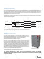
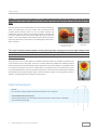
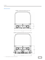
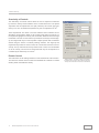
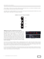
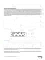
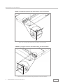
Instrumented Treadmill
User Manual
Version 2.0 2013
www.bertec.com
Contact
For customer support or sales, please contact:
Bertec Corporation
6171 Huntley Road Suite J
Columbus, OH 43229
Phone: (614) 543-8099
Fax: (614) 430-5425
Information: [email protected]
Sales: [email protected]
Support: [email protected]
www.bertec.com
i
Bertec Corporation Instrumented Treadmill Manual
Copyright
Version 2.0
Copyright © 2013 Bertec Corporation. All rights reserved. Information in this document is subject to change without notice.
Companies, names, and data used in examples herein are fictitious unless otherwise noted. No part of this document may
be reproduced or transmitted in any form or by any means, electronic or mechanical, for any purpose, without express written
permission of Bertec Corporation or its licensees.
Dominate Your Field, Bertec, and their logos are trademarks of Bertec Corporation. Other trademarks are the property of their
respective owners.
Printed in the United States of America.
Bertec’s authorized representative in the European Community regarding CE:
Bertec Limited
31 Merchiston Park
Edinburgh EH10 4PW
Scotland, U.K.
Phone: +44 131 229 1634
ii
Bertec Corporation Instrumented Treadmill Manual
Software License
Software License Agreement and Limited Warranty
This License Agreement is between you (“Customer”) and Bertec Corporation, the author of the Bertec Workbook software and governs your use of the program, example results, and documentation (all of
which are referred to herein as the “Software”).
THIS IS A LEGAL AGREEMENT BETWEEN YOU (EITHER AN INDIVIDUAL OR AN ENTITY), THE END USER, AND BERTEC CORPORATION. IF YOU DO NOT AGREE TO THE TERMS OF THIS
AGREEMENT, PLEASE CONTACT BERTEC CORPORATION.
1. Limited Warranty Except with respect to any Bertec Corporation products sold by or manufactured by any entity other than Bertec, its authorized distributors, or suppliers, which are provided “as is”, without warranty of
any kind, Bertec warrants that (a) the Bertec hardware product is free of all defects in workmanship and material for a period of one (1) year from receipt by the end user or date of installation if such
installation is performed by a representative of Bertec; (b) the media that Bertec software is delivered upon are free from defects in workmanship and material and will perform substantially in accordance
with the accompanying written materials for a period of one (1) year; and (c) Bertec support engineers will make commercially reasonable efforts to solve any problem issues as they arise. Some states and
jurisdictions do not allow limitations on duration of an implied warranty, so the above limitation may not apply to you. To the extent allowed by applicable law, implied warranties on both the Bertec hardware
product and the Bertec software product are limited to one (1) year.
2. Grant of License
Bertec grants to you a non-exclusive, non-transferable license, without right to sublicense, distribute or modify, for you and your employees to use the enclosed software and related documentation
(collectively the “Product” or the “Software”) as delivered by Bertec only at one location for the testing and evaluation. If the terms of this license agreement are violated, Bertec immediately terminates said
license and the customer is subject to the liability of any harm done to Bertec Corporation.
3. Title
The product is copyrighted by Bertec. Bertec retains all rights, title, and ownership of the Product and all subsequent full or partial copies and derivatives of the Product, made by you or Bertec, including
translations, compilations, partial copies, modifications, updates and know-how in connection there with, regardless of the form or media in or on which the same may exist. This license is not a sale of the
Product or any copy or derivative. You shall have no right to reproduce any full or partial copies of the Product. You agree not to take any steps, such as reverse assembly or reverse compilation, to derive
a source code equivalent of any software contained in the product. You also agree to destroy licensed data in all forms upon termination of said license or receipt of released program code.
4. Confidentiality
You agree that the product, and other information, technical data, or know-how (including documentation) related to the Product (including the existence of the product and the results of use or testing), shall
be considered Confidential Information of Bertec. You agree to protect the confidentiality of all Confidential Information of Bertec, and not to disclose the Confidential Information to any other party without
the written permission of Bertec. Unauthorized use or disclosure of the Product may cause irreparable harm to Bertec. You agree promptly to report any unauthorized use or disclosure to Bertec.
5. Warranty of Functionality
Bertec hereby represents and warrants that Bertec is the owner of the Product or otherwise has the right to grant to you and your employees the rights set forth in this Agreement. THE PRODUCT IS
PROVIDED “AS IS”. THERE ARE NO WARRANTIES UNDER THIS AGREEMENT, AND BERTEC DISCLAIMS ANY IMPLIED WARRANTY OF MERCHANTABILITY OR FITNESS FOR PARTICULAR
PURPOSE. In the event of any breach or alleged breach of this warranty, you shall promptly notify Bertec and return the Product to Bertec at your expense. Your sole remedy shall be that Bertec shall correct
the Product so that it operates according to the warranty. This warranty shall not apply to the Product if modified by anyone, or if used improperly, or with, on, in an operating environment not approved by
Bertec. To the maximum extent permitted by applicable law, Bertec and its distributors disclaim all other warranties and conditions, either express or implied, including, but not limited to, implied warranties
of merchantability, fitness for particular purpose, title and non-infringement, with regard to the Bertec Product or the provision or failure to provide support services. This limited warranty gives you specific
legal rights. You may have other legal rights not mentioned in this warranty. These rights may vary in each state or jurisdiction.
6. Limitation of Liability
I N
NO EVENT SHALL BERTEC BE LIABLE FOR ANY LOSS OF PROFITS, LOSS OF USE, SPECIAL, INCIDENTAL OR CONSEQUENTIAL DAMAGES PURSUANT TO THIS AGREEMENT. Bertec shall
not be responsible for, and shall not pay, any amount of incidental, consequential or other indirect damages, whether based on lost revenue or otherwise, regardless of whether Bertec was advised of the
possibility of such losses in advance. In no event shall Bertec’s liability hereunder exceed the amount of license fees paid by you, regardless of whether your claim is based on contract, tort, strict liability,
product liability or otherwise. To the maximum extent permitted by applicable law, in no event shall Bertec (including any of Bertec’s subsidiaries or parent companies, suppliers, distributors, retailers, or
manufacturers) be liable for any special, incidental, indirect, or consequential damages whatsoever (including, without limitation, damages for lost business profit, business interruption, loss of business
information, or any other pecuniary loss) arising out of the use of or inability to use the Bertec product or the provision or failure to provide support services, even if Bertec or its affiliates have been advised
of the possibility of such damages. The total liability of Bertec and/or its affiliates for any loss, damage or claim, whether in contract, tort (including active or passive negligence or strict liability) or otherwise,
arising out of, connected with, or resulting from the performance or breach of any purchase order or contract of sale accepted or executed by Bertec and/or its affiliates, or from the design, manufacture,
sale, delivery, resale, inspection, assembly, testing, repair, replacement, operation, maintenance or use of any Bertec product or accessory or from the performance of any service shall not, in any event,
exceed the price allocable to the product or service which gives rise to the claim, loss or damage. Provided further, that the end user assumes all risk associated with the use or misuse of the Bertec
product, accessory or service in contravention of any directions or warnings provided in Bertec instructional literature or given verbally by an authorized Bertec representative, or that should be reasonable
by commercially acceptable standards. The parties (Bertec, Bertec’s affiliates, and the customer or end user) expressly agree that the limitations on incidental, consequential, special or indirect damages set
forth herein are agreed allocations of risk constituting in part the consideration for the sale of any Bertec Product, accessory, or service, and that such limitations shall survive the determination of any court
of competent jurisdiction that any remedy provided herein or available at law fails of its essential purpose. Because some states and jurisdictions do not allow the exclusion or limitation of liability, the above
limitation may not apply to you.
7. Product Maintenance
During the Warranty Period, Bertec shall provide to you any new, corrected or enhanced version of the Product as created by Bertec. Such enhancement shall include all modifications to the Product which
increase the speed, efficiency or ease of use of the Product, or add additional capabilities or functionality to the Product, but shall not include any substantially new or rewritten version of the Product. These
updates will require Internet Access to our website to automatically validate your License Key and provide update support. After expiration of the Warranty Period, you may continue to receive maintenance
support. The charge for such optional maintenance support shall be Bertec’s regular list price for maintenance and support for the Product as published from time to time by Bertec. You will need to notify
Bertec in writing if you desire to receive optional maintenance. If you fail to take optional maintenance and later elect to receive it, Bertec reserves the right to charge you their standard maintenance fees for
the period of the lapse in maintenance. Bertec may elect to discontinue maintenance at any time upon notice to you, and refund of any then unearned maintenance fees.
8. Proprietary Rights Exclusion
Bertec makes no representation or warranty that the Product, or products developed using the Product, do not infringe any proprietary rights of any third parties. You shall assume sole responsibility for any
such infringement.
9. Indemnification
You hereby agree to indemnify, defend and hold Bertec harmless from and against any and all claims, actions, suits, liabilities, judgments, losses, damages, attorneys’ fees and other expenses of every
nature and character by reason of this Agreement or use by you of products utilizing the Product.
10. Export Restrictions
You shall not export, directly or indirectly, any Product or products developed using the Product to any country for which the laws of the United States or the regulations of any U.S. agency requires an export
license or other governmental approval, without first obtaining such license or approval. You shall strictly comply with all such restrictions. You agree to indemnify and hold Bertec harmless against all losses,
damages, penalties, or causes of action resulting from a violation of this Section.
11. Anti-Piracy and License Activation
You must not engage in the distribution of pirated software or hardware. Use of the Product may be limited to the first 14 days after the end user first uses the software, unless the end user activates the
Product, as described in and by the Product. Certain Bertec products may use technological measures for copy protection. In that event, you will not be able to use the Product if you do not fully comply
with the Product Activation Procedures. Product Activation will take place during initial launch of the product, installation on a different system, or replacement of the installed operating system or certain
hardware changes.
12. Governing Law
The validity, performance, construction and interpretation of this Agreement shall be governed by laws of the state of Ohio, United States of America, excluding its conflicts of laws rules, as applied to
agreements entered into in Ohio between Ohio residents.
13. High Risk Activities
The software and/or hardware supplied by Bertec Corporation is not fault-tolerant and is not designed, manufactured or intended for use or resale as on-line control or equipment in hazardous environments
requiring fail-safe performance in which the failure of software and/or hardware could lead directly to death, personal injury, or severe physical or environmental damage (“high risk activity”). Bertec
Corporation and its suppliers specifically disclaim any express or implied warranties of fitness for high risk activities.
14. Customer’s Remedies
Bertec’s and its distributors’ entire liability and the customer’s exclusive remedy shall be, at Bertec’s option, to either repair or replace all Bertec hardware and/or software products that do not meet Bertec’s
Limited Warranty and are returned to Bertec. Cost of delivery of the Bertec product, to and from Bertec, will be the responsibility of Bertec for the first year of the warranty period. Thereafter, all costs
associated with transport of the Bertec product shall be the responsibility of the customer. This Limited Warranty is void if failure of the Bertec hardware and/or software products has resulted from improper
installation by the customer (in contravention of proper installation instructions as detailed in the user’s manual included with the Bertec product), unauthorized modifications, misuse or abuse of the Bertec
product by the customer, and/or failure by the customer to properly maintain the Bertec product. Any replacement Bertec product will be warranted for the remainder of the original warranty period.
Should you have any questions concerning this Agreement, please write to:
Bertec Corporation
6171 Huntley Road, Suite J
Columbus, Ohio 43229
iii
Bertec Corporation Instrumented Treadmill Manual
Table of Contents
01Introduction
02
02
03
03
04
Technical Specifications
System Components
Electronic Control Unit
Optional Equipment
Treadmill Design
05
07
08
Safety Labels
Intended Use
Safety Information and Labeling
09Installation
09
General Considerations and Recommendations
10
Power Requirements
11
Site Preparation
12Dimensions
14Checklist
15
Installation Process
16
Lifting of Treadmill Components
16
Cleaning Instructions
17
Treadmill Start
17
Control Panel
18Settings
20
20
22
23
25
25
iv
Up
Data Acquisition and Load Calculations
Amplifiers and Signal Converters
Auto Zero
Calculating Load Values
Calculation of the Point of Application of Force and Couple
Load Computation Example
Bertec Corporation Instrumented Treadmill Manual
Introduction
Bertec’s instrumented dual belt treadmills have been specifically designed for dynamic analysis of human locomotion. Through the
use of strain gauge technology, innovative design, and quality manufacturing, Bertec’s instrumented treadmills are well suited for
locomotion applications in limited laboratory spaces. Each treadmill consists of a number of strain gauged load transducers and a
built-in digital pre-amplifier for signal conditioning.
Each half of Bertec’s dual belt treadmill incorporates an independent force plate measuring six load components – the three
orthogonal components of the resultant force and the three components of the resultant moment in the same orthogonal coordinate
system. The point of application of the force and the couple acting can be readily calculated from the measured force and moment
components independently for each half of the treadmill.
Bertec treadmills use a state-of-the-art 16-bit digital technology for signal acquisition and conditioning. This technology makes
the use of calibration matrices obsolete, since each treadmill half comes with the calibration matrix digitally stored on it. External
amplifiers available for use with the treadmills provide the user with three signal output alternatives: digital, analog, or dual digital/
analog outputs. The digital signal output can be directly plugged into the standard USB port of a personal computer without the
requirement of an additional PC card for analog-to-digital (A/D) signal conversion. This plug-and-play technology allows a simpler
installation procedure in a minimum amount of time.
The analog signal output can be fed into an A/D board so that data can be collected using conventional techniques. Depending
on the application, signal amplification can be performed for analog output using external amplifiers. External amplifiers are either
fixed or adjustable gain (four and seven adjustable gain models available). These amplifiers enable the user to establish a trade-off
between the measurement range and the resolution of the treadmills.
Bertec’s dual belt treadmills can easily be incorporated with the commercially available motion analysis systems to be used in a
fully equipped locomotion laboratory.
Optional accessories for the treadmill are available as add-on features. These accessories include an incline feature, which can be
used to tilt the treadmill up to 15˚ and a safety harness attachment.
01
Bertec Corporation Instrumented Treadmill Manual
Back to Top
Treadmill Design
Bertec’s dual belt treadmill consists of two 20” treads running side by side. Each tread has a 6-component force plate integrated
into its structure to measure loads exerted on the tread belts. Each tread is driven and controlled separately. The tread belt and
force plate structure are constructed such that the forces generated by the tread belt and the tension from the driving timing belt are
internal forces and do not affect the load measurement. Both halves of the treadmill sit on a rigid steel structure or a split mounting
plate depending on the requested model. The handrails are attached to this structure or directly to the mounting plates.
Locomotion analysis can provide significant information regarding the kinetics and kinematics of human motion. The necessity for
proper foot placement decreases the efficiency of locomotion analysis using conventional, stationary force plates. Use of a dual
belt instrumented treadmill eliminates the need for targeting the force plate to record valid ground reaction data and avoids the
cumbersome process of multiple trials. In addition to increased efficiency, the controllable belt speed allows testing a wide range
of subjects ranging from the elderly population to sprinting athletes.
Bertec treadmills are calibrated and pre-assembled in the factory. Do not attempt to change adjustments or disassemble the
treadmill - damage can occur to the transducer components or electronics. The limited warranty is void if the treadmill or any of the
accessories are disassembled without the authorization of Bertec.
Technical Specifications
Fully Instrumented
Treadmill (FIT)
Mini-FIT for Animal
Application
Quad-FIT for Quadrupedal
Applications
Dimensions (in)
81.1 x 54.6 x 15.3
Max Allowable Load, N (lb)
(per treadmill side)
6,675 (1500)
3,335 (750)
3,335 (750)
Max Load Range, N (lb)
Fx, Fy: 2,225 (500)
Fz: 4,450 (1,000)
Fx, Fy: 1,100 (250)
Fz: 2,225 (500)
Fx, Fy: 1,110 (250)
Fz: 2,225 (500)
Speed Range, km/h (mi/h)
0-24 (0-15)
0-24 (0-15)
0-24 (0-15)
Acceleration, m/s² (ft/s²)
0-25 (0-82)
0-25 (0-82)
0-25 (0-82)
Max Sound Level
90 dB
Number of Belts
2
2
4
Size of Belts
Two independent force
measuring running belts,
approximately 1.75 m (70
in) long and 0.5 m (20 in)
wide per belt.
Two independent force
measuring running belts,
approximately 1 m (40
in) long and 0.3 m (12 in)
wide per belt. *0.15 m (6
in) wide version available.
Four independent force
measuring running belts,
approximately 1 m (40 in) long
and 0.3 m (12 in) wide per belt.
Left side speed is controlled
separately from the right side
speed.
*0.15 m (6 in) wide version
available.
Walking Surface, m (in)
02
1.75 x 1 (approx. 70 x 40)
Bertec Corporation Instrumented Treadmill Manual
1 x 0.6 (approx. 40 x 24)
1 x 0.3 (approx. 40 x 12)
2 x 0.6 (approx. 80 x 24)
Back to Top
Treadmill Design
System Components
Figure 1 below demonstrates individual components of a typical instrumented treadmill. The split belt treadmill (with optional incline
unit) is connected with 4 cables (6 in case of incline module), each 9 m long, to the Electronic Control Unit. One output goes to
an AM6500-TM unit that is used to control the treadmill via USB port of the computer using a standard USB cable. All of the FPA
cables are standard 10 m long Bertec® FPA-10 cables.
All treadmill control is carried out using software on the computer. The Electronic Control Unit does not have any active control
other than an emergency stop button.
FIGURE 1: Instrumented treadmill system layout
FPA cable
Tread 1
Tread 2
Electronic
Control Unit
FPA cable
Signal converter*
AM6500-TM
Signal converter*
USB cable
Output cable**
Computer
Output cable**
3-phase power
* AM6500, AM6501, AM6504, AM6800
** Standard Cable is 1 m long with BNC or Bare Wire output. Should be specified at the time of order.
Electronic Control Unit
The control electronics are housed in a separate cabinet. The cabinet contains an
electronics panel which holds the power electronics, motor drive units, and safety circuitry.
Due to control signal and power restrictions, the maximum distance from the
treadmill motors to the electronics cabinet is roughly 6 m.
Motor power and motor feedback cables exit the bottom of the control cabinet and can
be routed to the treadmill motors either through a conduit or freely on the ground. These
cables should not span any large distances unsupported. The treadmill control cabinet is
connected to a PC running the Bertec Treadmill Control Panel software in the following
manner: A gray cable with a 9-pin d-sub connector exits the control cabinet and is plugged
into an AM6500-TM unit. This AM6500-TM is then connected to the controlling PC via a
USB cable. This PC must be running the Bertec Treadmill Control Pane software in order
to properly control the treadmill belts and/or treadmill incline.
The control cabinet power cord also exits the unit from the bottom.
Treadmill Electronic Control Unit
The electrical network used to supply power to the data acquisition systems and treadmill
electronics rack should be properly grounded. Poor grounding is a common source of signal noise
in electronic systems.
03
Bertec Corporation Instrumented Treadmill Manual
Back to Top
Treadmill Design
Cables can be a hazard for tripping. It is recommended that all cables be routed to prevent tripping.
Alternatively, use a floor cable cover or some other non-permanent means to hold the cables to the
floor.
The main features of the treadmill Electronic Control Unit are the power
switch, the status lights, the door handle, and the Remote E-Stop
Pendant. When the power switch is in the on position (vertical), the
cabinet door cannot be opened, even if the door handle is unlocked and
in the open position. Each control cabinet ships with a key for the door
handle. It is recommended that the cabinet remain locked at all times
and the key be stored in a safe manner. The status lights include Power,
Motor, and Fault.
On/Off Power Switch handle
is in the off position when the
handle is horizontal
Electronic Control Unit
Status Lights
The control cabinet contains power circuitry that operates at dangerous current and voltage levels.
At no time should the electronics be turned on while the cabinet door is open. There are no user
serviceable parts contained in the control cabinet, any work inside the cabinet is to be done by
Bertec Corporation.
The final feature of the control cabinet is the Remote E-Stop Pendant. The pendant is tethered to the
control cabinet via a 25 m long cable. The user is not able to detach the pendant from outside the cabinet
and the treadmill will not be operable if the cable is detached from inside the cabinet. The pendant houses
an emergency stop button as well as an auxiliary button. The E-Stop button can be pressed at any time
to stop the treadmill belts or incline and prevent further belt or incline movement until the button is twisted
and released from its pushed position. When pushed, the button remains in a locked position until it is
rotated in a clockwise direction and allowed to pop back up.
Remote E-Stop Pendant
Optional Equipment
Incline:
Do more tests. Analyze uphill and downhill movements up to 15 degrees.
Overhead Structure and Harness:
Ensures subject safety. Prevents falls and off-track movement. Users can be comfortable
and confident during testing.
04
Bertec Corporation Instrumented Treadmill Manual
Back to Top
Safety Information and Labeling
IMPORTANT SAFETY INSTRUCTIONS
When using the instrumented treadmill, basic precautions should always be followed, including
the following:
To reduce the risk of personal injury, read and understand all the instructions before using this
treadmill.
DANGER - To reduce the risk of electric shock:
1. Always unplug the treadmill from the electrical outlet immediately after using and before
cleaning.
WARNING - To reduce risk of burns, fire, electric shock, or injury to persons:
1. The treadmill should never be left unattended when plugged in. Unplug from outlet when
not in use and before putting on or taking off parts.
2. Close supervision is necessary when the treadmill is used by, on, or near children,
invalids, and disabled persons.
3. Use the treadmill only for its intended use as described in this manual. Do not use
attachments not recommended by the manufacturer.
4. Never operate the treadmill if it has a damaged cord or plug, if it is not working properly,
or if it has been damaged. Contact Bertec Corporation for service examination and repair.
5. Never operate the treadmill with the control cabinet air vents blocked. Keep the air vents
free of lint, hair, etc.
6. Never drop or insert any object into any opening.
7. Do not use outdoors.
8. To disconnect, turn all controls to the off position, then remove the plug from the outlet.
9. Connect this treadmill to a properly grounded outlet only. See Grounding Instructions.
SAVE THESE INSTRUCTIONS
05
Bertec Corporation Instrumented Treadmill Manual
Back to Top
Safety Information and Labeling
GROUNDING INSTRUCTIONS
This product must be grounded. If it should malfunction or break down, grounding provides
least resistance for electric current to reduce the risk of electric shock. This product is equipped
with a cord having an equipment-grounding conductor and a grounding plug. The plug must
be plugged into an appropriate outlet that is properly installed and grounded in accordance
with all local codes and ordinances.
DANGER - Improper connection of the equipment-grounding conductor can result in a risk
of electric shock. Check with a qualified electrician or serviceman if you are in doubt as to
whether the product is properly grounded. Do not modify the plug provided with the product if it will not fit the outlet, have a proper outlet installed by a qualified electrician.
This product is for use on a circuit having a nominal rating more than 200 V and is factory
equipped with a specific electric cord and plug to permit connection to a proper electric circuit.
Make sure that the product is connected to an outlet having the same configuration as the
plug. No adapter should be used with this product. If the product must be reconnected for use
on a different type of electric circuit, the reconnections should be made by qualified service
personnel.
06
Bertec Corporation Instrumented Treadmill Manual
Back to Top
Safety Information and Labeling
Safety Labels
FIGURE 2: Important labels on the Instrumented Treadmill and Electronic Control Unit
This caution label is located on the handrail. Since the treadmill
has moving belts, it is recommended to hold the handrails while
stepping on or off the belts.
This label is placed on the side of the base of the treadmill. All
body limbs should remain clear of this area to avoid injury.
Do not exceed the maximum load capacity recommended by this
label.
This label specifies the operating voltage, current, and frequency
of each treadmill.
Located on the Remote E-stop Pendant, this label informs the
user that the pendant is used to stop the belt immediately.
07
Bertec Corporation Instrumented Treadmill Manual
Back to Top
Safety Information and Labeling
This label on the Electronic Control Unit warns users to not open
the cabinet due to high voltage and electric shock risk.
Each treadmill has four pinch point labels located on the four
corners on top of the treadmill base. These labels indicate areas
where body parts can be pinched or injured.
These labels list the serial numbers for the treadmill and the
Electronic Control Unit.
If labels begin to wear to the point that they are illegible, contact Bertec Corporation for new ones.
Intended Use
Operation of the treadmill outside of the scope of intended use carries with it the risk of injury to the operator and subject and risk
of damage to the treadmill system.
The intended uses are as follows:
1. The treadmill is intended for use in the areas of research and rehab using human subjects wearing typical footwear or no
footwear. The treadmill is not intended to be used with any type of footwear having a metal ground contact component, i.e.
metal sports cleats. The treadmill is not intended for use with wheelchairs.
2. Bertec Corporation is not responsible for verification or validation of customer’s research protocols, application for and
attainment of required IRB’s, or any other conclusions regarding the validity of the research protocol or data generated to
facilitate such research.
3. Normal operating conditions such as those found in a typical clinical or office environment at temperature ranges and limited
fluctuations found in a typical indoor and climate controlled office environment. Customer ensures proper power supply,
grounding, and adherence to local, regional and national building and electrical code standards required to maintain such
environmental standards.
4. Not intended for household use.
08
Bertec Corporation Instrumented Treadmill Manual
Back to Top
Installation
Proper preparation of the installation site will ensure that the performance of the Bertec Instrumented Treadmill is maximized.
The following guidelines are provided so that the treadmill can be properly installed and optimally operated. Note that the actual
conditions and setup at each individual installation site might be different than the ones depicted in this guideline.
Some of the arrangements and constructions mentioned in this guideline might take a long time to make. Therefore, sufficient
time should be spared for planning and site preparation. This guideline describes the steps to be taken by the customer before
installation takes place. Installation and maintenance of the treadmill should be done by authorized personnel only.
General Considerations and Recommendations
The treadmill is designed for indoor use only. It should not be subjected to excessive moisture or dust. Its place of installation
should be maintained at a temperature between 55˚F and 90˚F.
To obtain a high quality measurement from Bertec treadmills, they should be installed in a way that is suitable for the type of
measurement to be performed. First of all, the floor and structure underneath should be prepared to be as rigid as possible in order
to minimize any vibrations.
Depending on the laboratory setup, Bertec Instrumented Treadmills can be installed directly on to the floor or into a specially
constructed pit to have the walking surfaces of the treads flush with the rest of the floor. The pit might be constructed either by
digging into the existing floor or by raising the floor around the treadmill. In case of a pit installation, the void pit space around the
treadmill should be filled with suspended flooring for safety reasons. For accurate measurements the suspended flooring should not
touch the treadmill. At least ½” gap is recommended between the treadmill and the surrounding floor. It is strongly recommended
that the false flooring around the treadmill is custom fitted after the installation is completed. The individual units of the false flooring
should be easily removable so that periodic maintenance service can be performed. Although Bertec does not provide pit and false
flooring design and installation services, we encourage the customers to consult with us about their final designs.
Installation of the treadmill is done in two steps:
>> Step 1: Installation of the mounting plate(s). The epoxy for the mounting plates needs to cure overnight to set properly.
>> Step 2: Installation of the individual treads, handrails and assembly of the electronics cabinet followed by testing and user
training to run the system.
Bertec Instrumented Treadmills are mounted on special precision-machined aluminum mounting plates. The mounting plates
are attached to the floor (or to the bottom surface of the pit) using a special two-part epoxy. A bare concrete underlying surface
is ideal for mounting plate attachment. A floor covered with tiles, linoleum etc. might cause a decrease in the performance of the
treadmill. The concrete surface should be properly leveled so that it is flat within ±3 mm (±⅛”) tolerance. The concrete surface
should be cleaned with a vacuum cleaner and should be free of any dust and particles. It is the customer’s responsibility to bring
the installation site up to the specs.
Dual Belt Instrumented Treadmills are designed such that the right and left treads are mechanically isolated from each other to
prevent transmission of impact forces between treads. However, structurally weak floors might cause unwanted vibrations that
affect treadmill operation. Floor vibration, especially in the upper stories of the buildings, is a common occurrence. Therefore, it is
strongly recommended that the treadmill be installed in the building at the entrance level with no basement underneath, or at the
basement level. Otherwise, it is the customer’s responsibility to make sure that floor vibration is not going to affect operation of the
treadmill.
09
Bertec Corporation Instrumented Treadmill Manual
Back to Top
Installation
Proper power should be available at the installation site so that the treadmill can be tested after installation.
Power Requirements
Bertec Instrumented Treadmills need standard industrial 3-phase power supply to operate.
Three components of the treadmill system must be supplied with power: the treadmill control cabinet and both amplifiers. The
cabinet will connect to its power supply using a straight bladed plug specified by Bertec. The cabinet should be within easy reach
of the power source. Each amplifier takes power from a standard wall outlet, 120 V in North America for example. The treadmill is
operated using one control input. This is a B-type USB connector located on the AM6500-TM unit.
The voltage and current requirements change depending in which country the customer is located. The customer is responsible for
supplying the correct power with the proper wall receptacle for the treadmill. The power plugs and main power supply necessary
to run the standard speed dual treadmill is given in the following table:
FIGURE 3: Instrumented treadmill power requirements
Location
Voltage/Phase (V)
Current Phase (A)
Frequency
Plug on Treadmill
North America
208±10%
40 A
60 Hz
15-50P*
Japan
200±10%
40 A
50/60 Hz
15-50P*
Europe
400±10%
20 A
50 Hz
532P6W**
Australia
400±10%
20 A
50 Hz
56PA532
*NEMA Standard
**IEC-60309 Standard
For power requirements in other locations, please consult Bertec Corporation.
10
Bertec Corporation Instrumented Treadmill Manual
Back to Top
Installation
Site Preparation
In case of a floor installation, at least a 60 cm (2 ft) area on all sides of the treadmill should be clear and unobstructed for a proper
installation.
In case of a pit installation, pit length and width should be at least 120 cm (4 ft) larger [60 cm (2 ft) on each side] than the dimensions
of the treadmill (L x W). In case of suspended flooring these minimum dimensions apply to the units of the raised floor that needs
to be removable (to decide on the exact locations of the support columns for suspended flooring consult Bertec Corporation for
detailed dimensional drawings). For a flush tread surface, 6 mm (¼”) should be added to the height of the treadmill (parameter H
in Figures 7 and 8). As indicated previously, the floor (bottom of the pit) should be flat within ±⅛". The following table summarizes
the required dimensions for the treadmill pit:
FIGURE 4: Required pit dimensions for instrumented treadmill
Parameter
Dimensions
Minimum pit length, cm (in)
L + 120 (L + 48)
Minimum pit width, cm (in)
W + 120 (W + 48)
Pit depth, mm (in)
H + 6 (H + 0.25)
Tolerance: ±3 mm (±⅛")
Note that for systems with the optional incline module, extra space is needed between the treads and adjacent false flooring to
allow the extra rotational motion of the incline unit.
Incorporating a wire conduit into the pit construction is recommended for safety reasons to avoid tripping over the cables. The
recommended diameter is 10 cm (4”) for straight conduits and 13 cm (5”) for conduits with bends and turns. Since the standard
length of the cables running between the treadmill and the electronics control unit is 9 m, the cable conduit lengths should be sized
accordingly allowing for any amount of extra slack cable needed. A guide wire should be available in the conduit to run the cables.
Alternatively, the cables can be run under the false flooring. In case of floor installations, over-the-floor cable covers can be used
as a safety precaution.
The pit should be cleaned thoroughly after construction and should be free of any debris and dust. Cleaning with a vacuum cleaner
is strongly recommended, as dust particles will prevent the mounting plate epoxy to attach to the floor properly.
11
Bertec Corporation Instrumented Treadmill Manual
Back to Top
Installation
Dimensions
FIGURE 5: Instrumented treadmill (front view)
FIGURE 6: Instrumented treadmill with incline (front view)
12
Bertec Corporation Instrumented Treadmill Manual
Back to Top
Installation
FIGURE 7: Instrumented treadmill (side view)
FIGURE 8: Instrumented treadmill with incline (side view)
13
Bertec Corporation Instrumented Treadmill Manual
Back to Top
Installation
Checklist
Use the following checklist to verify that your laboratory is ready for the Bertec Instrumented Treadmill installation. Skip the items
in the list that do not apply to your installation setup.
14
□□
Mechanical characteristics of the floor are such that vibrations will not affect force measurements or they can be
digitally low-pass filtered.
□□
The installation floor is concrete and level within the specs (see Site Preparation).
□□
Measurements of the pit comply with the dimensions given in this guideline. In case of floor installation there is enough
clear area around the treadmill for a comfortable installation (see Site Preparation).
□□
A conduit or an over-the-surface cable cover is provided to route the cables safely to the electronic control unit (see
Site Preparation).
□□
The false flooring around the treadmill is easily removable for periodic maintenance.
□□
There is proper clearance between the false flooring and the treadmill (see General Considerations and
Recommendations).
□□
The proper power source to run the treadmill is available (see Power Requirements).
□□
The floor surface (pit bottom) is clean.
□□
Proper locations for the electronic control unit and the computer are reserved based on the cable lengths (see System
Components and Control Electronics).
Bertec Corporation Instrumented Treadmill Manual
Back to Top
Installation
Installation Process
The treadmill must be installed by a Bertec approved installation professional. Leave all equipment in boxes before the installer
arrives. Only move with a fork lift or pallet jack if necessary.
During an ideal treadmill installation, the treadmill mounting plate(s) will be glued in the selected location using a two part epoxy. In
the case of an incline treadmill, the incline mechanism is bolted to the mounting plate first, then the treadmills are attached to the
incline. The treadmills are attached using specially designed large diameter stainless steel nuts. These should not be loosened by
the customer unless under specific instructions from Bertec. In the case of a standard treadmill, each treadmill half is secured to
its mounting plate using the stainless steel nuts mentioned above.
There are several cable connections beyond the inputs and outputs already mentioned
that will be made by the Bertec installer, however a few of these can be disconnected and
reconnected by the end user if needed. The treadmill belt motors are connected to the
control cabinet using one set of (orange) power and (green) signal feedback cables each.
The connections at the control cabinet end will be made by the Bertec installer at locations
inside the cabinet, the cabinet should not be opened by the customer. The connections
at the motor end are simple twist-to-lock connectors that can be released by turning the
connector shell counterclockwise and pulling. They are attached to the motor by pushing the
cable connector all the way on to the motor connector and then turning the shell clockwise
approximately 1/8 of a turn. The treadmill incline motor (if applicable) connects to the control
cabinet in the same manner.
Orange power cable
Green signal feedback cable
The installer will also connect the treadmill force plates to the amplifiers using a gray FPA
cable. This cable plugs into the treadmill at a round port just below the belt motor. The
connection at the amplifier is made at the amplifier port labeled "Input". The end user can
disconnect and reconnect the amplifiers if needed.
Gray FPA cable
There is one remote E-stop pendant supplied with the treadmill. Its cable will be connected
inside the control cabinet by the Bertec installer and it should not be disconnected by the
end user. Control cabinets with an ITC model number can accommodate up to two E-stop
pendants. A second pendant can be purchased with the treadmill or at a later date.
E-stop pendant
15
Bertec Corporation Instrumented Treadmill Manual
Back to Top
Installation
The Bertec installer will also make the necessary ground connections between the control cabinet and the treadmill mounting
plates. If necessary, the ground wire that runs from the control cabinet to the mounting plate can be disconnected at the mounting
plate using a flat bladed screw driver. This connection MUST be reconnected before the treadmill is used. In the case of a standard
treadmill, the ground wire that runs between the mounting plates should not be disconnected by the end user.
Finally, the AM6500-TM unit is connected to the control cabinet using a cable similar the gray
FPA cables. The control cabinet end of this cable should not be disconnected by the end
user. The other end plugs into the AM6500-TM at the port labeled ‘Input’. The AM6500-TM is
powered by the control cabinet and does not need its own external power supply.
Amplifier to cabinet cable
The treadmill control cabinet is mobile and is thus able to be positioned at the customer’s discretion, with a few restrictions. The
cabinet should not block its own power cord’s wall connection. The cabinet should be positioned such that there is no tension on
the various motor cables and such that the motor cables are supported by the ground or a conduit along their entire path from the
treadmill to the cabinet. The cabinet should not be positioned at the back of the treadmill (the end opposite of the motors). The
control cabinet should not be positioned in a way that blocks air flow to the louvers at the top of the cabinet, or the perforated area
on one side of the cabinet.
The treadmill control cabinet contains several fans and will emit a constant low hum when turned on. The treadmill belt units will
emit a wide variety of noises ranging from low to high pitch depending on the speed at which the belts are run.
Lifting of Treadmill Components
The end user should not attempt to disassemble or move any component of the treadmill belt units unless under specific instruction
from Bertec or with the help of a Bertec installation professional. Lifting and movement instructions will be provided prior to the
case of any approved move. The treadmill control cabinet can be repositioned at the end user’s discretion by means of rolling the
cabinet on its castors. The control cabinet should not be lifted free of the ground by human power alone.
Cleaning Instructions
Over time, the treadmill belt units will likely build up a layer of dust that is generated by the belts wearing slightly on the underside.
This dust can be wiped up using a rag and denatured alcohol. The treadmill should not be cleaned using any other household or
industrial cleaners or water in any form. No parts of the treadmill should be removed by the end user for cleaning purposes.
16
Bertec Corporation Instrumented Treadmill Manual
Back to Top
Treadmill Start Up
During installation, all of the cables necessary to control the treadmill will be hooked up by the Bertec installation team. The
treadmill start-up procedure is outlined below.
First, make sure all personnel and equipment are clear of the treadmill belts and incline structure, then power on the computer
that is connected to the AM6500-TM unit and start the Bertec Treadmill Control Panel software. Next, verify that the E-Stop button
is not depressed by rotating it clockwise and allowing it to pop up. Turn on the treadmill control electronics by turning the power
switch to the on position. After turning the switch, the power light should blink rapidly. The auxiliary button on the E-stop pendant
will also blink rapidly. At this time the auxiliary button should be pressed and released. The software should proceed through a
start-up sequence that ends with the status of each motor showing "Enabled". The motor light on the control electronics should
display a solid green at this time.
The treadmill is now ready to control. The treadmill is entirely controlled using only two windows: the Control Panel window and
the Settings window.
Control Panel
The Control Panel is broken into two main sections: Belt Control and Incline Control (Incline Control is not displayed if the incline
feature is not available). Also available on the bottom of the Control Panel are the two stop buttons and the Settings button.
Belt Control
The Control Panel allows the user to direct the belt speed and acceleration.
The top left and right fields indicate if the treadmill is properly connected and
ready to operate by displaying "Enabled".
The middle display fields – VL, VR, Torque, Drive Temp., and Motor Temp. –
provide feedback from the treadmill. The user does not have access to these
fields as they are for reference and diagnostic purposes only. These velocity
fields (labeled in red) display the actual speed(s) the belts are moving as
reported back by the treadmill.
The left and right sides of the treadmill can be controlled independently or
jointly. The vertical slider bars allow for coarse control of the belt velocity. The
individual velocity fields (labeled in green) allow for independent fine control.
Below the independent velocity fields are the joint velocity and acceleration
fields. These fields are used for fine control when running the
treads together. For a description of the alternative control method see the
section on Settings.
Changes to belt velocity and acceleration, independently or jointly run, can
either take effect immediately, or be delayed depending on the option checked
in the Settings window.
17
Bertec Corporation Instrumented Treadmill Manual
Treadmill Control Panel window
Back to Top
Treadmill Start Up
Incline Control
The incline feature is an available option; treadmills do not come standard with this feature. For those treadmills without the incline
feature, this section will not be displayed in the Control Panel.
When the control software is first started, the incline feature is not fully
activated. This is indicated by the text "Jog Only" displayed in the incline field
of the Incline Control portion of the Control Panel.
In order to fully activate the incline feature, the user must manually calibrate,
or home, the zero position of the incline. Before homing the treadmill, make
sure the incline stabilizer brakes are loose. Brakes should always be loose
when moving the incline; likewise, brakes should be tight when taking data.
Incline Control and Drive Status section (Only available with
a completely activated treadmill with the incline feature)
To home the incline, click and hold down the down arrow in the Incline Control
section until the treadmill is completely down (the treadmill will make an audible
thump noise when it is down). Once it is completely down, the treadmill will automatically take this as its zero position. The θ degree
indicator (labeled in red) and the horizontal degree slider bar now become active, and the Incline field will display "Homed". The
incline feature is now completely active, and the θ degree selector (labeled in green) or slider bar may be used to change the slope
of the treadmill. The degree indicator displays feedback from the treadmill indicating the actual degree of incline. If you wish to limit
the maximum incline angle, refer to the Settings section.
Stopping
In addition to the manual emergency stop button, the control software provides
two stop buttons. These are the buttons to be used during normal operating
conditions. The ►O◄ Zero button slows the treadmill to a stop using the
current acceleration specified by the user in the acceleration field of the Belt
Stopping section
Control section of the Control Panel. The Stop button slows the treadmill to
a stop using the deceleration preset in the Stop Deceleration field of the Settings window. These two stop buttons always take
immediate effect regardless of the status of the Immediate Operation of Controls box in the Settings window.
Settings
The Settings window is composed of three sections: Treadmill Operation, Granularity of Controls, and Remote Control. This
window is available by clicking on the Settings button on the bottom right of the Control Panel.
Treadmill Operation
The Treadmill Operation section allows the user to set maximum forward and backward velocities. For example, the Backward
Speed Limit may be set to 0 m/s if you do not want the treadmill to run backward. The Inclination Limit is factory preset at 15˚ and
can be lowered as necessary. The Stop Deceleration field allows the user to set the deceleration rate of the treadmill when the
Stop button is clicked on the Control Panel. By checking the box labeled Immediate Operation of Controls, the treadmill is enabled
to immediately respond to any changes in velocity, acceleration, or inclination made while using the Control Panel. If the box is not
checked, then changes to velocity, acceleration, and inclination may be made on the Control Panel, but they will not go into effect
until the Set button at the bottom of the Control Panel is clicked. The Set button only becomes active if this box is checked. This
allows the user to program multiple changes in the treadmill conditions and have all of them go into effect at once.
18
Bertec Corporation Instrumented Treadmill Manual
Back to Top
Treadmill Start Up
Granularity of Controls
The Granularity of Controls section allows the user to adjust the increments
by which the velocity and acceleration on the Control Panel move. The Speed
Adjustment has two adjustments: fine (left pull-down) and coarse (right pulldown) in m/s. The Acceleration Adjustment only has one adjustment in m/s2.
These adjustments are useful in that the treadmill control software has an
alternative control feature. While on the Control Panel, hitting the Tab key on
the keyboard highlights the velocity and acceleration fields and moves through
those fields. The user can then use the Up and Down arrow keys and the PageUp and Page-Down keys on the keyboard to adjust speeds and acceleration
without using the mouse or manually entering numbers. The Page-Up and
Page-Down keys allow for coarse control, set in increments of tenths of m/s for
velocity. The Up and Down arrow keys allow for fine control, set in hundredths
of m/s for velocity. The amount of change that each key hit corresponds to is
controlled by the Granularity of Controls.
Remote Control
The final feature of the Settings window is under the Remote Control section.
This section is used for remote control of the treadmill via a network. For further
details, please contact Bertec directly.
19
Bertec Corporation Instrumented Treadmill Manual
Settings window: This allows setting the treadmill’s
functional limits as well as the increment change for
velocity and acceleration used in the Control Panel
Back to Top
Data Acquisition and Load Calculations
Signal conditioning and amplification for the treadmill force plates are provided by means of external amplifiers. All Bertec products
use a novel 16-bit digital technology using RS-485 format for signal acquisition and conditioning. The output signal of the load
transducers are already digitized and conditioned in the treadmill force plates by using state-of-the-art electronics developed by
Bertec Corporation. With this new technology, the output signal has a very high signal-to-noise ratio, which means increased
sensitivity and accuracy for the force plates. In addition, the digital technology makes the use of calibration matrices obsolete, since
each plate comes with the calibration matrix already digitally stored on it. Depending on the configuration, the system provides the
user with a digital, analog, or dual digital/analog output.
The digital output of the system is always in the form of calibrated data in their respective units selected by the user (N and N•m,
or lb and lb•in). External digital-to-analog (D/A) converters are used in order to obtain an analog output to be used in conventional
data acquisition systems. The D/A converters are also analog amplifiers with either a unity (6501 series) or adjustable gain (6504
and 6800 series) setting.
Before starting to collect data, make sure that all of the cables from the treadmill to the control electronics, from the control
electronics to the amplifiers, and from the amplifiers to the computer are properly connected. The force plates reach thermal
stability in about 5 minutes. Therefore, always allow the equipment to warm up at least for 5 minutes before collecting data.
Amplifiers and Signal Converters
AM6500 Digital Signal Converter
The AM6500 series external converter is used to control the motion of the treadmill
belts. It can also be used to collect data through the USB port of the computer. The
input-output connections for the AM6500 module are shown in the figure below. The
output is a standard B-type USB connector. Next to the connector are two LED lights.
The lower light is on when the unit is powered, and the upper light comes on if the unit is
connected to the USB port of the computer. The input to the module is via a 9-pin D-Sub
connector located at the back of the unit located next to the power input. When they are
used with treadmills, no external power source is needed.
AM6500 Digital Signal Converter
connections
AM6501/AM6504 Analog Amplifier
The AM65XX series external analog amplifiers are utilized to convert the digital output
of the treadmill force plates to an analog signal using a fixed or variable gain value. The
number of gain values is indicated by the suffix XX in the model identifier (i.e. 6501 –
unity gain, 6504 – gain of four, etc.). These amplifiers also provide an auto zero button
to remove tare load offset. When they are used with treadmills no external power source
is needed.
The input and output connections to the AM65XX modules are shown in the figure to
the right. The pin assignments for the analog output channels are shown in the General
Amplifier Specifications section. The output voltage range for all channels is ±5V.
Shorting pins 9 and 10 on the 15-pin output connector has the same effect as pushing
the auto zero button.
20
Bertec Corporation Instrumented Treadmill Manual
AM65XX series connectors
Back to Top
Data Acquisition and Load Calculations
The lower light is on when the unit is powered. A blinking LED indicates that the unit is not connected to a treadmill force plate. If
the LED is blinking, check all the cable connections to the treadmill.
The AM6504 has two additional dipswitches on the top surface to set the gain for the output signal. Each switch has an on/off
setting. The gains corresponding to each setting are listed below.
FIGURE 9: Gain switch settings for the AM6504
ON
OFF
ON
OFF
ON
OFF
ON
OFF
1
2
GAIN = 1
1
2
GAIN = 2
1
2
GAIN = 5
1
2
GAIN = 10
AM6800 Dual Output, Adjustable Gain Amplifier
The AM6800 amplifier, shown below, incorporates both analog and
digital outputs into one unit. The gain of the analog output is user
selectable, and has 7 different settings (1, 2, 5, 10, 20, 50, 100). A
single gain selection switch is provided for all 6 output channels.
A three-digit LED display on the front panel shows the current gain
setting. The channel signal indicators show the polarity of the analog
output for the six force plate channels. The auto zero button is utilized
to remove tare load offset from each channel output. The mains power
input is a universal input with the range 100-240 V, 50-60 Hz. The digital
output is a USB signal.
AM6800 amplifier
If the unit is not connected to a treadmill force plate, the digital display will read "PLA". After the force plate is properly connected
to the unit, when the amplifier is turned on, the display will briefly (about 0.5 sec.) show the message "CAL", which indicates
that the amplifier has successfully recognized the force plate. Finally, the gain setting will display on the digital readout. The pin
assignments for the analog output channels are shown in the General Specification section.
On the front panel of the AM6800 amplifier, the two lights between the auto zero button and power switch, the bottom one comes on
when the unit is switched on, and the top light is lit after the auto zero button is pressed. The input and output to the unit is through
9-pin and 15-pin female D-Sub connectors respectively.
21
Bertec Corporation Instrumented Treadmill Manual
Back to Top
Data Acquisition and Load Calculations
General Amplifier Specifications
The AM65XX series and AM6800 amplifiers provide a ±5 V full-scale calibrated analog output per rated load range for each of the
six force plate channels. For example, if the force plate has a ±10 kN load range for the Fz channel, then for a gain of unity, the
–5.00 V output corresponds to –10 kN, and +5.00 V stands for +10 kN (i.e. a sensitivity of 0.5 mV/N). The analog gain used in data
acquisition represents a trade-off between maximum load range and force plate sensitivity. If the same force plate above is used
with an amplifier gain of 5, then the load range will be limited to ±2 kN. This means the plate now has an increased sensitivity of
2.5 mV/N. The analog load scale factors for specific force plates, given on the product data sheet supplied with the force plate, are
specified for a gain of one.
The analog output signals are filtered so that they have a standard bandwidth of 500 Hz. The actual analog gain ratios are applied
to the digital signal with an accuracy of 99.997%.
The auto zero button removes the signal offset and sets the analog output signal within ±5 mV. This feature can be used to increase
the useful measurement range of the force plate by shifting the signal baseline. Note that auto zero might not set the mean value
of the signal to true zero. Therefore, an additional offset removal through software is suggested.
The digital input to all external amplifiers and signal converters is a female 9-pin D-Sub connector, whereas the analog output is in
the form of a female 15-pin D-Sub connector with the pin assignments shown below. Shorting pins 9 and 10 has the same effect
as pushing the auto zero button on the AM6501 and AM6800.
The output range for each channel is ±5V.
FIGURE 10: Pin configuration for the standard analog 15-pin connector
8
7
15
6
14
4
5
13
12
3
11
2
10
1
9
CH1 : Pin 3
CH2 : Pin 4
CH3 : Pin 5
CH4 : Pin 6
CH5 : Pin 7
CH6 : Pin 8
Auto zero: Pin 9
GRND : Pin 10
Auto Zero
All analog amplifiers are equipped with an auto zero button. This button allows zeroing offset loads up to full scale. This functionality
can be used to remove tare weight placed onto the treadmill as part of the measurement protocol. When the amplifier is first turned
on, of the two green lights next to the auto zero button, only the bottom one will be on, confirming that the amplifier is powered.
This indicates that zero has not been set yet. Simply press and release the auto zero button in order to
zero the bridges on the amplifier. When zero is set, both lights next to the auto zero button will be on.
For the 6800 series amplifiers, the auto zero button is next to the power switch on the front panel. For the 65XX series amplifiers
it is located next to the 15-pin output connector.
Note that auto zeroing sets all channels to near zero. True zeroing should be done by software at the time of data collection by
subtracting a baseline reading from the collected data.
22
Bertec Corporation Instrumented Treadmill Manual
Back to Top
Data Acquisition and Load Calculations
The analog data acquisition procedure can be summarized as follows:
>> Check all the cables, and make sure that they are properly connected.
>> Turn on the amplifiers, and allow the system to warm up at least for 5 minutes.
>> For the 6504 and 6800 series amplifiers, set a proper gain value for the data channels using the gain switch.
>> Press the auto zero button to remove any load offset from the signals.
>> Using the control software, set the speeds for the right and left sides of the treadmill.
>> Collect analog data using software. Remember to remove a baseline reading from the signals in order to set the signal mean
values to true zero.
Calculating Load Values
Each force plate is calibrated individually and the calibration matrix is stored digitally in the force plate. Therefore, the analog output
from the amplifier provides full-scale calibrated output (±5 V) per rated load range of the attached force plate. The voltage output
of each channel is a scaled form of the load in the units of N and N•m for the forces and moments respectively. The scale factor for
each channel for a gain of unity is given in the product data sheet supplied with the transducer. The force and moment values are
calculated by multiplying the signal values with corresponding scale factors, as given in the following equation:
Fx = C1 • S1
Fy = C2 • S2
Fz = C3 • S3
Mx = C4 • S4
My = C5 • S5
Mz = C6 • S6
Force and signal scale factors
where, F’s and M’s are the force and moment components in the force transducer coordinate system (Figure 11), and S’s are the
output signals corresponding to the channels indicated by their subscripts, in volts, divided by the respective channel gain. The
origin of the coordinate system is centered at the inner corner of the outer back roller support block of the corresponding (right
or left) treadmill half (Figure 11 and Figure 12). The standard coordinate system is such that the positive y-direction points forward;
x-axis is to the left when looking in the y-axis direction; and the z-axis is defined downwards by the right hand rule.
23
Bertec Corporation Instrumented Treadmill Manual
Back to Top
Data Acquisition and Load Calculations
FIGURE 11: Coordinate system for load measurements, right half of treadmill
y
x
z
The center of the coordinate system is at the inner corner of the arm block with the y-axis
forward, x-axis to the left (pointing inwards looking from behind), and z-axis downward.
FIGURE 12: Coordinate system for load measurements, left half of treadmill
y
x
z
The center of the coordinate system is at the inner corner of the arm block with the y-axis is
forward, the x-axis is to the left (outwards, looking from behind), and the z-axis is downward.
24
Bertec Corporation Instrumented Treadmill Manual
Back to Top
Data Acquisition and Load Calculations
Calculation of the Point of Application of Force and Couple
A load system acting on a treadmill belt can be completely described by the six load components (i.e. the three force and three
moment components) calculated from the Force and signal scale factors equation. Alternatively, the same information can be given
as the three force components, the point of application of the force vector (xp, yp), and a couple (sometimes also referred
as “torque” or “free moment”) acting on the force plate. The point of application of the force and the couple are calculated from the
force and moment components as:
xp =
-h • Fx - My
Fz
yp =
h • Fy + Mx
Fz
Tz = Mz - xp • Fy + yp • Fx
Force and couple equation
Where xp and yp are the coordinates of the point of application for the force (i.e. center of pressure) on the treadmill belt; h is the
height difference of the belt surface from the x-y plane of the coordinate system (see figures 11 and 12) and Tz is the couple acting
on the force plate. The height h can be taken as 15 mm (0.58”).
Load Computation Example
Consider a case where the external amplifier gain is set to 10 (note that the gain value is always the same for all of the six
channels). If, at an instant in time, the amplifier voltage outputs for the six channels are:
Channel
Output, V
1
-1.450
2
2.235
3
4.765
4
3.095
5
-0.575
6
-1.016
Then, by dividing each output by the corresponding gain, the output signal values to be used in the Force and signal scale factors
equation are obtained:
S1 = -1.450/10 = -0.145 V
S2 = 2.235/10 = 0.2235 V
S3 = 4.765/10 = 0.4765 V
S4 = 3.095/10 = 0.3095 V
S5 = -0.575/10 = -0.0575 V
S6 = -1.016/10 = -0.1016 V
25
Bertec Corporation Instrumented Treadmill Manual
Back to Top
Data Acquisition and Load Calculations
Let us use hypothetical scale factors, in N/V and N•m/V*:
C1 = 1000 N/V
C2 = 1000 N/V
C3 = 1500 N/V
C4 = 300 N•m/V
C5 = 300 N•m/V
C6 = 250 N•m/V
Then from the force and signal scale factors equation:
Fx = 1000 • (-0.145) = -145.0 N
Fy = 1000 • (0.2235) = 223.5 N
Fz = 1500 • (0.4765) = 714.8 N
Mx = 300 • (0.3095) = 92.9 N•m
My = 300 • (-0.0575) = -17.3 N•m
Mz = 250 • (-0.1016) = 25.4 N•m
To calculate the point of application of the force, the force and couple equation is used. With h=0.015 m the coordinates of the
Center of Pressure on the belt will be:
xp =
(-0.015) • (-145.0) + 17.3
= 0.027 m
714.8
yp =
(-0.015) • (223.5) + 92.9
= 0.125 m
714.8
* Note that if the results are needed in English Units, an alternative to converting them at the end of calculations is to convert the scale factors to English Units by
converting the first three factors from N/V to lb/V, and the last three factors from N•m/V to ft•lb/V. This can be done by multiplying the first three scale factors by 0.2248
lb/N, and last three scale factors by 0.7376 (ft•lb)/(N•m).
26
Bertec Corporation Instrumented Treadmill Manual
Back to Top
Bertec Corporation
6171 Huntley Road, Suite J
Columbus, OH 43229 U.S.A.
t + 1 614 543-8099
f + 1 614 430-5425
www.bertecbalance.com
Dominate Your Field®