1
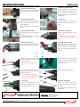
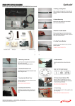
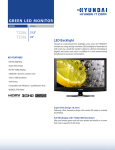
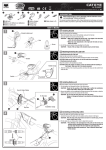
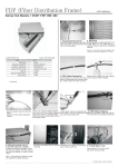
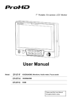
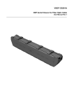
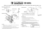
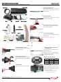
FIBER OPTIC SPLICE CLOSURE Dome Type Fiber optic Splice Closure (VSOF-BS604C) User manual Aerial Hanger Clamp Ass’y 1. Marking a Cutting Point Mark a sheath removing point on the cable with a piece of tape at a 120cm point from the cable cut end. Body 2. Sheath Removing Remove the cable sheath from the marked point using a sheath stripper. Base Tray Band TM Splice Tray Assy Remove plastic tape and dummy fillers tubes. After trimming off dummy filler tubes, clean the loose tube with jelly cleaner Heat Shrinkable sleeve Aerial Hanger Sand Paper Cable Tie 3. Cutting Tension Member Leave 8cm from the cable end and cut off the tension member. * Length of Tension Member: 8Cm. Cleaner Silver Foil Tape Silica Gel Protuction Tube 1 2 3 4 4. Inserting Heat Shrink Tuber Insert the cable into the heat shrink tube from the loose tube end. 5. Removing Loose tube & Inserting Protection Tube Leave 4cm from the cable end and remove the rest of loose tubes. Clean the cut area using jelly cleaner and insert fibers into the provided protection tubes after cutting into 24cm Cutting (Dual type) 6. Cutting Cable Inlet Ports Select the appropriate cable inlet ports and cut less than 3mm from the ports end with a Cutting (single type) saw. Note. Port VS Cable Diameter Port type Cable dia. A Single Ф12~ Ф17 B Single Ф12~ Ф24 C Dual Ф12~ Ф19 7. Cable Insertion 8. LAP Grounding Insert the cable into the inlet port from the Insert a LAP grounding connector tab into end. the LAP sheath deeply and clamp the cable sheath tightly with the other tab attached to the connector using pliers. * There is no need to do additional job for grounding tension member VISSEM OFC-BS604C-Manual Rev.0 TEL: 82-31-283-7852 All rights reserved by VISSEM Electronics Co. Ltd. FAX: 82-31-283-7844 FIBER OPTIC SPLICE CLOSURE Dome Type Fiber optic Splice Closure (VSOF-BS604C) User manual 9. Fixing Tension Member (TM) 10. Attaching protection Tube Place the TM on the TM Nut and close it Remove the protection tube leaving enough with the TM Bolt. Tighten it with bolts using a length for attaching it to the splice tray. Then hand. insert the protection tube into the inlet on the splice tray, attach the protection tube using a cable tie. 11. Splicing & Storing Fibers 12. Recording Splice fibers using an approved fiber splicing After the arrangement, close the tray lid, method. After the splice, insert sleeves in and record each splice on the index card on each slit accordingly. the lid. Coil surplus fibers in the tray in a figure 8 shape 13. Tying silica Gel and Trays. 14. Assembling the Closure Stack the trays using the connection parts Place the dome shaped cover onto the on the side bottom portion. Place the provided silica gel on the splice * Check the status of silicon gasket ring tray lid and tie them together. inserted in the slit of the dome shaped cover. 15. Band clamp connection 16. Heating Heat Shrink tube Fasten the dome shaped cover and the Rub the inlet ports and the cable with the bottom portion together with a band clamp provided sandpaper and clean them with a cleaner to allow the sealing adhesives inside of the heat shrink tube to bond to each side 5 6 7 8 Wrap the silver foil tape around the cable Push the heat shrink tube up to the cable 8cm from the inlet port to protect cable inlet port end, and heat the tube staring at sheath form the burner. the inlet port moving away from it while * Be careful not to damage the silver foil controlling the fire. tape When using dual type heat shrink tube, Split clip Heat shrink tube heating completed. insert the split clip as the figure shown before heating the tube Single * When heating the tube, heat the tube around the cable equally and don’t over heat on specific part of the tube Ground terminal Bonding wire Dual 17. Grounding 18. Hanger connection Connect the external bonding wire to the Connect ground terminal attached on the center of connecting part with bolts and nuts as the the inlet part using the ground bolt. figure shown. the hangers to the hanger Hang the closure on the wire properly using aerial hangers. VISSEM Electronics 235-2, Deokpyeong-ri, Majang-myeon, Icheon-city, Gyeonggi-do, Korea 467-812 www.opticube.co.kr Email: [email protected] Tel: 82-31-283-7852 Fax: 82-31-283-7844 VISSEM OPT-M0711 Printed in Korea VISSEM OFC-BS604C-Manual Rev.0 TEL: 82-31-283-7852 All rights reserved by VISSEM Electronics Co. Ltd. FAX: 82-31-283-7844