1
FLIR Sensors Manager
User Manual
Document Code:
MAN-IT-2008-003
Revision:
2.0
Date:
January 2010
Internal Code:
MT1003/2008v2.0
FLIR Networked Systems.
Av. Bruselas 6 - B2
28109 Alcobendas (Madrid) - Spain
Tel: +34 (91) 490 40 60 Fax: +34 (91) 662 97 48
PROPRIETARY INFORMATION
© FLIR Networked Systems, 2009
This document may only be reproduced partially or completely, archived, photocopied or transmitted
in any way through electronic media with previous written permission from FLIR Networked Systems.
It shall also be referenced when used as a source of information.
3
TABLE OF CONTENTS
1
2
3
4
5
4
INTRODUCTION
NEXUS OVERVIEW
FLIR SENSOR MANAGER LICENSES
FLIR SENSORS MANAGER INSTALLATION
FSM OPERATION
5.1 SENSOR NETWORK CONFIGURATION
5.2 SERVER DISCOVERY
5.3 APPLICATION PREFERENCES
5.4 SERVER STATUS AND BASIC MANAGEMENT
5.4.1 SENSORS PANEL
5.4.2 CONTROL PANEL
5.5 LICENSES MANAGEMENT
5.5.1 UPGRADING TEXT LICENSES
5.5.2 UPGRADING LICENSES IN A USB DONGLE
5.6 WINDOWS OPTIONS
5.6.1 “ALWAYS ON TOP” WINDOW
5.7 TOOLBAR
5.8 JOYSTICK SETUP
5.9 FLIR SENSOR MANAGER MAP
5.9.1 MAP LOADING AND CALIBRATION
5.9.2 MAP BASIC CONTROLS
5.9.3 MAP LOAD
5.9.4 MAP CALIBRATION
5.9.5 SENSOR GEO-REFERENCE
5.9.6 MAP ROTATION
5.9.7 MAP BACKGROUND OPACITY
5.9.8 SENSORS DISPLAY
5.9.9 SENSOR MANAGEMENT
5.10 VIDEO WALL SETUP
5.10.1 BASIC SETUP
5.10.2 CLEARING A VIDEO WALL
5.10.3 SETTING UP VIDEO POST PROCESSING (VPP)
9
9
9
10
11
11
11
14
15
15
18
19
19
20
20
20
21
21
23
23
23
24
26
30
34
36
37
42
43
44
49
50
5.11
5.12
5.13
5.14
5.15
5.16
5.17
5.18
5.19
5.20
5.21
5.22
5.23
5.24
5.25
5.26
5.27
5.10.4 SETTING UP THE VIDEO STATISTICS
5.10.5 FILE PLAYBACK
5.10.6 FRAME GRABBER PLAYBACK
5.10.7 VIDEO PLAYBACK MANAGEMENT
5.10.8 VIDEO PROFILES MANAGEMENT
5.10.9 CURSOR MODES
5.10.10AREA ADDITION
FSM NOTIFICATION
LOG
NMEA MONITOR
ALARM MONITOR
SCAN LISTS
5.15.1 CONFIGURING A SCAN LIST
5.15.2 LOADING AND STARTING A SCAN LIST
PANORAMA
NDVR MANAGEMENT
VPU MANAGEMENT
SURVEILLANCE MONITOR
5.19.1 AREAS
5.19.2 VMD
5.19.3 ACQUISITION
5.19.4 TRACKING
5.19.5 ALARMS
IMAGE POST-PROCESSING
5.20.1 FILTERS
5.20.2 STABILIZATION
ALARMS MANAGER
RADARS TRACKS PANEL
USERS MANAGEMENT
ADVANCED SENSORS CONTROLS
PROFILE MANAGER
MEDIA MANAGER
SOUNDS MANAGER
51
53
55
58
59
60
61
63
63
64
64
65
66
66
67
69
70
72
73
74
75
79
80
81
82
83
84
85
86
88
89
90
90
5
TABLE OF CONTENTS
APPENDIX A. SENSOR NETWORK CONFIGURATION
1 CHANGING THE CLIENT’S (HOST PC’S) IP ADDRESS
1.1 WINDOWS VISTA & WINDOWS 7
1.2 WINDOWS XP
91
91
91
91
APPENDIX B. SETTING UP USERS AND WORKGROUPS
1 SETTING UP USERS AND WORKGROUPS
1.1 CREATING ACCOUNTS (WINDOWS XP PROFESSIONAL)
1.2 SETTING UP USER GROUPS
(WINDOWS VISTA / 7 PROFESSIONAL)
1.2.1 CREATE A NEW USER ACCOUNT
1.2.2 ADD A USER ACCOUNT TO A GROUP
1.3 SETTING UP USER PRIVILEGES
92
92
92
APPENDIX C. ELECTRONIC STABILIZATION
1 INTRODUCTION
2 HARDWARE REQUIREMENTS
3 ESTAB APPLICATION GUIDELINES
3.1 PRINCIPLE OF OPERATION
3.2 ESTAB CONTROL PANEL IN FLIR SENSORS MANAGER.
3.3 SETTING UP THE STABILIZATION ROI
3.3.1 STABILIZATION EXAMPLE 1
3.3.2 STABILIZATION EXAMPLE 2
3.3.3 STABILIZATION EXAMPLE 3
3.4 ADJUSTING AMPLITUDE PARAMETERS
4 ADDITIONAL SETTINGS
4.1 SHOW BORDER
4.2 CONTRAST ENHANCER
6
95
95
96
96
98
98
98
98
98
98
99
100
100
101
101
102
102
102
5 TROUBLESHOOTING AND LIMITATIONS
5.1 INTEGRATION TIME
5.2 CPU USAGE
5.3 LIMITATIONS
5.3.1 NOISY VIDEO
5.3.2 VERY LOW RESOLUTION VIDEO
102
102
102
102
103
103
APPENDIX D. SETTING UP THE SURVEILLANCE MONITOR
104
1 INTRODUCTION
104
2 ITEMS REQUIRED
104
3 SETTING UP THE ENVIRONMENT
104
4 IMPORTANT CONCEPTS FOR VMD (VIDEO MOTION DETECTION)
AND TARGET ACQUISITION
104
5 SETTING UP A SURVEILLANCE SYSTEM USING VMD
106
106
5.1 AREA EDITION
110
5.2 ALARM MONITORING
111
5.3 FINE TUNING VMD PARAMETERS
6 TARGET ACQUISITION
111
6.1 SETTING UP A SURVEILLANCE SYSTEM USING
112
THE TARGET ACQUISITION ALGORITHMS
115
6.2 GLOBAL NOISE FILTER SLIDER
116
6.3 MIN AND MAX SIZE
117
6.4 CLUSTERING TARGET FRAGMENTS INTO A SINGLE TARGET
119
6.5 ACQUISITION AND DROP TIMES
7 PROFILES
120
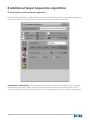
8 ADDITIONAL TARGET ACQUISITION ALGORITHMS
122
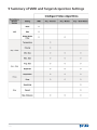
9 SUMMARY OF VMD AND TARGET ACQUISITION SETTINGS
124
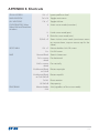
APPENDIX E. SHORTCUTS
125
7
8
1 Introduction
This manual will familiarize a user with the FLIR Sensors Manager (FSM) application, taking the
user through the most common operational steps. This document is based on a specific layout
of FSM, and may differ from the actual application, but the components and operating steps are
the same.
2 Nexus Overview
Nexus is a “plug- and- play” middleware tool allowing management of a wide variety of
sensors; from very basic sensors to complex, networked imaging integrated systems, including
radars, DVRs, I/O sensors, ground sensors, etc. The Nexus system is built over three main entities:
-
Server: the Server is connected to the devices, turning them into network
plug-and-play devices.
Client: the Client is the user interface for interacting in a network of sensors;
it could be FSM or a Nexus SDK-based application.
Development Tools: the Development Tools are a group of software components that
allow developers to easily code custom applications to manage and control the sensor
network. These include the following:
o Map: the Map control provides functions to build a graphical geographic
representation of the network.
o Software Development Kit: the SDK provides a library including a set of
functions to control the servers and get their current status.
o Video Player: the Video Player provides functions to play video from different
sources and to perform image post-processing and video analysis for
surveillance.
3 FLIR Sensor Manager Licenses
Certain FSM features will require a license to be active. The available licenses and the features
enabled are described below:
t
t
t
t
Demo License: When no license is loaded, the program runs in Demo Mode, allowing
command and control of one sensor at a time and one video per video wall.
Basic License: enables managing of up to 4 sensors and the geo-mapping features.
Pro License: enables all the features:
t 6QUPTFOTPST
t (FPNBQQJOH
t 4VSWFJMMBODF.POJUPS
t *NBHF1PTU1SPDFTTJOH
t 3BEBSDVFJOHBOEUSBDLTEJTQMBZ
t 7JEFPXBMMEJTQMBZ
Additional Sensor License: allows increasing the number of sensors that can be managed
simultaneously (up to 50 per workstation).
9
4 FLIR Sensors Manager Installation
To begin the installation process, choose Windows (XP or newer) PC or laptop based on the
following requirements.
Minimum Hardware Requirements:
*OUFM1FOUJVN1SPDFTTPS*7(PSIJHIFS
(#3".
(#'SFFIBSEESJWFTQBDFBWBJMBCMF
7("(SBQIJDT"EBQUFSXJUI
Minimum 1024x768 resolution
128 MB dedicated video memory*
Window DirectX Compatible
Real Time Video Overlay rendering capabilities
*ODPNQBUJCJMJUJFTEFUFDUFEXJUIDFSUBJOPOCPBSE*OUFM¥&YUSFNF(SBQIJDTDIJQTFUT
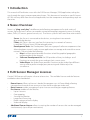
1. Insert the Installation CD and double click on the FSM Setup icon. The Installation Setup
window will open, click Next to continue.
2. Read the License Agreement and click I Agree to continue. In the next screen select the
components to be installed. Please note that FSM will not work if any of the components are
not installed. Unselecting components from the installation process is not recommended.
10
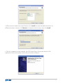
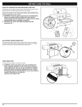
3. When asked to choose the install location, click Install to accept the default location. If a
different location is desired, click Browse to navigate to the location, then click Install.
4. The last component to be installed is the FLIR Video Player. Please note that the FSM
application relies on this player and it will not function without it.
11
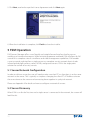
5. Click Next, read and accept the License Agreement and click Next again.
6. When the installation is complete, click Finish to close the installer.
5 FSM Operation
FLIR Sensors Manager offers a user friendly and straight forward interface that focuses on
usability and situational awareness. While minimizing operator workload, FSM still allows for full
control of its complete suite of surveillance and video management capabilities. FSM enables
a user to control anything from a single sensor to a complete security network that includes
infrared and daylight cameras, radars, NDVRs, and ground sensors. FSM is the single point
solution for control of security sensors.
5.1 Sensor Network Configuration
In order to talk to a sensor, the user will need to make sure their PC, or client host, is on the same
network as the sensor. This is typically as simple as changing the client PC’s IP Address to be on
the same subnet as the sensor and connecting them together in a physical network.
Please see Appendix A for details on how to configure a network of sensors.
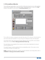
5.2 Server Discovery
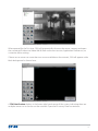
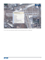
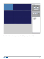
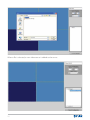
When FSM is run for the first time and a single sensor is connected in the network, the screen will
look like this:
12
When opened for the first time, FSM will automatically discover the sensor, connect and open
the streaming IR video into Video Wall 0. Refer to the next section, Application Preferences, to
customize these settings.
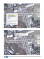
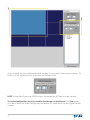
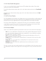
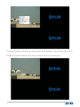
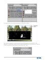
If there are no sensors or more than one sensor available on the network, FSM will appear with a
black background as shown here:
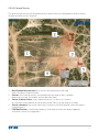
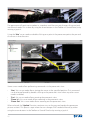
A FSM Notification displays in the lower right-hand corner of the screen, indicating there are
multiple sensors or no sensors on the network. Open the Discovery Panel to continue.
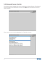
13
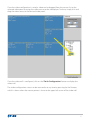
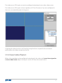
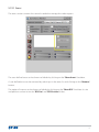
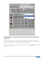
The Discovery Panel provides the functionality of adding servers to the Active Servers list. Click
on “Discovery” to open or close this panel. Servers can be added manually by entering the IP
address and port of the server and clicking on the “Add” button, or by performing a Network
Server Discovery. When the “Refresh” button is clicked, FSM will search the network for available
servers and list them under “Discovered Servers”. These servers can be added to the Active
Servers list by clicking the “>” button.
Once the servers are on the Active Servers list, they will be displayed in the Sensors Panel:
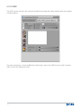
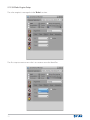
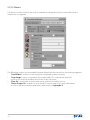
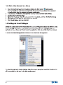
5.3 Application Preferences
For ease of operation, FSM is designed to discover, connect, gain control, and open a video
into a video wall by simply plugging in the server to the network and starting FSM. This is very
convenient if the user is running a “one sensor, one user” environment, but if the user runs
multiple sensors and works in a multi-user environment it is best practice to disable (deselect)
the automated features. In order to disable the automated features of FSM, go to the application
preferences panel by clicking on the “Edit” button on the menu bar and selecting “Preferences”.
In order to save any changes made in the preferences, the user must click the “Apply” button.
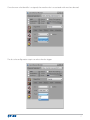
The “Behavior” section changes the actions that will be performed upon application start up.
t 5IFiDiscover Sensors On Start” feature will automatically discover sensors on the
network.
t 5IFiMake Discovered Sensors Active” feature will take a single discovered server and
add it to the active servers list. If a client is on a network with multiple servers, the user
will have to manually add the server to the active servers list.
t 5IFiConnect To Active Sensor” feature automatically connects to the active sensor
in the sensor’s panel.
t 5IFiRequest Control Of Active Sensor” feature automatically requests control over
the connected active server.
t 5IFiOpen Active Server Video On Video Wall 0” feature will open a single video
from the connected active server.
Note: If the server controls multiple camera sensors, only the first video source from the infrared
camera will be opened in the video wall.
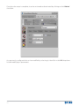
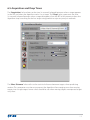
14
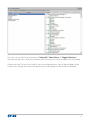
The “OSD” section allows setting the default OSD settings for the video windows when the user
creates a new video window inside of a video wall.
The “Change Language” section allows setting the application’s language. The changes will take
effect after restarting the application.
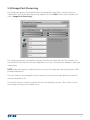
5.4 Server Status and Basic Management
Everything needed for basic sensor management is on the left side of the main window: the
Sensors Panel and the Control Panel.
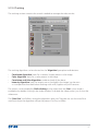
5.4.1 Sensors Panel
The Sensors Panel provides a view of the servers’ status and allows performing several
management operations.
A connection with a server can be established by right-clicking on the server name:
15
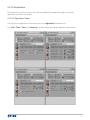
Once connected, the status of a server and of its devices is displayed.
Server Status:
t "HSFFOCPYOFYUUPUIFTFSWFSOBNFJOEJDBUFTUIBUUIFDMJFOUJTDPOOFDUFE
t "HSFFOCPYXJUIKPZTUJDLOFYUUPUIFTFSWFSOBNFJOEJDBUFTUIBUUIFDMJFOUJTDPOOFDUFE
and has control.
t "SFECPYOFYUUPUIFTFSWFSOBNFJOEJDBUFTUIBUUIFDMJFOUUJSFEUPDPOOFDUUP
the sensor but the connection could not be achieved.
t "HSFZCPYOFYUUPUIFTFSWFSOBNFJOEJDBUFTUIBUUIFTFSWFSJTOPUDPOOFDUFE
to the client.
Device Status:
t (SFFOJOEJDBUFTBEFWJDFJTDPNNVOJDBUJOH
t :FMMPXJOEJDBUFTBDPNNVOJDBUJPOQBDLFUIBTCFFOTFOUBOEJTBXBJUJOHBSFTQPOTF
t 3FEJOEJDBUFTUIBUUIFEFWJDFIBTOPUSFTQPOEFEGPSBEFGJOFEUJNFQBSBNFUFSBOEJT
probably either disconnected or not configured correctly.
To Request Control of a server and make active, double click on the selected sever name. A
KPZTUJDLOFYUUPUIFTFSWFSOBNFJOEJDBUFTDPOUSPMIBTCFFOPCUBJOFE BTTIPXOBCPWF
The control of a connected server can also be requested by right-clicking on its name and
selecting the Request Control option. A client may Lock Control over the server by right-clicking
and selecting Lock Control. This allows the user to automatically deny requests for control from
other clients. In some situations the user may need to use Request Control (Forced), which is
a request for control that cannot be denied even by clients with Lock Control selected. A forced
request is a request to control a server even if locked. However, the client using the server can
still deny the requesting client control.
16
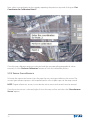
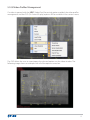
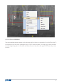
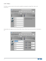
Right-clicking over a DLTV or an IR sensor displays the “Send to” menu which allows opening the
sensor’s video on one of the application’s video walls:
Please note that double-clicking on the sensor requests control over that sensor and sets it as
the active sensor as seen in the picture below. The active sensor is the sensor currently being
controlled by the client.
Placing the mouse pointer over the sensor displays a tooltip with information on the sensor:
The information displayed contains the name of the server, the host identifier, its geo-location
coordinates, and the status of the server (Stopped, Running or Unknown).
17
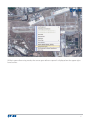
Right clicking on the sensor brings up a context menu that also allows user to set the server as
the active server, disconnect from the server, or even Stop/Start the server.
NOTE: Stopping the server is not recommended for normal users. Stopping the server will disable
command & control and digital video of the sensor over the entire network to all clients.
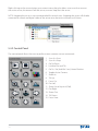
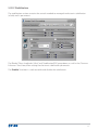
5.4.2 Control Panel
The control panel allows the user to perform most common sensor commands:
1.
2.
4.
6.
7.
8.
9.
10.
11.
12.
13.
14.
15.
18
Scan List Start.
Scan List Stop.
(P5P1SFTFU
Initialize Pan and Tilt.
(P5P4FU IPMEGPSTFD )PNF1PTJUJPO
Toggle Active Camera.
Zoom In.
Tilt Up.
Focus Far.
Pan Left.
Show Virtual Joystick (Pad).
Pan Right.
Zoom Out.
Tilt Down.
Focus Near.
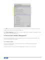
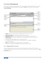
5.5 Licenses Management
The licenses management module allows for setting and checking the application licenses. The
License Manager can be displayed by clicking on the “View” menu button and selecting the
“License Manager”:
1.
2.
3.
4.
5.
6.
7.
8.
Get Id: displays the host identifier needed to generate a license string.
Load License File: loads a text file into the licenses text box.
Save License File: saves the contents of the licenses text box to the license file.
Check Licenses: checks the available licenses and displays the results in the licenses
check text box.
The licenses text box displays the current license string.
The dongle data fields display the current dongle data. If no dongle is plugged in,
these will be disabled.
Store: stores the data in the dongle data fields in the dongle.
The licenses check text box displays the result of the licenses check.
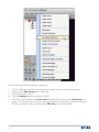
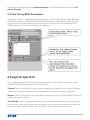
5.5.1. Upgrading Text Licenses
In order to upgrade the text license, the license string (typically a “license.txt” file) must be
copied and pasted into the licenses text box (item number 5) and saved by clicking on the “Save
License File” button.
19
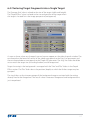
5.5.2 Upgrading Licenses in a USB Dongle
In order to upgrade a USB dongle with additional licenses, the license key (text string containing
six groups of numeric characters) must be typed in the dongle data fields (item number 6) and
stored in the dongle by clicking on the “Store” button.
Note: Permanent license strings can be attained by contacting a FLIR Applications
Representative
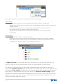
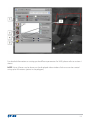
5.6 Windows Options
Right-clicking on any window’s title bar and selecting Display, will open a context menu to
change window settings:
The Fit options will resize the window to fit either its content or the screen.
The Aspect Ratio options ensure that the selected aspect ratio will be kept after a resize.
The Main Menu toggling option is available only for the main window and it shows or hides the
main menu.
5.6.1. “Always on Top” Window
If the users want to keep one particular window always visible, they can use the Always on Top
option. To do so, right-click on the window frame and select Always on Top:
20
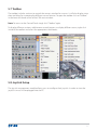
5.7 Toolbar
The toolbar includes sections to control the sensors attached to a server. It will also display status
data and allow for managing the different sensor features. To open the toolbar click on “Toolbar”
in the lower left hand corner of the FSM main window.
Note: To return to the Control Panel simply click “Toolbar” again.
To display different sections, add/remove control buttons, or display different status, right-click
inside of the toolbar and select the appropriate checkboxes.
5.8 Joystick Setup
5IFKPZTUJDLNBOBHFNFOUNPEVMFBMMPXTVTFSTUPDPOGJHVSFUIFJSKPZTUJDL*OPSEFSUPWJFXUIF
KPZTUJDLJUNVTUGJSTUCFQMVHHFEJOUPUIF1$
21
1.
2.
3.
4.
5.
Joystick selection drop down listTFMFDUTUIFKPZTUJDLUPCFDPOGJHVSFE
Save configuration button: stores the current configuration, making it active
for the rest of the application.
Axes configuration drop down list: set the axes actions. Axes can be tested
using the graphic bars beside the drop down list.
Button configuration drop down list: sets the buttons’ actions, allowing setting
different actions when the active camera is a DLTV and when the active camera is an IR.
POV configuration drop down list: sets the POVs’ actions, allowing setting different
actions when the active camera is a DLTV and when the active camera is an IR.
Note107 1PJOUPG7JFX JTOPUBWBJMBCMFPOBMMKPZTUJDLT
NOTE: Many commands in FSM are camera specific. Each camera operates independently
from the other. The left column represents the command sent when the IR camera is the active
camera. The right column represents the command sent when the DLTV camera is the active
camera.5.9
22
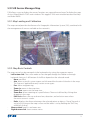
5.9 FLIR Sensor Manager Map
FSM allows a user to display the sensors’ locations on a geo-referenced map. To display the map,
click on “Map/Video” in FSM’s main window. This toggles FSM’s main window between the Map
and Video Wall 0.
5.9.1 Map Loading and Calibration
5IFNBQDPOUSPMQSPWJEFTUIFGFBUVSFTPGB(FPHSBQIJD*OGPSNBUJPO4ZTUFN (*4 DPNCJOFEXJUI
the management of sensors available on the network’s:
5.9.2. Map Basic Controls
The map control can be managed via the keyboard or by using the computer mouse:
- Left button click: The cursor mode can be changed through the Toolbar or through
keyboard shortcuts. A left button click effects depend on the selected mode
t None: no effect.
t Aim: allows a pan tilt system to pan and tilt toward the location clicked on in the map.
This feature is applicable to only certain sensor types.
t Pan: allows map panning.
t Zoom In: zooms in the map view.
t Zoom Out: zooms out the map view.
t Zoom Box: allows zooming to a specified area. The area is defined by clicking then
dragging in the map.
t Edit Area: allows the user to draw alarm, detection, and exclusion areas when
the active sensor is a radar.
t RulerEJTQMBZTUIFEJTUBODFCFUXFFOUIFTFMFDUFEQPJOUTPSPCKFDUT0OFPGUIFFOETJT
set by left-clicking on the map surface and the other is set by holding the “Shift” key
while left-clicking.
Mouse wheel: zoom in and zoom out.
Right button click: show context menu.
23
MAP KEYBOARD SHORTCUTS
A Arrow cursor mode (no action)
H Hand cursor mode (pan)
R Reticule cursor mode (aim)
Z/Shift+Z zoom in/out cursor mode
Mouse wheel Zoom in/out
Ctrl+mouse wheel Pan horizontally
Shift+mouse wheel Pan vertically
Alt+Mouse Wheel Map Rotation right
Ctrl+R
Alt+Mouse Wheel Map Rotation left
Ctrl+Shift+R
Crtl+N Reset Rotation
B /Shift+B Map Opacity (increase/decrease)
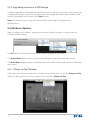
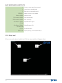
5.9.3 Map Load
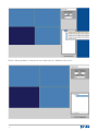
When no map has been loaded into FSM, the map module will appear black:
24
1.
2.
3.
Geographic coordinates: geographic coordinates of the point under the mouse position.
Logo: FLIR logo
Map surface: surface where the map will be displayed when loaded.
To load a map, right-click on the map surface and select the map file in the “Load Background”
menu:
NOTE: In order to effectively calibrate a map, the image files used must be North-up and
orthonormal. All map files must be placed in the maps folder of the application to be selectable.
5IJTGPMEFSJT=JOTUBMMBUJPO@GPMEFS=NBQw$VSSFOUMZ POMZiCNQwBOEiKQHwGJMFGPSNBUTBSF
supported.
25
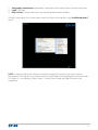
Once the map is loaded, it needs to be calibrated.
5.9.4. Map Calibration
The map calibration establishes a relation between the pixels of the map and the corresponding
geographical points on the earth. This allows the sensors’ geographical management tasks to be
performed using the features in the map controls.
To access the calibration mode, right-click on the map surface and select the “Map Background
Calibration” option:
26
Once in the map calibration mode, the map calibration panel is displayed:
27
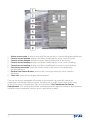
1.
2.
3.
4.
5.
Calibration steps reminder: description of how the calibration process is performed.
First point data: position of the first map point on the map file and the text fields
to enter the corresponding geographical coordinates.
Second point data: position of the second map point on the map file and the text fields
to enter the corresponding geographical coordinates.
Perform Calibration button: Calibrates the map.
Close link: closes the calibration panel.
The calibration process involves selecting two points of known geographical coordinates
and entering those coordinates into the Background Calibration window. For accuracy in the
calibration process it is important to select two distinct points as far from each other as possible.
Note: The user must know the exact Longitude and Latitude for these two points. This can be
BDRVJSFEMPDBMMZXJUIB(14 PSCZVTJOHSFBEJMZBWBJMBCMFUIJSEQBSUZNBQQJOHTPGUXBSFDBQBCMFPG
displaying coordinates for any given point.
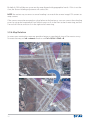
First, right-click on a point of the map for which the coordinates are known and select “Get
Coordinates for Calibration Point 1”:
28
Once a calibration point is selected, it is displayed on the map:
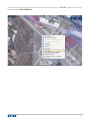
29
Now, select a second point on the map by repeating the previous step and clicking on “Get
Coordinates for Calibration Point 2.”
Once the two calibration points are selected and the corresponding geographical values
entered, click the “Perform Calibration” button to finish the calibration process.
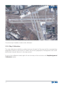
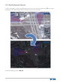
5.9.5 Sensor Geo-reference
To locate the connected sensor(s) on the map, the user must geo-reference the sensor. The
sensors’ geo-reference process can be performed in a few simple steps via the map control.
NOTE: To geo-reference a sensor, it must be the active sensor and control must be owned.
Once the active sensor is selected, right-click on the map surface and select the “Georeference
Sensor” option:
30
While in geo-referencing mode, the sensor geo-reference panel is displayed on the upper righthand corner:
31
1.
2.
3.
4.
5.
6.
7.
8.
Active sensor name: displays the name of the sensor that is currently being geo-referenced.
Current sensor location: displays and allows modifying the sensor current location.
Current sensor altitude: altitude in meters (above the ground) of the sensor.
Current sensor heading: displays and allows modifying the sensor current heading.
Current sensor leveling: displays and allows modifying the sensors’ current leveling.
Save to Sensor button: stores the current values in the sensor, thus performing
the geo-reference.
Restore from Sensor button: retrieves the current geo-reference values stored in
the sensor.
Close link: closes the sensor geo-reference panel.
One way the sensor’s geographical location can be entered is by manually typing the
coordinates into the geo-reference panel. The other way is to place the cursor on the map
in which the sensor is located then right-click and select “Get Coordinates for Sensor
Georeference”. This will take the latitude and longitude of the position clicked on by the mouse,
and place those coordinates into the sensor’s geo-reference panel.
32
Once the geo-reference values are committed by clicking on the “Save to sensor” button, the
sensor will be displayed on the map in the provided coordinates:
33
By default, FSM will place a sensor on the map aligned with geographical north. If this is not the
DBTF UIF4FOTPS)FBEJOHBEKVTUNFOUXJMMDPSSFDUUIJT
NOTE: the easiest way to correct a sensor heading is to match the camera image FOV content to
map content.
If the sensor cannot be mounted on a level plane to the horizon, a user can correct these leveling
errors by using the Longitudinal Error field to correct a tilt in the front-to-back mounting, and the
Transversal Error to correct a tilt in the right-to-left mounting.
5.9.6 Map Rotation
In some cases rotating the map may provide a better or more logical view of the area to survey.
To rotate the map, use alt + mouse wheel or use Ctrl + R/Ctrl + Shift + R.
34
To reset the map to its original position (North-up), the user can use Ctrl+N, or right-click on the
map and select Reset Rotation:
35
5.9.7 Map Background Opacity
5PBEKVTUUIFPQBDJUZPGUIFNBQCBDLHSPVOE DMJDLPOUIFNBQPODFUIFOQSFTTiB” to increase
the opacity. The map will get dimmer and the sensors will stand out:
To decrease opacity, press Shift+B.
36
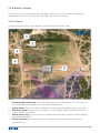
5.9.8 Sensors Display
The sensors that can be displayed on the map, usually have an associated set of graphics,
(depending on the sensor type) that will display the sensor status data.
5.9.8.1 General
Some of the map sensor status graphics are common to all sensor types:
1.
2.
3.
4.
5.
Disconnected sensor icon: the disconnected sensors are grayed out, as in the “mserver”
icon displayed on the upper left corner of the image above.
Sensor name: the sensor name is displayed on the map surface below the sensor icon.
Unknown sensor: sensors for which there is no associated image are displayed on the
map as a plain-colored dot.
Active sensor ring: the active sensor is displayed on the map surface by a plain-colored
ring around the sensor.
Sensor summary: the sensor summary is displayed when placing the mouse over
the sensor icon.
37
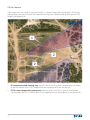
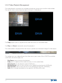
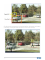
5.9.8.2 Cameras
If the sensor has any cameras associated with it, a camera’s expected viewing area is shown by
red and blue cones on the map. The expected viewing area is determined by the camera’s FOV,
height, and angle of tilt.
1.
2.
38
IR camera expected viewing area: the red cone is the IR cameras viewing area calculated
by the IR’s field of view (FOV), height of sensor and angle of tilt on the pan tilt.
DLTV camera expected viewing area: the blue cone is the DLTV cameras viewing area
calculated by the DLTV’s field of view (FOV), height of sensor and angle of tilt on the pan tilt.
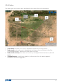
5.9.8.3 Radars
The radar-type sensor status data is displayed on the map surface as shown below:
1.
2.
3.
4.
Scan sector: the radar scan sector is displayed in green on the map surface.
Radar tracks: each radar track is displayed on the map surface including its identifier,
as a text label beside it, and a brief trail to show its history.
Radar track summary: the radar track summary is displayed when the mouse is placed
over it.
FSM Notification: a notification displays, indicating an alarm has been triggered
and which sensor has triggered it.
39
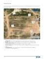
5.9.8.4 I/O Sensors
The I/O-type sensors are displayed on the map surface, including both the I/O box location and
the sensors location:
1.
2.
3.
4.
5.
40
I/O box icon: the sensor icon displayed on the map shows the I/O box location.
Sensors: the I/O sensors are displayed on the map as dots with an identifier label.
Sensor in alarm status: when an input sensor is in alarm, it is shown on the map
surrounded by a ring and the word “Alarm” can be read on its label.
Sensor summary: the sensor status data summary is displayed when the mouse is placed
over it.
FSM Notification: a notification displays, indicating an alarm has been triggered
and which sensor has triggered it.
5.9.8.5 Ground Sensors
The ground-type sensors are displayed on the map surface, including both the base station
location and the sensor’s location:
1.
2.
3.
4.
5.
Base Station Receiver icon: the sensor icon displayed on the map
shows the base station location.
SensorsUIF(SPVOETFOTPSTBSFEJTQMBZFEPOUIFNBQBTEPUT BHSBQIJD
depicting its range, if available, and an identifier label.
Sensor in alarm status: when a ground sensor is in alarm, it is shown
on the map surrounded by a ring and the word “Alarm” can be read on its label.
Sensor summary: the sensor status data summary will be displayed when the mouse
is placed over it.
FSM Notification: a notification displays, indicating an alarm has been triggered
and which sensor has triggered it.
41
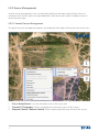
5.9.9 Sensor Management
Several sensor management tasks can be performed from the map. Some of these tasks are
common to all sensors, others are type dependant, and some may involve multiple sensors of
more than one type.
5.9.9.1 General Sensors Management
The general sensor management options are displayed when right-clicking over the sensor icon:
1.
2.
3.
42
“Set as Active Sensor”: sets the selected sensor as the active one.
“Connect”/“Disconnect”: allows managing the connection status of the sensor.
“Request Control”/“Release Control”: allows requesting/releasing control of the sensor.
5.9.9.2 Camera-type Sensors Management
The following actions can be performed over a camera-type sensor using the map:
- Aiming: being the active sensor a camera-type sensor and the cursor mode the “Aim” cursor
mode, left-clicking over the map surface will command the sensor to point to the geographical
coordinates the clicked map point stands for.
5.9.9.3 Radar-type Sensor Management
The following actions can be performed over a radar-type sensor using the map:
- Area creation: the radar areas can be created by selecting the “Edit Area” cursor mode.
5.10 Video Wall Setup
The video walls can be displayed by clicking on the “View” button on the toolbar, or by clicking
on the adequate panel header:
Once the video wall is displayed, it can be configured by entering the configuration mode. The
configuration panel is displayed by clicking on the “<<” button on the upper left corner of the
video wall. This button is visible only when the mouse is placed over its location.
43
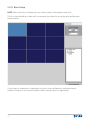
5.10.1 Basic Setup
NOTE: When no license is loaded, only one video window is allowed per video wall.
The first step to building a video wall is to organize the video tiles using the grid configuration
panel controls:
Once the grid is organized, a video player instance can be configured in a grid position by
double clicking on it; the selected video window changes color to a lighter blue:
44
The video window can be set up using the Video Configuration panel controls (2):
45
In this example we have configure the video window (1) to occupy 2 rows and two columns. To
do this, use the up/down arrows in the Row and Columns fields:
NOTE: If Video Post Processing (VPP) functions are needed, the VPP box must be checked.
The video configuration must be saved for the changes to be effective. The Save button
must be clicked in the Video Configuration box before any video source can be assigned to that
window
46
Once the video configuration is saved, a video can be dragged from the sensors list to the
selected video panel to assign the video source to the video player. To do so, simply click and
drag the video source to the desired video panel:
Once the video wall is configured, click on the “Finish Configuration” button to display the
video wall.
The video configuration screen can be returned to at any time by pressing the “<<” button,
which is shown when the mouse pointer is close to the upper-left corner of the video wall:
47
To clear a configured video panel from the video configuration window, click on it and then click
Delete in the video configuration box:
48
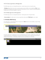
5.10.2 Clearing a Video Wall
To clear the video from a video wall, right click on the wall and select Clear. The video is cleared
from the window and the video stream is closed. Then the window returns to a black screen
displaying a FLIR logo.
49
5.10.3 Setting up Video Post Processing (VPP)
The VPP check box must be selected to use any of the video post processing functions, like the
Surveillance Monitor, Image Post Processing, or adding some of the On Screen Displays options
available in FSM. VPP can also be togged on/off from the context menu:
Resetting the VPP clears all created areas, filters or any other settings that make use of this
function.
50
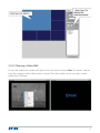
5.10.4 Setting up the Video Statistics
To get the video statistics associated with the video, right-click on the video window and select
Video Statistics:
The upper right corner of the video window begins to display the Frames per Second; clicking
on the arrow expands the displayed information:
51
VIDEO WALL KEYBOARD SHORTCUTS
A Arrow cursor mode (no action)
H Hand cursor mode (pan)
R Reticule cursor mode (aim)
Z/Shift+Z zoom in/out cursor mode (continuous zoom
on mouse down, stop on mouse up for the
video)
Ctrl+F/ mouse double-click Full Screen
Esc Exit Full Screen
52
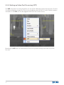
5.10.5 File Playback
Before a file can be configured to be played in the video wall, it must be assigned as a server
video source. Right-clicking on a server will show the context menu:
When the “Add Video From File” option is selected, a window prompting for the file to be
opened is shown:
53
When a file is selected, a new video source is added to the server:
54
The video source (“file” type) can now be configured to be played as any other video source.
The video source (“file” type) can be assigned to a DLTV or IR camera, if any were configured in
the server, or removed by right-clicking on it:
Assigning the video to a device will lead to having the device respond to the commands
performed on the video coming from the file.
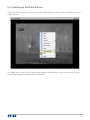
5.10.6 Frame Grabber Playback
Before a frame grabber can be configured to be played in the video wall, it must be assigned as
a server video source. Right-clicking on a server will show the context menu:
55
When a frame grabber is selected, a new video source is added to the server:
56
The frame grabber video source can now be configured to be played as any other video source.
The video source can be assigned to a DLTV or IR camera, if any were configured in the server, or
removed by right-clicking on it:
Assigning the video to a device will lead to having the device responding to the commands
performed on video coming from the frame grabber.
57
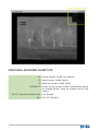
5.10.7 Video Playback Management
The video playback commands are available on both the context menu and the video toolbar.
The context menu can be shown by right-clicking on a video player:
The “Snap” option takes a snapshot of the video and stores it in the media folder.
The “Play” and “Pause” commands control the playback.
The video toolbar is displayed when the mouse is placed near the bottom edge of a video player:
The toolbar items vary depending on the video source type: stream, file or NDVR. The available
commands, from left to right, are:
t
t
t
t
t
t
58
Play/Pause: pauses/resumes the playback.
Snap: takes a snapshot of the video and stores it in the media folder.
Select Speed: sets the playback speed. (NDVR only)
Skip Backwards: skips as many minutes as the speed factor backwards. (NDVR only)
Skip Forwards: skips as many minutes as the speed factor forwards. (NDVR only)
Seek: allows setting the playback to any position. (NDVR and files only)
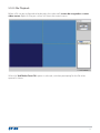
5.10.8 Video Profiles Management
If a video is opened with the “VPP” (Video Post-Processing) option enabled, the video profiles
management and the OSD (On Screen Display) options will be available in the context menu:
The OSD allows the user to superimpose the selected options on the video window. The
following image shows an example with all of the options turned on:
59
5.10.8.1 Video Profiles Management
A user can save and load video settings from any VPP-enabled video window. These video
settings are stored in the video profile.
To save the video window settings, right-click in the video window and select the “Save Profile”
option.
To load previous video window settings, right-click in the video window and select the “Load
Profile” option.
5.10.8.2 On-Screen Display
The OSD dropdown menu displays the available items that can be overlaid on a video image: the
timestamp of the sensor, the sensor name, the sensor’s geographical location, the azimuth and
elevation of the sensor if applicable, the FOV of the video source, and a Heads-Up Display.
Each time a video configuration is created, the OSD values are set to the defaults configured
in the Preferences panel (See section 5.3). However, the OSD settings are local to each video
configuration and this menu allows customizing the OSD individually.
5.10.9 Cursor Modes
Some cursor modes allow performing commands to the sensor via the video wall video players:
t
t
t
t
t
iAim”: this cursor mode allows aiming the sensor at the specified video position. If the shift
key is pressed and the video post-processing is enabled, this cursor mode allows enabling
the video tracker. (Only for PT cameras)
iPan”: this cursor mode allows panning and tilting using the video player surface as if it
were a touchpad. (Only for PT cameras)
iZoom In”: this cursor mode allows sending “Zoom In” commands to the sensor the video
is associated to.
iZoom Out”: this cursor mode allows sending “Zoom Out” commands to the sensor
the video is associated with.
iEdit Area”: this cursor mode allows performing the area creation process inside of
the video window.
The user can select the cursor mode using the icons on the Toolbar, or from the context menu in
any video player window. To do so, right-click in the image, select Cursors, and select the one to
use:
60
5.10.10 Area Addition
The area addition process begins with selecting the Edit Area cursor mode. Once the “Edit Area” is
selected, the user can draw a polygon area in a VPP video window. Clicking in the video window
sets the beginning point in the area and allows the user to select the type of VPP area they want
to draw:
61
When the area type is selected, new area vertexes can be added by clicking on the video surface:
Double-clicking will set the last area vertex and finish the area creation process:
62
The area identifier (“0”) will appear when the area creation process is finished and the polygon
closed. Subsequent areas are identified with consecutively numbered area identifiers (i.e. “1”, “2”,
etc.). The polygon is always closed, even during the creation process, unless the selected area
type is “Wire.”
NOTE: For detailed instructions on how to set up an area, please refer to Appendix D: setting
up the Surveillance Monitor.
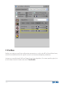
5.11 FSM Notification
The FSM Notification box will appear in the lower right-hand corner of the PC screen when a
notification occurs. The notification box informs the client for many types of events. When the
client is performing an action with another client they will receive a notification such as a request
for control. The notification box also notifies the client when they attempt to perform a unique
sensor feature such as performing a NUC (non-uniformity correction) with a thermal camera
sensor. The client uses the notification box as a tool to help manage their network and sensors.
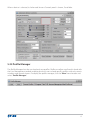
5.12 Log
The log panel displays the application status messages:
The log messages can be filtered by string and by server. These options can be shown or hidden
via the “Filters” button.
If the “Notify Log Messages” check box is checked, all log messages will also appear as a FSM
Notification.
63
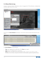
5.13 NMEA Monitor
The NMEA Monitor displays the NMEA sentences received from the sensors:
5IF/.&"TFOUFODFTDBOCFGJMUFSFECZTUSJOHBOECZTFSWFSKVTUMJLFUIFMPHNFTTBHFT5IFTF
options can be shown or hidden via the “Filters” button.
5.14 Alarm Monitor
The Alarm Monitor displays both the alarms received from the sensors, and the alarms that result
from video post-processing:
The alarms can be filtered by string and by server. These options can be shown or hidden via the
“Filters” button.
64
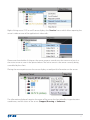
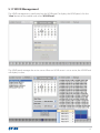
5.15 Scan Lists
Scan list management can be performed using the shortcuts on the “Scan List” section of the
toolbar or via the Presets Manager.
To open the Presets Manager, click “View->Presets Manager”:
The Presets Manager only communicates with the active server. When a server is set as active,
the Presets Manager will display that server’s current scan list:
Certain sensors can store and load scan lists directly from the sensor itself. The “Load”, “Save” and
“Delete” buttons, and the drop down box located in the upper left-hand corner of the Presets
Manager, are used to manage these actions.
65
5.15.1 Configuring a Scan List
The client can create a scan list by using the “Add” button of the Presets Manager. The pan, tilt,
zoom, and focus position of a camera sensor are placed into a scan list point. The client also can
manually enter in the azimuth, elevation, FOV, and focus positions as a scan list point.
If the user pan, tilts, zooms, and focuses the camera to a desired location, then presses the “Add”
button, the current position is then stored into the scan list as the next available scan list point.
The “Add” button will use the selected “Time” & “Speed” parameters into the new scan list point.
The “Time” parameter represents how long the camera will stay at its current position, in seconds,
until the camera begins moving to the next position.
NOTE: The “Time” counter starts once the pan tilt reaches the desired location. The “Time”
counter will not account for the time it takes to zoom and focus the cameras. This will need to be
accounted for when configuring a scan list.
The “Speed” parameter represents the velocity, denoted in degrees per second, the pan tilt will
move to reach the next point in the scan list. This is restricted by the velocity limits of the pan tilt
unit.
The “Camera” parameter denotes which camera is currently being run and configured with the
scan list. This is important when configuring the scan list since pushing the “Add” button will take
the zoom and focus positions from the camera selected in the “Camera” parameter.
The “Mode” parameter indicates how the scan list points are stored and read from the sensor. In
almost every situation the “Az/El” mode is used.
All points on a scan list can then be manually edited, or entered by checking the “Edit” checkbox.
Once the user is done manually editing/entering their changes, they should uncheck the “Edit”
checkbox in order for those changes to be saved.
The “Refresh” button updates the scan lists data. This is intended for use in older servers that do
not support the automatic update feature.
To remove all the points from a scan list hit the “Clear” button.
To remove only a single point, hit the “Delete” button
5.12.2 Loading and Starting a Scan List
Presets can be saved to a file by clicking on Save to Local File. The user can also load presets
using the Load From Local File button.
The “Start” button performs two tasks when pressed; first, it will load the current scan list in FSM
into the sensor, second, it will start the scan list. The scan list is managed in the sensor so it will
continue running if the sensor is disconnected from the network, or FSM is closed.
66
The “Stop” button stops the current scan list.
The “Go To” parameter can be used when a user would like to go to a specific scan list point.
5.16 Panorama
This function allows for creation of a panoramic view using either the IR or the DLTV camera. A
user can then double click on any spot of the panorama image and the pan tilt will aim to that
spot.
The panoramic view is created using the Panorama control window. To display the Panorama,
click the “View” menu button and select “Panorama”:
Right-clicking on the Panorama surface displays the panoramic view, creation and updating
options:
NOTE: The user must first open the video stream into a video wall window before attempting to
create the panorama; otherwise, the panorama will not operate.
Once an option is selected, the sensor will turn through the selected number of degrees and
take a series of consecutive snapshots, which are then automatically stitched into a panoramic
view:
67
The panorama will continue to update its snapshots until the user puts the pan tilt sensor back
into Manual mode. This is done by using the arrow buttons in the Toolbar or Control Panel, or by
NPWJOHBKPZTUJDL
Using the “Aim” cursor mode or double-clicking on a point in the panorama points the pan and
tilt sensors in that direction:
Some cursor modes allow performing commands via the panoramic view:
t
t
t
t
iAim”: this cursor mode allows aiming the sensor at the specified position. This command
can also be performed by double-clicking on the panoramic view when any other cursor
mode is enabled.
iPan”: this cursor mode allows panning the panoramic view.
iZoom In”: this cursor mode allows zooming in the panoramic view.
iZoom Out”: this cursor mode allows zooming out the panoramic view.
When selected, the “Update” function continues to scan the area and update the panorama
picture sections. This process stops when the user changes PLAT mode to Manual, by either
VTJOHUIFBSSPXCVUUPOTJOUIF5PPMCBSPS$POUSPM1BOFMPSCZNPWJOHBKPZTUJDL
68
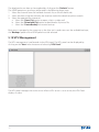
5.17 NDVR Management
The NDVR management is performed via the NDVR panel. To display the NDVR panel, click the
“View” button on the toolbar and select “NDVR Panel”:
The NDVR panel manages the active server. When an NDVR server is set as active, the NDVR Panel
will display its data:
69
The displayed server data can be updated by clicking on the “Refresh” button.
The NDVR operations are always performed in the following three steps:
1. Select the channel from the available channels list on the left hand side.
2. Select the date using the calendar, the time bar and/or the date/time picker controls.
3. Select the appropriate command:
a. Select the “Open Clip” option to open a clip in a video wall.
b. Select the “Download Clip” option to download a clip into a file.
c. Select the “Create Backup” to create a backup.
Backups are managed in the same way as the clips are. In order to access the available backups,
the “Backups” option of the NDVR panel must be selected.
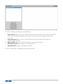
5.18 VPU Management
The VPU management is performed via the VPU panel. The VPU panel can be displayed by
clicking on the “View” menu button and selecting “VPU Panel”:
The VPU panel manages the active server. When a VPU server is set as active, the VPU Panel
displays its data:
70
The VPU available commands are the following:
1.
2.
3.
4.
5.
Open Source: opens the source video stream that is being processed in the selected VPU
channel on the selected video wall window. The source server must be in the active
servers list.
Open Recasted: opens the recasted video of the selected video channel on the
selected video wall tile.
Apply profile: applies the selected profile to the selected channel.
Download Profile: downloads the selected profile.
Upload Profile: uploads and applies a profile.
The VPU alarms data is displayed in the alarms text box.
71
5.19 Surveillance Monitor
The surveillance monitor allows a user to perform video processing tasks on any video windows
which have VPP enabled. The surveillance monitor can be displayed by clicking on the “View”
button of the toolbar and selecting the “Surveillance Monitor” option:
The surveillance monitor manages the selected video channel. The channels can be selected via
the channel selection drop down list or by clicking on the adequate video wall video player.
Only video channels that were opened with the video post-processing (VPP) can be selected.
Please refer to section 5.10.3. Setting up Video Post Processing.
The main features are managed with the common controls placed right below the channel
selection drop down list.
The specific features controls are placed in the corresponding sections. The sections can be
accessed by clicking on the sidebar icons.
NOTE: For detailed information on surveillance monitor parameters and settings please refer to
APPENDIX D: Setting up the Surveillance Monitor.
72
5.19.1 Areas
The areas section contains the controls needed to manage the video regions:
The user-defined areas can be shown or hidden by clicking on the “Show Areas” checkbox.
A user-defined area can be removed by selecting it in the areas list and clicking on the “Remove”
button.
The region of interest can be shown or hidden by clicking on the “Show ROI” checkbox. Its size
and position can be set via the “ROI Size” and “ROI Position” sliders.
73
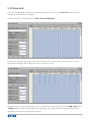
5.19.2 VMD
The VMD section contains the controls needed to manage the video motion detection regions
and parameters:
The area parameters can be modified by selecting an area in the VMD areas list and using the
sliders to set the adequate values.
74
5.19.3 Acquisition
The acquisition section contains the controls needed to manage the target acquisition
algorithms and the rules engine.
5.19.3.1 Algorithms Setup
The acquisition algorithm can be selected in the “Algorithm” drop down list.
The “Size”, “Time”, “Slow” and “Intensity” sections allow setting the algorithms parameters:
75
5.19.3.2 Rules Engine Setup
The rules engine is managed via the “Rules” section:
The first step to create a new rule is to create a new rule identifier:
76
Once the new rule identifier is assigned, the area the rule is associated with must be selected:
The last rule configuration step is to select the rule trigger:
77
Once the rule setup is complete, it can be activated or deactivated by clicking on the “Active”
checkbox:
Any previously configured rule can be modified by selecting its identifier in the “Id” drop down
list and modifying its parameters.
78
5.19.4 Tracking
The tracking section contains the controls needed to manage the video tracker:
The tracking algorithm can be selected via the “Algorithm” group box radio buttons:
t
t
t
t
Correlation Algorithm: looks for a contour (shape) pattern in the image.
Color Algorithm: looks for a color pattern in the image.
Correlation and Color Algorithm: combines both of the above.
Intensity Algorithm: looks for targets over a threshold in the image (can be seen
as a temperature threshold when working with an IR). Applies only to IR cameras.
The tracker can be enabled by Shift+clicking on the video while the “Aim” cursor mode is
FOBCMFEPSCZEPVCMFDMJDLJOHJOUIFWJEFPXJOEPX5PEJTBCMFUIFWJEFPUSBDLFS KVTUDMJDLPOUIF
video once.
The “Gate Size” scroll allows setting the algorithm’s gate size. The gate size sets the size of the
area from where the algorithm will get the pattern it will try to follow.
79
5.19.5 Alarms
The alarms section contains the controls needed to manage the actions to be taken when a
video alarm is triggered:
The following actions can be enabled to be performed on the event of an alarm being triggered:
t iSend E-Mail”: sends an e-mail using the configured accounts settings.
t iSnap Image”: stores a snapshot in the media folder. This snap can be attached
to the sent e-mails by enabling the “Attach Snap” check box.
t iSlew On”: commands an associated sensor to aim at the alarm source.
t iAlarm Output On”: enables an associated I/O sensor output. For more information
on the surveillance monitor parameters, please refer to Appendix D.
80
5.20 Image Post-Processing
The image post-processing module allows managing the image filters and the electronic
stabilization. To view the post-processing module, click the “View” button of the toolbar and
select “Image Post-Processing”:
The image post-processing module manages the selected video channel. The channels can
be selected via the channel selection drop down list, or by clicking on the adequate video wall
video player.
NOTE: To be selectable, the video channel must have the video post-processing option (VPP)
enabled beforehand.
The main features are managed with the common controls placed right below the channel
selection drop down list.
The specific features controls are placed in the corresponding sections. The sections can be
accessed by clicking on the sidebar icons.
81
5.20.1 Filters
The filters section contains the controls needed to manage the image filters layers and
parameters:
If parameters are applied to the selected filter, these will be shown beside the filters drop down
list:
82
5.20.2 Stabilization
The stabilization section contains the controls needed to manage the electronic stabilization
(eStab) and its parameters:
The “Border,” “Max. Amplitude (%fov)” and “Stabilization ROI” group boxes, as well as the “Contrast
Enhancer” check box, allow setting the electronic stabilization parameters.
The “Enable” checkbox is used to enable and disable the stabilization.
83
5.21 Alarms Manager
The alarms management module allows for acknowledging, and deleting alarms:
The alarms are stored in a database file in the log folder. Any change will immediately affect the
alarms database file. This file can be exported by clicking on the Create Report button. The file is
exported as an .XML file, which can be opened with several applications, e.g. Microsoft Excel™.
NOTE: The Alarms database is automatically backed up in an XML file and the running database
is cleared every 1000 alarm events.
84
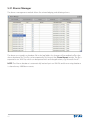
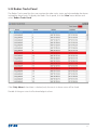
5.22 Radars Tracks Panel
The Radars Tracks panel lets the user monitor the radar tracks status and acknowledge the alarms
initiated by those tracks. To display the Radars Tracks panel, click the “View” menu button and
select “Radars Tracks Panel”:
If the “Only Alarms” check box is checked, only the tracks in alarm status will be listed.
Double-clicking on a track will acknowledge its alarm.
85
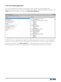
5.23 Users Management
The Users Management module lets the Administrator set the user groups application
permissions and restrictions. The Users Management module can be displayed by clicking on the
“View” button of the toolbar and selecting “Users Management”:
By default the Users Management module is disabled leaving all the features in FSM enabled for
any given user. To enable the Users Management module, the user must first create a Windows
group on the local PC titled “Nexus Admin.” Once this group exists, members of the Nexus
Admin group will be allowed to configure other user groups permissions and restrictions.
86
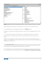
NOTE: Members of the Nexus Admin group will always have all available FSM features enabled.
Selecting a group in the groups list will display the current permissions on the features list.
The available groups can be updated by clicking on the “Refresh” button.
The features list displays the available application controls and the manageable features in each
control.
Un-checking a feature element will disable the corresponding feature while un-checking a
control element will disable all the features of the corresponding control for that particular
group.
While the Users Management module is open, the permissions of the selected group will be
applied in the application. This way an administrator can test the set permissions without having
to log back in as another user.
The “Current User Setup” group displays the permissions of the current user. When this element
is selected, permissions cannot be modified. In order to modify the permissions of the current
user, the permissions of the groups the user belongs to must be set.
Users belonging to more than one group will share the permissions of all the groups to which
the user belongs. For more information please refer to Appendix B: Setting up User Privileges.
87
5.24 Advanced Sensors Controls
The advanced controls manager allows accessing the devices advanced features. The advanced
controls manager can be displayed by clicking on the “View” button and selecting “Advanced
Sensors Controls”:
When a server is set as active, the drop down list is filled with its devices:
88
When a device is selected, its Advanced Sensors Controls panel is shown, if available:
5.25 Profile Manager
The Profile Manager lets the user load and save profiles. Profiles are often used hand in hand with
the User Management module enabling low level users to load specific profiles with only certain
windows and controls shown. To display the profile manager, click the “View” menu button and
select “Profile Manager”:
89
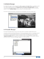
5.26 Media Manager
The Media Manager lets the user see a list of files stored in the Media folder, i.e snapshots saved
from video, typically located at C:\Program Files\FLIR Sensors Manager\media, although
it can be any other folder the user selects. If the user wishes to use another folder to store the
media, click the Set Root Folder button to select it as the default folder.
Any item can be previewed by clicking on the list displayed on the left window pane.
5.27 Sounds Manager
The Sounds Manager allows the user to assign specific sound files to application events
(currently to Alarms and Video Wall events). In the example below, the user is assigning a sound
to the Alarm function by selecting Alarm, then clicking on the drop down arrow to select a
sound file from the loaded files. To add a sound file to the sounds drop down list press the
“Import Sound File” button to browse to and then import a sound file from another folder on
the local system. FLIR Sensors Manager supports .wav and .mp3 files.
90
APPENDIX A. Sensor Network Configuration
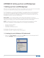
1 Changing the Client’s (Host PC’s) IP Address
1.1 Windows Vista & Windows 7
1. Navigate to Network & Sharing Center located in the Control Panel/Network & Internet/
Network & Sharing Center under the Start menu of the PC.
2. Click on the Local Area Connection Link (or appropriate source) for the internet connection
to the network. The Local Area Connection window will appear then select the Properties
button.
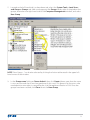
3. Once the Properties window opens. Select Internet Protocol Version 4 (TCP/IPv4) from the list.
Then select the Properties button.
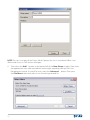
4. Select the Use the following IP address: tab. Under the IP address: tab write in the IP address
of the Nexus Server then change the last digits to be some other number than the Server’s IP
ending digits; between 0-255.
Example:
Nexus Server’s IP Address: 192.168.250.101
PC’s IP Address: 192.168.250.55
Then in the Subnet mask: “255.255.255.0”.
1.2 Windows XP
1. Navigate to Network Connections located in the Control Panel under the Start menu of the
PC.
2. Right click on the LAN or High-Speed Internet connection being used to communicate with
the Nexus Server and select Properties.
3. Next select the Internet Protocol (TCP/IP) tab and press the Properties button directly below
the TCP/IP tab, as seen in figure 17 below.
4. Select the Use the following IP address: tab. Under the IP address: tab write in the IP address
of the Nexus Server then change the last digits to be some other number than the Server’s IP
ending digits; between 0-255.
Example:
Nexus Server’s IP Address: 192.168.250.101
PC’s IP Address: 192.168.250.55
Then in the Subnet mask: “255.255.255.0”.
Note: These instructions are for a typical installation. Individual installations may require
additional network settings to be changed. If in doubt, contact your network administrator
Setting up Users and Workgroups
91
APPENDIX B. Setting up Users and Workgroups
1 Setting up Users and Workgroups
When first starting the application all features are enabled. A user may wish to set up user group
restrictions to control the functionality, look, and feel of FSM for some users.
The FSM application uses the Microsoft Windows™ user group infrastructure to manage users.
Users can then be assigned privileges which determine their level of access and control of
the application using FSM’s User Management feature. The user group that enables the User
Management feature is the Nexus Admin group.
Nexus Admin - Once created, members of this group will be allowed to use the User
Management feature in FSM, and in doing so can create restrictions for any other groups. This
allows restrictive rights to users who are not members of the Nexus Admin group.
NOTE: The following MS Windows versions do not provide groups management and the
permissions management will be disabled for users running any of the following:
t
t
t
8JOEPXT91)PNF&EJUJPO
8JOEPXT7JTUB4UBSUFS
)PNF#BTJDBOE)PNF1SFNJVN
For Windows XP setup instructions, see Section 1.1
For Windows Vista and 7 setup instructions, see Section1.2.
1.1 Creating Accounts (Windows XP Professional)
1.
92
Right click on My Computer, located under the Start menu or on the desktop of the PC,
and select Manage as shown in the figure below:
2.
Located on the left hand side is a drop down tab; select the System Tools> Local Users
and Groups> Groups tab. Add a new group to the Groups tab by right clicking below the
groups, located on the right hand side of the Computer Management window, and select
New Group…
NOTEi/FX(SPVQywDBOBMTPCFTFMFDUFECZDMJDLJOHUIF"DUJPOUBCMPDBUFEJOUIFVQQFSMFGU
hand corner of the window.
3.
In the Group name field type “Nexus Admin” then click Create (please note that the name
is case sensitive and that it must be typed exactly this way). This group is for the users who
need administrative rights in controlling the User Management feature in FSM. Once the
groups have been created, click Close to exit the New Group.
93
NOTE: If a user is not part of the “Nexus Admin” group, this user is considered a‘Basic User’
(Resitricted Access in FLIR Sensors Manager).
4.
94
Then select the Add… button in the bottom left of the New Group window. Then select
the appropriate users who need administrative rights regarding setting FSM’s User
Management control. To search for users select the Advanced… button. Then press
the Find Now button and select a user from the generated list.
The user can use the Features buttons to “Select All”, “Select None” or “Toggle Selection.”
Alternatively, the user can pick and choose which functions to assign to a particular user group.
Please note that “Current User Setup” is not an actual group but a view of the privileges of the
current user, taking into account the permissions of the groups to which the user belongs.
97
APPENDIX C. Electronic Stabilization
1 Introduction
This appendix describes the electronic stabilization (eStab) functionality included in FLIR Sensors
Manager. eStab is available only in the Pro License version.
2 Hardware Requirements
CPU power requirements for eStab will depend on the format (compressed,
uncompressed) and input resolution of the video and the number of post processing filters
added by the user.
"TBHVJEFMJOF BO*OUFM1(I[)ZQFSUISFBEJOHQSPDFTTPSXJUIBIJHIQFSGPSNBODFWJEFPDBSE
XJMMCFDBQBCMFPGEFDPNQSFTTJOHBOEEJTQMBZJOHBO.1&('VMM$*'WJEFPXJUIF4UBC XJUIOP
PUIFSQPTUQSPDFTTJOHGJMUFSTBEEFE"1FOUJVN$PSF%VP(I[XJMMCFBCMFUPPQFOB'VMM$*'
video with eStab and a median filter, or two or more of the other available filters.
NOTE: 4CIF resolution is 704 x 480 for NTSC systems and 704 x 576 for PAL systems.
5IFHSBQIJDTDBSE 7(" NVTUCF%JSFDU9DPNQBUJCMFBOEIBWFOPMFTTUIBO.#PG
dedicated RAM. Several modern chipsets from Nvidia™ and ATI™ have been tested with good
results.
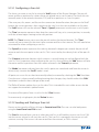
3 eStab Application Guidelines
3.1 Principle of Operation
There are two ways to use eStab: fully automatic mode and semi-automatic mode. The operating
mode is selected by choosing the Border mode. If Border mode is set to Dynamic the algorithm
XJMMBVUPNBUJDBMMZBEKVTUUIFTUBCJMJ[BUJPOQBSBNFUFSTUPUIFWJCSBUJPOTDIFNBJOUIFJNBHF*OUIJT
case the Max amplitude sliders are ignored.
*G#PSEFSNPEFJTTFUUP4UBUJD UIFOUIF.BYBNQMJUVEFTMJEFSTXJMMIBWFUPCFNBOVBMMZBEKVTUFE
by the user to match the vibration’s dynamic range on the video.
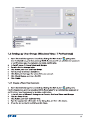
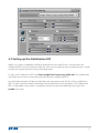
3.2 eStab Control Panel in FLIR Sensors Manager.
5PBEKVTUUIF4UBCJMJ[BUJPOQBSBNFUFSTJO'-*34FOTPST.BOBHFSDMJDLView>Image PostProcessing>eStab tab. The following image shows the layout of the different controls in the
current version of FLIR Sensors Manager:
98
3.3 Setting up the Stabilization ROI
Ideally, no camera symbology should be displayed on the video. If this is not possible, the
Stabilization ROI can be used to exclude any static text or logo from the computing area, in order
to optimize the performance of the eStab algorithms.
5PBEKVTUUIF4UBCJMJ[BUJPO30*DMJDLView>Image Post-Processing>eStab tab. The Stabilization
DIFDLCPYNVTUSFNBJOVODIFDLFEXIJMFBEKVTUJOHUIFTUBCJMJ[BUJPO30*
Any black/blank border will be excluded from the computing area (left out of the stabilization
ROI), in order to allow enough information for the algorithm to work properly. The Stabilization
ROI can be hidden once setup is completed. eStab can now be enabled by clicking on the
enable check box.
99
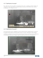
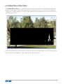
3.3.1 Stabilization Example 1
This video shows the most adverse situation for eStab. Static symbology and black border are
still present in the image. The first step should be to remove or minimize the static camera
symbology on the image (declutter).
3.3.2 Stabilization Example 2
*OUIJTQJDUVSFUIFDBNFSBTZNCPMPHZIBTCFFOSFNPWFEBOEUIFTUBCJMJ[BUJPO30*JTBEKVTUFE
to avoid the black border on the left. Video contrast is very low, making this image a good
candidate to enable the Contrast Enhancement feature. Doing this will not show any difference
in the displayed video but will highly improve the performance of the eStab algorithm.
100
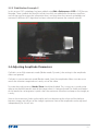
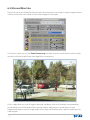
3.3.3 Stabilization Example 3
In this picture OSD symbology has been added using Edit->Preferences->OSD in FLIR Sensors
Manager. These symbols do not affect eStab since they are added after the processing filters,
and can be used to restore the information that is missing when the camera symbology was
SFNPWFE"EJGGFSFOU"($BMHPSJUINIBTCFFOTFMFDUFEUPJNQSPWFUIFDBNFSBTDPOUSBTU
3.4 Adjusting Amplitude Parameters
If eStab is set to fully automatic mode (Border mode: Dynamic), the settings in the amplitude
sliders are ignored.
If eStab is in semi-automatic mode (Border mode: Static) the amplitude sliders must be set to
match the vibration magnitude on x and y axis of the video.
5PNBLFUIFTFBEKVTUNFOUT Border Show should be disabled. This is necessary in order to be
BCMFUPTFFUIFCMBDLCPSEFSBSPVOEUIFJNBHFXIFOJUJTCFJOHBEKVTUFE5IFXJEUIBOEIFJHIU
of this border has to be greater in pixels than the maximum vibrations to damp on the image, on
x and y.
Start on the maximum (sliders to the right) and start decreasing the value until the balance
CFUXFFOJNBHFTJ[FTUJMMOFTTPGUIFJNBHFJTPQUJNVN/PUJDFUIBUBNQMJUVEFDBOCFBEKVTUFE
independently for X and Y axis.
101
4 Additional Settings
4.1 Show Border
This setting can be used when eStab is in semi-automatic mode (Border mode: Static) and the
User cannot afford missing any portion of the field of view while the image is being stabilized
(maximum situational awareness). It is also useful to confirm that stabilization is working
properly.
4.2 Contrast Enhancer
On low contrast situations, especially on IR cameras, a contrast boost may be necessary for eStab
to deliver optimum performance. This is achieved by activating the Contrast Enhancer checkbox.
Enabling contrast enhancement will not show any difference in the displayed video but will
highly improve the performance of the eStab algorithm. Contrast enhancement is never
recommended for stabilizing DLTV (color) video images.
5 Troubleshooting and Limitations
5.1 Integration Time
eStab works with periods below integration times. If the period of the vibration frequency is
shorter that the integration time used in the detector of the camera, eStab will be considerably
less effective.
5.2 CPU Usage
If the requirements specified under hardware requirements are met, the CPU load used by FLIR
Sensors Manager should remain always under 80%. If blocking or sputtering artifacts are shown
in the video, the CPU utilization graph should be checked.
In order to lower the CPU load the video size can be reduced in the encoder or frame grabber. In
an overload situation any additional post processing filters that may have been inserted (VMD,
Tracker, etc) should be removed in order to allow the eStab algorithm to work properly.
5.3 Limitations
The following video or image quality situations may reduce eStab performance:
102
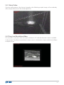
5.3.1 Noisy Video
(BVTTJBOOPJTFQBUUFSOT MJLFUIFPOFTIPXFEPOUIFGPMMPXJOHTBNQMFJNBHF XJMMDPOTJEFSBCMZ
affect the performance of the eStab algorithms.
5.3.2 Very Low Resolution Video
This situation is common when the input resolution is CIF and the electronic zoom is enabled
in the camera. The effective resolution in these cases is calculated as: (input resolution)/ eZoom
multiplier factor.
103
APPENDIX D. Setting up the Surveillance Monitor
1 Introduction
The Video Surveillance Monitor offers a set of tools to allow the user to take full advantage of the
surveillance capacity of their sensor network system. This Appendix shows how to set up the
surveillance system using the VMD (Video Motion Detection) algorithm, the Target Acquisition
algorithm, or a combination of the two.
The Video Surveillance Monitor allows the user to create specific surveillance areas on the
monitor image, letting the user set specific trigger alarms based on detected movement on the
video image.
2 Items Required
Any Nexus compliant camera or FLIR Sensors Manager’s compliant video source, e.g., video
stream, DirectX compatible video capture device (frame grabber), or file (ASF/AVI file, etc.).
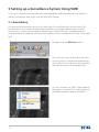
3 Setting up the Environment
This section is based on the following assumptions:
t
5IFDBNFSBTBSFDPSSFDUMZDPOGJHVSFEBOEUIFWJEFPJTEJTQMBZFEGMBXMFTTMZ
t
5IF'-*34FOTPST.BOBHFS1SP-JDFOTFJTMPBEFE XIJDIFOBCMFTUIFWJEFP
post processing functions).
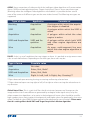
4 Important Concepts for VMD (Video Motion Detection) and Target Acquisition
VMD is the acronym for Video Motion Detection. It consists on an algorithm that is able to detect
motion inside predefined “VMD” or “VMD & Track” areas in the video channel. When there is pixel
difference detected inside any of these predefined areas, a VMD alarm is triggered.
ROI (Region of Interest): Defines the region of the video that will be analyzed by any of
the image post processing algorithms. Everything inside the ROI will be processed, whereas
everything outside of it will be ignored by the surveillance algorithms. The scroll bars of the ROI
TFDUJPODBOBEKVTUUIFTJ[FBOEUIFQPTJUJPOPGUIF30*BTXFMMBTNBLJOHJUi7JTJCMFwPSOPUPOUIF
video window. This concept is common for VMD, Target Acquisition and all the other image post
processing tools.
104
AREAS: Areas are portions of video on which the intelligent video algorithms will create motion
alarms (VMD) or entering/exiting alarms (Target Acquisition). There is also a special area type
(Blanking) where the intelligent video algorithms are disabled. It is possible to draw several
areas of the same or of different types on the same video channel. The following area types are
supported:
Type of Area
Applied to
Consists of
Blanking
Acquisition
A polygon within which the acquisition engine is disabled
VMD
VMD
A polygon within which the VMD is
active
Acquisition
Acquisition
A polygon within which the rules
engine is active
VMD and Acquisition
VMD and Acquisition
A polygon within which both VMD
and rules engine algorithms are
active
Wire
Acquisition
An open, multi-segment line over
which the rules engine algorithm is
active
RULES: A rule is a set of conditions that may trigger an alarm. It is possible to assign one or more
rules to each defined area. Depending on the area type, these rules may be:
Type of area
Possible rules
VMD
No rules
Acquisition
Enter, Exit, Both*
VMD and Acquisition
Enter, Exit, Both
Wire
Right ‡ Left, Left ‡ Right, Any Crossing**
0CKFDUEFUFDUFEVQPOFOUFSJOH MFBWJOH PSFOUFSJOHBOEMFBWJOHTFMFDUFEBSFB
0CKFDUEFUFDUFEVQPODSPTTJOHSJHIUUPMFGU MFGUUPSJHIUPSXIFODSPTTJOHUIFTFMFDUFEBSFBJO
any direction
Global Noise Filter: This is a statistical filter that discriminates between real changes on the
image and the inter-frame differences generated by analogical video signal noise, or by the
video compression algorithms, or by noise in the background. Lower values should be used for
high compression or noisy images or backgrounds, and higher values for good quality, low noise
video. The default value (0.03) has been proved to be adequate for most situations. Please note
that this setting affects both VMD and Target Acquisition’s Motion algorithm.
105
5 Setting up a Surveillance System Using VMD
To set up a surveillance system that takes advantage of the VMD algorithm, the user needs to
define a surveillance area; for this use the “Area Edit” function.
5.1 Area Edition
The area edit function allows the user to create specific surveillance areas on the screen. This
function allows the creation of zone where movement can trigger a preset alarm, as could
be the case in a zone close to a gate, or along a fence. The area drawn is a polygon and can
accommodate any shape the user wants. For simplicity, in this example we are using a four-sided
box.
To begin, click the Edit Area button.
The cursor has now turned into a pen. Position the cursor in the desired beginning location, left click to select the area type and
place the first point in the polygon area.
For this example the VMD (Video Motion
Detection) is selected. For a description of
the different options, please see below.
106
Move the cursor to the next point in the
area and click the left mouse button once.
A red line appears, marking the first side of
the polygon.
Move the cursor to the next point and single
click; because the points are now defined a
triangle appears.
Move the cursor to the last point, in this case
the lower left corner of the rectangle shape
demonstrated in this example; in this case,
double click to complete the area drawing.
When the user double-clicks to terminate
the drawing process, the polygon is complete and an area identifier appears. The
first area created is marked with a “0”. Subsequent areas that are created are marked
with “1”, “2”, etc.
To delete an area the Surveillance Monitor window will need to be accessed. To do so, click View
and select the “Surveillance Monitor” option:
107
The Surveillance Monitor window is displayed.
1.
2.
3.
4.
5.
108
Click on the top icon on the left-hand side (the pen icon) to list the existing areas.
Make sure the Show Areas box is checked).
To delete “0 VMD”, select it
Click the Remove button to remove “0 VMD”.
The user can also enable the Create Area checkbox, which turns on the Edit Area icon
(pen). This is an alternative way to creating an area from within the Surveillance Monitor
window, instead of simply clicking on the Edit Area icon on the Toolbar.
For detailed information on setting up the different parameters for VMD, please refer to section 4
above.
NOTE: Up to 10 areas can be drawn on the displayed video window. Each area can be created
using up to 20 vertexes (points in the polygon).
109
5.2 Alarm Monitoring
If motion is detected within a VMD area, an alarm is triggered. An FSM notification is displayed on
the lower right corner of the screen.
Clicking on the Alarm Monitor bar displays a list of alarms and associated information for each
alarm:
The Alarm Monitor has three buttons:
t
t
t
110
Stop: stops logging alarm notifications. Click Start to star again.
Clear: clears list of logged alarm notifications.
Filters: allows the user to restrict alarms generated by a specific server. Alarms can be
filtered by server and by string (only the alarms containing the typed string will be listed).
Alarms can be managed using the Alarms Manager. For more information see section 5.21
Alarms Manager.
5.3 Fine Tuning VMD Parameters
Sometimes an alarm is triggered by moving elements that are of no interest. Typical examples
BSFUIFNPWJOHMFBWFTPGUSFFT PSUIFUSBGGJDPOBEJTUBOUSPBE*UJTQPTTJCMFUPBEKVTUUIFBMBSN
trigger sensitive in order to ignore these false alarms. To achieve this, some parameters like
(MPCBM/PJTF'JMUFS 4FOTJUJWJUZBOE4J[FDBOCFBEKVTUFE
6 Target Acquisition
This is a group of algorithms intended to detect mobile or static targets and tag them with a
unique ID. There are three algorithms for Acquisition:
Thermal: Detects and identifies fixed or moving targets marking them with a unique ID tag on
video from IR cameras using threshold criteria to detect white (hot) or black (cold) spots.
Motion: Detects and identifies moving targets marking them with a unique ID tag on all kind of
video using motion criteria.
Slow Motion: Detects and identifies moving targets marking them with a unique ID tag on all
kind of videos using slow motion criteria (frequently used in maritime environments where the
movements of the targets are very slow, like in the case of sailboats in the distance).
111
6.1 Setting up a Surveillance System Using the Target Acquisition
algorithms
Depending on the source of the video and the motion parameters of targets to be detected,
the most appropriate algorithm should be selected. Below is a typical procedure for setting up a
surveillance system based on the Motion Target Acquisition algorithm.
Open the Surveillance Monitor and set the ROI. Make sure to enable the Show ROI check box to
display the ROI on screen:
112
Select the appropriate Target Acquisition algorithm depending on the needs and sensor type
(Thermal, Motion, Slow Motion). For this example, the Motion Target algorithm is selected. Enable
also the Show Processing box:
113
An image similar to this should now display on the video window:
Notice how the algorithm is processing the movements produced inside the ROI. If the
algorithm is classifying as motion what is actually background noise (moving leaves) some fine
UVOJOHDBOCFEPOFCZBEKVTUJOHUIFi(MPCBM/PJTF'JMUFSwTMJEFS
114
6.2 Global Noise Filter Slider
The Global Noise FilterTMJEFSTIPVMECFBEKVTUFEUPEJTDSJNJOBUFOPJTFCFUXFFOCBDLHSPVOE
BOEUIFBDUVBMUBSHFUT.PSFJOGPSNBUJPOPOUIFi(MPCBM/PJTF'JMUFSwDBOCFGPVOEBUTFDUJPO
i*NQPSUBOU$PODFQUTGPS7.%w"DPSSFDUBEKVTUNFOUPGUIJTQBSBNFUFSXJMMSFOEFSSFTVMUTTJNJMBS
to the picture below:
Now, all the movements of the leaves in the trees area have disappeared in the ROI because the
5BSHFU"DRVJTJUJPOBMHPSJUINJTSFKFDUJOHUIFNBTTUBUJTUJDBMOPJTF
115
6.3 Min and Max Size
These two values are related to the minimum and maximum size range (in a percentage scheme
relative to the total size in pixels of the video image) for the target.
Once these values are set, the Show Processing checkbox may be unchecked to see the video
normally with the Target Acquisition algorithm running on it.
At this stage there are a lot of targets detected (red boxes with an id number) corresponding
UPJOEJWJEVBMQBSUTPGUIFCPEZPGUIFNPWJOHTVCKFDU"EKVTUNFOUTDBOCFEPOFUPVOJGZ
fragmented targets into one single target (trunk, legs and shadow from a person walking across
a parking lot).
116
6.4 Clustering Target Fragments into a Single Target
The “Average Size” value is related to the size of the target (width and height).
The “Depth Effect” value is related to the size and position of the target when
this target is located far in the image perspective (background).
As soon as these values are changed, two red squares appear on the video channel window. The
one located on the lower left corner of the video corresponds to the “Avg. Size” parameter and
the one located above corresponds to the “Depth Eff.” parameter. The Avg. Size slider should be
set to match the target size (including shadow) on the foreground.
Target clustering in the background is managed with the “Size” and “Pos” sliders in the Depth
Effect section. The “Pos” slider selects the position (depth) at which the farthest target may be
grouped.
The size sliders set the size percentage of the background target associated with the setting
already fixed to the foreground. The rest of values in between foreground and background are
KVTUJOUFSQPMBUFE
117
"GUFSBEKVTUJOHUIFTFUXPQBSBNFUFSTUIF"DRVJTJUJPOBMHPSJUINJTBCMFUPQSPDFTTFBDIUBSHFUBT
BXIPMFPCKFDU JODMVEJOHUIFTIBEPXPGUIFQFSTPO BTTIPXOJOUIFOFYUJNBHF
118
6.5 Acquisition and Drop Times
The “Acquisition” value relates to the time (in seconds) elapsed between when a target appears
in the ROI and when the algorithm marks it as a target. The “Drop” value, represents the time
(in seconds) elapsed between when a target disappears from the ROI to the moment when the
BMHPSJUINTUPQTTFBSDIJOHGPSUIFMPTUUBSHFUVTJOHQSFEJDUJWFUSBKFDUPSZBOBMZTJTNFUIPET
The “Max. Distance” value refers to the statistical distance between targets when predicting
motion. This parameter must be set to prevent the algorithm from merging two close moving
targets into a single target. Lower values should be set when moving targets are expected to get
very close.
119
7 Profiles
Profiles are used to save all the configuration parameters as well as the ROI, all the defined areas,
and all the established rules for a given scene or environmental/lighting conditions.
Settings are saved for both VMD and Target Acquisition algorithms. To create a profile, right click
on the video channel window and select “Save Profile”:
120
(JWFBOBNFUPUIFQSPGJMFBOEDMJDLSave.
To load a profile, right –click on the video window and select “Load Profile.” All the settings
loaded in the saved profile are applied.
121
8 Additional Target Acquisition algorithms
Thermal, Motion and Slow Motion Algorithms
The following additional settings help fine tune the thermal, motion and slow motion algorithms
and are common to all three. In this example the Thermal algorithm is selected:
Temperature and polarity: The temperature value refers to the thermal intensity of the targets
intended for detection. Higher values of this parameter indicate higher thermal intensity of a
target. The polarity (White hot or Black hot) refers to the polarity set in the camera configuration.
122
Sensitivity: Higher values indicate a more sensitive algorithm, thus creating more possible
targets.
Speed: The Speed value indicates the expected speed of the targets to be acquired. Higher
value indicates the algorithm to look for faster tracks.
123
9 Summary of VMD and Target Acquisition Settings
124
APPENDIX E. Shortcuts
SPLASHSCREEN
MAIN WINDOW
ALL WINDOWS
CURSOR MODES (Map,
Video Wall and Panorama
windows
Ctrl + F Ignore profile on load
Ctrl + M Toggle main menu
Ctrl + T Toggle title bar
A Arrow cursor mode (no action)
H Hand cursor mode (pan)
R Reticule cursor mode (aim)
Z/Shift + Z Zoom in/out cursor mode (continuous zoom
on mouse down, stop on mouse up for the
video)
VIDEO WALL
Ctrl + F Mouse double-click: full screen
Esc Exit full screen
MAP
Mouse Wheel Zoom in/zoom out
Ctrl + mouse Pan horizontal
wheel
Shift + mouse Pan vertically
wheel
Alt+Mouse Wheel Rotate map right
or Ctrl+R
Alt+Mouse Wheel Rotate map left
or Ctrl+Shift+R
Ctrl+N Reset rotation
B/ Shift+B Map opacity
PANORAMA
Mouse double Aim (regardless of the cursor mode)
click
125
GLOSSARY
Acquisition
Function carried out by a group of algorithms intended to detect mobile or static targets and tag them with a unique ID.
"($
"VUPNBUJD(BJO$POUSPM "($ BMMPXTGPSBDMFBSWJEFPPVUQVU despite variations in the signal obtained by the sensor. Weaker
signals receive more gain; stronger signals receive less gain or
none at all, depending on parameters set.
Blanking
An area on the video image within which the acquisition engine is disabled. Useful when it is necessary to exclude certain
areas in the image from triggering false alarms.
BMP
The BMP file format, sometimes called bitmap, is an image file
format used to store bitmap digital images.
CIF
CIF (Common Intermediate Format), also known as FCIF (Full
Common Intermediate Format), is a format used to standardize the horizontal and vertical resolutions in pixels of YCbCr
sequences in video signals.
DLTV
Daylight TV. It refers to the daylight, or standard video camera
sensor.
eStab
Electronic Stabilization. This function utilizes an algorithm to
stabilize shaky images caused by movement or vibration of the
sensor, as might be the case when the camera is mounted on a
high pole or a vehicle.
FOV
Horizontal Field of View of the camera.
FPA
Focal-plane array is an image sensing device consisting of an
array (typically rectangular) of light-sensing pixels at the focal
plane of a lens.
FPS
Frames per Second. This relates to the frame rate, or frame frequency, which is the measurement of the frequency (rate) at
which an imaging device produces unique consecutive images
called frames. Frame rate is most often expressed in frames per
second (FPS) and in progressive-scan monitors as hertz (Hz).
FSM
FLIR Sensors Manager.
(FPMPDBUJPO
(FPMPDBUJPOJTUIFJEFOUJmDBUJPOPGUIFSFBMXPSMEHFPHSBQIJD
MPDBUJPO -BU-POH PGBHJWFOPCKFDU
126
(*4
"HFPHSBQIJDJOGPSNBUJPOTZTUFN (*4 DBQUVSFT TUPSFT BOBMZ[FT NBOBHFT BOEQSFTFOUTEBUBUIBUJTMJOLFEUPMPDBUJPO(*4
refers to any geographic information systems which includes
mapping software and its application with remote sensing,
land surveying, aerial photography, mathematics, photogramNFUSZ HFPHSBQIZ BOEUPPMTUIBUDBOCFJNQMFNFOUFEXJUI(*4
software.
(14
5IF(MPCBM1PTJUJPOJOH4ZTUFN (14 JTB64TQBDFCBTFEHMPbal navigation satellite system that provides reliable positioning,
OBWJHBUJPO BOEUJNJOHTFSWJDFTUPXPSMEXJEFVTFST(14TBUFMMJUFTCSPBEDBTUTJHOBMTGSPNTQBDFUIBUBSFVTFECZ(14SFDFJWFST
to provide three-dimensional location (latitude, longitude, and
altitude) plus the time.
I/O
Input/Output. Typically refers to an I/O sensor that gets input
signals and allows enabling devices connected to its outputs.
IR
Infrared. It refers to the infrared sensor.
+1(
4IPSUGPS+PJOU1IPUPHSBQIJD&YQFSUT(SPVQ+1(JTPOFPGUIF
image file formats supported by FSM.
Leveling
Calibration process done when a server is not installed over a
horizontal surface.
Longitudinal Error
One of the parameters of the leveling. It is the sensor rotation in
the longitudinal (front-to-rear) axis.
LRF
Laser Rangefinder. A laser rangefinder is a device which uses a
MBTFSCFBNUPEFUFSNJOFUIFEJTUBODFUPBSFnFDUJWFPCKFDU
MP3
.1&("VEJP-BZFS .1 JTBEJHJUBMBVEJPFODPEJOHGPSNBU
using a form of data compression. It is a common audio format
for consumer audio storage, as well as a de facto standard of digital audio compression for the transfer and playback of music
on digital audio players.
.1&(
.PWJOH1JDUVSF&YQFSUT(SPVQUIFUFSNSFGFSTUPUIFGBNJMZPG
digital video compression standards and file formats commonMZVTFE.1&(BMHPSJUINTDPNQSFTTEBUBUPGPSNTNBMMCJUTUIBU
can be easily transmitted and then decompressed.
127
NDVR
Network Digital Video Recorder is a fail-safe storage solution
that offers continuous recording of up to 25 simultaneous
.1&( OFUXPSL WJEFP TUSFBNT GSPN /FYVT TFOTPST EJSFDUMZ UP
digital indexed storage.
NMEA
Combined electrical and data specification for communication
between electronic devices such as echo sounder, sonar, anemometer (wind speed and direction), gyrocompass, autopilot,
(14SFDFJWFSTBOENBOZPUIFSUZQFTPGJOTUSVNFOUT*UIBTCFFO
defined by, and is controlled by, the U.S.-based National Marine
Electronics Association (NMEA).
NUC
Non-Uniformity Calibration. FPA Calibration process in IR sensors.
OSD
0O 4DSFFO %JTQMBZ (SBQIJD JOGPSNBUJPO UIBU DBO CF PWFSMBJE
over the video image to provide timestamp, sensor name, sensor geo-location, azimuth/elevation, field of view, and head-up
display.
PLAT
(Platform) Pan and Tilt. A device that allows changing the orientation of the sensor.
POV
Point of View. In Joysticks, it refers to a hat-like device on top of
UIFKPZTUJDLUIBUSFTFNCMFTBTNBMMKPZTUJDLXJUIBmYFEOVNCFS
of positions.
PT
Pan and Tilt also called PLAT.
ROI
Region of Interest. Refers to a user-selectable area of the image
that requires particular attention. The ROI also creates an area
where video post-processing algorithms and image filters are
applied.
SDK
The Software Developers Kit (SDK) is a tool that helps systems
integrators to deploy FLIR Systems thermal imaging cameras in
large, existing or new, security networks. The SDK is designed
to accelerate any application programming with FLIR Systems
thermal imaging cameras. The SDK toolkit allows for “plug &
play” installation of FLIR Systems thermal imaging cameras in
TCP/IP infrastructures.
Transversal error
One of the parameters of the leveling. It is the sensor rotation in
the transversal (left-to-right) axis.
128
VMD
Video Motion Detection. It consists on an algorithm that is able
to detect motion inside predefined “VMD” or “VMD & Track”
areas in the video channel. When motion is detected inside any
of these predefined areas, a VMD alarm is triggered.
VPP
Video Post Processing. The post-processing module allows managing the detection algorithms, the image filters, and the electronic stabilization.
WAV
WAV (or WAVE), short for Waveform audio format, also known
as Audio for Windows, is a Microsoft and IBM audio file format
standard for storing audio files on PCs.
Wire
An open, multi-segment line over which the rules engine algorithm is active. Can be set like a video “trip wire” drawn across an
image to trip alarms.
129
LEGAL NOTE
Excel, Windows XP and Windows Vista are registered trademarks of Microsoft Corporation in the United States and other countries. Nvidia™ and ATI™ are registered
trademarks of their respective corporations in the United States and other countries.
130
131