1
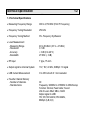
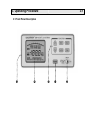
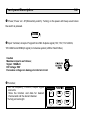
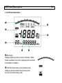
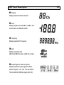
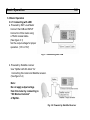
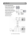
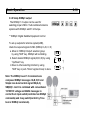
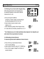
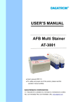
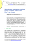
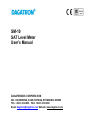
SM-10 SAT Level Meter User’s Manual DAGATRONICS CORPORATION 263-1 DUCKIDONG, ILSAN, KOYANG, KYUNGKIDO, KOREA TEL: +82-31-916-8005 FAX: +82-31-916-8080 Email: [email protected] Website: www.dagatron.com Α Operating Safety Precautions g Introduction Thank you for purchasing our product. Electronic measuring instruments produced by us are high technology products made under strict quality control. We guarantee their exceptional precision and utmost reliability. To ensure safe operation of this instrument, be sure to follow the warning and precautions provided as bellow. g Warning Note • Do not use this product or equipment connected to it in an explosive, ignitable, or flammable atmosphere, as this will result in the risk of explosion. • Do not connect this product to a piece of equipment or cable having a voltage with respect to ground on its chassis, as such connection can result in the risk of electrical shock. • Use a proper Battery charger for charging internal rechargeable battery pack. g Caution • Do not remove the case cover, as this can risk failures or loss of performance. • Do not allow water to enter the product. This product is not waterproof. • If condensation forms on this product due to a sudden change in temperature, use this product only after allowing it to dry sufficiently. 2 Table of Contents 1. Product Description 1.1 Introduction 1.2 Features 1.3 Technical Specification 2. Installation 2.1 Initial Inspection 2.2 Charging and Discharging Instruction 2.3 Cooling and Ventilation 3. Operating Procedure 3.1 Function Panel Description 3.2 LCD Panel Description 3.3 Basic Operation 3.3.1 Connecting LNB 3.3.2 Setup for Multi-Site Viewing 3.3.3 Change of Frequency to measure 3.3.4 Setup Function of measurements 3.3.5 Setup Output for Antenna system 3.3.6 Setup DiSEqC output 3.3.7 Unit Selection 3.3.8 Change of Channel Number 3.3.9 Storing of new channel with changed settings 3.3.10 Recalling of stored channel 3.3.11 Indicating the level of internal battery 1-1 1-1 1-1 1-2 2-1 2-1 2-1 2-1 3-1 3-1 3-4 3-6 3-6 3-7 3-8 3-8 3-9 3-10 3-11 3-11 3-12 3-12 3-13 2 Table of Contents 3.4 Level Measurement procedure 3.4.1 Measure with stored channel and conditions 3.4.2 Measure by setting conditions 3.4.3 Measurement of LNB Current 3.5 Additional Functions 3.5.1 Peak Holder 3.5.2 Acoustic signal strength monitoring 3.5.3 Last channel and condition memory 3.5.4 Back lighting for LCD Display 3.5.5 Auto Power off 4. Maintenance 4-1. Adjustment and Calibration 4-2. Battery charging 4-3. Cleaning and Decontamination 3-13 3-13 3-13 3-14 3-15 3-15 3-15 3-15 3-15 3-15 4-1 4-1 4-1 4-3 1. Product Description 1-1 1.1 Introduction This professional SAT Level Meter has been designed for the installation and maintenance of analog and digital satellite TV system. The inside circuitry and mechanical design has been carefully developed in order to obtain very light, slim typed field strength meter. To allow the installer to work in the best conditions, it is also offering built-in LNB powering and hang-on-the neck type carrying case. The LCD display with Back-light is shown several kinds of information such as Frequency, Measuring level, Function, units and bar graph. The compact metal cabinet will be a right choice for heavy-duty field use. It is a real instrument to measure, verify and optimize satellite TV systems at any stage of installation. 1.2 Features • Handheld, portable SATELLITE IF SIGNAL STRENGTH METER • PLL tuning control for Frequency Selection (From 900MHz to 2,150MHz) • 13V, 18V, 22kHz and DiSEqCTM1.0 leveled signal output for selecting LNB • LNB Current measurement (Up to 250mA) • Built in Rechargeable Battery pack for powering LNB • Auto power off • 99 Favorite Channel memory • Peak holder function for detecting Max. Input level Display • Buzzer for Acoustic signal strength monitoring • Multi LCD display with Back light • Last condition Store & memory • Key Entry control • Deluxe HANG-ON-NECK type CARRYING CASE for hand-free use Technical Specification 1-2 1.3 Technical Specifications • Measuring Frequency Range 900 to 2,150 MHz (First IF Frequency) • Frequency Tuning Resolution 250 kHz • Frequency Tuning Method PLL Frequency Synthesizer • Level Measurement - Measuring Range - Resolution - Accuracy - Bandwidth 40 to 80 dBuV (-67 to –27 dBm) 0.1 dB ± 3 dB (0 to 40°C) 27 MHz (- 3 dB) • RF Input F type, 75 ohm • Output signal to Antenna System 13V, 18V, 22 kHz, DiSEqC 1.0 signal • LNB Current Measurement 0 to 250 mA with 0.1 mA resolution • Favorite Channel Memory - Number of channels - Storable Items 99 Frequency: 900MHz to 2150MHz in 250kHz step Function: Normal, Peak holder, Sound Unit of Level: dBuV, dBm, mADC Output signal to LNB: 13V,18V,13V+22kHz,18V+22kHz, DiSEqC (A,B,C,D) Technical Specification 1-3 • Auto power off Preset to 10 Minutes • Internal Power - Capacity of Rechargeable Battery - Battery Life 12V/1200mA AH (Metal Hydride) 2 HRS at 250mA LNB Load • Power requirement for charging DC12V 500mA (Charge & Adaptor) • Display Multi LCD Display with Back-light Frequency, Channel, Level, dBuV, dBm, mADC, Function, Battery level, Output Signal for Antenna, Bar Graph • Environmental Conditions - Operating Temperature Range - Operating Humidity Range - Storage Temperature Range 0 to 40 °C 30 to 85 % RH -10 to 50 °C • Dimensions and Weight 180(W) x 75(H) x 150(D) mm Approx. 1.5 kg • Supplied Standard Accessories Battery Charger (12V 500mA) 1 Carrying Case 1 User’s Manual 1 2. Installation 2-1 2.1 Initial Inspection This instrument was carefully inspected both mechanically and electrically before shipment. It should be physically free of damage. To confirm this, the instrument should be inspected for physical damage in transit. Also, check for supplied accessories. 2.2 Charging and Discharging Instruction a. New batteries are supplied in an uncharged state. To ensure the maximum battery performance, a new battery (or long time not-used-battery) should be charged for at least 10 hours before use. b. A new battery will require several full-charge/discharge cycles in order to achieve its optimum performance. After 1st full charge, use battery until full discharge level, and 2nd charge to full level, Repeat this cycle several times before starting the main use of battery. c. Best battery performance will be achieved when you regularly charge and discharge batteries. d. If left unused, a fully charged battery will discharge itself in approximately one month. ** Please refer to “4.2 Battery Charging, page 4-1“ for the details of charging method. 2.3 Cooling and Ventilation No special cooling and ventilation is required. However, the instrument should be operated where the ambient temperature is maintained. 3. Operating Procedure 3-1 3.1 Front Panel Description • • Ž Œ • Front panel Description 3-2 Œ Power; Power on / off (Momentary switch). Turning on the power with beep sound when the switch is pressed. ? • Input Terminal; Accepts IF signal from LNB. Outputs signal (13V, 18V, 13V+22kHz, 18V+22kHz and DiSEqC signal) to Antenna system (LNB or Switch Box). Caution Maximum input is as follows; Signal: 100dBuV DC Voltage: 50V Excessive voltage can damage to internal circuit. Ž Function; - Set the frequency, Function, Output Signal and units. - Store the function and data for desired channel and call the stored channel. - Turning on back-light. Front Panel Description 3-3 Use to select the function of Up/Down key. (Frequency, Channel, Function, Output signal, unit) Use to store the desired conditions of each channel(push two times) (Frequency, Function, Audio Sub-carrier, measuring unit) Use to change the measuring conditions in selected channel momently (push one time) Use to call stored channel Use to turn on and off back light (Up) (Down) key. Use to change the value in selected function by • Change of Frequency (From 900MHz to 2,150MHz in 250kHz step) • Change of Channel (CH 01,02,… up to 99) • Change of function (Normal, Peak holder, Sound) • Change of Output signal (13V,18V,13V+22kHz,18V+22kHz,DiSEqC) • Change of measuring unit (dBuV, dBm, mADC) • LCD Display; Displays measurement level and various information. • DC INPUT for charging internal battery pack; Accepts external DC power from AC adaptor and Cigar socket of Car for charging internal battery pack. When the AC Adaptor is used for charging, DC 12V 500mA is required. The input power jack could be accepting with center plus (+). LCD Panel Description 3-4 3.2 LCD Panel Description Œ { • z Ž • • Œ Bar-Graph; Displays signal level. Minor division indicates 1 dBuV. Same quantities of bar will be displayed with input level from 40dBuV to 80dBuV. • Function (Peak holder, Sound, Battery level) Displays selected function (Peak, Sound) and the level of internal battery pack. LCD Panel Description Ž Channel Displays selected channel number. • Level Displays signal level with dBuV or dBm, and current value to LNB with mADC. • Frequency Displays selected IF frequency. z Units Displays selected units (dBuV and dBm for level, mADC for current) { Output Signal to Antenna System Displays selected output signal to LNB or Antenna system. 13V, 18V, 13V with 22kHz, 18V with 22kHz, DiSEqC signal (A,B,C,D) 3-5 Basic Operation 3-6 3.3 Basic Operation 3.3.1 Connecting with LNB a. Powered by SAT Level Meter Connect the LNB and INPUT Connector of this meter using a 75ohm coaxial cable. (See figure 3-1) Set the output voltage for proper operation. (13V or 18V) Fig. 3-1 Connecting with LNB b. Powered by Satellite receiver Use “Splitter with DC-block” for Connecting this meter and Satellite receiver. (See figure 3-2) Note : Do not apply output voltage from this meter by connecting to “DC Blocked terminal” of Splitter. Fig. 3-2 Powered by Satellite Receiver Basic Operation 3-7 3.3.2 Setup for Multi-Site Viewing Figure 3-3 is shown a set-up example for two LNB (or antenna) system. When connect this meter to the outlet (or Output of switch Box), connect through “DC Block” to cut the OUTPUT Signal form this meter. Refer to Section 3.3.1 “Connecting with LNB” for connecting this meter to the LNB(or Antenna system). Fig. 3-3 Setup for Multi-Site viewing Basic Operation 3-8 3.3.3 Change of Frequency to measure The frequency can be changed in initial status of operation after selecting Channel. a. Select desired frequency to measure level by using “Up”,“Down” key. (900MHz – 2,150MHz with 250kHz step) ** The frequency change is speed up by pressing “Up/Down” key for fast change of frequency. b. Move to other selecting function by using “Shift” key or push “Store” key(two times) to store. ? ? 3.3.4 Setup Function of measurements The measuring function (Normal, Peak Holder, Sound monitoring) can be selected. a. Move to “Function” selection group by using “Shift” key. Function group will be blinking. ? Basic Operation b. Select desired function by using “Up/Down” key. - Sound: Acoustic signal strength monitoring - Peak Holder: Displayed Measuring level is changed when new measuring level is higher than previous measured value. - Normal: Displayed Measuring level from input terminal. (Blank of Function display) c. Move to other selecting function by using “Shift” key or push “Store” key(two times) to store. 3-9 ? ? 3.3.5 Setup Output for Antenna system To set up outputs for antenna system(LNB), check the required signal of LNB. (13V, 18V, 13V+22kHz, 18V+22kHz) a. Move to “Output” selection group by using “Shift” key. Outputs group will be blinking. ? b. Select desired output signal by using “Up” “Down” key. ? c. Move to other selecting function by using “Shift” key or push “Store” key(two times) to store. ? Basic Operation 3-10 3.3.6 Setup DiSEqC output The DiSEqC 1.0 output can be used for selecting proper LNB in “multi-combined antenna systems with DiSEqC switch” in Europe. ** DiSEqC: Digital Satellite Equipment Control To set up outputs for antenna system(LNB), check the required signal of LNB. (DiSEqC A, B, C, D) a. Move to “DiSEqC Output” selection group by using “Shift” key. DiSEqC will be blinking. b. Select desired DiSEqC signal(A,B,C,D) by using “Up/Down” key. c. Move to other selecting function by using “Shift” key or push “Store” key(two times) to store. Note: The DiSEqC Level 1.0 commands are composed DiSEqC messages <A,B,C,D> and Simple tone burst control signal<SA(A,C), SB(B,D)>. And it is combined with conventional 13/18V DC voltage and 22kHz messages to control the 4 input switch(controlled via DiSEqC commands) and 2 way switch(control by Tone bust or DiSEqC commands). ? ? ? Basic Operation 3-11 3.3.7 Unit Selection The units of level(dBuV and dBm) and unit of current can be selected for using desired unit. a. Move to “Unit” selection group by using “Shift” key. Unit group will be blinking. ? b. Select desired unit by using “Up” “Down” key. (dBm, dBuV, mADC) ? c. Move to other selecting function by using “Shift” key. ? ** When the “mADC” is selected, the current supplying to LNB is displayed. 3.3.8 Change of Channel Number a. Move to “Ch” selection by using “Shift” key. “Ch” will be blinking. ? b. Select desired channel by using “Up” “Down” key. (Ch 01…99) ? c. Move to other selecting function by using “Shift” key or push “Store” key(two times) to store. ? Basic Operation 3-12 3.3.9 Storing of new channel with changed setting After setting each function and measuring level, the selected conditions can be stored in desired Channel from 01 to 99. a. Set up all required conditions (Frequency, Function, Output, unit) according to the set-up procedures from 3.3.3 to 3.3.6. b. Select desired channel number to store. (Refer to 3.3.7) c. Store Channel by pushing “Store” Key(two times). d. To store other new channels, proceed from “a” to “c”. ? ** All of channels are set to initial conditions before shipment. So it should be set and stored for the requirements of customer. 3.3.10 Recalling of stored Channel To measure input level with conditions of stored channel, a. Press “Call” key to select desired channel. The “Ch” will be blinking. b. Select desired channel by using “UP”, “DOWN” key. c. Press “Call” key again to apply the conditions of selected channel. ? ? ? Level Measurement Procedure 3-13 3.3.11 Indicating the level of internal battery ( ) The level of internal battery is displayed on “Battery indicator”. Refer to following table for the status of battery. Battery sign of Indicator Time for use Three bars of indicator Approx. 2 hrs. Two bars of indicator Approx. 1 hrs. One bar of indicator Approx. 30 min. Blinking Indicator Need to charge Auto Power off with beep sound 3.4 Level Measurement Procedure There are two ways to measure input level. 3.4.1 Measure with stored channel and conditions a. Select desired channel by using “Call”, “Up/Down, Call” key. b. Connect the cable to Input terminal. c. Read “The value of input level” on Display. ? 3.4.2 Measure by setting the conditions a. Select desired frequency to measure by using “Up/Down” Key. Refer to “3.3.3 Change of Frequency”. ? b. Select the desired conditions(Function, Output, Unit) by using “Shift”, “Up/Down” Key. Refer to “3.3.4 to 3.3.6”. c. Read “The value of input level” on Display. d. Return to previous measuring condition by pushing “Call” key(two times). Measurement of LNB Current 3-14 3.4.3 Measurement of LNB Current The value of current to LNB can be measured as follows; a. Select Unit group by using “Shift” key. ? b. Select “mADC” by using “Up, Down” Key. ? c. Read “The value of current” on Display. d. Return to previous measuring condition by pushing “Call” key (two times). NOTE: “Store” Key operation The “Store” key can be used for storing the selected information of channel (Frequency, Function, Audio sub-carrier, Unit) and also it can be used to hold changed measuring conditions of selected channel momently without storing. - To store selected information: Push “Store” two times This operation can be used to set-up or change measuring conditions of each channel. - To hold selected condition momently: Push “Store” one time This operation can be used to change measuring methods and units momently during measuring without changing stored conditions. Return to stored measuring condition by pushing “Call” key two times. Additional Functions 3-15 3.5 Additional Functions 3.5.1 Peak Holder ( ) This meter has “Peak Holder function” to support easy installation of antenna system by detecting highest input level. The displayed measuring level is changed when new measuring level is higher than previous measured value. To set this function, see to 3.3.4. 3.5.2 Acoustic signal strength monitoring ( ) This meter has acoustic signal strength monitoring function to support easy installation of antenna system by hearing the strength of input signal. The beef sound with 1kHz is varied according to the value of input level. To set this function, see to 3.3.4. 3.5.3 Last channel and conditions memory When the meter turns off, the meter can memory last channel and conditions for supporting same conditions with previous measuring. When the power is turning on by pushing “Power” key, the previous channel and conditions are applied again. 3.5.4 Back Light for LCD display To read the display in dark area, the back light is turning on by pushing “Lamp” button. To turns off back light, push “Lamp” button again. 3.5.5 Auto Power off When the voltage of internal battery pack is less than proper voltage and the operation of meter is stopped more than 10 minutes, the power is turning off automatically for saving internal power. When the power is turning on by pushing “Power” key, the previous channel and conditions are applied again. 4. Maintenance 4-1 4.1 Adjustment and Calibration It is recommendable to regularly adjust and calibrate this meter. Qualified and authorized personnel only should execute performance and procedures. When the calibration or service is required, contact with our local agent. 4.2 Battery charging CAUTION and NOTE that the battery should be fully charged after first opening the box. The first time charging is important. Always keep the battery level fully charged before and after use. For charging, we recommend you following ways. 4.2.1 Charging by AC adaptor (Figure 4-1) The 12V 500mA DC is recommendable for charging. The input power jack could be accepting with center plus (+). Connect adaptor as follows. Charging time is subject to the condition of battery pack. Fig. 4-1 Charging by AC adaptor Battery Charging 4-2 4.2.2 Charging by power from Cigar-Socket of car (Figure 4-2) The internal battery of this meter can be charged form Cigar-Socket of car. The out voltage of Cigar socket should be higher than 12VDC. Connect the power from Cigar socket as follows. Charging time is subject to the condition of battery pack. Fig 4-2 Charging by power from Cigar-Socket of car NOTE: Charge/Discharge instruction l l l For a new or longtime-not-used battery, you should do the complete charge to Max. and exhaust (use) completely. Do not leave the battery connected to a charger more than one day. Battery is gradually wearing out. If the operation time is noticeably shorter than normal, it is time to buy a new battery. Cleaning and Decontamination 4-3 4.3 Cleaning and Decontamination The instrument can be cleaned with a soft clean cloth to remove any oil, grease or grime. Never use liquid solvents or detergents. If the instrument gets wet for any reason, dry the instrument using low-pressure clean air at less than 25 PSI. Use care and caution around the window cover areas where water or air could enter into the instrument while drying.