1
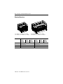
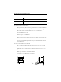
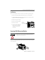
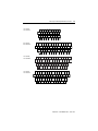
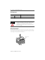
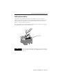
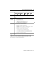
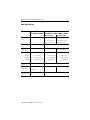
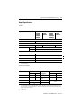
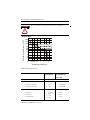
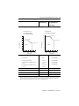
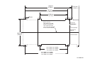
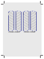
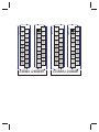
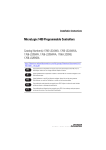
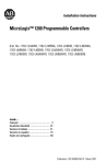
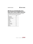
Installation Instructions
MicroLogix 1200 Programmable Controllers
(Cat. No. 1762-L24AWA, 1762-L24BWA, 1762-L24BXB, 1762-L40AWA,
1762-L40BWA, 1762-L40BXB, 1762-L24AWAR, 1762-L24BWAR,
1762-L24BXBR, 1762-L40AWAR, 1762-L40BWAR, 1762-L40BXBR)
Inside . . .
Important User Information ................................................................................. 2
For More Information ........................................................................................... 3
Overview .............................................................................................................. 4
Controller Description .......................................................................................... 5
Hazardous Location Considerations .................................................................... 6
Mounting the Controller ...................................................................................... 9
Connecting 1762 I/O Expansion Modules ......................................................... 13
Wiring the Controller ......................................................................................... 14
Specifications .................................................................................................... 20
2
MicroLogix 1200 Programmable Controllers
Important User Information
Solid state equipment has operational characteristics differing from those of electromechanical equipment.
Safety Guidelines for the Application, Installation and Maintenance of Solid State Controls (Publication
SGI-1.1 available from your local Rockwell Automation sales office or online at
http://www.ab.com/manuals/gi) describes some important differences between solid state equipment and
hard-wired electromechanical devices. Because of this difference, and also because of the wide variety of
uses for solid state equipment, all persons responsible for applying this equipment must satisfy themselves
that each intended application of this equipment is acceptable.
In no event will Rockwell Automation, Inc. be responsible or liable for indirect or consequential damages
resulting from the use or application of this equipment.
The examples and diagrams in this manual are included solely for illustrative purposes. Because of the many
variables and requirements associated with any particular installation, Rockwell Automation, Inc. cannot
assume responsibility or liability for actual use based on the examples and diagrams.
No patent liability is assumed by Rockwell Automation, Inc. with respect to use of information, circuits,
equipment, or software described in this manual.
Reproduction of the contents of this manual, in whole or in part, without written permission of Rockwell
Automation, Inc. is prohibited.
Throughout this manual we use notes to make you aware of safety considerations.
WARNING
Identifies information about practices or circumstances that can cause an explosion in a
hazardous environment, which may lead to personal injury or death, property damage,
or economic loss.
IMPORTANT
Identifies information that is critical for successful application and understanding of the
product.
ATTENTION
Identifies information about practices or circumstances that can lead to personal injury
or death, property damage, or economic loss. Attentions help you:
• identify a hazard
• avoid a hazard
• recognize the consequence
SHOCK HAZARD
BURN HAZARD
Labels may be located on or inside the drive to alert people that dangerous voltage may
be present.
Labels may be located on or inside the drive to alert people that surfaces may be
dangerous temperatures.
Publication 1762-IN006D-EN-P - June 2015
MicroLogix 1200 Programmable Controllers
3
For More Information
Related Publications
For
Refer to this Document
Pub. No.
A more detailed description of how to
install and use your MicroLogix 1200
programmable controller and expansion
I/O system.
MicroLogix™ 1200 Programmable
Controllers User Manual
1762-UM001
A reference manual that contains data
and function files, instruction set, and
troubleshooting information for
MicroLogix 1200 and MicroLogix 1500.
MicroLogix™ 1200 and
MicroLogix™ 1500 Instruction Set
Reference Manual
1762-RM001
Information on installing and using 1762
expansion I/O modules.
Installation Instructions are included
with each module. Also available via
www.theautomationbookstore.com.
1762-INxxx
More information on proper wiring and
grounding techniques.
Industrial Automation Wiring and
Grounding Guidelines
1770-4.1
If you would like a manual, you can:
• download a free electronic version from the internet:
http://literature.rockwellautomation.com\
• purchase a printed manual by contacting your local Allen-Bradley distributor or
Rockwell Automation representative
Publication 1762-IN006D-EN-P - June 2015
4
MicroLogix 1200 Programmable Controllers
Overview
MicroLogix™ 1200 Controllers are suitable for use in an industrial environment when
installed in accordance with these instructions. Specifically, this equipment is intended for use
in clean, dry environments (Pollution degree 2(1)) and to circuits not exceeding Over Voltage
Category II(2) (IEC 60664-1).(3)
Install your controller using these installation instructions.
debris strip
ATTENTION
ATTENTION
Do not remove the protective debris strip until after the controller
and all other equipment in the panel near the controller is mounted
and wiring is complete. Once wiring is complete, remove protective
debris strip. Failure to remove strip before operating can cause
overheating.
Electrostatic discharge can damage semiconductor devices inside the
controller. Do not touch the connector pins or other sensitive areas.
(1)
Pollution Degree 2 is an environment where, normally, only non-conductive pollution occurs except that occasionally a
temporary conductivity caused by condensation shall be expected.
(2)
Over Voltage Category II is the load level section of the electrical distribution system. At this level transient voltages are
controlled and do not exceed the impulse voltage capability of the product’s insulation.
(3)
Pollution Degree 2 and Over Voltage Category II are International Electrotechnical Commission (IEC) designations.
Publication 1762-IN006D-EN-P - June 2015
MicroLogix 1200 Programmable Controllers
5
Controller Description
7
6
10
8
2
0
1
5
12
COM
3
9
4
7
11
1
Item
Description
Item
Description
1
Terminal Blocks
7
Terminal Doors and Label
(Removable Terminal Blocks on
40-point controllers only)
2
Bus Connector Interface to
Expansion I/O
8
Trim Pots
3
Input LEDs
9
Default Communications Push Button
4
Output LEDs
10
Memory Module Port Cover(1) -orMemory Module and/or Real Time Clock(2)
5
Communication Port (Channel 0)
11
DIN Rail Latches
6
Status LEDs
12
Programmer/HMI Port
(Equipped with 1762-LxxxxxR controllers only)
(1)
Shipped with controller
(2)
Optional equipment.
Publication 1762-IN006D-EN-P - June 2015
6
MicroLogix 1200 Programmable Controllers
Catalog Number
Description
Input Power
Inputs
Outputs
1762-L24AWA, -L24AWAR
120/240V ac
(14) 120V AC
(10) relay
1762-L24BWA, -L24BWAR
120/240V ac
(10) 24V DC
(10) relay
(4) fast 24V DC
1762-L24BXB, -L24BXBR
24V dc
(10) 24V DC
(5) relay, (4) 24V dc FET
(4) fast 24V DC
(1) high-speed 24V dc FET
1762-L40AWA, -L40AWAR
120/240V AC
(24) 120V AC
(16) relay
1762-L40BWA, -L40BWAR
120/240V AC
(20) 24V dc
(16) relay
1762-L40BXB, -L40BXBR
24V DC
(20) 24V dc
(8) relay, (7) 24V dc FET
(4) fast 24V dc
(1) high-speed 24V dc FET
(4) fast 24V dc
Hazardous Location Considerations
This equipment is suitable for use in Class I, Division 2, Groups A, B, C, D or non-hazardous
locations only. The following WARNING statement applies to use in hazardous locations.
Publication 1762-IN006D-EN-P - June 2015
MicroLogix 1200 Programmable Controllers
WARNING
7
EXPLOSION HAZARD
• Substitution of components may impair suitability for Class I,
Division 2.
• Do not replace components or disconnect equipment unless
power has been switched off.
• Do not connect or disconnect components unless power has
been switched off.
• This product must be installed in an enclosure. All cables
connected to the product must remain in the enclosure or be
protected by conduit or other means.
• All wiring must comply with N.E.C. article 501-4(b).
• The interior of the enclosure must be accessible only by the use
of a tool.
• For applicable equipment (for example, relay modules), exposure
to some chemicals may degrade the sealing properties of the
materials used in these devices:
– Relays, epoxy
It is recommended that you periodically inspect these devices for
any degradation of properties and replace the module if
degradation is found.
Use only the following communication cables in Class I, Division 2 hazardous locations.
Environment Classification
Communication Cables
Class I, Division 2 Hazardous Environment
1761-CBL-PM02 Series C or later
1761-CBL-HM02 Series C or later
1761-CBL-AM00 Series C or later
1761-CBL-AP00 Series C or later
1761-CBL-PH02 Series A or later
1761-CBL-AH02 Series A or later
2707-NC8 Series B or later
2707-NC10 Series B or later
2707-NC11 Series B or later
Publication 1762-IN006D-EN-P - June 2015
8
MicroLogix 1200 Programmable Controllers
Environnements dangereux
Cet équipement est conçu pour être utilisé dans des environnements de Classe I, Division 2,
Groupes A, B, C, D ou non dangereux. La mise en garde suivante s’applique à utilisation en
environnements dangereux.
AVERTISSEMENT
DANGER D’EXPLOSION
• La substitution de composants peut rendre cet équipement
impropre à une utilisation en environnement de Classe I,
Division 2.
• Ne pas remplacer de composants ou déconnecter l’équipement
sans s’être assuré que l’alimentation est coupée.
• Ne pas connecter ou déconnecter des composants sans s’être
assuré que l’alimentation est coupée.
• Ce produit doit être installé dans une armoire. Tous les câbles
connectés à l’appareil doivent rester dans l’armoire ou être
protégés par un conduit ou tout autre moyen.
• L’ensemble du câblage doit être conforme à la réglementation en
vigueur dans les pays où l’appareil est installé.
Utiliser uniquement les câbles de communication suivants dans les environnements
dangereux de Classe I, Division 2.
Classification des environnements
Câbles de communication
Environnement dangereux de Classe I, Division 2
1761-CBL-PM02 série C ou ultérieure
1761-CBL-HM02 série C ou ultérieure
1761-CBL-AM00 série C ou ultérieure
1761-CBL-AP00 série C ou ultérieure
1761-CBL-PH02 série A ou ultérieure
1761-CBL-AH02 série A ou ultérieure
707-NC8 série B ou ultérieure
2707-NC10 série B ou ultérieure
2707-NC11 série B ou ultérieure
Publication 1762-IN006D-EN-P - June 2015
MicroLogix 1200 Programmable Controllers
9
Mounting the Controller
General Considerations
Most applications require installation in an industrial enclosure to reduce the effects of
electrical interference and environmental exposure. Locate your controller as far as possible
from power lines, load lines, and other sources of electrical noise such as hard-contact
switches, relays, and AC motor drives. For more information on proper grounding guidelines,
see the Industrial Automation Wiring and Grounding Guidelines publication 1770-4.1.
ATTENTION
ATTENTION
Vertical mounting is not recommended due to thermal considerations.
Be careful of metal chips when drilling mounting holes for your
controller or other equipment within the enclosure or panel. Drilled
fragments that fall into the controller could cause damage. Do not
drill holes above a mounted controller if the protective debris strips
have been removed.
Publication 1762-IN006D-EN-P - June 2015
10
MicroLogix 1200 Programmable Controllers
Mounting Dimensions
C
C
A
B
A
1762-L24AWA, 1762-L24BWA, 1762-L24BXB,
1762-L24AWAR, 1762-L24BWAR, 1762-L24BXBR
Dimension
B
1762-L40AWA, 1762-L40BWA, 1762-L40BXB,
1762-L40AWAR, 1762-L40BWAR, 1762-L40BXBR
1762L24AWA,
L24AWAR
L24BWA,
L24BWAR
L24BXB,
L24BXBR
L40AWA,
L40AWAR
L40BWA,
L40BWAR
A
90 mm (3.5 in.)
B
110 mm (4.33 in.)
160 mm (6.30 in.)
C
87 mm (3.43 in.)
87 mm (3.43 in.)
Publication 1762-IN006D-EN-P - June 2015
90 mm (3.5 in.)
L40BXB,
L40BXBR
MicroLogix 1200 Programmable Controllers
11
Controller Spacing
The controller mounts horizontally, with the expansion I/O extending to the right of the
controller. Allow 50 mm (2 in.) of space on all but the right side for adequate ventilation, as
shown below.
Top
Side
Bottom
DIN Rail Mounting
The maximum extension of the latch is 14 mm (0.55 in.) in the open position. A flat-blade
screwdriver is required for removal of the controller. The controller can be mounted to
EN50022-35x7.5 or EN50022-35x15 DIN rails. DIN rail mounting dimensions are shown
below.
B
A
C
Publication 1762-IN006D-EN-P - June 2015
12
MicroLogix 1200 Programmable Controllers
Dimension
Height
A
90 mm (3.5 in.)
B
27.5 mm (1.08 in.)
C
27.5 mm (1.08 in.)
To install your controller on the DIN rail:
1. Mount your DIN rail. (Make sure that the placement of the controller on the DIN rail
meets the recommended spacing requirements, see Controller Spacing on page 11.
Refer to the mounting template inside the back cover of this document.)
2. Close the DIN latch, if it is open.
3. Hook the top slot over the DIN rail.
4. While pressing the controller down against the top of the rail, snap the bottom of the
controller into position.
5. Leave the protective debris strip attached until you are finished wiring the controller
and any other devices.
To remove your controller from the DIN rail:
1. Place a flat-blade screwdriver in the DIN rail latch at the bottom of the controller.
2. Holding the controller, pry downward on the latch until the latch locks in the open
position.
3. Repeat steps 1 and 2 for the second DIN rail latch.
4. Unhook the top of the DIN rail slot from the rail.
open
closed
Publication 1762-IN006D-EN-P - June 2015
MicroLogix 1200 Programmable Controllers
13
Panel Mounting
Mount to panel using #8 or M4 screws. To install your controller using mounting screws:
1. Remove the mounting template from inside the back cover of this document.
2. Secure the template to the mounting surface. (Make sure your controller is spaced
properly. See Controller Spacing on page 11.)
3. Drill holes through the template.
4. Remove the mounting template.
5. Mount the controller.
Mounting
Template
6. Leave the protective debris strip
in place until you are finished
wiring the controller and any
other devices.
Connecting 1762 I/O Expansion Modules
ATTENTION
Remove power to the system before installing expansion I/O or
damage to the controller may result.
Connect 1762 I/O after mounting the controller. Remove the expansion port cover to install
expansion I/O modules. Plug the ribbon cable connector into the bus connector. Replace the
cover as shown below.
Publication 1762-IN006D-EN-P - June 2015
14
MicroLogix 1200 Programmable Controllers
IMPORTANT
Ensure that your system power supply is sufficient to support the
number of I/O modules you are installing in the system. A system
loading worksheet is provided in the MicroLogix 1200 Programmable
Controllers User Manual, publication 1762-UM001.
For detailed information on using expansion I/O, refer to the installation instructions for
your expansion module.
Wiring the Controller
Terminal Block Layouts
TIP
The shading in the following terminal block illustrations indicates
which terminals are tied to which commons.
1762-L24AWA,
1762-L24AWAR
1762-L24BWA,
1762-L24BWAR
NC
IN 0
IN 2
COM
1
IN 5
IN 7
IN 9
IN 11
IN 13
NC
COM
0
VAC
L1
VAC OUT 0 OUT 1 OUT 2 VAC OUT 5 OUT 6 OUT 8
DC 3
NEUT
IN 3
VAC
DC 0
VAC
DC 1
IN 0
IN 2
+24
VDC
24
COM
IN 1
COM
0
IN 1
IN 4
COM
1
IN 5
IN 4
VAC VAC
L1 NEUT OUT 0 OUT 1 OUT 2
Publication 1762-IN006D-EN-P - June 2015
IN 8 IN 10
IN 12
VAC OUT 3 OUT 4 VAC OUT 7 OUT 9
DC 2
DC 4
IN 3
VAC VAC
DC 0 DC 1
IN 6
IN 6
IN 7
IN 8
IN 9 IN 11
IN 10
IN 13
IN 12
VAC
DC 3 OUT 5 OUT 6 OUT 8
VAC
VAC
OUT 7 OUT 9
OUT 3 OUT 4
DC 2
DC 4
MicroLogix 1200 Programmable Controllers
1762-L24BXB,
1762-L24BXBR
NC
IN 0
COM
0
NC
+24 VDC
VDC NEUT
NC
NC
IN 0
24
COM
IN 12
OUT
0
OUT
1
OUT
2
OUT
4
OUT
6
OUT
8
VAC
DC 1
COM
1
IN 3
VAC
L1
VAC
NEUT
OUT
0
VAC
L1
VAC
NEUT
OUT
0
VAC
DC 0
1762-L40BXB,
1762-L40BXBR
NC
NC
COM
0
IN 0
IN 2
IN 1
+24
VDC
VDC NEUT
OUT
0
VAC
DC 0
COM
1
VAC
DC 1
OUT
5
COM
2
OUT
7
OUT
9
IN 5
IN 7
IN 8
IN 10
IN 12
IN 14
IN 18
IN 20
IN 22
IN 13
IN 15
IN 17
IN 19
IN 21
OUT
1
OUT
2
OUT
5
OUT
8
OUT
10
VAC
DC 5
OUT
13
OUT
15
OUT
4
IN 5
IN 7
IN 8 IN 10
IN 6
OUT
2
COM
2
IN 7
OUT
4
OUT
3
OUT
6
OUT
5
IN 11
OUT
8
OUT
7
IN 14
IN 16
IN 18
IN 15
OUT
10
OUT
9
IN 14
IN 13
COM
2
OUT
9
OUT
12
OUT
8
IN 12
IN 11
OUT
11
IN 13
VAC
DC 4
OUT
6
IN 9
IN 12
OUT
7
IN 8 IN 10
COM
IN 6
2
OUT
4
IN 9
OUT
9
VAC
DC 4
OUT
6
OUT
5
VAC
DC 3
IN 5
OUT
2
OUT
7
OUT
3
OUT
3
IN 4
VAC
DC 3
VAC
DC 2
VAC
DC 2
VDC
2
IN 16
IN 9 IN 11
OUT
1
OUT
1
OUT
3
IN 4
VAC
DC 1
IN 3
VDC
2
IN 4
COM
1
IN 3
VAC
DC 3
COM
IN 6
2
VAC
DC 1
IN 2
IN 1
IN 13
IN 8 IN 10
IN 1
COM
0
IN 11
IN 6
IN 2
IN 0
IN 9
IN 4
COM
0
+24
VDC
IN 7
IN 3
VAC
DC 0
1762-L40BWA,
1762-L40BWAR
IN 5
IN 1
VAC
DC 0
1762-L40AWA,
1762-L40AWAR
COM
1
IN 2
IN 17
VAC
DC 5
OUT
11
IN 16
IN 15
OUT
10
VAC
DC 3
15
VAC
DC 4
OUT
11
IN 20 IN 22
IN 23
OUT
14
IN 20 IN 22
IN 19
OUT
13
IN 21
OUT
15
OUT
13
IN 18
IN 17
OUT
14
IN 19
OUT
12
IN 23
IN 21
IN 23
OUT
15
OUT OUT
12
14
Publication 1762-IN006D-EN-P - June 2015
16
MicroLogix 1200 Programmable Controllers
Wire Requirements
Wire Type
Wire Size (2 wire maximum per terminal screw)
Solid
Cu-90°C (194°F)
#14 to #22 AWG
Stranded
Cu-90°C (194°F)
#16 to #22 AWG
Wiring torque = 0.791 Nm (7 in-lb) rated
ATTENTION
Be careful when stripping wires. Wire fragments that fall into the
controller could cause damage. Once wiring is complete, be sure the
controller is free of all metal fragments before removing the
protective debris strip. Failure to remove the strip before operating
can cause overheating.
Wiring Recommendation
When wiring without spade lugs, keep the finger-safe covers in place. Loosen the terminal
screw and route the wires through the opening in the finger-safe cover. Tighten the terminal
screw, making sure the pressure plate secures the wire.
Finger-safe cover
Publication 1762-IN006D-EN-P - June 2015
MicroLogix 1200 Programmable Controllers
17
Spade Lug Recommendation
The diameter of the terminal screw head is 5.5 mm (0.220 in.). The input and output
terminals of the MicroLogix 1200 controller are designed for the following spade lugs. The
terminals will accept a 6.35mm (0.25 in.) wide spade (standard for #6 screw for up to 14
AWG) or a 4 mm (metric #4) fork terminal.
When using spade lugs, use a small, flat-blade screwdriver to pry the finger-safe cover from
the terminal blocks. Then loosen the terminal screw.
Finger-safe cover
TIP
If you wire the terminal block with the finger-safe cover removed, you
may not be able to put it back on the terminal block if the wires are in
the way.
Publication 1762-IN006D-EN-P - June 2015
18
MicroLogix 1200 Programmable Controllers
Surge Suppression
ATTENTION
Inductive load devices such as motor starters and solenoids require
the use of some type of surge suppression to protect the controller
output. Switching inductive loads without surge suppression can
significantly reduce the life of relay contacts or damage transistor
outputs. By using suppression, you also reduce the effects of voltage
transients caused by interrupting the current to that inductive device,
and prevent electrical noise from radiating into system wiring. Refer to
the MicroLogix 1200 Programmable Controller User Manual, publication
1762-UM001, for more information on surge suppression.
Publication 1762-IN006D-EN-P - June 2015
MicroLogix 1200 Programmable Controllers
19
Grounding the Controller
In solid-state control systems, grounding and wire routing helps limit the effects of noise due
to electromagnetic interference (EMI). Run the ground connection from the ground screw of
the controller to the ground bus prior to connecting any devices. Use AWG #14 wire. For
AC-powered controllers, this connection must be made for safety purposes.
ATTENTION
All devices connected to the RS-232 channel must be referenced to
controller ground, or be floating (not referenced to a potential other
than ground). Failure to follow this procedure may result in property
damage or personal injury.
• For 1762-L24BWA, 1762-L40BWA, 1762-L24BWAR and
1762-L40BWAR controllers:
The COM of the sensor supply is also connected to chassis
ground internally. The 24V dc sensor power source should not be
used to power output circuits. It should only be used to power
input devices.
• For 1762-L24BXB, 1762-L40BXB, 1762-L24BXBR and
1762-L40BXBR controllers:
The VDC NEUT or common terminal of the power supply is
also connected to chassis ground internally.
You must also provide an acceptable grounding path for each device in your application. For
more information on proper grounding guidelines, refer to the Industrial Automation Wiring and
Grounding Guidelines, publication 1770-4.1.
Publication 1762-IN006D-EN-P - June 2015
20
MicroLogix 1200 Programmable Controllers
Specifications
General Specifications
Description
1762L24AWA,
L24AWAR
L24BWA,
L24BWAR
L24BXB,
L24BXBR
40AWA,
40AWAR
L40BWA,
L40BWAR
L40BXB,
L40BXBR
Height: 90 mm,
104 mm (with DIN latch open)
Width: 110 mm, Depth: 87 mm
Height: 90 mm
104 mm (with DIN latch open)
Width: 160 mm, Depth: 87 mm
Shipping Weight
0.9 kg (2.0 lbs)
1.1 kg (2.4 lbs)
Number of I/O
14 inputs and 10 outputs
24 inputs, 16 outputs
Power Supply
100 to 240V ac
( -15%, +10%)
at 47 to 63 Hz
Heat Dissipation
Refer to the MicroLogix 1200 Programmable Controllers User Manual.
Power Supply
Inrush
120V ac: 25A for 8 ms
Dimensions
Power Supply
Usage
Power
Supply
Output
5V dc
24V dc
Sensor Power
Output
24V dc
( -15%, +10%)
Class 2
SELV
100 to 240V ac
( -15%, +10%)
at 47 to 63 Hz
24V dc
( -15%, +10%)
Class 2
SELV
120V ac: 25A for 8 ms
240V ac: 40A for 4 ms
24V dc:
15A for
20 ms
240V ac: 40A for 4 ms
24V dc:
15A for
30 ms
68 VA
70 VA
27W
80 VA
82 VA
40W
400 mA
400 mA(1)
400 mA
600 mA
600 mA(2)
600 mA
350 mA
350 mA(1)
350 mA
500 mA
500 mA(2)
500 mA
none
24V dc at
250 mA
400 µF
none
none
24V dc at
400 mA
400 µF
none
max.(1)
max.(2)
Input Circuit Type
120V ac
24V dc
sink/source
24V dc
sink/source
120V ac
24V dc
sink/source
24V dc
sink/source
Output Circuit
Type
Relay
Relay
Relay/FET
Relay
Relay
Relay/FET
Operating Temp.
+0°C to +55°C (+32°F to +131°F) ambient
Storage Temp.
-40°C to +85°C (-40°F to +185°F) ambient
Operating
Humidity
5% to 95% relative humidity (non-condensing)
Vibration
Operating: 10 to 500 Hz, 5G, 0.030 in. max. peak-to-peak, 2 hours each axis
Relay Operation: 1.5G
Publication 1762-IN006D-EN-P - June 2015
MicroLogix 1200 Programmable Controllers
Description
1762L24AWA,
L24AWAR
Shock
Agency
Certification
21
L24BWA,
L24BWAR
L24BXB,
L24BXBR
40AWA,
40AWAR
L40BWA,
L40BWAR
L40BXB,
L40BXBR
Operating: 30G; 3 pulses each direction, each axis
Relay Operation: 7G
Non-Operating: 50G panel mounted (40G DIN Rail mounted); 3 pulses each direction, each
axis
• UL 508
• C-UL under CSA C22.2 no. 142
• Class I, Div. 2, Groups A, B, C, D
(ANSI/ISA 12.12.01, C-UL under CSA C22.2 no. 213)
• CE/RCM/EAC compliant for all applicable directives
Electrical/EMC
The controller has passed testing at the following levels:
• IEC1000-4-2: 4 kV contact, 8 kV air, 4 kV indirect
• IEC1000-4-3: 10V/m, 80 to 1000 MHz, 80% amplitude modulation, +900 MHz
keyed carrier
• IEC1000-4-4: 2 kV, 5 kHz; communications cable: 1 kV, 5 kHz
• IEC1000-4-5: communications cable 1 kV galvanic gun
I/O: 2 kV CM (common mode), 1 kV DM (differential mode)
AC Power Supply: 4 kV CM (common mode), 2 kV DM (differential mode)
DC Power Supply: 500V CM (common mode), 500V DM (differential mode)
• IEC1000-4-6: 10V, communications cable 3V
Terminal Screw
Torque
0.791 Nm (7 in-lb) rated
(1)
Do not allow the total load power consumed by the 5V dc, 24V dc, and sensor power outputs to exceed 12W.
(2)
Do not allow the total load power consumed by the 5V dc, 24V dc, and sensor power outputs to exceed 16W.
Refer to the MicroLogix 1200 User Manual for system validation worksheets.
Publication 1762-IN006D-EN-P - June 2015
22
MicroLogix 1200 Programmable Controllers
Input Specifications
Description
1762-L24AWA, -L40AWA
1762-L24AWAR, -L40AWAR
1762-L24BWA, -L24BXB, -L40BWA, -L40BXB
1762-L24BWAR, -L24BXBR, -L40BWAR, -L40BXBR
Inputs 0 through 3
Inputs 4 and higher
On-State Voltage
Range
79 to 132V ac
14 to 24V dc
10 to 24V dc
(+10% at 55°C/131°F)
(+25% at 30°C/86°F)
(+10% at 55°C/131°F)
(+25% at 30°C/86°F)
Off-State Voltage
Range
0 to 20V ac
0 to 5V dc
Operating
Frequency
47 Hz to 63 Hz
0 Hz to 20 kHz
0 Hz to 1 kHz
(scan time dependent)
On-State Current:
• minimum
• 5.0 mA at 79V ac
• 2.5 mA at 14V dc
• 2.0 mA at 10V dc
• nominal
• 12 mA at 120V ac
• 7.3 mA at 24V dc
• 8.9 mA at 24V dc
• maximum
• 16.0 mA at 132V ac
• 12.0 mA at 30V
dc
• 12.0 mA at 30V
dc
Off-State Leakage
Current
2.5 mA max.
1.5 mA min.
Nominal
Impedance
12KΩ at 50 Hz
3.3KΩ
Inrush Current
(max.) at 120V ac
250 mA
10KΩ at 60 Hz
Publication 1762-IN006D-EN-P - June 2015
Not Applicable
2.7KΩ
MicroLogix 1200 Programmable Controllers
23
Output Specifications
General
Description
1762
-L24AWA
-L24BWA
-L24AWAR
-L24BWAR
-L24BXB
-L24BXBR
-L40AWA
-L40BWA
-L40AWAR
-L40BWAR
-L40BXB
-L40BXBR
7.5A
8A
8A
Relay and FET Outputs
Maximum Controlled Load
1440 VA
Maximum Continuous Current:
Current per Group Common
8A
Current per Controller
at 150V max
30A or total of per-point loads, whichever is less
at 240V max
20A or total of per-point loads, whichever is less
Relay Outputs
Turn On Time/Turn Off Time
10 msec (minimum)(1)
Relay life - Electrical
See Relay Life Chart below
Relay life - Mechanical
20,000,000 cycles
Load Current
10 mA (minimum)
(1)
scan time dependent
Relay Contact Ratings
Maximum Volts
Amperes
Amperes
Continuous
Make
Break
Make
Break
240V ac
7.5A
0.75A
2.5A
(2)
1800 VA
180 VA
120V ac
15A
1.5A
2.5A(2)
1800 VA
180 VA
125V dc
0.22A(1)
1.0A
24V dc
1.2A(1)
2.0A
Volt-Amperes
28 VA
(1)
For dc voltage applications, the make/break ampere rating for relay contacts can be determined by dividing 28 VA by the
applied dc voltage. For example, 28 VA/48V dc = 0.58A. For dc voltage applications less than 14V, the make/break ratings
for relay contacts cannot exceed 2A.
(2)
1.5A above 40°C.
Publication 1762-IN006D-EN-P - June 2015
24
MicroLogix 1200 Programmable Controllers
ATTENTION
Do not exceed the “Current per group common” specification.
Number of operations (x 104)
Relay Life Chart
300
200
100
240VAC COSφ 0.4
30VDC/240VAC
resistive
50
30
20
10
5
3
2
0.1 0.2 0.3 0.5
1
2 3
5
Switching capacity(A)
BXB FET Output Specifications
Description
General Operation
High Speed Operation(1)
(Output 2 Only)
Power Supply Voltage
24V dc ( -15%, +10%)
On-State Voltage Drop:
• at maximum load current
• 1V dc
• Not Applicable
• at maximum surge current
• 2.5V dc
• Not Applicable
• See graphs
below.
• 100 mA
Current Rating per Point
• maximum load
• minimum load
• maximum leakage
Publication 1762-IN006D-EN-P - June 2015
• 1.0 mA
• 1.0 mA
• 10 mA
• 1.0 mA
MicroLogix 1200 Programmable Controllers
Description
General Operation
25
High Speed Operation(1)
(Output 2 Only)
Maximum Output Current (temperature dependent):
FET Total Current
(1762-L40BXB and L40BXBR)
FET Current per Point
(1762-L24BXB, L40BXB
1762-L24BXBR, L40BXBR)
2.0
1.75
7.0
1.5A, 30˚C (86˚F)
1.5
6.0
1.25
1.0
Current (Amps)
Current (Amps)
8.0A, 30˚C (86˚F)
8.0
1.0A, 55˚C (131˚F)
Valid
0.75
0.5
0.25
5.5A, 55˚C (131˚F)
5.0
4.0
Valid
3.0
2.0
1.0
10˚C
(50˚F)
30˚C
(86˚F)
50˚C
(122˚F)
10˚C
(50˚F)
70˚C
(158˚F)
Temperature
30˚C
(86˚F)
50˚C
(122˚F)
70˚C
(158˚F)
Temperature
Surge Current per Point:
• peak current
• 4.0A
• Not Applicable
• maximum surge duration
• 10 msec
• Not Applicable
• maximum rate of repetition at 30°C
(86°F)
• once every
second
• Not Applicable
• maximum rate of repetition at 55°C
(131°F)
• once every 2
seconds
• Not Applicable
Turn-On Time (maximum)
0.1 msec
6 µsec
Turn-Off Time (maximum)
1.0 msec
18 µsec
Repeatability (maximum)
n/a
2 µsec
Drift (maximum)
n/a
1 µsec per 5°C (9°F)
(1)
Output 2 is designed to provide increased functionality over the other FET outputs. Output 2 may be used like the other FET
transistor outputs, but in addition, within a limited current range, it may be operated at a higher speed. Output 2 also
provides a pulse train output (PTO) or pulse width modulation output (PWM) function.
Publication 1762-IN006D-EN-P - June 2015
26
MicroLogix 1200 Programmable Controllers
Working Voltage
Description
1762-L24AWA, 1762-L40AWA, 1762-L24AWAR, 1762-L40AWAR
Power Supply Input to
Backplane Isolation
Verified by one of the following dielectric tests: 1836V ac for 1 second or
2596V dc for 1 second
265V ac Working Voltage (IEC Class 2 reinforced insulation)
Input Group to Backplane
Isolation
Verified by one of the following dielectric tests:1517V ac for 1 second or 2145V
dc for 1 second
132V ac Working Voltage (IEC Class 2 reinforced insulation)
Input Group to Input Group
Isolation
Verified by one of the following dielectric tests:1517V ac for 1 second or 2145V
dc for 1 second
132V ac Working Voltage (basic insulation)
Output Group to Backplane
Isolation
Verified by one of the following dielectric tests: 1836V ac for 1 second or
2596V dc for 1 second
265V ac Working Voltage (IEC Class 2 reinforced insulation)
Output Group to Output
Group Isolation
Verified by one of the following dielectric tests: 1836V ac for 1 second or
2596V dc for 1second
265V ac Working Voltage (basic insulation) 150V ac Working Voltage (IEC Class
2 reinforced insulation).
Publication 1762-IN006D-EN-P - June 2015
MicroLogix 1200 Programmable Controllers
27
Description
1762-L24BWA, 1762-L40BWA, 1762-L24BWAR, 1762-L40BWAR
Power Supply Input to
Backplane Isolation
Verified by one of the following dielectric tests:1836V ac for 1 second or 2596V
dc for 1 second
265V ac Working Voltage (IEC Class 2 reinforced insulation)
Input Group to Backplane
Isolation and Input Group to
Input Group Isolation
Verified by one of the following dielectric tests: 1200V ac for 1 second or
1697V dc for 1 second
Output Group to Backplane
Isolation
Verified by one of the following dielectric tests: 1836V ac for 1 second or
2596V dc for 1 second
75V dc Working Voltage (IEC Class 2 reinforced insulation)
265V ac Working Voltage (IEC Class 2 reinforced insulation).
Output Group to Output
Group Isolation
Verified by one of the following dielectric tests: 1836V ac for 1 second or
2596V dc for 1 second
265V ac Working Voltage (basic insulation) 150V Working Voltage (IEC Class 2
reinforced insulation)
Description
1762-L24BXB, 1762-L40BXB, 1762-L24BXBR, 1762-L40BXBR
Input Group to Backplane
Isolation and Input Group to
Input Group Isolation
Verified by one of the following dielectric tests: 1200V ac for 1 second or
1697V dc for 1 second
FET Output Group to
Backplane Isolation
Verified by one of the following dielectric tests: 1200V ac for 1 second or
1697V dc for 1 second
75V dc Working Voltage (IEC Class 2 reinforced insulation)
75V dc Working Voltage (IEC Class 2 reinforced insulation)
Relay Output Group to
Backplane Isolation
Verified by one of the following dielectric tests: 1836V ac for 1 second or
2596V dc for 1 second
265V ac Working Voltage (IEC Class 2 reinforced insulation).
Relay Output Group to Relay
Output Group and FET
Output Group Isolation
Verified by one of the following dielectric tests: 1836V ac for 1 second or
2596V dc for 1 second
265V ac Working Voltage (basic insulation) 150V Working Voltage
(IEC Class 2 reinforced insulation)
Publication 1762-IN006D-EN-P - June 2015
160.0 mm
(6.299 in.)
25.81 mm
(1.016 in.)
145.8 mm
(5.739 in.)
95.86 mm
(3.774 in.)
0.164
DIN rail center line.
Ligne médiane du rail DIN.
Mittellinie der DIN-Schiene.
Línea central del riel DIN.
Linea centrale della guida DIN.
linha de centro do trilho DIN.
Expansion I/O
E/S
d’extension
d'extension
d'E/S
E/A Erweiterungsmodule
l'espansione dei
moduli I/O
de expansión de E/S
99.97 mm
(3.936 in.)
de expa nsão de E/S
1762-L24AWA, 1762-L24AWAR
1762-L24BWA, 1762-L24BWAR
1762-L24BXB, 1762-L24BXBR
1762-L40AWA, 1762-L40AWAR
1762-L40BWA, 1762-L40BWAR
1762-L40BXB, 1762-L40BXBR
1762-IN006D-EN-P
0
0
INPUTS
1
2
1
3
2
4
3
5
4
6
5
7
6
8
7
9
8
10 11 12 13
3
2
4
3
5
4
6
5
7
6
8
7
9
8
10
9
11 12 13
9
0
2
1
OUTPUTS
INPUTS
1
0
OUTPUTS
L24BWA L24BWAR
L24AWA L24AWAR
VAC
L1
VAC
DC 1
VAC
DC 2
IN 5
IN 4
VAC
DC3
VAC
DC 4
OUT 7 OUT 9
IN 12
IN 13
IN 11
IN 10
IN 9
OUT 5 OUT 6 OUT 8
IN 7
IN 6
IN 8
OUT 3 OUT 4
VAC OUT 0 OUT 1 OUT 2
NEUT
VAC
DC 0
COM
1
IN 3
IN 2
IN 1
OUT 7 OUT 9
VAC
DC 3 OUT 5 OUT 6 OUT 8
VAC
DC 4
OUT 0 OUT 1 OUT 2
IN 0
COM
0
NC
1762-L24AWA
NC
VAC
NEUT
1762-L24AWA
VAC
L1
OUT 3 OUT 4
VAC
DC 2
IN 12
IN 13
VAC
DC 1
IN 10
IN 11
IN 8
IN 9
IN 6
IN 7
IN 4
IN 5
IN 3
IN 2 COM 1
IN 1
VAC
DC 0
IN 0
1762-L24BWA
+24
VDC
24
COM 0
COM
1762-L24BWA
L24AWA L24AWAR
L24BWA L24BWAR
0
0
INPUTS
1
2
2
OUTPUTS
INPUTS
1
OUTPUTS
3
3
4
5
6
7
8
9
10
11
12
13
14
15
16
17
18
19
19
15
18
15
14
17
14
13
16
13
12
15
12
11
14
11
10
13
10
9
12
9
8
11
8
7
10
7
6
9
6
5
8
5
4
7
4
3
6
3
2
5
2
1
4
1
0
0
20
20
21
21
22
22
23
23
L40BWA L40BWAR
L40AWA L40AWAR
NC
VAC
L1
COM
0
1762-L40AWA
NC
1762-L40AWA
VAC
L1
1762-L40BWA
COM
0
+24
VDC
24
COM
1762-L40BWA
OUT
15
OUT
14
OUT
13
OUT
12
VAC
DC 5
OUT
11
OUT
10
OUT
9
OUT
8
VAC
DC 4
OUT
7
OUT
6
OUT
5
OUT
4
VAC
DC 3
OUT
3
OUT
2
VAC
DC 2
OUT
1
VAC
DC 1
OUT
0
VAC
DC 0
IN 23
IN 22
IN 21
IN 20
IN 19
IN 18
IN 17
IN 16
IN 15
IN 14
IN 13
IN 12
IN 11
IN 10
IN 9
IN 8
COM
2
IN 7
IN 6
IN 5
IN 4
COM
1
IN 3
IN 2
VAC
NEUT
IN 0
IN 1
OUT
15
OUT
14
OUT
13
OUT
12
VAC
DC 5
OUT
11
OUT
10
OUT
9
OUT
8
VAC
DC 4
OUT
7
OUT
6
OUT
5
OUT
4
VAC
DC 3
OUT
3
OUT
2
VAC
DC 2
OUT
1
VAC
DC 1
OUT
0
VAC
DC 0
IN 23
IN 22
IN 21
IN 20
IN 19
IN 18
IN 17
IN 16
IN 15
IN 14
IN 13
IN 12
IN 11
IN 10
IN 9
IN 8
COM
2
IN 7
IN 6
IN 5
IN 4
COM
1
IN 3
IN 2
VAC
NEUT
IN 0
IN 1
L40AWA L40AWAR
L40BWA L40BWAR
0
2
3
4
5
6
7
8
9
10
11
12
9
13
10
14
11
15
12
16
13
17
14
18
15
19
11 12 13
8
10
9
7
9
8
6
8
7
5
7
6
4
6
5
3
5
4
2
4
3
1
3
2
0
2
1
20
21
22
23
L40BXB L40BXBR
INPUTS
1
1
INPUTS
OUTPUTS
0
0
OUTPUTS
L24BXB L24BXBR
+24
VDC
VDC
NEUT
OUT
9
OUT
8
OUT
7
VAC
DC 3
COM
2
OUT
6
OUT
5
OUT
4
OUT
3
OUT
2
VDC
2
OUT
1
VAC
DC 1
IN 12
IN 13
IN 10
IN 11
IN 8
IN 9
IN 6
IN 7
IN 4
IN 5
IN 3
COM
1
IN 1
OUT
15
OUT
14
OUT
13
OUT
12
VAC
DC 4
OUT
11
OUT
10
VAC
DC 3
COM
2
OUT
9
OUT
6
OUT
7
OUT
4
OUT
5
OUT
2
OUT
3
OUT
1
VDC
2
OUT
0
VAC
DC 1
IN 23
IN 22
IN 21
IN 20
IN 19
IN 18
IN 17
IN 16
IN 15
IN 14
IN 13
VAC
DC 0
IN 11
IN 12
IN 9
IN 10
COM
2
IN 8
IN 6
IN 7
IN 4
IN 5
IN 3
COM
1
IN 1
IN 2
VDC
NEUT
IN 0
OUT
8
IN 2
OUT
0
VAC
DC 0
IN 0
COM
0
NC
1762-L24BXB
NC
1762-L24BXB
+24
VDC
COM
0
NC
1762-L40BXB
NC
1762-L40BXB
L40BXB L40BXBR
L24BXB L24BXBR
Rockwell Automation Support
Rockwell Automation provides technical information on the Web to assist you in using its
products. At http://support.rockwellautomation.com, you can find technical manuals, a
knowledge base of FAQs, technical and application notes, sample code and links to software
service packs, and a MySupport feature that you can customize to make the best use of these
tools.
For an additional level of technical phone support for installation, configuration and
troubleshooting, we offer TechConnect support programs. For more information, contact
your local distributor or Rockwell Automation representative, or visit
http://support.rockwellautomation.com.
Installation Assistance
If you experience a problem with a hardware module within the first 24 hours of installation,
please review the information that's contained in this manual. You can also contact a special
Customer Support number for initial help in getting your module up and running:
United States
1.440.646.3223
Monday – Friday, 8am – 5pm EST
Outside United States
Please contact your local Rockwell Automation representative for any technical
support issues.
New Product Satisfaction Return
Rockwell Automation tests all of its products to ensure that they are fully operational when
shipped from the manufacturing facility. However, if your product is not functioning and
needs to be returned, follow these procedures.
United States
Contact your distributor. You must provide a Customer Support case number (see
phone number above to obtain one) to your distributor in order to complete the return
process.
Outside United States
Please contact your local Rockwell Automation representative for return procedure.
Allen-Bradley, Rockwell Automation, MicroLogix and TechConnect are trademarks of Rockwell Automation, Inc.
Trademarks not belonging to Rockwell Automation are property of their respective companies.
Publication 1762-IN006D-EN-P - June 2015
Supersedes Publication 1762-IN006C-EN-P - September 2009
Copyright © 2015 Rockwell Automation, Inc. All rights reserved.