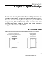
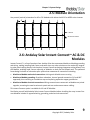
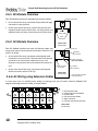
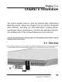
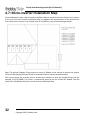
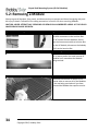
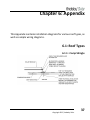
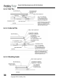
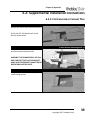
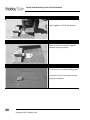
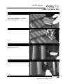
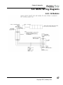
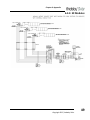
1
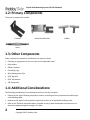
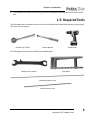
Installation Guide
Sloped Roof Mounting System
(60‐Cell Modules)
Version 2.8
Sloped Roof Mounting Sy stem (60‐Cell Modules)
No part of this publication may be reproduced, stored in a retrieval system or transmitted in any form or
by any means, electronic, mechanical, photocopying, recording, scanning or otherwise, except as per‐
mitted under Section 107 or 108 of the 1976 U.S. Copyright Act, without prior written permission from
an officer of Andalay Solar. For permission contact: Andalay Solar, 2071 Ringwood Ave, Unit C, San Jose,
CA 95131, Attn: VP of Marketing.
Trademarks: Andalay Solar, Andalay Solar Power Systems, Sun for Everyone, Instant Connect, and
related trade dress are trade names, trademarks or registered trademarks, and may not be used without
written permission.
LIMITATION OF LIABILITY/DISCLAIMER OF WARRANTY. Andalay SOLAR, ITS PARENT, SUBSIDIARIES,
AND THEIR EMPLOYEES, AGENTS, OFFICERS AND DIRECTORS (COLLECTIVELY “AUTHOR”) MAKE NO
REPRESENTATIONS OR WARRANTIES WITH RESPECT TO THE ACCURACY OR COMPLETENESS OF THE
CONTENTS OF THIS WORK AND SPECIFICALLY DISCLAIM ALL WARRANTIES, INCLUDING WITHOUT LIM‐
ITATION WARRANTIES OF FITNESS FOR A PARTICULAR PURPOSE. NO WARRANTY MAY BE CREATED OR
EXTENDED BY SALES, PROMOTIONAL MATERIALS OR CUSTOMER SERVICE. THE ADVICE AND STRATE‐
GIES CONTAINED HEREIN MAY NOT BE SUITABLE FOR EVERY SITUATION. THE CONTENTS OF THIS
WORK ARE INTENDED FOR A TARGET AUDIENCE THAT HAS SOME BASIC CONSTRUCTION AND ELECTRI‐
CAL WIRING KNOWLEDGE. THIS WORK IS SOLD WITH THE UNDERSTANDING THAT THE AUTHOR IS
NOT ENGAGED IN RENDERING LEGAL, ACCOUNTING, OR OTHER PROFESSIONAL SERVICES. IF PROFES‐
SIONAL ASSISTANCE IS REQUIRED, THE SERVICES OF A COMPETENT PROFESSIONAL PERSON SHOULD
BE SOUGHT. IN VIEW OF THE CHANGES IN LOCAL, STATE AND FEDERAL REGULATIONS, THE READER IS
URGED TO REVIEW AND EVALUATE THE INFORMATION PROVIDED BY THEIR LOCAL, STATE AND FED‐
ERAL REGULATORY AUTHORITY FOR, AMONG OTHER THINGS, ANY RULES, REGULATIONS, INSTRUC‐
TIONS, REQUIREMENTS, OR PRECAUTIONS RELATED TO THE INSTALLATION OF PV SOLAR ELECTRIC
SYSTEMS. READERS SHOULD CONSULT A LICENSED SOLAR INSTALLATION CONTRACTOR OR ELECTRI‐
CIAN WHERE APPROPRIATE. THE AUTHOR SHALL NOT BE LIABLE FOR DAMAGES ARISING HEREFROM.
Place of Origin: This manual, and the techniques, methods and IP contained within it, were created in
the United States of America. Andalay Solar systems contain some foreign made components. Assembly,
design and distribution takes place through operations located within and outside the United States of
America.
Protected by U.S. patents (7,406,800; 7,832,157; 7,866,098; 7,987,614; 8,505,248; and 8,813,460 B2),
and foreign patents (2,005,248,343; 243,626; 274,182 and 751,614). Other patents pending.
Copyright 2015, Andalay Solar
Table of Contents
1: Introduction ‐ ‐ ‐ ‐ ‐ ‐ ‐ ‐ ‐ ‐ ‐ ‐ ‐ ‐ ‐ ‐ ‐ ‐ ‐ ‐ ‐ ‐ ‐ ‐ ‐ ‐ ‐ ‐ ‐ ‐ ‐ ‐ ‐ ‐ ‐ ‐ ‐ ‐ 1
1.1: Features & Benefits ‐ ‐ ‐ ‐ ‐ ‐ ‐ ‐ ‐ ‐ ‐ ‐ ‐ ‐ ‐ ‐ ‐ ‐ ‐ ‐ ‐ ‐ ‐ ‐ ‐ ‐ ‐ ‐ ‐ ‐ ‐ ‐ ‐ ‐ ‐ ‐ ‐ ‐ ‐ 1
1.2: Primary Components ‐ ‐ ‐ ‐ ‐ ‐ ‐ ‐ ‐ ‐ ‐ ‐ ‐ ‐ ‐ ‐ ‐ ‐ ‐ ‐ ‐ ‐ ‐ ‐ ‐ ‐ ‐ ‐ ‐ ‐ ‐ ‐ ‐ ‐ ‐ ‐ ‐ ‐ ‐ 2
1.3: Other Components ‐ ‐ ‐ ‐ ‐ ‐ ‐ ‐ ‐ ‐ ‐ ‐ ‐ ‐ ‐ ‐ ‐ ‐ ‐ ‐ ‐ ‐ ‐ ‐ ‐ ‐ ‐ ‐ ‐ ‐ ‐ ‐ ‐ ‐ ‐ ‐ ‐ ‐ ‐ ‐ 2
1.4: Additional Considerations: ‐ ‐ ‐ ‐ ‐ ‐ ‐ ‐ ‐ ‐ ‐ ‐ ‐ ‐ ‐ ‐ ‐ ‐ ‐ ‐ ‐ ‐ ‐ ‐ ‐ ‐ ‐ ‐ ‐ ‐ ‐ ‐ ‐ ‐ ‐ ‐ 2
1.5: Required Tools ‐ ‐ ‐ ‐ ‐ ‐ ‐ ‐ ‐ ‐ ‐ ‐ ‐ ‐ ‐ ‐ ‐ ‐ ‐ ‐ ‐ ‐ ‐ ‐ ‐ ‐ ‐ ‐ ‐ ‐ ‐ ‐ ‐ ‐ ‐ ‐ ‐ ‐ ‐ ‐ ‐ ‐ 3
1.6: Safety Precautions ‐ ‐ ‐ ‐ ‐ ‐ ‐ ‐ ‐ ‐ ‐ ‐ ‐ ‐ ‐ ‐ ‐ ‐ ‐ ‐ ‐ ‐ ‐ ‐ ‐ ‐ ‐ ‐ ‐ ‐ ‐ ‐ ‐ ‐ ‐ ‐ ‐ ‐ ‐ ‐ 4
1.6.1: General Safety ‐ ‐ ‐ ‐ ‐ ‐ ‐ ‐ ‐ ‐ ‐ ‐ ‐ ‐ ‐ ‐ ‐ ‐ ‐ ‐ ‐ ‐ ‐ ‐ ‐ ‐ ‐ ‐ ‐ ‐ ‐ ‐ ‐ ‐ ‐ ‐ ‐ ‐ ‐ 4
1.6.2: Installation Safety ‐ ‐ ‐ ‐ ‐ ‐ ‐ ‐ ‐ ‐ ‐ ‐ ‐ ‐ ‐ ‐ ‐ ‐ ‐ ‐ ‐ ‐ ‐ ‐ ‐ ‐ ‐ ‐ ‐ ‐ ‐ ‐ ‐ ‐ ‐ ‐ ‐ 4
1.7: For Further Information ‐ ‐ ‐ ‐ ‐ ‐ ‐ ‐ ‐ ‐ ‐ ‐ ‐ ‐ ‐ ‐ ‐ ‐ ‐ ‐ ‐ ‐ ‐ ‐ ‐ ‐ ‐ ‐ ‐ ‐ ‐ ‐ ‐ ‐ ‐ ‐ ‐ 5
2: System Design ‐ ‐ ‐ ‐ ‐ ‐ ‐ ‐ ‐ ‐ ‐ ‐ ‐ ‐ ‐ ‐ ‐ ‐ ‐ ‐ ‐ ‐ ‐ ‐ ‐ ‐ ‐ ‐ ‐ ‐ ‐ ‐ ‐ ‐ ‐ ‐ ‐ 7
2.1: Module Types ‐ ‐ ‐ ‐ ‐ ‐ ‐ ‐ ‐ ‐ ‐ ‐ ‐ ‐ ‐ ‐ ‐ ‐ ‐ ‐ ‐ ‐ ‐ ‐ ‐ ‐ ‐ ‐ ‐ ‐ ‐ ‐ ‐ ‐ ‐ ‐ ‐ ‐ ‐ ‐ ‐ ‐ 7
2.2: Required Site Information ‐ ‐ ‐ ‐ ‐ ‐ ‐ ‐ ‐ ‐ ‐ ‐ ‐ ‐ ‐ ‐ ‐ ‐ ‐ ‐ ‐ ‐ ‐ ‐ ‐ ‐ ‐ ‐ ‐ ‐ ‐ ‐ ‐ ‐ ‐ ‐ 8
2.3: Preliminary Design Layout ‐ ‐ ‐ ‐ ‐ ‐ ‐ ‐ ‐ ‐ ‐ ‐ ‐ ‐ ‐ ‐ ‐ ‐ ‐ ‐ ‐ ‐ ‐ ‐ ‐ ‐ ‐ ‐ ‐ ‐ ‐ ‐ ‐ ‐ ‐ ‐ 8
2.4: Thermal Expansion Considerations ‐ ‐ ‐ ‐ ‐ ‐ ‐ ‐ ‐ ‐ ‐ ‐ ‐ ‐ ‐ ‐ ‐ ‐ ‐ ‐ ‐ ‐ ‐ ‐ ‐ ‐ ‐ ‐ ‐ ‐ ‐ ‐ 8
2.5: Module Orientation ‐ ‐ ‐ ‐ ‐ ‐ ‐ ‐ ‐ ‐ ‐ ‐ ‐ ‐ ‐ ‐ ‐ ‐ ‐ ‐ ‐ ‐ ‐ ‐ ‐ ‐ ‐ ‐ ‐ ‐ ‐ ‐ ‐ ‐ ‐ ‐ ‐ ‐ ‐ 9
2.6: Andalay Solar Instant ConnectTM AC & DC Modules ‐ ‐ ‐ ‐ ‐ ‐ ‐ ‐ ‐ ‐ ‐ ‐ ‐ ‐ ‐ ‐ ‐ ‐ ‐ ‐ ‐ ‐ ‐ 9
2.6.1: DC Module Overview ‐ ‐ ‐ ‐ ‐ ‐ ‐ ‐ ‐ ‐ ‐ ‐ ‐ ‐ ‐ ‐ ‐ ‐ ‐ ‐ ‐ ‐ ‐ ‐ ‐ ‐ ‐ ‐ ‐ ‐ ‐ ‐ ‐ ‐ ‐ 10
2.6.2: AC Module Overview ‐ ‐ ‐ ‐ ‐ ‐ ‐ ‐ ‐ ‐ ‐ ‐ ‐ ‐ ‐ ‐ ‐ ‐ ‐ ‐ ‐ ‐ ‐ ‐ ‐ ‐ ‐ ‐ ‐ ‐ ‐ ‐ ‐ ‐ ‐ 10
2.6.3: AC Wiring using Extension Cables ‐ ‐ ‐ ‐ ‐ ‐ ‐ ‐ ‐ ‐ ‐ ‐ ‐ ‐ ‐ ‐ ‐ ‐ ‐ ‐ ‐ ‐ ‐ ‐ ‐ ‐ ‐ ‐ 10
2.6.4: AC Wiring Using Interconnect Cables ‐ ‐ ‐ ‐ ‐ ‐ ‐ ‐ ‐ ‐ ‐ ‐ ‐ ‐ ‐ ‐ ‐ ‐ ‐ ‐ ‐ ‐ ‐ ‐ ‐ ‐ 11
Copyright 2015, Andalay Solar
i
Sloped Roof Mounting Sy stem (60‐Cell Modules)
3: Installation ‐ ‐ ‐ ‐ ‐ ‐ ‐ ‐ ‐ ‐ ‐ ‐ ‐ ‐ ‐ ‐ ‐ ‐ ‐ ‐ ‐ ‐ ‐ ‐ ‐ ‐ ‐ ‐ ‐ ‐ ‐ ‐ ‐ ‐ ‐ ‐ ‐ ‐ 13
3.1: Overview ‐ ‐ ‐ ‐ ‐ ‐ ‐ ‐ ‐ ‐ ‐ ‐ ‐ ‐ ‐ ‐ ‐ ‐ ‐ ‐ ‐ ‐ ‐ ‐ ‐ ‐ ‐ ‐ ‐ ‐ ‐ ‐ ‐ ‐ ‐ ‐ ‐ ‐ ‐ ‐ ‐ ‐ ‐ ‐ 13
3.2: Layout the Array ‐ ‐ ‐ ‐ ‐ ‐ ‐ ‐ ‐ ‐ ‐ ‐ ‐ ‐ ‐ ‐ ‐ ‐ ‐ ‐ ‐ ‐ ‐ ‐ ‐ ‐ ‐ ‐ ‐ ‐ ‐ ‐ ‐ ‐ ‐ ‐ ‐ ‐ ‐ ‐ 14
3.3: Unpack and Verify Components ‐ ‐ ‐ ‐ ‐ ‐ ‐ ‐ ‐ ‐ ‐ ‐ ‐ ‐ ‐ ‐ ‐ ‐ ‐ ‐ ‐ ‐ ‐ ‐ ‐ ‐ ‐ ‐ ‐ ‐ ‐ ‐ 14
3.4: Install Flashings ‐ ‐ ‐ ‐ ‐ ‐ ‐ ‐ ‐ ‐ ‐ ‐ ‐ ‐ ‐ ‐ ‐ ‐ ‐ ‐ ‐ ‐ ‐ ‐ ‐ ‐ ‐ ‐ ‐ ‐ ‐ ‐ ‐ ‐ ‐ ‐ ‐ ‐ ‐ ‐ ‐ 15
3.5: Install L Brackets ‐ ‐ ‐ ‐ ‐ ‐ ‐ ‐ ‐ ‐ ‐ ‐ ‐ ‐ ‐ ‐ ‐ ‐ ‐ ‐ ‐ ‐ ‐ ‐ ‐ ‐ ‐ ‐ ‐ ‐ ‐ ‐ ‐ ‐ ‐ ‐ ‐ ‐ ‐ ‐ 16
3.6: Install the First Module ‐ ‐ ‐ ‐ ‐ ‐ ‐ ‐ ‐ ‐ ‐ ‐ ‐ ‐ ‐ ‐ ‐ ‐ ‐ ‐ ‐ ‐ ‐ ‐ ‐ ‐ ‐ ‐ ‐ ‐ ‐ ‐ ‐ ‐ ‐ ‐ ‐ 17
3.7: Finish the First Row ‐ ‐ ‐ ‐ ‐ ‐ ‐ ‐ ‐ ‐ ‐ ‐ ‐ ‐ ‐ ‐ ‐ ‐ ‐ ‐ ‐ ‐ ‐ ‐ ‐ ‐ ‐ ‐ ‐ ‐ ‐ ‐ ‐ ‐ ‐ ‐ ‐ ‐ 18
3.8: Add the First Module of the Next Row ‐ ‐ ‐ ‐ ‐ ‐ ‐ ‐ ‐ ‐ ‐ ‐ ‐ ‐ ‐ ‐ ‐ ‐ ‐ ‐ ‐ ‐ ‐ ‐ ‐ ‐ ‐ ‐ ‐ 20
3.9: Completing the Rest of the Array ‐ ‐ ‐ ‐ ‐ ‐ ‐ ‐ ‐ ‐ ‐ ‐ ‐ ‐ ‐ ‐ ‐ ‐ ‐ ‐ ‐ ‐ ‐ ‐ ‐ ‐ ‐ ‐ ‐ ‐ ‐ 22
3.10: Alternate Method of Securing Moduless ‐ ‐ ‐ ‐ ‐ ‐ ‐ ‐ ‐ ‐ ‐ ‐ ‐ ‐ ‐ ‐ ‐ ‐ ‐ ‐ ‐ ‐ ‐ ‐ ‐ ‐ ‐ 22
4: Wiring ‐ ‐ ‐ ‐ ‐ ‐ ‐ ‐ ‐ ‐ ‐ ‐ ‐ ‐ ‐ ‐ ‐ ‐ ‐ ‐ ‐ ‐ ‐ ‐ ‐ ‐ ‐ ‐ ‐ ‐ ‐ ‐ ‐ ‐ ‐ ‐ ‐ ‐ ‐ ‐ ‐ 23
4.1: DC Modules ‐ ‐ ‐ ‐ ‐ ‐ ‐ ‐ ‐ ‐ ‐ ‐ ‐ ‐ ‐ ‐ ‐ ‐ ‐ ‐ ‐ ‐ ‐ ‐ ‐ ‐ ‐ ‐ ‐ ‐ ‐ ‐ ‐ ‐ ‐ ‐ ‐ ‐ ‐ ‐ ‐ ‐ 23
4.1.1: String Sizes ‐ ‐ ‐ ‐ ‐ ‐ ‐ ‐ ‐ ‐ ‐ ‐ ‐ ‐ ‐ ‐ ‐ ‐ ‐ ‐ ‐ ‐ ‐ ‐ ‐ ‐ ‐ ‐ ‐ ‐ ‐ ‐ ‐ ‐ ‐ ‐ ‐ ‐ ‐ ‐ 23
4.1.2: Wiring Requirements ‐ ‐ ‐ ‐ ‐ ‐ ‐ ‐ ‐ ‐ ‐ ‐ ‐ ‐ ‐ ‐ ‐ ‐ ‐ ‐ ‐ ‐ ‐ ‐ ‐ ‐ ‐ ‐ ‐ ‐ ‐ ‐ ‐ ‐ ‐ 23
4.1.3: Wiring DC Modules ‐ ‐ ‐ ‐ ‐ ‐ ‐ ‐ ‐ ‐ ‐ ‐ ‐ ‐ ‐ ‐ ‐ ‐ ‐ ‐ ‐ ‐ ‐ ‐ ‐ ‐ ‐ ‐ ‐ ‐ ‐ ‐ ‐ ‐ ‐ ‐ 24
4.2: AC Module with M215 or M250 Micro‐Inverter ‐ ‐ ‐ ‐ ‐ ‐ ‐ ‐ ‐ ‐ ‐ ‐ ‐ ‐ ‐ ‐ ‐ ‐ ‐ ‐ ‐ ‐ ‐ ‐ 25
4.2.1: Branch Sizes ‐ ‐ ‐ ‐ ‐ ‐ ‐ ‐ ‐ ‐ ‐ ‐ ‐ ‐ ‐ ‐ ‐ ‐ ‐ ‐ ‐ ‐ ‐ ‐ ‐ ‐ ‐ ‐ ‐ ‐ ‐ ‐ ‐ ‐ ‐ ‐ ‐ ‐ ‐ 25
4.2.2: Wiring Requirements ‐ ‐ ‐ ‐ ‐ ‐ ‐ ‐ ‐ ‐ ‐ ‐ ‐ ‐ ‐ ‐ ‐ ‐ ‐ ‐ ‐ ‐ ‐ ‐ ‐ ‐ ‐ ‐ ‐ ‐ ‐ ‐ ‐ ‐ ‐ 26
4.2.3: Wiring AC Modules with the M215 or M250 Micro‐inverter ‐ ‐ ‐ ‐ ‐ ‐ ‐ ‐ ‐ ‐ ‐ ‐ ‐ ‐ 27
4.3: Mixed M215/M250 Branches ‐ ‐ ‐ ‐ ‐ ‐ ‐ ‐ ‐ ‐ ‐ ‐ ‐ ‐ ‐ ‐ ‐ ‐ ‐ ‐ ‐ ‐ ‐ ‐ ‐ ‐ ‐ ‐ ‐ ‐ ‐ ‐ ‐ 28
4.4: Lightning Surge Suppression ‐ ‐ ‐ ‐ ‐ ‐ ‐ ‐ ‐ ‐ ‐ ‐ ‐ ‐ ‐ ‐ ‐ ‐ ‐ ‐ ‐ ‐ ‐ ‐ ‐ ‐ ‐ ‐ ‐ ‐ ‐ ‐ ‐ ‐ 28
4.5: Junction Boxes ‐ ‐ ‐ ‐ ‐ ‐ ‐ ‐ ‐ ‐ ‐ ‐ ‐ ‐ ‐ ‐ ‐ ‐ ‐ ‐ ‐ ‐ ‐ ‐ ‐ ‐ ‐ ‐ ‐ ‐ ‐ ‐ ‐ ‐ ‐ ‐ ‐ ‐ ‐ ‐ ‐ 29
4.6: Grounding the Array ‐ ‐ ‐ ‐ ‐ ‐ ‐ ‐ ‐ ‐ ‐ ‐ ‐ ‐ ‐ ‐ ‐ ‐ ‐ ‐ ‐ ‐ ‐ ‐ ‐ ‐ ‐ ‐ ‐ ‐ ‐ ‐ ‐ ‐ ‐ ‐ ‐ ‐ 29
4.6.1: Grounding the Array to the Junction Box ‐ ‐ ‐ ‐ ‐ ‐ ‐ ‐ ‐ ‐ ‐ ‐ ‐ ‐ ‐ ‐ ‐ ‐ ‐ ‐ ‐ ‐ ‐ ‐ 30
4.7: Micro‐inverter Installation Map ‐ ‐ ‐ ‐ ‐ ‐ ‐ ‐ ‐ ‐ ‐ ‐ ‐ ‐ ‐ ‐ ‐ ‐ ‐ ‐ ‐ ‐ ‐ ‐ ‐ ‐ ‐ ‐ ‐ ‐ ‐ ‐ 32
ii
Copyright 2015, Andalay Solar
Table of Contents
5: Servicing ‐ ‐ ‐ ‐ ‐ ‐ ‐ ‐ ‐ ‐ ‐ ‐ ‐ ‐ ‐ ‐ ‐ ‐ ‐ ‐ ‐ ‐ ‐ ‐ ‐ ‐ ‐ ‐ ‐ ‐ ‐ ‐ ‐ ‐ ‐ ‐ ‐ ‐ ‐ 33
5.1: Maintenance Considerations ‐ ‐ ‐ ‐ ‐ ‐ ‐ ‐ ‐ ‐ ‐ ‐ ‐ ‐ ‐ ‐ ‐ ‐ ‐ ‐ ‐ ‐ ‐ ‐ ‐ ‐ ‐ ‐ ‐ ‐ ‐ ‐ ‐ ‐ 33
5.2: Removing a Module ‐ ‐ ‐ ‐ ‐ ‐ ‐ ‐ ‐ ‐ ‐ ‐ ‐ ‐ ‐ ‐ ‐ ‐ ‐ ‐ ‐ ‐ ‐ ‐ ‐ ‐ ‐ ‐ ‐ ‐ ‐ ‐ ‐ ‐ ‐ ‐ ‐ ‐ 34
5.3: Removing a Micro‐Inverter ‐ ‐ ‐ ‐ ‐ ‐ ‐ ‐ ‐ ‐ ‐ ‐ ‐ ‐ ‐ ‐ ‐ ‐ ‐ ‐ ‐ ‐ ‐ ‐ ‐ ‐ ‐ ‐ ‐ ‐ ‐ ‐ ‐ ‐ ‐ 35
6: Appendix ‐ ‐ ‐ ‐ ‐ ‐ ‐ ‐ ‐ ‐ ‐ ‐ ‐ ‐ ‐ ‐ ‐ ‐ ‐ ‐ ‐ ‐ ‐ ‐ ‐ ‐ ‐ ‐ ‐ ‐ ‐ ‐ ‐ ‐ ‐ ‐ ‐ ‐ ‐ 37
6.1: Roof Types ‐ ‐ ‐ ‐ ‐ ‐ ‐ ‐ ‐ ‐ ‐ ‐ ‐ ‐ ‐ ‐ ‐ ‐ ‐ ‐ ‐ ‐ ‐ ‐ ‐ ‐ ‐ ‐ ‐ ‐ ‐ ‐ ‐ ‐ ‐ ‐ ‐ ‐ ‐ ‐ ‐ ‐ ‐ 37
6.1.1: Comp Shingle ‐ ‐ ‐ ‐ ‐ ‐ ‐ ‐ ‐ ‐ ‐ ‐ ‐ ‐ ‐ ‐ ‐ ‐ ‐ ‐ ‐ ‐ ‐ ‐ ‐ ‐ ‐ ‐ ‐ ‐ ‐ ‐ ‐ ‐ ‐ ‐ ‐ ‐ 37
6.1.2: Flat Tile ‐ ‐ ‐ ‐ ‐ ‐ ‐ ‐ ‐ ‐ ‐ ‐ ‐ ‐ ‐ ‐ ‐ ‐ ‐ ‐ ‐ ‐ ‐ ‐ ‐ ‐ ‐ ‐ ‐ ‐ ‐ ‐ ‐ ‐ ‐ ‐ ‐ ‐ ‐ ‐ ‐ ‐ 38
6.1.3: S‐Barrel Tile ‐ ‐ ‐ ‐ ‐ ‐ ‐ ‐ ‐ ‐ ‐ ‐ ‐ ‐ ‐ ‐ ‐ ‐ ‐ ‐ ‐ ‐ ‐ ‐ ‐ ‐ ‐ ‐ ‐ ‐ ‐ ‐ ‐ ‐ ‐ ‐ ‐ ‐ ‐ ‐ 38
6.1.4: Standing Seam ‐ ‐ ‐ ‐ ‐ ‐ ‐ ‐ ‐ ‐ ‐ ‐ ‐ ‐ ‐ ‐ ‐ ‐ ‐ ‐ ‐ ‐ ‐ ‐ ‐ ‐ ‐ ‐ ‐ ‐ ‐ ‐ ‐ ‐ ‐ ‐ ‐ ‐ 38
6.2: Supplemental Installation Instructions ‐ ‐ ‐ ‐ ‐ ‐ ‐ ‐ ‐ ‐ ‐ ‐ ‐ ‐ ‐ ‐ ‐ ‐ ‐ ‐ ‐ ‐ ‐ ‐ ‐ ‐ ‐ ‐ ‐ 39
6.2.1: Flat Concrete or Cement Tiles ‐ ‐ ‐ ‐ ‐ ‐ ‐ ‐ ‐ ‐ ‐ ‐ ‐ ‐ ‐ ‐ ‐ ‐ ‐ ‐ ‐ ‐ ‐ ‐ ‐ ‐ ‐ ‐ ‐ ‐ 39
6.2.2: S or Barrel Tiles ‐ ‐ ‐ ‐ ‐ ‐ ‐ ‐ ‐ ‐ ‐ ‐ ‐ ‐ ‐ ‐ ‐ ‐ ‐ ‐ ‐ ‐ ‐ ‐ ‐ ‐ ‐ ‐ ‐ ‐ ‐ ‐ ‐ ‐ ‐ ‐ ‐ ‐ 41
6.3: M215 Wiring Diagrams ‐ ‐ ‐ ‐ ‐ ‐ ‐ ‐ ‐ ‐ ‐ ‐ ‐ ‐ ‐ ‐ ‐ ‐ ‐ ‐ ‐ ‐ ‐ ‐ ‐ ‐ ‐ ‐ ‐ ‐ ‐ ‐ ‐ ‐ ‐ ‐ ‐ 44
6.3.1: 17 Modules ‐ ‐ ‐ ‐ ‐ ‐ ‐ ‐ ‐ ‐ ‐ ‐ ‐ ‐ ‐ ‐ ‐ ‐ ‐ ‐ ‐ ‐ ‐ ‐ ‐ ‐ ‐ ‐ ‐ ‐ ‐ ‐ ‐ ‐ ‐ ‐ ‐ ‐ ‐ ‐ 44
6.3.2: 34 Modules ‐ ‐ ‐ ‐ ‐ ‐ ‐ ‐ ‐ ‐ ‐ ‐ ‐ ‐ ‐ ‐ ‐ ‐ ‐ ‐ ‐ ‐ ‐ ‐ ‐ ‐ ‐ ‐ ‐ ‐ ‐ ‐ ‐ ‐ ‐ ‐ ‐ ‐ ‐ ‐ 45
6.3.3: 45 Modules ‐ ‐ ‐ ‐ ‐ ‐ ‐ ‐ ‐ ‐ ‐ ‐ ‐ ‐ ‐ ‐ ‐ ‐ ‐ ‐ ‐ ‐ ‐ ‐ ‐ ‐ ‐ ‐ ‐ ‐ ‐ ‐ ‐ ‐ ‐ ‐ ‐ ‐ ‐ ‐ 46
6.4: M250 Wiring Diagrams ‐ ‐ ‐ ‐ ‐ ‐ ‐ ‐ ‐ ‐ ‐ ‐ ‐ ‐ ‐ ‐ ‐ ‐ ‐ ‐ ‐ ‐ ‐ ‐ ‐ ‐ ‐ ‐ ‐ ‐ ‐ ‐ ‐ ‐ ‐ ‐ ‐ 47
6.4.1: 16 Modules ‐ ‐ ‐ ‐ ‐ ‐ ‐ ‐ ‐ ‐ ‐ ‐ ‐ ‐ ‐ ‐ ‐ ‐ ‐ ‐ ‐ ‐ ‐ ‐ ‐ ‐ ‐ ‐ ‐ ‐ ‐ ‐ ‐ ‐ ‐ ‐ ‐ ‐ ‐ ‐ 47
6.4.2: 32 Modules ‐ ‐ ‐ ‐ ‐ ‐ ‐ ‐ ‐ ‐ ‐ ‐ ‐ ‐ ‐ ‐ ‐ ‐ ‐ ‐ ‐ ‐ ‐ ‐ ‐ ‐ ‐ ‐ ‐ ‐ ‐ ‐ ‐ ‐ ‐ ‐ ‐ ‐ ‐ ‐ 48
6.4.3: 39 Modules ‐ ‐ ‐ ‐ ‐ ‐ ‐ ‐ ‐ ‐ ‐ ‐ ‐ ‐ ‐ ‐ ‐ ‐ ‐ ‐ ‐ ‐ ‐ ‐ ‐ ‐ ‐ ‐ ‐ ‐ ‐ ‐ ‐ ‐ ‐ ‐ ‐ ‐ ‐ ‐ 49
7: Support ‐ ‐ ‐ ‐ ‐ ‐ ‐ ‐ ‐ ‐ ‐ ‐ ‐ ‐ ‐ ‐ ‐ ‐ ‐ ‐ ‐ ‐ ‐ ‐ ‐ ‐ ‐ ‐ ‐ ‐ ‐ ‐ ‐ ‐ ‐ ‐ ‐ ‐ ‐ 51
7.1: Contacting Andalay Solar ‐ ‐ ‐ ‐ ‐ ‐ ‐ ‐ ‐ ‐ ‐ ‐ ‐ ‐ ‐ ‐ ‐ ‐ ‐ ‐ ‐ ‐ ‐ ‐ ‐ ‐ ‐ ‐ ‐ ‐ ‐ ‐ ‐ ‐ ‐ ‐ 51
Copyright 2015, Andalay Solar
iii
Sloped Roof Mounting Sy stem (60‐Cell Modules)
This page intentionally left blank.
iv
Copyright 2015, Andalay Solar
Chapter 1: Introduction
Andalay Solar systems require 80% fewer parts than ordinary DC
solar systems; the simplicity of having fewer parts transfers directly
into the ease of the design process.
1.1: Features & Benefits
Rapid design and installation
•
Design eliminates need for separate rack systems
•
Automates panel‐to‐panel mounting, grounding, and electrical connections. •
80% fewer parts and 50% less labor than ordinary solar power systems.
Designed for all roof types
•
Composition Shingle
•
Flat Tile
•
S and Barrel Tile
•
Standing Seam
•
Flat Roof (refer to the Andalay Solar 5◦ Flat Roof Mounting System Installation Guide)
Ruggedized construction
•
Engineered to exceed wind and snow load requirements established by local building codes, enabling installations in more regions.
Copyright 2015, Andalay Solar
1
Sloped Roof Mounting Sy stem (60‐Cell Modules)
1.2: Primary Components
The primary components include:
L Bracket
North/South Bracket
G‐Bolts
Splice
1.3: Other Components
Other components required for installation (not shown) include:
•
Flashings as appropriate for the roof type and all applicable codes
•
Roof sealant
•
Offset L brackets
•
Grounding Lugs
•
Wire Management Clips
•
5/16” lag bolts
•
5/16” flat washers
•
3/8” flange nuts
1.4: Additional Considerations:
The following considerations must be determined on a case‐by‐case basis:
•
Determine the type of flashing required to conform to roofing warranty requirements and all appli‐
cable building codes.
•
Determine the type of roofing sealant required to conform to all applicable building codes.
•
Refer to the Technical Evaluation Report, available at http://www.andalaysolar.com/resources, to determine adequate lag bolt strength, or G‐bolts.
2
Copyright 2015, Andalay Solar
Chapter 1: Introduction
•
The Andalay Solar Sloped Roof Mounting System is designed to work with 60‐cell AC and DC Mod‐
ules.
1.5: Required Tools
The following tools are needed in order to install the Andalay Solar Sloped Roof Mounting System (avail‐
able from any tool source):
Ratchet (1/4” drive)
Torque Wrench
Power driver
The following special tools are available from Andalay Solar:
Andalay Solar wrench
Step Block
Landscape Splice Driver
Portrait Splice Driver
Copyright 2015, Andalay Solar
3
Sloped Roof Mounting Sy stem (60‐Cell Modules)
1.6: Safety Precautions
Installation procedures should be performed in compliance with local Authority Having Jurisdiction reg‐
ulations, OSHA protection codes, most recent National Electrical Code, ANSI/NFPA 70, local utility
requirements, and other applicable guidelines that pertain. For more information, please check the
OSHA Part 1926 for information regarding safety.
1.6.1: General Safety
•
Fall Hazards: OSHA Part 1926‐Subpart M contains fall‐protection regulations for all roof edges, including all necessary guardrail systems, personal fall arrest systems, safety net systems, warning line systems, safety monitoring systems, controlled access zones, and other required protective equipment and measures
•
Weather Hazards: Performing installations in overcast conditions can cause severe bodily injury.
•
Electrical Hazards: OSHA Part 1926‐Subpart K contains hazard‐protection regulations for working with live electrical equipment and/or high voltage, including a 10’ minimum clearance from over‐
head power lines and using the proper barriers and other forms of guarding when live parts of elec‐
tric equipment and circuits are exposed.
•
Lifting Hazards: Always follow smart lifting practices to avoid back and general body injury. For more information, check Section VII: Chapter 1 in the OSHA Technical Manual.
•
Hand and Power Tools: OSHA Part 1926‐Subpart I contains regulations regarding tool usage during installation. Always check equipment before use to verify correct functionality and avoid any bodily injuries. Always secure and properly store all equipment when not in use.
•
Materials Handling: OSHA Part 1926‐Subpart H requires that all materials shall be stacked, inter‐
locked, and secured to prevent sliding, falling, or collapsing, which could cause severe body harm. Handle sharp edges of system components using proper equipment.
1.6.2: Installation Safety
•
Installation procedures should be performed by trained and licensed personnel who are experienced in installing photovoltaic systems.
•
Do not expose Modules to excessive loads as this might cause damage and malfunction.
•
Always use proper safety and installation gear such as (but not limited to) gloves, goggles, hard hats and head protection, hearing protection, safety vests, and proper tools.
•
Solar Modules generate electricity when exposed to light and can cause lethal shock and burn haz‐
ards.
•
Perform all electrical installations in accordance with all local electrical codes and the National Elec‐
trical Code (NEC), ANSI/NFPA 70.
•
Follow NEC requirements for grounding, including those in Article 250 and Article 690.
4
Copyright 2015, Andalay Solar
Chapter 1: Introduction
•
Only qualified personnel should install, service, and/or replace Andalay Modules. Electrical compo‐
nents can be dangerous for installation personnel who are unfamiliar with appropriate safety proce‐
dures.
•
Read all instructions and cautionary markings in this manual before installing or using the Andalay Module
•
Tampering with Modules may void the warranty and/or cause serious bodily injury. Modules contain no user‐serviceable parts. To replace a defective Module, please contact Andalay customer service to obtain an RMA number.
•
Never connect or disconnect a Module when the system is energized. Only energize the system once all Modules are completely assembled and inspected.
•
Never touch live terminals with bare hands. Use insulated tools for electrical connections.
•
Never strike glass Module surfaces with heavy or sharp objects, and never walk on Module surfaces. The glass surface may fracture, disabling the Module and voiding the warranty.
•
Never direct artificially‐concentrated sunlight onto the Modules.
1.7: For Further Information
Please refer to the PV Module Installation and Operations manual available at www.andalaysolar.com/
resources for additional information and instructions for installing Andalay Solar AC and DC PV Modules,
including:
•
Additional safety instructions
•
Regulatory information
•
Recommended Applications
•
Bonding
•
Wiring
•
Commissioning
The information in the Installation and Operations manual varies by Module type/model and is beyond
the scope of this manual.
Copyright 2015, Andalay Solar
5
Sloped Roof Mounting Sy stem (60‐Cell Modules)
This page intentionally left blank.
6
Copyright 2015, Andalay Solar
Chapter 2: System Design
Andalay Solar Power Systems deliver the powerful performance you
need with the reliability you’ve come to expect from our products.
Our solar solutions not only decrease dependency on fossil‐fueled
energy sources, but will dramatically reduce—in some cases even
eliminate—your home energy bill. Andalay Solar makes generating
energy from the sun easy and affordable.
2.1: Module Types
Andalay Solar sloped roof mounting systems are compatible with the following types of Modules:
Copyright 2015, Andalay Solar
7
Sloped Roof Mounting Sy stem (60‐Cell Modules)
2.2: Required Site Information
Begin designing the site by completing a site survey:
•
Project contact name, phone number, and email
•
Project address
•
Roof measurements, type, pitch, and azimuth
•
Rafter type, size, and spacing
•
Obstructions and shading
•
Array layout and dimensions
•
Fire setback and other local AHJ requirements
•
Other important information such as design wind speed (MPH), exposure category, snow load, and seismic zone
2.3: Preliminary Design Layout
Before developing a design layout, be familiar with Andalay Solar panels unique parameters. As Andalay
Solar panels are connected together, they form a rigid structure, and not single rows of panels on inde‐
pendent racking systems as with ordinary solar panels. The frames of Andalay Solar panels is where the
“groove” is accessible and will serve as connection between the array and the chosen roof‐mounting
solution. The stainless steel Andalay Solar splices ground and connect panels in the East‐West direction
and serve as structural components. The stainless steel G‐Bolt mechanically attaches and grounds the
array in the North‐South direction, and enables sharing of footings between the first and second rows
(and all consecutive rows until the top of array). In an array layout, include a 1” gap between rows in
North/South direction to accommodate the installation of North/South brackets.
Refer to the Technical Evaluation Report to determine maximum allowable anchor spacing. Panels which
overhang the last footing in a row may stick out no more than a maximum of 16" from that footing. The
completed design layout should include the plan layout, specification sheets, and BOM. For every proj‐
ect, the designer in charge must verify any structural engineering review requirements with local AHJ
officials and obtain a professional structural engineering stamp (P.E.) if needed. Alternatively, Andalay
Solar can provide engineering services and/or a P.E. stamp for wind and seismic calculations at an addi‐
tional cost.
2.4: Thermal Expansion Considerations
For thermal expansion, include a 1” gap for every more than 17 Modules (portrait). For bigger configura‐
tions, you may place separate arrays next to each other to give the appearance of a single array, if
desired.
8
Copyright 2015, Andalay Solar
Chapter 2: System Design
2.5: Module Orientation
Use portrait (vertical) orientation for AC or DC Modules with either the M215 or M250 micro‐inverter.
4'
= L Bracket
= North-South Bracket
2.6: Andalay Solar Instant ConnectTM AC & DC
Modules
Instant Connect™ is a line of products from Andalay Solar that automates Module‐to‐Module grounding
and wiring, making installing solar, faster, and easier than any other solution on the market. By integrat‐
ing solar panel racking directly into the panel, Instant Connect technology integrates racking directly into
the Module, enabling rapid, secure mounting of Modules on both flat and sloped roofs. The patented
frame design includes an innovative splice system that automates all connections including:
•
Module‐to‐Module mechanical connections: Joining each Module across a string.
•
Module‐to‐Module grounding: Provides a redundant, internal ground connection (U/L and NEC approved), thus removing an installation step and replacing expensive copper ground wire.
•
Module‐to‐Module electrical connections: Wiring connections are automatic as Modules are joined together, removing the need to wire each panel and use cumbersome custom cabling.
This Instant Connect option is available for AC and DC Modules.
Familiarize yourself with Andalay Solar Instant Connect Modules before installing the array. Instant Con‐
nect Modules include UL‐approved wiring, grounding, and electrical connections.
Copyright 2015, Andalay Solar
9
Sloped Roof Mounting Sy stem (60‐Cell Modules)
2.6.1: DC Module Overview
Each DC Module comes with extended junction box cables:
•
At one end of the array, terminate the positive and nega‐
tive leads in a junction box.
•
At the other end of the array, remove the positive and negative leads from the frame slots. Join the positive and negative leads, and then zip‐tie them to the frame slots.
Module junction box
-
+
-
+
Built-in
jumper cable
MC4
connectors
2.6.2: AC Module Overview
FRONT VIEW
(not to scale)
Each AC Module includes one male and female output con‐
nector that must be terminated as instructed in Sections 2.6.3
and 2.6.4, below:
•
Module junction box
Enphase
Micro-inverter
At one end of the array, terminate each exposed male connector in a junction box. The male side of the branch connects to an interconnect cable that in turn runs directly to the junction box at the head of the branch cir‐
cuit.
•
Male connector1
NOT TOUCH SAFE
Female connector2
(touch safe)
At the other end of the array, terminate each exposed female connector with an End Cap.
FRONT VIEW
(not to scale)
2.6.3: AC Wiring using Extension Cables
T-Cable/
Side Connectors
1 = Interconnection side (M)
2 = End Cap side (F)
In most cases, you can simplify array wiring by rotating each row of Instant Connect Modules 180
degrees and using extension cables, as shown below.
3
1
2
2
2
2
2
2
2
2
2
2
2
2
5
6
4
1 = 8' Extension Cable
2 = Instant Connect AC Module
3 = Junction Box
4 = AC Interconnect Cable
5 = Male connector
6 = Female connector & End Cap
FRONT VIEW
(not to scale)
10
Copyright 2015, Andalay Solar
Chapter 2: System Design
2.6.4: AC Wiring Using Interconnect Cables
If you opt not to rotate the Modules, be sure to terminate each female connector with an End Cap and
use pigtails to connect each exposed male connector to a junction box, as shown below.
5
2
2
2
2
2
4
4
1 = Female connector & End Cap
2 = Instant Connect AC Module
3 = Junction Box
4 = AC Interconnect Cable
5 = Male connector
1
5
2
2
2
2
2
3
2
2
2
2
2
5
4
TOP VIEW
(not to scale)
Copyright 2015, Andalay Solar
11
Sloped Roof Mounting Sy stem (60‐Cell Modules)
This page intentionally left blank.
12
Copyright 2015, Andalay Solar
Chapter 3: Installation
This section explains how to install the Andalay Solar Sloped Roof
Mounting System. Please see Chapter 1 for the full list of required
parts, fasteners, and tools. For more information including photos,
specification sheets, certifications, and Technical Evaluation Reports,
visit Andalay Solar at http://www.Andalaysolar.com/resources.
CAUTION: CONSIDER THE WEIGHT AND PLACEMENT OF STAGED MATERIALS ON THE ROOF TO ENSURE
ADEQUATE STRUCTURAL SUPPORT.
3.1: Overview
This rendering illustrates how the Andalay Solar Sloped Roof Mounting System assembles (actual parts
may vary slightly). Please see the Appendix (Chapter 6.1) for additional roof attachment methods.
Copyright 2015, Andalay Solar
13
Sloped Roof Mounting Sy stem (60‐Cell Modules)
3.2: Layout the Array
To lay out a PORTRAIT array:
"
5' 6
4'
Use a chalk line to lay out the array using the dimensions specified in the system design. North/South lines should be cen‐
tered on rafters or other structural mem‐
bers if using penetrating roof components (see Section 3.3). Allow a 1” N/S gap and a 1/8” E/W gap between modules, as shown.
Note: This manual depicts a portrait instal‐
lation; the procedure is the same for both landscape and portrait installations.
3.3: Unpack and Verify Components
Unpack and stage the components.
Verify that you have the correct quantities of all required components before begin‐
ning the installation.
Note: See Section 6.2 for installation instructions on flat concrete/cement tiles, or S/barrel tiles.
14
Copyright 2015, Andalay Solar
Chapter 3: Installation
3.4: Install Flashings
Prepare the roof. (1
Lay out the roof as described in Section 3.2.
Cut the roofing as needed to accommodate the Flashing and then drill a pilot hole for the 5/16” Lag‐Bolt.
Note: The Technical Evaluation Report lists minimum rafter penetration requirements.
Remove sawdust and other debris. (2
Loosen the composition shingle directly above the pre‐drilled roof penetration. Make sure to remove any nails, staples, or debris that will interfere with the Composi‐
tion Mount Flashing.
Apply roofing sealant to the Flashing. (3
Backfill the roof penetration applying a lib‐
eral amount of sealant to the immediate area.
Apply appropriately rated roofing sealant to the underside of the Flashing in accordance with manufacturer instructions.
Slide the Flashing under the overlapping shingles. (4
The bolt hole in the Flashing must align with the hole you drilled in Step 1.
Press the Flashing firmly against the roof once properly positioned to ensure a tight seal.
Copyright 2015, Andalay Solar
15
Sloped Roof Mounting Sy stem (60‐Cell Modules)
3.5: Install L Brackets
1) Secure L Bracket to the roof.
Use one 5/16” Lag‐Bolt and flat washer per L Bracket.
2) Tighten the Lag‐Bolt using a power driver.
Tighten the Lag‐Bolt until the head of the lag bolt is 1/8” from seating on the fender washer. The 1/8” gap allow installers to line up and adjust the L‐bracket before tighten‐
ing to final position.
3) Verify proper L Bracket installation.
Use a string to align a row of attachments. Torque the lag bolt to the L‐bracket to 15‐20 ft/lbs.
Note: Installed Flashing and L Bracket assemblies are called Standoffs.
16
Copyright 2015, Andalay Solar
Chapter 3: Installation
Install the remaining Standoffs. (4
Repeat Sections 3.4 and 3.5 for each of the remaining Standoffs.
3.6: Install the First Module
Place Hex Bolts in Module channels. (1
Slide one G‐Bolt into the Module C channel for each Standoff.
Note: G‐Bolts go into the channel on the short side of the Module for portrait instal‐
lations; they go into the channel on the long side of the Module for landscape installa‐
tions.
Lift the Module into position. (2
Lift the Module into position and slide the G‐Bolts into the slots in the L‐Brackets. Loosely thread a Hex Nut on each bolt.
The module will temporarily rest on the
3/8” hardware left loose, allowing installers to line‐up and adjust the modules before tightening to final position.
Copyright 2015, Andalay Solar
17
Sloped Roof Mounting Sy stem (60‐Cell Modules)
3) Insert LH Splice.
Insert a Splice (LH end) into the Module through the Splice insertion hole with the
three rings above it.
Thread the Splice (on the end with three rings) counter‐clockwise into the Module approximately 1/2 turn.
4) Insert RH Splice.
Insert a Splice (RH end) into the Module through the hole without any rings above it.
Thread the Splice (on the end without any rings) into the Module approximately 1/2 turn.
3.7: Finish the First Row
1) Insert LH Splice.
Lift the next Module into position.
The Splices in the first Module should go into the holes in the next Module.
18
Copyright 2015, Andalay Solar
Chapter 3: Installation
Level the Modules using a Step Block. (2
Place Step Blocks under the Modules as needed to level the Modules.
Lift the Module before inserting or adjust‐
ing a Step Block. Gently lower the Module onto the Step Block when ready.
Use a Splice Driver to tighten the Splices and secure the Module. (3
The hex end of a Splice fits into the socket at the end of the Splice Driver.
Attach a ratchet to the other end of the Splice Driver.
Note: Alternatively, you may use an Andalay Solar wrench between the Modules to tighten the Splices and skip both this step and Step 4. See Section 3.10.
Insert the Splice Driver into the holes in the Module. (4
The Splice Driver slides through the Module to engage with the Splices.
Torque the Splices to 5‐7 foot‐pounds. The front Splice tightens LH and the rear Splice tightens RH. Have a helper ensure that the Modules are tightening together.
Secure the Module to the Standoffs. (5
Use a level to align Modules, then torque to the G‐Bolts to 20‐25 ft/lbs.
You may remove the Step Blocks once the Modules are secure.
Copyright 2015, Andalay Solar
19
Sloped Roof Mounting Sy stem (60‐Cell Modules)
6) Repeat Steps 1‐5 for the remaining Modules in the first row.
Secure the rest of the Modules in the cur‐
rent row to the array as described in Steps 1‐5.
Proceed to Section 3.9 when you reach the end of the row.
3.8: Add the First Module of the Next Row
1) Add North/South Brackets.
Remove the Hex Nuts from the G‐Bolts on the Standoffs between rows.
Add one North/South Bracket to each Standoff and then replace the Hex Nuts.
2) Secure the Hex Nuts.
Use an Andalay Solar wrench to loosely install the Hex Nuts.
Use a torque wrench to tighten the Hex Nuts to 15‐20 foot‐pounds.
3) Finish securing the Lag‐Bolts to the first‐row Standoffs.
Use a power driver to loosely install the Lag‐
Bolts securing the front‐row Standoffs to the roof. Use a torque wrench to tighten the Lag‐
Bolts to 15‐20 foot‐pounds.
20
Copyright 2015, Andalay Solar
Chapter 3: Installation
Add the first Module of the next row. (4
Slide upper row module into the ears of the North‐South bracket from Step 1‐3 of Sec‐
tion 3.9. Use step block to hold module in position.
Add G‐Bolts to the first Module of the next row. (5
Slide one G‐Bolt into the C channel of next Module on the side facing the first row of Modules.
Add one Hex Nut to each G‐Bolt and thread on about 1/2 turn.
Note: G‐Bolts ground the array across rows to form a continuous grounding path.
Secure the Module to the North/South Brackets. (6
Align the Module.
Use an Andalay Solar wrench to loosely install the G‐Bolts.
Use a torque wrench to tighten the G‐Bolts to 20‐25 foot‐pounds.
Position the Module on the upper Standoffs. (7
Slide the G‐Bolts on the upper side of the Module into the slots in the Standoffs. Use an Andalay Solar wrench to loosely install the G‐Bolts. Use a torque wrench to tighten the G‐Bolts to 20‐25 foot‐pounds.
Copyright 2015, Andalay Solar
21
Sloped Roof Mounting Sy stem (60‐Cell Modules)
3.9: Completing the Rest of the Array
1) Install the remaining Modules in the array.
Repeat Steps 1‐7 in Section 3.8 for the remaining Modules in the array.
2) Ground the Array.
Attach a Grounding Conductor to the grounding hole in the outer edge of the first Module in each row, then connect a #6 solid bare copper grounding wire (or other gauge as required by local building codes) to the building ground as described in Section 4.3.
Note: If you used G‐Bolt for inter‐row attachments, then the Grounding Connector is only needed at the first Module of the first row to ground the array to the junction box.
3.10: Alternate Method of Securing Modules
You may use an Andalay Solar wrench instead of a Splice Driver to secure Modules.
As described in Steps 3 and 4 of Section 3.7, you may use an Andalay Solar wrench to secure Modules instead of a Splice Driver.
To do this, use the open end of the wrench to tighten the Splice. Rotate away from the Module to tighten, as shown.
22
Copyright 2015, Andalay Solar
Chapter 4: Wiring
This chapter contains instructions for wiring Andalay Solar PV Mod‐
ules. Find the type of Module being used in the system and wire it as
you build the array.
4.1: DC Modules
Andalay Solar DC Modules are designed to be self‐wiring in each string. The first Module in each string
connects to extension cables that typically lead to a combiner box. The last Module in each string can be
reconfigured by attaching the two end MC‐4 connectors together, thereby completing the string circuit.
Secure extra cabling to the Module frames using Wire Management Clips.
CAUTION: MODULE WIRING IS ARRANGED FOR SERIES CONNECTIONS ONLY.
4.1.1: String Sizes
Determine string sizes based on the voltage limit window for the central inverter selected during the sys‐
tem design phase. (Most strings have a maximum of 14‐16 Modules.)
Some system designs may require splitting one array row into more than one string. In this case, treat
the last Module of the string in the same way as you would any other string end. Be sure not to connect
that Module to the first Module in the next string. The positive (+) and negative (‐) MC‐4 connector ends
should be attached for the last Module in the string.
4.1.2: Wiring Requirements
Always comply with the following wiring requirements:
•
End‐row extension wires must be type USE‐2, USE‐2/RHW‐2, and PV Cable/PV Wire stranded. Route these wires to the main combiner box closest to the array using Wire Management Clips per the sys‐
tem design.
Copyright 2015, Andalay Solar
23
Sloped Roof Mounting System (60‐Cell Modules)
•
Any other connections to Modules other than inter‐Module connections must be done using two #12AWG type USE‐2 sunlight‐resistant output cables with male and female MC‐4 connectors, or equivalent.
•
Manage end‐row cabling using approved wire‐management products purchased separately.
CAUTION: ALWAYS FOLLOW SAFE WIRING PRACTICES TO AVOID SHOCK HAZARDS.
4.1.3: Wiring DC Modules
1) Note the locations of the Module electrical connections.
In a portrait (vertical) installation, wiring connections are at the left and right sides (on the long sides of the Module).
2) Prepare one pair of MC‐4 Connectors between Modules.
Each pair of MC‐4 type Connectors joins two Modules together in series. Modules ship without the MC‐4 type Connectors inserted. Insert the Connectors before installing the Modules.
24
Copyright 2015, Andalay Solar
Chapter 4: Wiring
Slide the next Module over the MC‐4 Connectors. (3
As splices are tightened, MC‐4 connectors will automatically connect. Verify that the MC‐4 Connectors engage properly.
Connect the first and last Modules in each row. (4
The last Module at the end of each string is usually the last Module in the row. The pos‐
itive (+) and negative (‐) MC‐4 connectors should be removed from the frame and connected together. Secure the connector to the inside of the frame.
The first Module in a string must have two (2) extension cables plugged to the MC‐4 wiring connections, as shown here.
4.2: AC Module with M215 or M250 Micro‐Inverter
Note: AC Modules install in portrait (vertical) orientation.
Andalay AC Modules come with integrated micro‐inverters. Please refer to the micro‐inverter documen‐
tation for more information. Please see the Appendix (Chapter 6.3) for sample 17, 34, and 75‐Module
wiring diagrams
CAUTION: MODULE WIRING IS ARRANGED FOR PARALLEL BRANCH CONNECTIONS ONLY.
4.2.1: Branch Sizes
•
Single‐phase AC branch circuits using the Enphase M215 micro‐inverter can have a maximum of 17 micro‐inverters; three‐phase branch circuits can have a maximum of 15 micro‐inverters.
•
Single‐phase AC branch circuits using the Enphase M250 micro‐inverter can have a maximum of 16 micro‐inverters; three‐phase branch circuits can have a maximum of 13 micro‐inverters.
•
Protect each AC branch circuit with either a two‐pole 20A (maximum) circuit breaker on a 240V sin‐
gle phase system, or a three‐pole 20 A (maximum) circuit breaker on a 208V three‐phase system.
Copyright 2015, Andalay Solar
25
Sloped Roof Mounting System (60‐Cell Modules)
•
Each module has a male and a female output connector. The male side of the branch connects to an interconnect cable that wires directly to the junction box at the head of the branch circuit. The female side of the branch is sealed with an End Cap.
•
The last Module at the end of each branch is usually the last Module in the row.
•
Some system designs may require splitting one array row into more than one branch. In this case, treat the last Module of the branch in the same way as you would any other branch end. Be sure not to connect that Module to the first Module in the next branch.
Please refer to your inverter and Module documentation for further information and instructions.
4.2.2: Wiring Requirements
The Enphase M215 or M250 micro‐inverter is self‐switching from 240V and 208V. Accessory cables for
the Instant Connect AC Module are not self‐switching. Be sure to verify utility voltage, frequency, and
whether the utility is single or three phase, and wire accordingly. Wires are colored as follows:
•
Black: L1
•
Red: L2
•
White: Neutral
•
Green: Ground
Always comply with the following wiring requirements:
•
End row extension cables must be type TC‐ER rated to 90 degrees C wet or dry. Route these cables to the junction box closest to each branch using wire management products per the current National Electrical Code (NEC) and Authority Having Jurisdiction (AHJ). Add an AC disconnect, per NEC and AHJ requirements.
•
All connections and other wiring must conform to the requirements specified in the Enphase docu‐
mentation.
•
Manage cabling using the Wire Management Clips as instructed in this manual. You may purchase Wire Management Clips from Andalay Solar.
CAUTION: ALWAYS FOLLOW SAFE WIRING PRACTICES TO AVOID SHOCK HAZARDS.
26
Copyright 2015, Andalay Solar
Chapter 4: Wiring
4.2.3: Wiring AC Modules with the M215 or M250 Micro‐inverter
Unpack the Module and engage the side connector cables. (1
Instant‐connect Modules come packaged with side connectors installed at the first detent only. Before installation, insert the side connectors into the fully engaged posi‐
tion.
Tighten Splices to automatically connect the side connectors. (2
Male and female side connectors in the Modules automatically connect as you con‐
nect the Splices. Check to make sure that all connectors are fully engaged.
Note: This image shows the back of the Module to show the wire connections.
Add an End Cap to the female connector. (3
Add a sealing End Cap to the female‐side connector at the end of a branch. This will usually be the last Module of a branch.
Connect an Interconnect Cable to the male connector. (4
At the beginning of a branch (usually the first Module of a branch), remove the male side connector from the frame to connect to an Interconnection Cable.
WARNING: THE MALE CONNECTOR IS NOT TOUCH‐SAFE. IT MAY BE LIVE WHEN THE UTILITY ENERGIZES THE SYSTEM. ALWAYS TERMINATE THE INTERCONNECT CABLE IN A JUNCTION BOX.
Copyright 2015, Andalay Solar
27
Sloped Roof Mounting System (60‐Cell Modules)
5) Wire to the next row using an Extension Cable.
Rotate module orientation 180 degrees for alternating rows as seen in Section 2.6.2 and wire using extension cables. Note: Remove the female and male side connectors from the Module frame to attach to the Extension Cable.
6) Manage the cables using Wire Management Clips.
Secure cables to the module frames using Wire Management Clips as needed to pre‐
vent loose/dangling cables.
4.3: Mixed M215/M250 Branches
When mixing M215s with M250s on a common circuit, make sure not to exceed the ratings of the cables
or micro‐inverter. The M215s are rated at 20A; the combined micro‐inverters should not produce more
than 12A (20A / 1.25), and should be protected by a 20A double‐pole circuit breaker.
4.4: Lightning Surge Suppression
The Enphase warranty specifically excludes “acts of God,” such as lightning strikes. Enphase M215 and
M250 micro‐inverters include integrated surge protection that exceeds most traditional inverters; how‐
ever, a surge of sufficient energy can overload this built‐in protection and damage the equipment. Lightning can strike anywhere, and need not strike the PV equipment or building directly to cause dam‐
age; nearby strikes can cause damaging voltage spikes. It is therefore best practice to install surge sup‐
pression on any solar installation. The Enphase Installation and Operation Manual with recommended
lightning protection can be downloaded from:
http://enphase.com/global/files/M215_Installation_Manual_NA.pdf
28
Copyright 2015, Andalay Solar
Chapter 4: Wiring
4.5: Junction Boxes
Install wiring boxes on the roof. (1
Secure the boxes to the roof in accordance
with manufacturer instructions.
Prepare the wiring boxes to accept the wiring and strain relief. (2
Make an opening in the wiring box of suffi‐
cient size to allow installation of the Mod‐
ule wiring and strain relief.
Fasten the strain relief to the wiring box.
Insert the end of the Andalay AC Kit into the box. (3
Pass the Andalay AC Kit through the strain relief into the box.
Do not wire the system to the main panel until the entire array has been grounded. See Section 4.3.
4.6: Grounding the Array
Array rows are grounded using Splices and G‐Bolts. Proper grounding is achieved by assembling the
Module frame(s) contiguously, using two bonding splices in the East‐West direction. In the North‐South
direction, a stainless steel G‐bolt secures to the Module frame using sharp edges designed to cut
through the anodized coating.
At the end of the system array, a Grounding Conductor attaches to the Module frame through one of the
0.173” diameter (4.4 mm) holes on the Module frame marked with the “ground” symbol. Use an ILSCO
Copyright 2015, Andalay Solar
29
Sloped Roof Mounting System (60‐Cell Modules)
GBL4 DBT lug, Star Washer, and self‐tapping 10‐32 X ½” Taptite II stainless steel screw torqued to 20
foot‐pounds. The grounding wire used must be a solid copper from AWG 4‐12 (#6 recommended, or as
required by local codes). Splices between the Modules ensure that a continuous path for grounding
across each array row is maintained in accordance with Section 690.43 of the National Electric Code
(NEC).
There are two ways to ground the array:
1. Inter‐Module bonding via East‐West Splices. To ensure proper bonding, fully thread each Splice into its adjacent Module, and then torque to 5‐7 foot‐pounds.
2. Inter‐row bonding in the North‐South direction using G‐Bolt assembly. Follow Steps 1‐6 in Section 3.8 when using G‐Bolts. G‐Bolts eliminate the need to install a Grounding Conductor and copper wire between rows.
4.6.1: Grounding the Array to the Junction Box
1) Attach a Grounding Conductor to the Module at the end of the system array.
Attach a Grounding Lug to the Module at the end of the system array. Fasten the Grounding Lug to a hole on the Module frame that is marked with the “ground” symbol.
Use 10‐32 X ½” Taptite II stainless steel screw torqued to 20 inch‐pounds.
2) Wire the Grounding Lug.
Insert a solid copper grounding wire into the Grounding Lug and torque to 20 inch‐
pounds.
30
Copyright 2015, Andalay Solar
Chapter 4: Wiring
Run the grounding wire to the junction box. (3
Insert grounding wire into the box and attach it to the ground bar.
Connect the grounding bar to the building ground in accordance with all applicable building codes.
Wire the array to the main panel. (4
The array may be wired to the main building panel once all Modules are grounded and wired to the roof boxes as described in Sec‐
tions 4.2 and 4.3.
Copyright 2015, Andalay Solar
31
Sloped Roof Mounting System (60‐Cell Modules)
4.7: Micro‐inverter Installation Map
You should always create a Micro‐inverter Installation Map to record the location of each micro‐inverter
in the array. The micro‐inverter installation Map is a diagrammatic representation of the physical loca‐
tion of each micro‐inverter in an Andalay Solar AC installation, such as the following example:
Note: The optional Enphase Envoy connects to every AC Module to the Internet to monitor the system.
Follow the Monitoring Quickstart Guide to complete the Micro‐inverter Installation Map.
Each micro‐inverter has a sticker with its unique serial number, as does the Enphase Envoy unit (for
example, 121121735488). This sticker is conveniently placed at the top of each AC Module. Peel the
sticker from AC Module and place it on the Inverter Installation Map.
32
Copyright 2015, Andalay Solar
Chapter 5: Servicing
This chapter contains maintenance information for the Andalay Solar
Sloped Roof Mounting System and instructions for removing a Mod‐
ule or Micro‐inverter for servicing or replacement.
5.1: Maintenance Considerations
•
Normal rainfall is usually sufficient to keep the glass Module surfaces clean. If excessive dirt builds up on the Modules, gently clean the Modules using a soft cloth with water and a mild detergent.
•
Cleaning with ordinary tap water may create mineral scaling on the Module glass, which can be removed with commercial scale remover cleaners.
•
Check the general condition of the array, Modules, wiring, and mounting hardware annually. This check should be performed by qualified personnel. •
Always use the correct tools during maintenance operations to avoid damaging the solar system.
•
Always use replacement parts and hardware from Andalay Solar to ensure full system functionality and efficiency.
•
Always follow the instructions in the following section when removing a Module from the array.
Copyright 2015, Andalay Solar
33
Sloped Roof Mounting Sy stem (60‐Cell Modules)
5.2: Removing a Module
Always tag out all breakers, fuse panels, and disconnections to prevent accidental energizing and possi‐
ble injury or death. Follow all of the safety precautions in Section 1.6 when servicing Modules.
CAUTION: NEVER ATTEMPT ANY SERVICING OR REPAIR ON AN ENERGIZED ARRAY AS THIS COULD
CAUSE SERIOUS INJURY OR DEATH.
1) Disconnect all wiring from the row with the Module being serviced.
For DC Instant Connect Module, disconnect the MC4 connectors to the Junction Box.
For AC Instant Connect Modules, discon‐
nect the interconnect cable to Junction Box. For the AC Module, disconnect the Andalay AC Kit to the Junction Box.
2) Remove all of the Modules from the row(s) above the Module being serviced.
Follow the instructions in Sections 3.10 and 3.9 in reverse order. You must remove all Modules in all rows above the Module being serviced.
3) Remove the Modules in the row containing the Module being serviced.
Follow the instructions in Section 3.8 in reverse order to remove all of the Modules in the row being serviced until you have removed the Module that requires service.
34
Copyright 2015, Andalay Solar
Chapter 5: Servicing
Replace the defective Module with a new Module. (4
Follow the instructions in Sections 3.6 or 3.7 as appropriate to replace the Module.
Reassemble the array. (5
Reassemble the array, following the direc‐
tions in Chapter 3, as appropriate.
Be sure to restore the electrical connections and any removed grounding connections as described in Chapter 4.
5.3: Removing a Micro‐Inverter
To ensure proper grounding from the Module frame to the micro‐inverter after replacing the micro‐
inverter, attach a Grounding Lug to the Module as shown in Section 4.6.1, and then route an equipment‐
grounding conductor to the micro‐inverter chassis. Please refer to the Enphase User Manual for installa‐
tion instructions and recommended torque specifications.
Note: You need only remove the affected Module from the array to service or replace its micro‐inverter.
Copyright 2015, Andalay Solar
35
Sloped Roof Mounting Sy stem (60‐Cell Modules)
This page intentionally left blank.
36
Copyright 2015, Andalay Solar
Chapter 6: Appendix
This Appendix contains installation diagrams for various roof types, as
well as sample wiring diagrams.
6.1: Roof Types
6.1.1: Comp Shingle
Copyright 2015, Andalay Solar
37
Sloped Roof Mounting Sy stem (60‐Cell Modules)
6.1.2: Flat Tile
6.1.3: S‐Barrel Tile
6.1.4: Standing Seam 38
Copyright 2015, Andalay Solar
Chapter 6: Appendix
6.2: Supplemental Installation Instructions
6.2.1: Flat Concrete or Cement Tiles
Remove tiles. (1
Remove the tiles at each attachment point.
Verify that Flat Tile Brackets will install directly above rafters.
Predrill bracket mounting holes. (2
Use a Flat Tile Bracket as a template to ensure accurate hole placement.
WARNING: THE SPINNING DRILL BIT CAN MOVE OR EJECT THE FLAT TILE BRACKET. MAKE SURE THE BRACKET CANNOT MOVE BEFORE DRILLING THE HOLES.
Fill the holes with roofing sealant. (3
Completely fill the holes with appropriately rated roofing sealant.
Copyright 2015, Andalay Solar
39
Sloped Roof Mounting Sy stem (60‐Cell Modules)
4) Secure the Flat Tile Brackets to the roof.
Use one Lag‐Bolt and washer for each hole.
Torque Lag‐Bolts to 15‐20 foot‐pounds.
5) Verify that each Flat Tile Bracket has been properly installed.
Verify that all Flat Tile Brackets have been properly installed and that all Lag‐Bolts have been properly torqued.
6) Replace the tiles
Replace the roof tiles according to manufac‐
turer instructions and local building codes.
Go to Section 3.6 for instructions on com‐
pleting the installation.
40
Copyright 2015, Andalay Solar
Chapter 6: Appendix
6.2.2: S or Barrel Tiles
Remove tiles. (1
Remove the tiles at each attachment point.
Verify that Standoff Bases will install directly above rafters.
Predrill Standoff Base mounting holes. (2
Verify that each hole is properly located.
Fill the holes with roofing sealant. (3
Completely fill the holes with appropriately rated roofing sealant.
Place Standoff Base. (4)
Place a Standoff Base above each hole.
Copyright 2015, Andalay Solar
41
Sloped Roof Mounting Sy stem (60‐Cell Modules)
5) Secure Standoff Bases to the roof.
Use one Lag‐Bolt and washer for each Standoff Base.
6) Torque all Lag‐Bolts
Torque Lag‐Bolts to 15‐20 foot‐pounds.
7) Prepare Flashings
Use one Flashing per Standoff location.
Mold each Flashing to the shape of the roof at its designated location.
42
Copyright 2015, Andalay Solar
Chapter 6: Appendix
Install Standoffs. (8
Insert one Standoff into each Flashing.
Seal Standoffs to Flashings. (9
Use appropriately rated vinyl roof tape to seal each Standoff to the Flashing.
Assemble Module attachment hardware. (10
Loosely assemble Module attachment hard‐
ware.
Go to Section 3.6 for instructions on com‐
pleting the installation.
Copyright 2015, Andalay Solar
43
Sloped Roof Mounting Sy stem (60‐Cell Modules)
6.3: M215 Wiring Diagrams
6.3.1: 17 Modules
44
Copyright 2015, Andalay Solar
Chapter 6: Appendix
6.3.2: 34 Modules
Copyright 2015, Andalay Solar
45
Sloped Roof Mounting Sy stem (60‐Cell Modules)
6.3.3: 45 Modules
46
Copyright 2015, Andalay Solar
Chapter 6: Appendix
6.4: M250 Wiring Diagrams
6.4.1: 16 Modules
Copyright 2015, Andalay Solar
47
Sloped Roof Mounting Sy stem (60‐Cell Modules)
6.4.2: 32 Modules
48
Copyright 2015, Andalay Solar
Chapter 6: Appendix
6.4.3: 39 Modules
Copyright 2015, Andalay Solar
49
Sloped Roof Mounting Sy stem (60‐Cell Modules)
This page intentionally left blank.
50
Copyright 2015, Andalay Solar
Chapter 7: Support
Andalay Solar offers a number of convenient ways to contact us to
answer questions about the product, installation, operation, or war‐
ranty.
7.1: Contacting Andalay Solar
You may contact Andalay Solar in any of the following ways:
Phone:
1.888.395.2248
Email:
[email protected]
Fax:
1(866) 685‐7702
Mail:
Andalay Solar
Attention: Tech Support
2071 Ringwood Ave
Unit C
San Jose, CA 95131
Copyright 2015, Andalay Solar
51