1
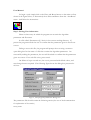
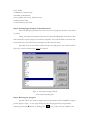
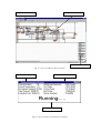
User Manual for the
AutoRoute Program
User Manual
To begin a cycle simply click on the Place and Route button on the main tool bar
shown in the figure below, or alternatively chose Place and Route from the “AutoRoute”
menu. And follow the instructions.
Step 1: Getting User information
There are three ways in which the program can ascertain the algorithm
parameters and file names:
In a file called “Parameters.cfg” that is in the current working directory. If
present the program will ask the user to confirm that the parameters given in the file are
correct.
Failing to access this file, the program will prompt the user using a common
open dialog box for the name of a file that contains the algorithm parameters. On
successfully reading the parameters, the user will be asked to confirm that the parameters
given are correct. If no such file exists, press cancel.
On failure of steps one and two, the user is presented with default values, and
may change them as required. The following figure shows the dialog box presented to
the user.
Fig.C.1, The program parameters dialog box.
The parameters file should contain the following entries (See rest of the documentation
for explanation of the entries)
MAX_TEMP
STEP_TEMP
NUMBER_OF_ITERATIONS
OPTIMISE_PARAMETER
MAX_WORSE_SOLUTION_PERCENTAGE
NETLIST_FILENAME
CONSTRAINTS_FILENAME
Step 2: Getting Input/Output Node Information
The next dialog box presented to the user has two purposes related to the choice
of nodes.
Firstly, the input and output nodes may be selected individually from the list box
and classified as input/output/or internal as required. All nodes default to internal, and
any mistakes may be undone by returning the nodes internal status.
Secondly, if the cost function selected in the first dialog box was “Critical Node”,
then one or more critical nodes must be selected.
Fig.C.2, The input/output/critical
node selection dialog box.
Step 3: Running the program
The GUI does not need or require any user interaction, which simplifies usage as
per the project scope. At any stage during the run, the program may be paused by
selecting Autoroute ! Pause or clicking the
button on the tool bar. While in the
paused mode, it is possible to zoom in or out on a particular region of the design. By
clicking on a device, information with respect to the devices label, channel width and
length are displayed in a message box. The metal layers (and only the metal layers) may
be enabled and disabled by selecting the appropriate layer from the legend.
Step 4: GDSII Stream Binary File
The final stage of placement is GDSII file output. Once the algorithm has
finished, a message box will display some information about the run. The program
always resorts back to the best solution found during the run. Click OK and a common
save dialog box will be presented. Enter the name you want to save the GDSII stream
binary file as, and click save. A message box will indicate if the write was successful or
otherwise.
GUI Explanation
The GUI is divided into two separate windows, a graphical display of the current
solution and an information window. Both windows are illustrated in the following two
diagrams on the next page.
Current Layout
AutoRoute ToolBar
AutoRoute Legend
Fig. C.3, The AutoRoute Main window.
Timing Information
Placement Information
Current Status
Fig.C.4, The AutoRoute Information window.