1
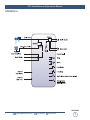
INC
®
Installation and Operation Manual
TT-1 Rev. E PCB
Telephone Line Powered Auto-Answer Hybrid/Coupler
Manual update 01/25/06
Due to the dynamic nature of product design, the information contained in this
document is subject to change without notice. Broadcast Tools, Inc., assumes no
responsibility for errors and/or omissions contained in this document. Revisions
of this information or new editions may be issued to incorporate such changes.
Broadcast Tools® is a registered trademark of Broadcast Tools, Inc.
Copyright, 1989 - 2005 by Broadcast Tools, Inc. All rights reserved.
No part of this document may be reproduced or distributed without permission.
Visit www.broadcasttools.com for important product update information.
TT-1 Installation and Operation Manual
INTRODUCTION
Thank you for your purchase of the tiny TOOLS™ TT-1, Telephone Line
Powered Auto-Answer/Auto-disconnect Hybrid/Coupler, which we will refer to
throughout the manual as the TT-1. We’re confident this product will give you
many years of dependable service. This manual is intended to give you all the
information needed to install and operate the product.
SAFETY INFORMATION
CAUTION!
Broadcast Tools®
Products, as with any
electronic device, can
fail without warning.
Do not use this product
in applications where a
life threatening condition
could result due to failure.
Only qualified personnel should install Broadcast Tools® products. Incorrect or
inappropriate use and/or installation could result in a hazardous condition.
WHO TO CONTACT FOR HELP
If you have any questions regarding your product or you need assistance, please contact your distributor from whom you purchased this equipment.
NOTE:
This manual should be
read thoroughly before
installation and operation.
If you would like more information about Broadcast Tools® products, you may
reach us at:
Broadcast Tools, Inc.
131 State Street
Sedro-Woolley, WA 98284 USA
Voice: 360 . 854 . 9559
Fax: 360 . 854 . 9479
WEBSITE:
Internet Home Page: www.broadcasttools.com
E-mail:
[email protected]
THANK YOU FOR CHOOSING
BROADCAST TOOLS® BRAND PRODUCTS!
Visit our web site for
product updates and
additional information
INTRODUCTION
e-mail: [email protected] voice: 360.854.9559 fax: 360.854.9479
2
TT-1 Installation and Operation Manual
PRODUCT DESCRIPTION
The tiny TOOLS TT-1 is more than just an ordinary telephone line coupler.
The TT-1 is a rack-able compact telephone line powered auto-answer and auto-disconnect hybrid/coupler. The TT-1 utilizes dual-hybrid transformers providing full
duplex audio at a plain old coupler price. We provide a rear panel multi-turn hybrid
NULL trimmer to allow the user to achieve approximately 20db separation figures.
Additional TT-1 features: front panel line seize button, call drop button, autoanswer/monitor-TAP switch, audio mute switch, and off-hook and ring indicators. A
rear panel RJ-11 is provide for connection to a POTS line along with a second RJ11 loop-thru jack that may be configured to disconnect attached devices when the
TT-1 goes off-hook. Plug-in euroblock screw terminals along with 3.5mm jacks are
provided for balanced send and caller audio. Plug-in euroblock screw terminals are
provided for remote seize and drop inputs and the SPDT off-hook dry relay contacts.
The TT-1 may be set on a desktop, mounted on a wall or up to four units mounted
on the RA-1, Rack-Able mounting shelf.
INSTALLATION
Please examine your TT-1 carefully for any damage that may have been sustained
during shipping. If any is noted, please notify the shipper immediately and retain
the
packaging
for
inspection
by
the
shipper.
The package contains the TT-1, modular cable and this manual.
Installation of the TT-1 in high RF environments should be performed with care.
Shielded cable is suggested for all audio connections. All shields should be tied to
the “C-GND” Chassis GrouND terminals. The station ground should be connected
to the chassis ground screw located on the far right side of the TT-1 as viewed from
the rear. It is recommended that all cables connected to the TT-1 be looped through
ferrite cores to suppress RF.
NOTE:
Some features may
require the removing of
the chassis cover.
Caution should be
observed, as hazardous
voltages may be present
on the printed circuit
board. Be sure to reinstall the cover before
using the TT-1.
Telco line jack: Connect your telephone line to this modular RJ-11 jack labeled
“
L
I
N
E
”
.
To have the TT-1 automatically disconnect when a caller hangs up, verify that the
telephone company has enabled the “CPC” calling party disconnect (wink) feature.
TIP: If you have trouble seizing the telephone line, try reversing the
tip and ring.
Loop-thru line jack: Connect your telephone set or other telephone type equipment to the jack labeled “LOOP”. When the internal “BYPASS” jumper JP1 is
removed, the device connected to this jack will be disconnected when the TT-1
answers the line. To bypass this feature, place a jumper over JP1 (factory default).
Send Input: Low Z, transformer balanced. Connect your (send to telephone line)
equipment’s output to the SEND + and SEND - rear panel plug-in euroblock screw terminals or the 3.5 stereo jack labeled ”SEND”. The level should be limited to –9dBu.
DESCRIPTION
e-mail: [email protected] voice: 360.854.9559 fax: 360.854.9479
3
TT-1 Installation and Operation Manual
Caller Output: Low Z, transformer balanced. Connect your (caller audio from
telephone line) equipment’s input to the CALLER + and CALLER - plug-in
euroblock screw terminals or the 3.5 stereo jack labeled “CALLER” rear panel
screws. The caller audio level may vary from –9dBu to –20dBu. Note:
Additional external amplification may be required.
Relay connections: The “OFF-HOOK” relay may be connected to either the K1CM (wiper) and K1-NO (normally open) terminals or the K1-NC (normally closed)
terminal. When the line is answered (seized), the normally open contacts will close
and the front panel “HOOK” LED will light.
Remote Seize: Connect a positive voltage (no greater than 6 vdc) to the Seize + terminal and ground to the Seize – terminal to seize (answer) the (call) line.
Remote Drop: Connect a positive voltage (no greater than 6 vdc) to the Drop + terminal and ground to the Drop – terminal to drop (disconnect) the (call) line.
Ring LED: Front panel LED will light when the coupler is called. The TT-1 will
go off-hook during or after the first ring.
Hook LED: Lights when the TT-1 has seized the telephone line.
Mute Switch: Used to disconnect the SEND & CALLER audio from the hybrid
with the switch IN. This feature may be disabled on the CALLER side by installing
JP2 & JP3 (factory default).
Monitor (TAP) Switch: Used to select between the auto-answer mode and the TAP
m
o
d
e
.
When this switch is IN, the TT-1 will TAP (monitor) a telephone line without seizing the line. When the switch is OUT, the TT-1 will auto-answer any call on the
first ring.
Null adjustment pot: Used to adjust the null between the send and caller audio. To
adjust the TT-1 null, follow the steps:
1 - Connect a telephone line to the RJ-11 line jack.
2 - Connect an audio source to the SEND +/- terminals. Use a 700 hz tone at
–9dBm.
3 - Connect a dB meter to the CALLER +/- terminals. Be sure to terminate with
600 ohms.
4 - Make a call to the TT-1. After the TT-1 answers, adjust the NULL trimmer for
minimum (NULL) level on the (CALLER) dB meter.
WEBSITE:
Visit our web site for
product updates and
additional information
The TT-1 is now ready for normal operation.
INSTALLATION
e-mail: [email protected] voice: 360.854.9559 fax: 360.854.9479
4
TT-1 Installation and Operation Manual
SPECIFICATIONS
Input Level
-9dBu.
Input Impedance
600 ohms, transformer balanced.
Output Level
-9dBu to –20dBu.
Output Impedance
600 ohms, transformer balanced.
Relay
SPDT, 30Vdc / 1 amp.
NOTE:
For safety, never connect 120 Vac circuits
to these relays!
Remote seize/drop input voltage:
5 to 6 Vdc@30ma.
FCC information:
Complies with FCC parts 15 & 68
Ringer equivalence:
0.4B
Connectors:
Telco: 2 x modular RJ-11
Audio:
Plugin euroblock screw terminals and
3.5mm stereo jacks
Remote:
Plugin euroblock screw terminals
Size:
1/4” rack space, 4.20” x 6.00” x 1.55”,
painted chassis w/ 4 - mounting holes.
Weight:
2.0 lb.
Options:
RA-1, Rack Shelf. 1 RU.
SPECIFICATIONS
e-mail: [email protected] voice: 360.854.9559 fax: 360.854.9479
5
TT-1 Installation and Operation Manual
LIMITED WARRANTY
The term “Buyer” as used in this document refers to and includes both (but only) (a) any person or entity who acquires such an item for
the purpose of resale to others (i.e., a dealer or distributor of an item), and (b) the first person or entity who acquires such an item for
such person’s or entity’s own use.
Broadcast Tools warrants to each Buyer of any item manufactured by Broadcast Tools that the item will be free from defects in materials and workmanship at the time it is shipped by Broadcast Tools if the item is properly installed, used and maintained.
EXCLUSIVE REMEDIES
If Broadcast Tools is notified, in writing, of a failure of any item manufactured by Broadcast Tools to conform to the foregoing Limited
Warranty within one (1) year following the date of the Buyer’s acquisition of the item, and if the item is returned to Broadcast Tools in
accordance with Broadcast Tools’ instructions for confirmation by inspection of the defect (which at Broadcast Tools’ election may
include, without limitation, a requirement that the Buyer first obtain a Return Authorization number from Broadcast Tools, that the Buyer
furnish proof of purchase in the form of an invoice and/or receipt, and that the Buyer prepay all freight charges associated with any return
of the item to Broadcast Tools using such freight service as Broadcast Tools reasonably may specify), Broadcast Tools will repair or
replace the defective item, or will refund the purchase price paid by the Buyer for the item. Broadcast Tools shall have the exclusive
right to choose between these alternative remedies.
NO OTHER WARRANTIES OR REMEDIES
TO THE MAXIMUM EXTENT PERMITTED BY APPLICABLE LAW, BROADCAST TOOLS AND ITS SUPPLIERS DISCLAIM ALL OTHER
WARRANTIES, EITHER EXPRESS OR IMPLIED, INCLUDING BUT NOT LIMITED TO IMPLIED WARRANTIES OF MERCHANTABILITY OR FITNESS FOR A PARTICULAR PURPOSE; AND THE FOREGOING ALTERNATIVE REMEDIES SHALL BE EXCLUSIVE OF
ALL OTHER REMEDIES. THIS LIMITED WARRANTY GIVES YOU SPECIFIC LEGAL RIGHTS. YOU MAY HAVE OTHER RIGHTS,
WHICH VARY FROM STATE/JURISDICTION TO STATE/JURISDICTION.
NO LIABILITY FOR CONSEQUENTIAL DAMAGES
TO THE MAXIMUM EXTENT PERMITTED BY APPLICABLE LAW, NEITHER BROADCAST TOOLS NOR ANY OF ITS SUPPLIERS
SHALL HAVE ANY LIABILITY FOR ANY SPECIAL, INCIDENTAL, INDIRECT, CONSEQUENTIAL OR PUNITIVE DAMAGES WHATSOEVER (INCLUDING, WITHOUT LIMITATION, ANY DAMAGES FOR LOST PROFITS, BUSINESS INTERRUPTION, LOSS OF DATA OR
INFORMATION, COST OF CAPITAL, CLAIMS OF CUSTOMERS, OR ANY OTHER PECUNIARY LOSS) ARISING OUT OF THE USE
OF OR THE INABILITY TO USE ANY ITEM SUPPLIED BY BROADCAST TOOLS, EVEN IF BROADCAST TOOLS HAS BEEN
ADVISED OF THE POSSIBILITY OF SUCH DAMAGES HAVE ANY LIABILITY FOR ANY SPECIAL, INCIDENTAL, CONSEQUENTIAL,
EXEMPLARY OR PUNITIVE DAMAGES. THIS LIMITATION OF LIABILITY APPLIES WHETHER A CLAIM IS ONE ALLEGING
BREACH OF A CONTRACT OR WARRANTY, NEGLIGENCE OR OTHER TORT, FOR THE VIOLATION OF ANY STATUTORY DUTY,
THE FAILURE OF ANY LIMITED OR EXCLUSIVE REMEDY TO ACHIEVE ITS ESSENTIAL PURPOSE, OR ANY OTHER CLAIM OF
ANY NATURE. BECAUSE SOME STATES AND JURISDICTIONS DO NOT ALLOW THE EXCLUSION OR LIMITATION OF LIABILITY
FOR INCIDENTAL OR CONSEQUENTIAL DAMAGES, THIS LIMITATION MAY NOT APPLY TO YOU.
Broadcast Tools, Inc.
131 State Street
Sedro-Woolley, WA 98284 • USA
360.854.9559 voice • 360.854.9479 fax
[email protected] e-mail
www.broadcasttools.com website
LIMITED WARRANTY
e-mail: [email protected] voice: 360.854.9559 fax: 360.854.9479
6
TT-1 Installation and Operation Manual
APPENDIX A
APPENDIX
e-mail: [email protected] voice: 360.854.9559 fax: 360.854.9479
7